EP4047326A1 - Sensoranordnung - Google Patents
Sensoranordnung Download PDFInfo
- Publication number
- EP4047326A1 EP4047326A1 EP21213963.8A EP21213963A EP4047326A1 EP 4047326 A1 EP4047326 A1 EP 4047326A1 EP 21213963 A EP21213963 A EP 21213963A EP 4047326 A1 EP4047326 A1 EP 4047326A1
- Authority
- EP
- European Patent Office
- Prior art keywords
- holder
- optical sensor
- sensor
- sensor arrangement
- fastening
- Prior art date
- Legal status (The legal status is an assumption and is not a legal conclusion. Google has not performed a legal analysis and makes no representation as to the accuracy of the status listed.)
- Granted
Links
Images





Classifications
-
- G—PHYSICS
- G01—MEASURING; TESTING
- G01V—GEOPHYSICS; GRAVITATIONAL MEASUREMENTS; DETECTING MASSES OR OBJECTS; TAGS
- G01V8/00—Prospecting or detecting by optical means
- G01V8/10—Detecting, e.g. by using light barriers
- G01V8/12—Detecting, e.g. by using light barriers using one transmitter and one receiver
-
- G—PHYSICS
- G01—MEASURING; TESTING
- G01D—MEASURING NOT SPECIALLY ADAPTED FOR A SPECIFIC VARIABLE; ARRANGEMENTS FOR MEASURING TWO OR MORE VARIABLES NOT COVERED IN A SINGLE OTHER SUBCLASS; TARIFF METERING APPARATUS; MEASURING OR TESTING NOT OTHERWISE PROVIDED FOR
- G01D11/00—Component parts of measuring arrangements not specially adapted for a specific variable
- G01D11/24—Housings ; Casings for instruments
- G01D11/26—Windows; Cover glasses; Sealings therefor
Definitions
- the invention relates to a sensor arrangement according to the preamble of claim 1.
- Such sensor arrangements are used in various industrial applications for monitoring purposes.
- the sensor arrangement has an optical sensor, by means of which object detections can be carried out in a monitored area.
- optical sensors can be designed, for example, in the form of light barriers, light sensors, reflection light screws, distance sensors and the like.
- optical sensors are used in industrial applications to monitor objects, in particular on systems such as machines, conveyor systems, driverless systems and the like. To do this, the optical sensor must be attached to the system with a suitable bracket.
- mounts often have a structurally complex structure and require a relatively large amount of installation space on the system.
- holders can only be installed in a specific installation position on a system surface, which can lead to undesirable restrictions on the sensor arrangement in the respective application.
- the object of the invention is to provide a sensor arrangement with extended functionality.
- the invention relates to a sensor arrangement with an optical sensor and a holder which is designed to accommodate the optical sensor.
- the optical sensor has sensor components arranged in a housing, which emit and/or receive light beams, a front wall of the housing forming a light exit surface through which the light beams are guided.
- the holder has fastening means, by means of which fastening to a base can be carried out in two fastening planes.
- the holder has a transparent cover plate, which lies in front of the light exit surface when the optical sensor is accommodated in the holder.
- the holder has sockets for receiving fastening means, by means of which fastening to a base can be carried out in a first fastening plane.
- a significant advantage of the sensor arrangement according to the invention is that the holder forms two different attachment levels, ie the holder can be attached in different attachment levels to a base, for example on a contact surface of a system on which the optical sensor performs monitoring functions. In this way, different installation positions of the optical sensor can be realized, as a result of which a particularly simple and flexible adaptation to different applications is possible.
- a further advantage of the sensor arrangement according to the invention is that the holder has a cover plate which is a protective cover for forms the light exit surface of the optical sensor mounted in the holder.
- the cover pane Since the cover pane is transparent, it does not obstruct the beam path of the light beams guided through the light exit surface. On the one hand, the cover pane provides mechanical protection for the optical sensor against the effects of shock and impact. Furthermore, the cover plate prevents soiling of the light exit surface, since dust, dirt particles and also moisture are kept away from the cover plate.
- the cover plate has an orientation that is preferably inclined relative to the horizontal, so that dust and dirt particles can be detached from it automatically or more easily by wiping, simply as a result of gravity.
- the cover pane expediently runs in a plane which is oriented at an angle of inclination to the light exit surface of the optical sensor fixed in the holder.
- the cover pane also advantageously extends over the entire area of the light exit surface of the optical sensor.
- the cover pane thus ensures complete, area-wide protection of the light exit surface of the optical sensor.
- the holder has sockets for receiving fastening means, by means of which fastening to a base can be carried out in a first fastening plane.
- Two sockets are provided on opposite sides of the bracket.
- the sockets which are preferably of identical design, are exposed with their openings, so that the fastening means for fixing the holder to fixed bases, in particular parts of the system, can be fixed there.
- the fastening means can be in the form of screws or clips.
- the sockets are advantageously arranged along a pivot axis.
- the orientation of the holder can thus be varied in a simple manner by pivoting movements.
- the holder can be fixed to a base in a further fastening plane.
- fastening holes for accommodating fastening means are provided on a segment of the holder lying in a second fastening plane.
- the segment is expediently designed in the form of a plate.
- the segment formed in this way forms a flat contact surface with which the holder can be fixed to a base.
- the fastening means are formed by screws or clips.
- bayonet locking means are provided in a second fastening level.
- the bayonet locking means forming the fastening means are located on a plate-shaped segment of the holder, which can be fixed to a base.
- the optical sensor can be fixed in the holder by means of tensioning, clamping or latching means.
- the optical sensor is mounted in a predetermined storage position in the holder.
- the optical sensor can thus be fixed in the holder without the use of tools. It is particularly advantageous that the optical sensor is mounted in a defined target position in the holder, as a result of which a reproducible, defined installation position of the optical sensor is obtained.
- This target position is advantageously realized by a contour of the holder that is adapted to the outer contour of the optical sensor.
- the holder has an elastic clamping hook for accommodating the optical sensor.
- the bracket also has holes to secure the sensor with screws under extreme vibration loads.
- the optical sensor can work according to the light barrier principle, so that in a first housing a transmitter emitting light beams and in a second housing, a light beam receiving receiver are integrated.
- each housing of the optical sensor can be stored in a separate holder.
- the optical sensor particularly advantageously has, as sensor components, a transmitter that emits transmitted light beams and a receiver that receives received light beams.
- the optical sensor can then be designed as a light scanner, reflection light barrier, distance sensor and the like.
- the optical sensor can be designed in particular in such a way that the transmitted light beams and received light beams are guided through spatially separate areas of the light exit surface.
- the holder is particularly advantageously adapted to the optical sensor in such a way that an opaque web is provided on the cover plate, which separates the transmitted light beams and received light beams.
- the figures 1 and 2 show an exemplary embodiment of the sensor arrangement 1 according to the invention.
- the sensor arrangement 1 comprises an optical sensor 2 and a holder 3, in which the optical sensor 2 can be stored and which can be fixed to a base.
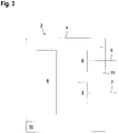
- FIG 3 shows a schematic representation of the optical sensor 2, which is designed as a light sensor in the present case.
- the components of the optical sensor 2 are integrated in an essentially cubic housing 4 .
- the optical sensor 2 has a transmitter 6 emitting transmitted light beams 5 and a receiver 8 receiving received light beams 7 as sensor components.
- the transmitter 6 can be formed by a light-emitting diode, for example, and the receiver 8 by a photodiode.
- the transmitter 6 and receiver 8 can optics, not shown, may be assigned, for example in the form of lenses, which are used for beam shaping of the transmitted light beams 5 and received light beams 7 .
- an evaluation unit 9 which can be in the form of a microprocessor or the like. The evaluation unit 9 is used to control the transmitter 6.
- an object detection signal is generated in the evaluation unit 9 as a function of received signals generated in the receiver 8, the signal states of which indicate whether an object is within a monitoring area monitored by the optical sensor 2 or not.
- the object detection signal is output via an output which is integrated in a connection 10, in particular a plug, via which the optical sensor 2 is also supplied with power.
- the transmitted light beams 5 are guided into the monitored area through an exit window 11 forming a light exit surface. From an object in the monitored area, the transmitted light beams 5 are guided back to the optical sensor 2 as received light beams 7 and pass through the exit window 11 to the receiver 8. How figure 3 shows, the transmitted light beams 5 and received light beams 7 pass through different areas of the light exit surface.
- the holder 3 advantageously consists of a glass fiber reinforced plastic.
- the holder 3 like the figures 1 and 2 show a U-profile segment 3a, which is used to abut a side wall of the housing 4 of the optical sensor 2.
- An elastically deformable clamping hook 12 ends at the U-profile segment 3a ( figure 2 ). This forms a tensioning or clamping connection with which the optical sensor 2 can be stored in a desired position, ie a predetermined storage position in the holder 3, as shown in FIGS figures 1 and 2 shown. It can also be secured with screws.
- connection part 3b of the holder 3 connects to the U-profile segment 3a of the holder 3 .
- On the connector part 3b are two identical ones, coaxial along a pivot axis arranged sockets 13 are provided. Fastening means can be introduced into these bushings 13 in order to fix the holder 3 to a base such as, for example, a piece of equipment.
- the connecting part 3b also includes a plate-shaped segment 14 in which two elongated holes 15 are provided.
- the plate-shaped segment 14 has a flat contact surface for contact with a base to which the holder 3 is to be attached.
- Fastening means such as, for example, fastening screws 15a can be inserted into the elongated holes 15 of the plate-shaped segment 14 for fastening to the base.
- connection part 3b of the holder 3 there is also a transparent cover plate 16 which is permeable to the transmitted light beams 5 and received light beams 7 .
- the flat cover plate 16 is at a distance in front of the light exit surface of the optical sensor 2 mounted in the holder 3.
- the cover plate 16 covers the entire area in front of the light exit surface and protects it against impact and impact. Furthermore, the cover plate 16 protects the light exit surface against contamination such as dust and also against moisture.
- the plane of the cover plate 16 is inclined to the plane of the light exit surface. Furthermore, the cover plate 16 runs inclined to the horizontal when the holder 3 is fixed to a base. Due to the inclined position of the cover plate 16, dirt and dust particles are easily detached from it, in particular due to the force of gravity.
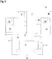
- the figures 4 and 5 show in more detail the holder 3 of the sensor arrangement 1 according to the invention.
- An opaque web 17 is provided on the holder, which optically separates the transmitted light beams 5 and received light beams 7, which are guided over spatially separate areas of the light exit surface of the optical sensor 2.
- the embodiment according to the figures 4 and 5 the embodiment of the figures 1 and 2 .
- the holder 3 is attached to a base in the form of a carrier 18 in the present case. Fastening takes place in that fastening screws 15a forming fastening means are passed through the elongated holes 15 of the plate-shaped segment 14 and are anchored in the carrier 18 .
- clips 19 as in figure 6 shown are used.
- FIG 7 shows a section of a further embodiment of the holder 3 for the sensor arrangement 1.
Landscapes
- Physics & Mathematics (AREA)
- Life Sciences & Earth Sciences (AREA)
- General Life Sciences & Earth Sciences (AREA)
- General Physics & Mathematics (AREA)
- Geophysics (AREA)
- Geophysics And Detection Of Objects (AREA)
Abstract
Description
- Die Erfindung betrifft eine Sensoranordnung gemäß dem Oberbegriff des Anspruchs 1.
- Derartige Sensoranordnungen werden in unterschiedlichen industriellen Applikationen zu Überwachungszwecken eingesetzt.
- Hierzu weist die Sensoranordnung einen optischen Sensor auf, mittels dessen Objektdetektionen in einem Überwachungsbereich durchgeführt werden können. Derartige optische Sensoren können beispielsweise in Form von Lichtschranken, Lichttastern, Reflexionslichtschrauben, Distanzsensoren und dergleichen ausgebildet sein.
- Mit derartigen optischen Sensoren werden in industriellen Applikationen Objektüberwachungen insbesondere an Anlagen wie zum Beispiel Maschinen, Förderanlagen, fahrerlosen Systemen und dergleichen durchgeführt. Hierzu muss der optische Sensor mit einer geeigneten Halterung an der Anlage befestigt werden.
- Nachteilig hierbei ist, dass derartige Halterungen oft einen konstruktiv aufwändigen Aufbau aufweisen und dabei einen relativ großen Einbauraum an der Anlage benötigen. Zudem ist nachteilig, dass derartige Halterungen nur in einer bestimmten Einbaulage an einer Anlagenfläche montiert werden können, was zu unerwünschten Einschränkungen der Sensoranordnung in der jeweiligen Applikation führen kann.
- Der Erfindung liegt die Aufgabe zugrunde eine Sensoranordnung mit erweiterter Funktionalität bereitzustellen.
- Zur Lösung dieser Aufgabe sind die Merkmale des Anspruchs 1 vorgesehen. Vorteilhafte Ausführungsformen und zweckmäßige Weiterbildungen der Erfindung sind in den abhängigen Ansprüchen beschrieben.
- Die Erfindung betrifft eine Sensoranordnung mit einem optischen Sensor und einer Halterung, welche zur Aufnahme des optischen Sensors ausgebildet ist. Der optische Sensor weist in einem Gehäuse angeordnete Sensorkomponenten auf, welche Lichtstrahlen emittieren und/oder empfangen, wobei eine Frontwand des Gehäuses eine Lichtaustrittsfläche ausbildet, durch welche die Lichtstrahlen geführt sind. Die Halterung weist Befestigungsmittel auf, mittels derer eine Befestigung an einer Unterlage in zwei Befestigungsebenen durchführbar ist. Die Halterung weist eine transparente Abdeckscheibe auf, welche bei in der Halterung aufgenommenen optischen Sensor vor der Lichtaustrittsfläche liegt. Die Halterung weist Buchsen zur Aufnahme von Befestigungsmitteln auf, mittels derer eine Befestigung an einer Unterlage in einer ersten Befestigungsebene durchführbar ist.
- Ein wesentlicher Vorteil der erfindungsgemäßen Sensoranordnung besteht darin, dass die Halterung zwei unterschiedliche Befestigungsebenen ausbildet, das heißt die Halterung kann in unterschiedlichen Befestigungsebenen an einer Unterlage, beispielsweise an einer Anlagefläche einer Anlage, an welcher der optische Sensor Überwachungsfunktionen ausführt, befestigt werden. Damit können unterschiedliche Einbaulagen des optischen Sensors realisiert werden, wodurch eine besonders einfache und flexible Anpassung an unterschiedliche Applikationen möglich ist.
- Ein weiterer Vorteil der erfindungsgemäßen Sensoranordnung besteht darin, dass die Halterung eine Abdeckscheibe aufweist, die eine Schutzabdeckung für die Lichtaustrittsfläche des in der Halterung gelagerten optischen Sensors ausbildet.
- Da die Abdeckscheibe transparent ist, behindert sie den Strahlengang der durch die Lichtaustrittsfläche geführten Lichtstrahlen nicht. Die Abdeckscheibe sorgt einerseits für einen mechanischen Schutz des optischen Sensors gegen Stoß- und Schlageinwirkungen. Weiterhin verhindert die Abdeckscheibe ein Verschmutzen der Lichtaustrittsfläche, da von der Abdeckscheibe Staub-, Schmutzpartikel und auch Feuchtigkeit abgehalten wird.
- Die Abdeckscheibe weist eine vorzugsweise gegenüber der Horizontalen geneigte Orientierung auf, so dass bereits infolge der Schwerkraft Staub- und Schmutzpartikel von dieser selbsttätig oder leichter durch Abwischen gelöst werden können.
- Zweckmäßig verläuft hierzu die Abdeckscheibe in einer Ebene, die in einem Neigungswinkel zur Lichtaustrittsfläche des in der Halterung fixierten optischen Sensor orientiert ist.
- Weiter vorteilhaft erstreckt sich die Abdeckscheibe über den gesamten Bereich der Lichtaustrittsfläche des optischen Sensors.
- Damit gewährleistet die Abdeckscheibe einen vollständigen, flächendeckenden Schutz der Lichtaustrittsfläche des optischen Sensors.
- Gemäß einer vorteilhaften Ausführungsform weist die Halterung Buchsen zur Aufnahme von Befestigungsmitteln auf, mittels derer eine Befestigung an einer Unterlage in einer ersten Befestigungsebene durchführbar ist.
- Dabei sind zwei Buchsen an gegenüberliegenden Seiten der Halterung vorgesehen.
- Die Buchsen, die vorzugsweise identisch ausgebildet sind, liegen mit ihren Öffnungen frei, so dass dort die Befestigungsmittel zur Fixierung der Halterung an feststehenden Unterlagen, insbesondere Anlagenteilen, fixiert werden können. Die Befestigungsmittel können in Form von Schrauben oder Klipps ausgebildet sein.
- Vorteilhaft sind die Buchsen entlang einer Schwenkachse angeordnet.
- Damit kann die Orientierung der Halterung durch Schwenkbewegungen auf einfache Weise variiert werden.
- Erfindungsgemäß kann die Halterung in einer weiteren Befestigungsebene an einer Unterlage fixiert werden.
- Hierzu sind an einem in einer zweiten Befestigungsebene liegende Segment der Halterung Befestigungslöcher zur Aufnahme von Befestigungsmitteln vorgesehen.
- Zweckmäßig ist das Segment plattenförmig ausgebildet.
- Das so ausgebildete Segment bildet eine ebene Anlagefläche aus, mit der die Halterung an einer Unterlage fixiert werden kann.
- Auch in diesem Fall sind die Befestigungsmittel von Schrauben oder Klipps gebildet.
- Gemäß einer alternativen Ausgestaltung sind in einer zweiten Befestigungsebene Bajonettverschlussmittel vorgesehen.
- Auch in diesem Fall befinden sich die Befestigungsmittel ausbildenden Bajonettverschlussmittel an einem plattenförmigen Segment der Halterung, das an einer Unterlage fixiert werden kann.
- Der Vorteil dieser Variante besteht darin, dass der Bajonettverschluss zur Fixierung an der Unterlage werkzeuglos realisiert werden kann.
- Gemäß einer vorteilhaften Ausführungsform kann der optische Sensor mittels Spann-, Klemm- oder Rastmitteln in der Halterung fixiert werden.
- Dabei ist der optische Sensor in einer vorgegebenen Lagerposition in der Halterung gelagert.
- Der optische Sensor kann somit ohne Einsatz von Werkzeugen in der Halterung fixiert werden. Besonders vorteilhaft ist, dass der optische Sensor in einer definierten Sollposition in der Halterung gelagert wird, wodurch eine reproduzierbare, definierte Einbauposition des optischen Sensors erhalten wird. Diese Sollposition wird vorteilhaft durch eine an die Außenkontur des optischen Sensors angepasste Kontur der Halterung realisiert.
- Besonders vorteilhaft weist die Halterung einen elastischen Spannhaken zur Aufnahme des optischen Sensors auf.
- Die Halterung besitzt außerdem Bohrungen um den Sensor bei extremen Vibrationsbelastungen mit Schrauben zu sichern.
- Dies stellt eine konstruktiv besonders einfache und leicht handhabbare Möglichkeit der Fixierung des optischen Sensors in der Halterung dar.
- Prinzipiell kann der optische Sensor nach dem Lichtschrankenprinzip arbeiten, sodass in einem ersten Gehäuse ein Lichtstrahlen emittierender Sender und in einem zweiten Gehäuse ein Lichtstrahlen empfangender Empfänger integriert sind.
- Dann kann jedes Gehäuse des optischen Sensors in einer separaten Halterung gelagert werden.
- Besonders vorteilhaft weist der optische Sensor als Sensorkomponenten einen Sendelichtstrahlen emittierenden Sender und einen Empfangslichtstrahlen empfangenden Empfänger auf.
- Der optische Sensor kann dann als Lichttaster, Reflexionslichtschranke, Distanzsensor und dergleichen ausgebildet sein.
- Dabei kann der optische Sensor insbesondere derart ausgestaltet sein, dass die Sendelichtstrahlen und Empfangslichtstrahlen durch räumlich getrennte Bereiche der Lichtaustrittsfläche geführt sind.
- In diesem Fall ist die Halterung besonders vorteilhaft derart an den optischen Sensor angepasst, dass an den Abdeckschreiben ein lichtundurchlässiger Steg vorgesehen ist, der die Sendelichtstrahlen und Empfangslichtstrahlen trennt.
- Mit diesem Steg werden ein Übersprechen zwischen den Sendelichtstrahlen und Empfangslichtstrahlen und dadurch bedingte Fehldetektionen des optischen Sensors weitgehend vermieden, das heißt die Halterung verbessert die Nachweissicherheit und damit die Funktionalität des optischen Sensors.
- Die Erfindung wird im Folgenden anhand der Zeichnungen erläutert. Es zeigen:
- Figur 1:
- Erste perspektivische Darstellung eines Ausführungsbeispiels der erfindungsgemäßen Sensoranordnung.
- Figur 2:
- Zweite perspektivische Darstellung eines Ausführungsbeispiels der erfindungsgemäßen Sensoranordnung.
- Figur 3:
- Schematische Darstellung des optischen Sensors der Sensoranordnung gemäß den
Figuren 1 und2 . - Figur 4:
- Perspektivische Darstellung einer Lichttrennung bei der Ausführungsform der
Figuren 1 und2 . - Figur 5:
- Draufsicht auf die Anordnung gemäß
Figur 4 . - Figur 6:
- Einzeldarstellung eines Befestigungsmittels in Form eines Klipps für die Sensoranordnung gemäß den
Figuren 1 und2 . - Figur 7:
- Teildarstellung einer Halterung für eine weitere Variante der Sensoranordnung.
- Figur 8:
- Einzeldarstellung eines Blechs für die Anordnung gemäß
Figur 7 . - Die
Figuren 1 und2 zeigen ein Ausführungsbeispiel der erfindungsgemäßen Sensoranordnung 1. Die Sensoranordnung 1 umfasst einen optischen Sensor 2 und eine Halterung 3, in der der optische Sensor 2 gelagert werden kann und welche an einer Unterlage fixiert werden kann. -
Figur 3 zeigt eine schematische Darstellung des optischen Sensors 2 der im vorliegenden Fall als Lichttaster ausgebildet ist. Die Komponenten des optischen Sensors 2 sind in einem im wesentlichen kubischen Gehäuse 4 integriert. Der optische Sensor 2 weist als Sensorkomponenten einen Sendelichtstrahlen 5 emittierenden Sender 6 und einen Empfangslichtstrahlen 7 empfangenden Empfänger 8 auf. Der Sender 6 kann zum Beispiel von einer Leuchtdiode gebildet sein, der Empfänger 8 von einer Photodiode. Dem Sender 6 und Empfänger 8 können nicht dargestellte Optiken zum Beispiel in Form von Linsen zugeordnet sein, die zur Strahlformung der Sendelichtstrahlen 5 und Empfangslichtstrahlen 7 dienen. Im Gehäuse 4 befindet sich weiterhin eine Auswerteeinheit 9, die in Form eines Mikroprozessors oder dergleichen gebildet sein kann. Die Auswerteeinheit 9 dient zur Steuerung des Senders 6. Zudem wird in der Auswerteeinheit 9 in Abhängigkeit von im Empfänger 8 generierten Empfangssignalen ein Objektfeststellungssignal generiert, dessen Signalzustände angeben, ob sich ein Objekt innerhalb eines vom optischen Sensor 2 überwachten Überwachungsbereich befindet oder nicht. Das Objektfeststellungssignal wird über einen Ausgang ausgegeben, der in einem Anschluss 10, insbesondere einem Stecker integriert ist, über welchen auch die Stromversorgung des optischen Sensors 2 erfolgt. - Zur Durchführung der Überwachungsfunktion werden die Sendelichtstrahlen 5 durch ein eine Lichtaustrittsfläche ausbildendes Austrittsfenster 11 in den Überwachungsbereich geführt. Von einem Objekt im Überwachungsbereich werden die Sendelichtstrahlen 5 als Empfangslichtstrahlen 7 zurück zum optischen Sensor 2 geführt und gelangen durch das Austrittsfenster 11 zum Empfänger 8. Wie
Figur 3 zeigt, durchsetzen die Sendelichtstrahlen 5 und Empfangslichtstrahlen 7 unterschiedliche Bereiche der Lichtaustrittsfläche. - Die Halterung 3 besteht vorteilhaft aus einem glasfaserverstärktem Kunststoff. Dabei weist die Halterung 3, wie die
Figuren 1 und2 zeigen, ein U-Profil-Segment 3a auf, welches zur Anlage einer Seitenwand des Gehäuses 4 des optischen Sensors 2 dient. Am U-Profil-Segment 3a mündet ein elastisch verformbarer Spannhaken 12 aus (Figur 2 ). Dieser bildet eine Spann- oder Klemmverbindung aus, mit der der optische Sensor 2 in einer Sollposition, das heißt einer vorgegebenen Lagerposition in der Halterung 3 gelagert werden kann, wie in denFiguren 1 und2 dargestellt. Außerdem kann er durch Schrauben gesichert werden. - An das U-Profil-Segment 3a der Halterung 3 schließt ein Anschlussteil 3b der Halterung 3 an. An dem Anschlussteil 3b sind zwei identische, koaxial entlang einer Schwenkachse angeordnete Buchsen 13 vorgesehen. In diese Buchsen 13 können Befestigungsmittel eingeführt werden, um die Halterung 3 an einer Unterlage wie zum Beispiel einem Anlagenteil zu fixieren.
- Das Anschlussteil 3b umfasst weiterhin ein plattenförmiges Segment 14 in welchem zwei Langlöcher 15 vorgesehen sind. Das plattenförmige Segment 14 weist eine ebene Anlagefläche zur Anlage an einer Unterlage, an der die Halterung 3 zu befestigen ist, auf. In die Langlöcher 15 des plattenförmigen Segments 14 können Befestigungsmittel wie zum Beispiel Befestigungsschrauben 15a zur Fixierung an der Unterlage eingeführt werden.
- Mit den Buchsen 13 einerseits und dem plattenförmigen Segment 14 mit den Langlöchern 15 andererseits wird eine Befestigung der Halterung 3 an einer Unterlage in zwei Befestigungsebenen ermöglicht.
- Am Anschlussteil 3b der Halterung 3 ist weiterhin eine transparente Abdeckscheibe 16, die durchlässig für die Sendelichtstrahlen 5 und Empfangslichtstrahlen 7 ist, vorgesehen. Die ebene Abdeckscheibe 16 liegt in Abstand vor der Lichtaustrittsfläche des in der Halterung 3 gelagerten optischen Sensors 2.
- Die Abdeckscheibe 16 deckt dabei das komplette Vorfeld vor der Lichtaustrittsfläche ab und schützt diese gegen Schlag- und Stoßeinwirkungen. Weiterhin schützt die Abdeckscheibe 16 die Lichtaustrittsfläche gegen Verschmutzungen wie Staub und auch gegen Feuchtigkeit.
- Wie die
Figuren 1 und2 zeigen, verläuft die Ebene der Abdeckscheibe 16 geneigt zur Ebene der Lichtaustrittsfläche. Weiterhin verläuft die Abdeckscheibe 16 geneigt zur Horizontalen, wenn die Halterung 3 an einer Unterlage fixiert ist. Durch die geneigte Lage der Abdeckscheibe 16 lösen sich von dieser Schmutz-und Staubpartikel, insbesondere auch bedingt durch die Schwerkraft, leicht ab. - Die
Figuren 4 und5 zeigen detaillierter die Halterung 3 der erfindungsgemäßen Sensoranordnung 1. Am Halter ist ein lichtundurchlässiger Steg 17 vorgesehen, der die Sendelichtstrahlen 5 und Empfangslichtstrahlen 7, die über räumlich getrennte Bereiche der Lichtaustrittsfläche des optischen Sensors 2 geführt sind, optisch trennt. Ansonsten entspricht die Ausführungsform gemäß denFiguren 4 und5 der Ausführungsform derFiguren 1 und2 . - Wie aus den
Figuren 4 und5 ersichtlich, ist im vorliegenden Fall die Halterung 3 an einer Unterlage in Form eines Trägers 18 befestigt. Die Befestigung erfolgt dadurch, dass Befestigungsmittel bildende Befestigungsschrauben 15a durch die Langlöcher 15 des plattenförmigen Segments 14 geführt sind und im Träger 18 verankert sind. - Anstelle von Befestigungsmitteln in Form von Schrauben können generell auch Klipps 19 wie in
Figur 6 dargestellt verwendet werden. -
Figur 7 zeigt einen Ausschnitt einer weiteren Ausführungsform der Halterung 3 für die Sensoranordnung 1. In diesem Fall befinden sich Bajonettverschlussmittel 20 an dem plattenförmigen Segment 14. Diese Bajonettverschlussmittel 20 können in Löcher 21 einer Blechplatte 22 (Figur 8 ) als Bestandteil der Unterlage eingedreht werden. -
- (1)
- Sensoranordnung
- (2)
- Optischer Sensor
- (3)
- Halterung
- (3a)
- U-Profil-Segment
- (3b)
- Anschlussteil
- (4)
- Gehäuse
- (5)
- Sendelichtstrahlen
- (6)
- Sender
- (7)
- Empfangslichtstrahlen
- (8)
- Empfänger
- (9)
- Auswerteeinheit
- (10)
- Anschluss
- (11)
- Austrittsfenster
- (12)
- Spannhaken
- (13)
- Buchse
- (14)
- Segment
- (15)
- Langloch
- (15a)
- Befestigungsschraube
- (16)
- Abdeckscheibe
- (17)
- Steg
- (18)
- Träger
- (19)
- Klipp
- (20)
- Bajonettverschlussmittel
- (21)
- Loch
- (22)
- Blechplatte
Claims (15)
- Sensoranordnung (1) mit einem optischen Sensor (2) und einer Halterung (3), welche zur Aufnahme des optischen Sensors (2) ausgebildet ist, wobei der optische Sensor (2) in einem Gehäuse (4) angeordnete Sensorkomponenten aufweist, welche Lichtstrahlen emittieren und/oder empfangen, wobei eine Frontwand des Gehäuses (4) eine Lichtaustrittsfläche ausbildet, durch welche die Lichtstrahlen geführt sind, dadurch gekennzeichnet, dass die Halterung (3) Befestigungsmittel aufweist, mittels derer eine Befestigung an einer Unterlage in zwei Befestigungsebenen durchführbar ist, dass die Halterung (3) eine transparente Abdeckscheibe (16) aufweist, welche bei dem in der Halterung (3) aufgenommenen optischen Sensor (2) vor der Lichtaustrittsfläche liegt, und dass die Halterung (3) Buchsen (13) zur Aufnahme von Befestigungsmitteln aufweist, mittels derer eine Befestigung an einer Unterlage in einer ersten Befestigungsebene durchführbar ist.
- Sensoranordnung (1) nach Anspruch 1, dadurch gekennzeichnet, dass zwei Buchsen (13) an gegenüberliegenden Seiten der Halterung (3) vorgesehen sind, wobei die Buchsen (13) entlang einer Schwenkachse angeordnet sind.
- Sensoranordnung (1) nach einem der Ansprüche 1 oder 2, dadurch gekennzeichnet, dass ein an einem in einer zweiten Befestigungsebene liegenden Segment (13) der Halterung (3) Befestigungslöcher zur Aufnahme von Befestigungsmitteln vorgesehen sind.
- Sensoranordnung (1) nach Anspruch 3, dadurch gekennzeichnet, dass das Segment (13) plattenförmig ausgebildet ist.
- Sensoranordnung (1) nach einem der Ansprüche 1 - 4, dadurch gekennzeichnet, dass die Befestigungsmittel von Schrauben oder Klipps (19) gebildet sind.
- Sensoranordnung (1) nach einem der Ansprüche 1 - 5, dadurch gekennzeichnet, dass in einer zweiten Befestigungsebene Bajonettverschlussmittel (20) vorgesehen sind.
- Sensoranordnung (1) nach einem der Ansprüche 1 - 6, dadurch gekennzeichnet, dass der optische Sensor (2) mittels Spann-, Klemm-oder Rastmitteln in der Halterung (3) fixierbar ist.
- Sensoranordnung (1) nach Anspruch 7, dadurch gekennzeichnet, dass der optische Sensor (2) in einer vorgegebenen Lagerposition in der Halterung (3) gelagert ist.
- Sensoranordnung (1) nach einem der Ansprüche 7 oder 8, dadurch gekennzeichnet, dass die Halterung (3) einen elastischen Spannhaken (12) zur Aufnahme des optischen Sensors (2) aufweist.
- Sensoranordnung nach Anspruch 9, dadurch gekennzeichnet, dass der optische Sensor (2) zusätzlich durch Schrauben gesichert werden kann.
- Sensoranordnung (1) nach einem der Ansprüche 1 - 10, dadurch gekennzeichnet, dass die Abdeckscheibe (16) in einer Ebene verläuft, die in einem Neigungswinkel zur Lichtaustrittsfläche des in der Halterung (3) fixierten optischen Sensors (2) orientiert ist.
- Sensoranordnung (1) nach Anspruch 11, dadurch gekennzeichnet, dass sich die Abdeckscheibe (16) über den gesamten Bereich der Lichtaustrittsfläche des optischen Sensors (2) erstreckt.
- Sensoranordnung (1) nach einem der Ansprüche 1 - 12, dadurch gekennzeichnet, dass der optische Sensor (2) als Sensorkomponente einen Sendelichtstrahlen (5) emittierenden Sender (6) und einen Empfangslichtstrahlen (7) empfangenden Empfänger (8) aufweist.
- Sensoranordnung (1) nach Anspruch 13, dadurch gekennzeichnet, dass die Sendelichtstrahlen (5) und Empfangslichtstrahlen (7) durch räumlich getrennte Bereiche der Lichtaustrittsfläche geführt sind.
- Sensoranordnung (1) nach Anspruch 14, dadurch gekennzeichnet, dass an den Abdeckscheiben (16) ein lichtundurchlässiger Steg (17) vorgesehen ist, der die Sendelichtstrahlen (5) und Empfangslichtstrahlen (7) trennt.
Applications Claiming Priority (1)
| Application Number | Priority Date | Filing Date | Title |
|---|---|---|---|
| DE202021100883.0U DE202021100883U1 (de) | 2021-02-23 | 2021-02-23 | Sensoranordnung |
Publications (2)
| Publication Number | Publication Date |
|---|---|
| EP4047326A1 true EP4047326A1 (de) | 2022-08-24 |
| EP4047326B1 EP4047326B1 (de) | 2023-11-01 |
Family
ID=82020432
Family Applications (1)
| Application Number | Title | Priority Date | Filing Date |
|---|---|---|---|
| EP21213963.8A Active EP4047326B1 (de) | 2021-02-23 | 2021-12-13 | Sensoranordnung |
Country Status (2)
| Country | Link |
|---|---|
| EP (1) | EP4047326B1 (de) |
| DE (1) | DE202021100883U1 (de) |
Citations (4)
| Publication number | Priority date | Publication date | Assignee | Title |
|---|---|---|---|---|
| US6982410B2 (en) * | 2002-08-07 | 2006-01-03 | Omron Corporation | Photoelectric sensor with deflection angle adjustment arrangement |
| DE202010013843U1 (de) * | 2010-09-27 | 2011-02-10 | Balluff Gmbh | Optische Sensorvorrichtung |
| US20140064825A1 (en) * | 2012-09-05 | 2014-03-06 | Sick Ag | Fastening apparatus and method of fastening |
| EP3168643B1 (de) * | 2015-11-16 | 2020-09-30 | Valeo Schalter und Sensoren GmbH | Vorrichtung zur befestigung eines optischen sensors an einem kraftfahrzeug mit justageeinrichtung, sensoranordnung sowie kraftfahrzeug |
Family Cites Families (9)
| Publication number | Priority date | Publication date | Assignee | Title |
|---|---|---|---|---|
| DE20317420U1 (de) | 2003-11-12 | 2004-03-18 | Leuze Electronic Gmbh + Co Kg | Vorrichtung zur Befestigung eines Sensors |
| DE202005011847U1 (de) | 2005-07-28 | 2005-10-27 | Leuze Electronic Gmbh & Co Kg | Optischer Sensor |
| DE202005016936U1 (de) | 2005-10-28 | 2006-02-02 | Sick Ag | Optoelektronische Sensoreinrichtung |
| DE202006003313U1 (de) | 2005-11-30 | 2007-04-05 | Hörmann KG Antriebstechnik | Lichtschrankengehäuse, Lichtschrankenelement und Torvorrichtungen |
| DE202012104793U1 (de) | 2012-12-10 | 2014-03-12 | Sick Ag | Halter |
| DE102013104974B4 (de) | 2013-05-15 | 2022-05-12 | Leuze Electronic Gmbh & Co. Kg | Anordnung mit einer Befestigungseinheit und einem Sensor |
| DE202014105638U1 (de) | 2014-11-24 | 2016-02-25 | Sick Ag | Befestigungsvorrichtung zum Befestigen eines Sensors in dessen Betriebsposition |
| DE202015104063U1 (de) | 2015-08-04 | 2015-09-01 | Leuze Electronic Gmbh & Co. Kg | Optischer Sensor |
| DE202017100231U1 (de) | 2017-01-18 | 2017-01-30 | Leuze Electronic Gmbh + Co Kg | Befestigungsvorrichtung |
-
2021
- 2021-02-23 DE DE202021100883.0U patent/DE202021100883U1/de active Active
- 2021-12-13 EP EP21213963.8A patent/EP4047326B1/de active Active
Patent Citations (4)
| Publication number | Priority date | Publication date | Assignee | Title |
|---|---|---|---|---|
| US6982410B2 (en) * | 2002-08-07 | 2006-01-03 | Omron Corporation | Photoelectric sensor with deflection angle adjustment arrangement |
| DE202010013843U1 (de) * | 2010-09-27 | 2011-02-10 | Balluff Gmbh | Optische Sensorvorrichtung |
| US20140064825A1 (en) * | 2012-09-05 | 2014-03-06 | Sick Ag | Fastening apparatus and method of fastening |
| EP3168643B1 (de) * | 2015-11-16 | 2020-09-30 | Valeo Schalter und Sensoren GmbH | Vorrichtung zur befestigung eines optischen sensors an einem kraftfahrzeug mit justageeinrichtung, sensoranordnung sowie kraftfahrzeug |
Also Published As
| Publication number | Publication date |
|---|---|
| DE202021100883U1 (de) | 2022-05-27 |
| EP4047326B1 (de) | 2023-11-01 |
Similar Documents
| Publication | Publication Date | Title |
|---|---|---|
| EP2050281B1 (de) | Optische messeinrichtung mit zwei kameraeinheiten | |
| DE112017005837B4 (de) | Montagestruktur für ein elektronisches fahrzeugbordgerät | |
| EP2910970B1 (de) | Laserscanner | |
| EP1202886B1 (de) | Sensoreinrichtung zur erfassung einer benetzung auf einer scheibe | |
| DE10244638A1 (de) | Optoelektronische Erfassungseinrichtung | |
| DE102009060392A1 (de) | Sensoreinrichtung für ein Kraftfahrzeug | |
| DE202004003810U1 (de) | Schutzeinrichtung, insbesondere Lichtgitter | |
| DE4312947C1 (de) | Lichtvorhang für Lastenaufzüge | |
| DE102006035842B9 (de) | Fahrzeugleuchte mit einer einstückigen Lichtleiter-Blenden-Einheit | |
| EP4047326B1 (de) | Sensoranordnung | |
| DE10237606A1 (de) | Kameraanordnung für Kraftfahrzeuge | |
| DE102017125686A1 (de) | Optischer Scanner | |
| DE202007011016U1 (de) | Optischer Sensor | |
| DE102007051681A1 (de) | Optoelektronischer Sensor | |
| DE29620422U1 (de) | Optoelektronischer Sensor mit in einem Gehäusegrundkörper integrierten Haltevorrichtungen | |
| EP0576909A1 (de) | Webmaschine mit einem Schussfadenwächter | |
| EP0838370B1 (de) | Fahrzeugleuchte oder -scheinwerfer | |
| DE19844238C2 (de) | Optoelektronische Vorrichtung | |
| DE202005014363U1 (de) | LED-Kennzeichenleuchte mit homogener Lichtverteilung | |
| DE202017100230U1 (de) | Befestigungsvorrichtung | |
| DE19757821C2 (de) | Optoelektronische Sensoreinrichtung | |
| DE202005016936U1 (de) | Optoelektronische Sensoreinrichtung | |
| DE10051517B4 (de) | Sensorgehäuse | |
| EP1574880A1 (de) | Sendeelement für Lichtschranken, Lichtgitter und dergleichen | |
| DE10223624B4 (de) | Gehäuse für optoelektronische Sensoren |
Legal Events
| Date | Code | Title | Description |
|---|---|---|---|
| PUAI | Public reference made under article 153(3) epc to a published international application that has entered the european phase |
Free format text: ORIGINAL CODE: 0009012 |
|
| STAA | Information on the status of an ep patent application or granted ep patent |
Free format text: STATUS: REQUEST FOR EXAMINATION WAS MADE |
|
| 17P | Request for examination filed |
Effective date: 20220627 |
|
| AK | Designated contracting states |
Kind code of ref document: A1 Designated state(s): AL AT BE BG CH CY CZ DE DK EE ES FI FR GB GR HR HU IE IS IT LI LT LU LV MC MK MT NL NO PL PT RO RS SE SI SK SM TR |
|
| REG | Reference to a national code |
Ref country code: DE Ref legal event code: R079 Free format text: PREVIOUS MAIN CLASS: G01D0011300000 Ipc: G01V0008120000 Ref document number: 502021001858 Country of ref document: DE |
|
| RIC1 | Information provided on ipc code assigned before grant |
Ipc: G01D 11/26 20060101ALN20230703BHEP Ipc: G01V 8/12 20060101AFI20230703BHEP |
|
| RIC1 | Information provided on ipc code assigned before grant |
Ipc: G01D 11/26 20060101ALN20230707BHEP Ipc: G01V 8/12 20060101AFI20230707BHEP |
|
| GRAP | Despatch of communication of intention to grant a patent |
Free format text: ORIGINAL CODE: EPIDOSNIGR1 |
|
| STAA | Information on the status of an ep patent application or granted ep patent |
Free format text: STATUS: GRANT OF PATENT IS INTENDED |
|
| GRAS | Grant fee paid |
Free format text: ORIGINAL CODE: EPIDOSNIGR3 |
|
| RIC1 | Information provided on ipc code assigned before grant |
Ipc: G01D 11/26 20060101ALN20230818BHEP Ipc: G01V 8/12 20060101AFI20230818BHEP |
|
| GRAA | (expected) grant |
Free format text: ORIGINAL CODE: 0009210 |
|
| STAA | Information on the status of an ep patent application or granted ep patent |
Free format text: STATUS: THE PATENT HAS BEEN GRANTED |
|
| INTG | Intention to grant announced |
Effective date: 20230908 |
|
| AK | Designated contracting states |
Kind code of ref document: B1 Designated state(s): AL AT BE BG CH CY CZ DE DK EE ES FI FR GB GR HR HU IE IS IT LI LT LU LV MC MK MT NL NO PL PT RO RS SE SI SK SM TR |
|
| REG | Reference to a national code |
Ref country code: GB Ref legal event code: FG4D Free format text: NOT ENGLISH |
|
| REG | Reference to a national code |
Ref country code: CH Ref legal event code: EP |
|
| REG | Reference to a national code |
Ref country code: IE Ref legal event code: FG4D Free format text: LANGUAGE OF EP DOCUMENT: GERMAN |
|
| REG | Reference to a national code |
Ref country code: DE Ref legal event code: R096 Ref document number: 502021001858 Country of ref document: DE |
|
| REG | Reference to a national code |
Ref country code: LT Ref legal event code: MG9D |
|
| REG | Reference to a national code |
Ref country code: NL Ref legal event code: MP Effective date: 20231101 |
|
| PG25 | Lapsed in a contracting state [announced via postgrant information from national office to epo] |
Ref country code: GR Free format text: LAPSE BECAUSE OF FAILURE TO SUBMIT A TRANSLATION OF THE DESCRIPTION OR TO PAY THE FEE WITHIN THE PRESCRIBED TIME-LIMIT Effective date: 20240202 |
|
| PG25 | Lapsed in a contracting state [announced via postgrant information from national office to epo] |
Ref country code: IS Free format text: LAPSE BECAUSE OF FAILURE TO SUBMIT A TRANSLATION OF THE DESCRIPTION OR TO PAY THE FEE WITHIN THE PRESCRIBED TIME-LIMIT Effective date: 20240301 |
|
| PG25 | Lapsed in a contracting state [announced via postgrant information from national office to epo] |
Ref country code: LT Free format text: LAPSE BECAUSE OF FAILURE TO SUBMIT A TRANSLATION OF THE DESCRIPTION OR TO PAY THE FEE WITHIN THE PRESCRIBED TIME-LIMIT Effective date: 20231101 |
|
| PG25 | Lapsed in a contracting state [announced via postgrant information from national office to epo] |
Ref country code: NL Free format text: LAPSE BECAUSE OF FAILURE TO SUBMIT A TRANSLATION OF THE DESCRIPTION OR TO PAY THE FEE WITHIN THE PRESCRIBED TIME-LIMIT Effective date: 20231101 |
|
| PG25 | Lapsed in a contracting state [announced via postgrant information from national office to epo] |
Ref country code: ES Free format text: LAPSE BECAUSE OF FAILURE TO SUBMIT A TRANSLATION OF THE DESCRIPTION OR TO PAY THE FEE WITHIN THE PRESCRIBED TIME-LIMIT Effective date: 20231101 |
|
| PG25 | Lapsed in a contracting state [announced via postgrant information from national office to epo] |
Ref country code: NL Free format text: LAPSE BECAUSE OF FAILURE TO SUBMIT A TRANSLATION OF THE DESCRIPTION OR TO PAY THE FEE WITHIN THE PRESCRIBED TIME-LIMIT Effective date: 20231101 Ref country code: LT Free format text: LAPSE BECAUSE OF FAILURE TO SUBMIT A TRANSLATION OF THE DESCRIPTION OR TO PAY THE FEE WITHIN THE PRESCRIBED TIME-LIMIT Effective date: 20231101 Ref country code: IS Free format text: LAPSE BECAUSE OF FAILURE TO SUBMIT A TRANSLATION OF THE DESCRIPTION OR TO PAY THE FEE WITHIN THE PRESCRIBED TIME-LIMIT Effective date: 20240301 Ref country code: GR Free format text: LAPSE BECAUSE OF FAILURE TO SUBMIT A TRANSLATION OF THE DESCRIPTION OR TO PAY THE FEE WITHIN THE PRESCRIBED TIME-LIMIT Effective date: 20240202 Ref country code: ES Free format text: LAPSE BECAUSE OF FAILURE TO SUBMIT A TRANSLATION OF THE DESCRIPTION OR TO PAY THE FEE WITHIN THE PRESCRIBED TIME-LIMIT Effective date: 20231101 Ref country code: BG Free format text: LAPSE BECAUSE OF FAILURE TO SUBMIT A TRANSLATION OF THE DESCRIPTION OR TO PAY THE FEE WITHIN THE PRESCRIBED TIME-LIMIT Effective date: 20240201 Ref country code: PT Free format text: LAPSE BECAUSE OF FAILURE TO SUBMIT A TRANSLATION OF THE DESCRIPTION OR TO PAY THE FEE WITHIN THE PRESCRIBED TIME-LIMIT Effective date: 20240301 |
|
| PG25 | Lapsed in a contracting state [announced via postgrant information from national office to epo] |
Ref country code: SE Free format text: LAPSE BECAUSE OF FAILURE TO SUBMIT A TRANSLATION OF THE DESCRIPTION OR TO PAY THE FEE WITHIN THE PRESCRIBED TIME-LIMIT Effective date: 20231101 Ref country code: RS Free format text: LAPSE BECAUSE OF FAILURE TO SUBMIT A TRANSLATION OF THE DESCRIPTION OR TO PAY THE FEE WITHIN THE PRESCRIBED TIME-LIMIT Effective date: 20231101 Ref country code: PL Free format text: LAPSE BECAUSE OF FAILURE TO SUBMIT A TRANSLATION OF THE DESCRIPTION OR TO PAY THE FEE WITHIN THE PRESCRIBED TIME-LIMIT Effective date: 20231101 Ref country code: NO Free format text: LAPSE BECAUSE OF FAILURE TO SUBMIT A TRANSLATION OF THE DESCRIPTION OR TO PAY THE FEE WITHIN THE PRESCRIBED TIME-LIMIT Effective date: 20240201 Ref country code: LV Free format text: LAPSE BECAUSE OF FAILURE TO SUBMIT A TRANSLATION OF THE DESCRIPTION OR TO PAY THE FEE WITHIN THE PRESCRIBED TIME-LIMIT Effective date: 20231101 Ref country code: HR Free format text: LAPSE BECAUSE OF FAILURE TO SUBMIT A TRANSLATION OF THE DESCRIPTION OR TO PAY THE FEE WITHIN THE PRESCRIBED TIME-LIMIT Effective date: 20231101 |
|
| PG25 | Lapsed in a contracting state [announced via postgrant information from national office to epo] |
Ref country code: DK Free format text: LAPSE BECAUSE OF FAILURE TO SUBMIT A TRANSLATION OF THE DESCRIPTION OR TO PAY THE FEE WITHIN THE PRESCRIBED TIME-LIMIT Effective date: 20231101 |
|
| PG25 | Lapsed in a contracting state [announced via postgrant information from national office to epo] |
Ref country code: CZ Free format text: LAPSE BECAUSE OF FAILURE TO SUBMIT A TRANSLATION OF THE DESCRIPTION OR TO PAY THE FEE WITHIN THE PRESCRIBED TIME-LIMIT Effective date: 20231101 |
|
| PG25 | Lapsed in a contracting state [announced via postgrant information from national office to epo] |
Ref country code: SK Free format text: LAPSE BECAUSE OF FAILURE TO SUBMIT A TRANSLATION OF THE DESCRIPTION OR TO PAY THE FEE WITHIN THE PRESCRIBED TIME-LIMIT Effective date: 20231101 |
|
| PG25 | Lapsed in a contracting state [announced via postgrant information from national office to epo] |
Ref country code: SM Free format text: LAPSE BECAUSE OF FAILURE TO SUBMIT A TRANSLATION OF THE DESCRIPTION OR TO PAY THE FEE WITHIN THE PRESCRIBED TIME-LIMIT Effective date: 20231101 Ref country code: SK Free format text: LAPSE BECAUSE OF FAILURE TO SUBMIT A TRANSLATION OF THE DESCRIPTION OR TO PAY THE FEE WITHIN THE PRESCRIBED TIME-LIMIT Effective date: 20231101 Ref country code: IT Free format text: LAPSE BECAUSE OF FAILURE TO SUBMIT A TRANSLATION OF THE DESCRIPTION OR TO PAY THE FEE WITHIN THE PRESCRIBED TIME-LIMIT Effective date: 20231101 Ref country code: EE Free format text: LAPSE BECAUSE OF FAILURE TO SUBMIT A TRANSLATION OF THE DESCRIPTION OR TO PAY THE FEE WITHIN THE PRESCRIBED TIME-LIMIT Effective date: 20231101 Ref country code: DK Free format text: LAPSE BECAUSE OF FAILURE TO SUBMIT A TRANSLATION OF THE DESCRIPTION OR TO PAY THE FEE WITHIN THE PRESCRIBED TIME-LIMIT Effective date: 20231101 Ref country code: CZ Free format text: LAPSE BECAUSE OF FAILURE TO SUBMIT A TRANSLATION OF THE DESCRIPTION OR TO PAY THE FEE WITHIN THE PRESCRIBED TIME-LIMIT Effective date: 20231101 |
|
| REG | Reference to a national code |
Ref country code: DE Ref legal event code: R097 Ref document number: 502021001858 Country of ref document: DE |
|
| PG25 | Lapsed in a contracting state [announced via postgrant information from national office to epo] |
Ref country code: LU Free format text: LAPSE BECAUSE OF NON-PAYMENT OF DUE FEES Effective date: 20231213 |
|
| PG25 | Lapsed in a contracting state [announced via postgrant information from national office to epo] |
Ref country code: MC Free format text: LAPSE BECAUSE OF FAILURE TO SUBMIT A TRANSLATION OF THE DESCRIPTION OR TO PAY THE FEE WITHIN THE PRESCRIBED TIME-LIMIT Effective date: 20231101 |
|
| REG | Reference to a national code |
Ref country code: BE Ref legal event code: MM Effective date: 20231231 |
|
| PG25 | Lapsed in a contracting state [announced via postgrant information from national office to epo] |
Ref country code: MC Free format text: LAPSE BECAUSE OF FAILURE TO SUBMIT A TRANSLATION OF THE DESCRIPTION OR TO PAY THE FEE WITHIN THE PRESCRIBED TIME-LIMIT Effective date: 20231101 Ref country code: LU Free format text: LAPSE BECAUSE OF NON-PAYMENT OF DUE FEES Effective date: 20231213 |
|
| PLBE | No opposition filed within time limit |
Free format text: ORIGINAL CODE: 0009261 |
|
| STAA | Information on the status of an ep patent application or granted ep patent |
Free format text: STATUS: NO OPPOSITION FILED WITHIN TIME LIMIT |
|
| 26N | No opposition filed |
Effective date: 20240802 |
|
| REG | Reference to a national code |
Ref country code: IE Ref legal event code: MM4A |
|
| PG25 | Lapsed in a contracting state [announced via postgrant information from national office to epo] |
Ref country code: IE Free format text: LAPSE BECAUSE OF NON-PAYMENT OF DUE FEES Effective date: 20231213 |
|
| PG25 | Lapsed in a contracting state [announced via postgrant information from national office to epo] |
Ref country code: BE Free format text: LAPSE BECAUSE OF NON-PAYMENT OF DUE FEES Effective date: 20231231 |
|
| P01 | Opt-out of the competence of the unified patent court (upc) registered |
Free format text: CASE NUMBER: APP_50849/2024 Effective date: 20240909 |
|
| PG25 | Lapsed in a contracting state [announced via postgrant information from national office to epo] |
Ref country code: FR Free format text: LAPSE BECAUSE OF NON-PAYMENT OF DUE FEES Effective date: 20240101 |
|
| PG25 | Lapsed in a contracting state [announced via postgrant information from national office to epo] |
Ref country code: SI Free format text: LAPSE BECAUSE OF FAILURE TO SUBMIT A TRANSLATION OF THE DESCRIPTION OR TO PAY THE FEE WITHIN THE PRESCRIBED TIME-LIMIT Effective date: 20231101 |
|
| PG25 | Lapsed in a contracting state [announced via postgrant information from national office to epo] |
Ref country code: SI Free format text: LAPSE BECAUSE OF FAILURE TO SUBMIT A TRANSLATION OF THE DESCRIPTION OR TO PAY THE FEE WITHIN THE PRESCRIBED TIME-LIMIT Effective date: 20231101 Ref country code: IE Free format text: LAPSE BECAUSE OF NON-PAYMENT OF DUE FEES Effective date: 20231213 Ref country code: FR Free format text: LAPSE BECAUSE OF NON-PAYMENT OF DUE FEES Effective date: 20240101 Ref country code: BE Free format text: LAPSE BECAUSE OF NON-PAYMENT OF DUE FEES Effective date: 20231231 |
|
| PG25 | Lapsed in a contracting state [announced via postgrant information from national office to epo] |
Ref country code: RO Free format text: LAPSE BECAUSE OF FAILURE TO SUBMIT A TRANSLATION OF THE DESCRIPTION OR TO PAY THE FEE WITHIN THE PRESCRIBED TIME-LIMIT Effective date: 20231101 |
|
| PG25 | Lapsed in a contracting state [announced via postgrant information from national office to epo] |
Ref country code: FI Free format text: LAPSE BECAUSE OF FAILURE TO SUBMIT A TRANSLATION OF THE DESCRIPTION OR TO PAY THE FEE WITHIN THE PRESCRIBED TIME-LIMIT Effective date: 20231101 |
|
| PG25 | Lapsed in a contracting state [announced via postgrant information from national office to epo] |
Ref country code: CY Free format text: LAPSE BECAUSE OF FAILURE TO SUBMIT A TRANSLATION OF THE DESCRIPTION OR TO PAY THE FEE WITHIN THE PRESCRIBED TIME-LIMIT; INVALID AB INITIO Effective date: 20211213 |
|
| REG | Reference to a national code |
Ref country code: CH Ref legal event code: PL |
|
| PG25 | Lapsed in a contracting state [announced via postgrant information from national office to epo] |
Ref country code: CH Free format text: LAPSE BECAUSE OF NON-PAYMENT OF DUE FEES Effective date: 20241231 |
|
| PG25 | Lapsed in a contracting state [announced via postgrant information from national office to epo] |
Ref country code: TR Free format text: LAPSE BECAUSE OF FAILURE TO SUBMIT A TRANSLATION OF THE DESCRIPTION OR TO PAY THE FEE WITHIN THE PRESCRIBED TIME-LIMIT Effective date: 20231101 |
|
| PGFP | Annual fee paid to national office [announced via postgrant information from national office to epo] |
Ref country code: DE Payment date: 20251211 Year of fee payment: 5 |
|
| PGFP | Annual fee paid to national office [announced via postgrant information from national office to epo] |
Ref country code: AT Payment date: 20260113 Year of fee payment: 5 |
|
| PG25 | Lapsed in a contracting state [announced via postgrant information from national office to epo] |
Ref country code: HU Free format text: LAPSE BECAUSE OF FAILURE TO SUBMIT A TRANSLATION OF THE DESCRIPTION OR TO PAY THE FEE WITHIN THE PRESCRIBED TIME-LIMIT; INVALID AB INITIO Effective date: 20211213 |