EP4047288A1 - Heat medium circulation system - Google Patents
Heat medium circulation system Download PDFInfo
- Publication number
- EP4047288A1 EP4047288A1 EP21207696.2A EP21207696A EP4047288A1 EP 4047288 A1 EP4047288 A1 EP 4047288A1 EP 21207696 A EP21207696 A EP 21207696A EP 4047288 A1 EP4047288 A1 EP 4047288A1
- Authority
- EP
- European Patent Office
- Prior art keywords
- heat medium
- gas
- separating portion
- liquid separating
- refrigerant
- Prior art date
- Legal status (The legal status is an assumption and is not a legal conclusion. Google has not performed a legal analysis and makes no representation as to the accuracy of the status listed.)
- Granted
Links
Images


Classifications
-
- F—MECHANICAL ENGINEERING; LIGHTING; HEATING; WEAPONS; BLASTING
- F25—REFRIGERATION OR COOLING; COMBINED HEATING AND REFRIGERATION SYSTEMS; HEAT PUMP SYSTEMS; MANUFACTURE OR STORAGE OF ICE; LIQUEFACTION SOLIDIFICATION OF GASES
- F25B—REFRIGERATION MACHINES, PLANTS OR SYSTEMS; COMBINED HEATING AND REFRIGERATION SYSTEMS; HEAT PUMP SYSTEMS
- F25B13/00—Compression machines, plants or systems, with reversible cycle
-
- B—PERFORMING OPERATIONS; TRANSPORTING
- B01—PHYSICAL OR CHEMICAL PROCESSES OR APPARATUS IN GENERAL
- B01D—SEPARATION
- B01D19/00—Degasification of liquids
- B01D19/0042—Degasification of liquids modifying the liquid flow
-
- F—MECHANICAL ENGINEERING; LIGHTING; HEATING; WEAPONS; BLASTING
- F24—HEATING; RANGES; VENTILATING
- F24D—DOMESTIC- OR SPACE-HEATING SYSTEMS, e.g. CENTRAL HEATING SYSTEMS; DOMESTIC HOT-WATER SUPPLY SYSTEMS; ELEMENTS OR COMPONENTS THEREFOR
- F24D19/00—Details
- F24D19/08—Arrangements for drainage, venting or aerating
- F24D19/082—Arrangements for drainage, venting or aerating for water heating systems
- F24D19/083—Venting arrangements
-
- F—MECHANICAL ENGINEERING; LIGHTING; HEATING; WEAPONS; BLASTING
- F24—HEATING; RANGES; VENTILATING
- F24D—DOMESTIC- OR SPACE-HEATING SYSTEMS, e.g. CENTRAL HEATING SYSTEMS; DOMESTIC HOT-WATER SUPPLY SYSTEMS; ELEMENTS OR COMPONENTS THEREFOR
- F24D3/00—Hot-water central heating systems
- F24D3/18—Hot-water central heating systems using heat pumps
-
- F—MECHANICAL ENGINEERING; LIGHTING; HEATING; WEAPONS; BLASTING
- F24—HEATING; RANGES; VENTILATING
- F24F—AIR-CONDITIONING; AIR-HUMIDIFICATION; VENTILATION; USE OF AIR CURRENTS FOR SCREENING
- F24F11/00—Control or safety arrangements
- F24F11/30—Control or safety arrangements for purposes related to the operation of the system, e.g. for safety or monitoring
- F24F11/32—Responding to malfunctions or emergencies
- F24F11/36—Responding to malfunctions or emergencies to leakage of heat-exchange fluid
-
- F—MECHANICAL ENGINEERING; LIGHTING; HEATING; WEAPONS; BLASTING
- F24—HEATING; RANGES; VENTILATING
- F24H—FLUID HEATERS, e.g. WATER OR AIR HEATERS, HAVING HEAT-GENERATING MEANS, e.g. HEAT PUMPS, IN GENERAL
- F24H15/00—Control of fluid heaters
- F24H15/10—Control of fluid heaters characterised by the purpose of the control
- F24H15/12—Preventing or detecting fluid leakage
-
- F—MECHANICAL ENGINEERING; LIGHTING; HEATING; WEAPONS; BLASTING
- F25—REFRIGERATION OR COOLING; COMBINED HEATING AND REFRIGERATION SYSTEMS; HEAT PUMP SYSTEMS; MANUFACTURE OR STORAGE OF ICE; LIQUEFACTION SOLIDIFICATION OF GASES
- F25B—REFRIGERATION MACHINES, PLANTS OR SYSTEMS; COMBINED HEATING AND REFRIGERATION SYSTEMS; HEAT PUMP SYSTEMS
- F25B2313/00—Compression machines, plants or systems with reversible cycle not otherwise provided for
- F25B2313/003—Indoor unit with water as a heat sink or heat source
-
- F—MECHANICAL ENGINEERING; LIGHTING; HEATING; WEAPONS; BLASTING
- F25—REFRIGERATION OR COOLING; COMBINED HEATING AND REFRIGERATION SYSTEMS; HEAT PUMP SYSTEMS; MANUFACTURE OR STORAGE OF ICE; LIQUEFACTION SOLIDIFICATION OF GASES
- F25B—REFRIGERATION MACHINES, PLANTS OR SYSTEMS; COMBINED HEATING AND REFRIGERATION SYSTEMS; HEAT PUMP SYSTEMS
- F25B2500/00—Problems to be solved
- F25B2500/22—Preventing, detecting or repairing leaks of refrigeration fluids
- F25B2500/222—Detecting refrigerant leaks
-
- F—MECHANICAL ENGINEERING; LIGHTING; HEATING; WEAPONS; BLASTING
- F25—REFRIGERATION OR COOLING; COMBINED HEATING AND REFRIGERATION SYSTEMS; HEAT PUMP SYSTEMS; MANUFACTURE OR STORAGE OF ICE; LIQUEFACTION SOLIDIFICATION OF GASES
- F25B—REFRIGERATION MACHINES, PLANTS OR SYSTEMS; COMBINED HEATING AND REFRIGERATION SYSTEMS; HEAT PUMP SYSTEMS
- F25B49/00—Arrangement or mounting of control or safety devices
- F25B49/005—Arrangement or mounting of control or safety devices of safety devices
Definitions
- Patent document 1 discloses an air conditioner having a separating portion and a discharging portion.
- Heat medium which flows out from a refrigerant and heat-medium heat exchanger flows through a heat medium pipe before the heat medium flows into a load-side heat exchanger.
- the separating portion is provided outside an air conditioning space of the heat medium pipe, and the separating portion separates refrigerant and heat medium from each other.
- the discharging portion is connected to the separating portion, and discharges refrigerant separated by the separating portion to outside the air conditioning space.
- Patent Document 1 PCT International Publication No. WO2018/154628
- the present disclosure provides a heat medium circulation system having excellent safety capable of suppressing the staying of refrigerant in a heat medium circuit even when the refrigerant leaks from a refrigerant circuit through which refrigerant circulates into the heat medium circuit through which heat medium circulates.
- a heat medium circulation system in the present disclosure including: a refrigerant circuit to which the compressor, a use-side heat exchanger, an expander ; and a heat source-side heat exchanger are connected and through which refrigerant circulates; an air blower for generating air which passes through the heat source-side heat exchanger; a heat medium circuit through which liquid phase heat medium cooled or heated by the use-side heat exchanger circulates by the refrigerant discharged from the compressor through a use-side terminal; a conveying device provided in the heat medium circuit for circulating the heat medium; a gas-liquid separating portion provided in the heat medium circuit downstream of the use-side heat exchanger and upstream of the use-side terminal for separating the refrigerant which leaks at least into the heat medium circuit from the heat medium; and an ejecting device connected to the gas-liquid separating portion for discharging at least the refrigerant separated in the gas-liquid separating portion to outside, wherein an inflow pipe through which at least the heat medium flows into the gas-liquid
- a heat medium circulation system having excellent safety capable of suppressing the staying of refrigerant in a heat medium circuit even when the refrigerant leaks from a refrigerant circuit through which refrigerant circulates into the heat medium circuit through which heat medium circulates.
- safety can further be enhanced.
- a heat medium circulation system 20 is composed of an outdoor unit 80 and a use-side terminal 10.
- the heat medium circulation system 20 includes a refrigerant circuit 40 and a heat medium circuit 50.
- the refrigerant circuit 40 is a vapor compression type refrigeration cycle.
- the refrigerant circuit 40 is configured by connecting a compressor 1, a use-side heat exchanger 3, an expander 4 and a heat source-side heat exchanger 5 to one another through refrigerant pipe.
- Propane which is flammable refrigerant is used as refrigerant.
- the propane is heavier than air, and stays at a low position.
- the refrigerant which flows through the refrigerant circuit 40 may be R1234yf, R1234ze and R32 which are mildly flammable refrigerants.
- the refrigerant circuit 40 is provided with a four-way valve 2 which switches between a heating operation and a cooling operation. In the heating operation, warm water which is heat medium is produced. In the cooling operation, cold water which is heat medium is produced. An air blower 6 for generating air which passes through the heat source-side heat exchanger 5 is provided.
- the heat medium circuit 50 is configured by sequentially connecting, to one another, a conveying device 7 which is a conveying pump, the use-side heat exchanger 3, a gas-liquid separating portion 9 and the use-side terminal 10 which is a heating or cooling terminal.
- the heat medium circuit 50 uses water or antifreeze liquid as the heat medium.
- the refrigerant circuit 40 and the heat medium circuit 50 excluding the use-side terminal 10 are accommodated in the outdoor unit 80.
- the compressor 1, the four-way valve 2, the use-side heat exchanger 3, the expander 4, the conveying device 7, the use-side heat exchanger 3 and the gas-liquid separating portion 9 are accommodated in a machine room 60 in the outdoor unit 80.
- the air blower 6 and the heat source-side heat exchanger 5 are accommodated in an air-blowing chamber 70 in the outdoor unit 80.
- the machine room 60 and the air-blowing chamber 70 are partitioned from each other by a partitioning plate 11.
- the gas-liquid separating portion 9 has a function to flow, into the separating portion 9, gas phase refrigerant which leaks from at least the refrigerant circuit 40 into the heat medium circuit 50, and to separate the gas phase refrigerant and liquid phase heat medium from each other.
- air which is mixed into the liquid phase heat medium can also separate from the liquid phase heat medium.
- gas phase refrigerant which leaks from the refrigerant circuit 40 into the heat medium circuit 50 is pulled out from the heat medium circuit 50 and separated from liquid phase heat medium.
- the gas-liquid separating portion 9 is placed at the highest position of the heat medium circuit 50.
- An ejecting device 8 which ejects at least gas phase refrigerant separated in the gas-liquid separating portion 9 is connected to an upper side of the gas-liquid separating portion 9.
- An inflow pipe 9b through which at least heat medium flows into the gas-liquid separating portion 9 and an outflow pipe 9c through which heat medium flows out from the gas-liquid separating portion 9 are connected to the gas-liquid separating portion 9.
- a position where at least the heat medium flows into the gas-liquid separating portion 9 is located lower than a position where heat medium flows out from the gas-liquid separating portion 9.
- a position of a heat medium outlet pipe of the use-side heat exchanger 3 of the heat medium circuit 50 and a position of the inflow pipe 9b of the gas-liquid separating portion 9 are located substantially at the same height.
- a divider plate 9f is placed in the gas-liquid separating portion 9 such that the divider plate 9f is opposed to the position where at least the heat medium flows into the gas-liquid separating portion 9.
- An upper end of the divider plate 9f is located higher than the position where the heat medium flows out from the gas-liquid separating portion 9.
- a plurality of openings 9a are provided in the divider plate 9f.
- the plurality of openings 9a are located at positions higher than a position where the heat medium flows out from the gas-liquid separating portion 9.
- Operations for cooling or heating heat medium is carried out by the use-side heat exchanger 3 of the heat medium circulation system 20.
- refrigerant of the refrigerant circuit 40 leaks into the heat medium circuit 50. Therefore, at an outlet of the heat medium circuit 50 of the use-side heat exchanger 3, gas phase refrigerant is mixed into liquid phase heat medium (mixed phase flowing state).
- the mixed phase flow of the liquid phase heat medium and the gas phase refrigerant which flow out from the outlet of the heat medium circuit 50 of the use-side heat exchanger 3 flows in in a horizontal direction from the inflow pipe 9b which is located on a lower portion of the gas-liquid separating portion 9.
- the mixed phase flow collides against the divider plate 9f which is placed such that it is opposed to a position where the mixed phase flow flows into the gas-liquid separating portion 9, and the mixed phase flow rises on a side where the inflow pipe 9b is connected to a region divided by the divider plate 9f.
- velocity component of the mixed phase flow in the horizontal direction is deleted and velocity component thereof is directed in the vertically upward direction. Further, buoyancy of gas phase refrigerant is also added, and the refrigerant rises, together with liquid phase heat medium, toward an upper portion of the gas-liquid separating portion 9 where the ejecting device 8 is placed.
- a portion of bubble state refrigerant which reaches the upper portion of the gas-liquid separating portion 9 moves to the ejecting device 8 as it is, the other bubble state refrigerant collides against an upper surface of the gas-liquid separating portion 9, and ascending flow velocity of the other bubble state refrigerant becomes zero.
- a bubble group formed from a large number of fine bubble state refrigerants is prone to stay in the upper portion of the gas-liquid separating portion 9, and only gas phase refrigerant gradually flows into the ejecting device 8 through an ejecting pipe 9d.
- gas phase refrigerants of more than a predetermined amount flow into the ejecting device 8
- the float 8a is pushed down and a valve portion (not shown) opens, and the gas phase refrigerant is discharged outside.
- the bubble group of refrigerant does not flow out from the outflow pipe 9c before the bubble group reaches the upper portion of the gas-liquid separating portion 9.
- the plurality of openings 9a are provided in the divider plate 9f.
- the plurality of openings 9a are located higher than the position where heat medium flows out from the gas-liquid separating portion 9. Therefore, since the bubble group of refrigerant which is mixed in liquid phase heat medium collides against the divider plate 9f, the bubble group of refrigerant does not flow out directly from the outflow pipe 9c.
- liquid phase heat medium having no bubbles rises on the side of the inflow pipe 9b divided by the divider plate 9f due to buoyancy and inertia force, but the liquid phase heat medium passes through the openings 9a of the divider plate 9f having small flowing resistance and moves to the outflow pipe 9c rather than going around the upper end of the divider plate 9f.
- the gas phase refrigerant does not pass through the openings 9a, and only the liquid phase heat medium passes through the openings 9a and reaches the outflow pipe 9c.
- the heat medium circulation system 20 including: the refrigerant circuit 40 to which the compressor 1, the use-side heat exchanger 3, the expander 4 and the heat source-side heat exchanger 5 are connected and through which refrigerant circulates; the air blower 6 for generating air which passes through the heat source-side heat exchanger 5; the heat medium circuit 50 through which liquid phase heat medium cooled or heated by the use-side heat exchanger 3 circulates by refrigerant discharged from the compressor 1 through the use-side terminal 9; the conveying device 7 provided in the heat medium circuit 50 for circulating heat medium; the gas-liquid separating portion 9 provided in the heat medium circuit 50 downstream of the use-side heat exchanger 3 and upstream of the use-side terminal 10 for separating refrigerant which leaks at least into the heat medium circuit 50 from heat medium; and the ejecting device 8 connected to the gas-liquid separating portion 9 for discharging at least refrigerant separated in the gas-liquid separating portion 9 to outside, wherein the inflow pipe 9b through which
- the position where at least the heat medium flows into the gas-liquid separating portion 9 is lower than the position where heat medium flows out from the gas-liquid separating portion 9. Therefore, as the bubble group formed from the large number of fine bubble state refrigerant floats in the gas-liquid separating portion 9, diameters of the bubbles become large.
- the gas-liquid separating portion 9 is located at the highest position of the heat medium circuit 50, but the inflow pipe 9b of the gas-liquid separating portion 9 is connected to a location close to the lower surface of the gas-liquid separating portion 9. Hence, a difference in height between the outlet of the use-side heat exchanger 3 on the side of the heat medium circuit 50 and the position where at least the heat medium flows into the gas-liquid separating portion 9 is small, and a length of the pipe also becomes short.
- the divider plate 9f is placed in the gas-liquid separating portion 9 such that the divider plate 9f is opposed to the position where at least the heat medium flows into the gas-liquid separating portion 9.
- the bubble group formed from the large number of bubble state refrigerants which flow into the gas-liquid separating portion 9 is prone to move upward and stay. Therefore, it is possible to prevent the bubble state refrigerant from flowing out toward the use-side terminal 10, and safety can be enhanced.
- the upper end of the divider plate 9f is located higher than the position where heat medium flows out from the gas-liquid separating portion 9.
- the openings 9a are provided at positions higher than the position where heat medium flows out from the gas-liquid separating portion 9.
- gas phase refrigerant does not pass through the openings 9a, and only liquid phase heat medium passes through the openings 9a and reaches the outflow pipe 9c. Therefore, it is possible to prevent refrigerant from flowing out from the gas-liquid separating portion 9.
- refrigerant is flammable refrigerant
- safety can further be enhanced.
- refrigerant is propane
- propane since propane is heavier than air and propane stays in a low position, the above-described effect becomes large.
- a suction port 9h of an outflow pipe 9c through which heat medium flows out from a gas-liquid separating portion 9 is placed downward in a gas-liquid separating portion 9.
- a side surface of the gas-liquid separating portion 9 is obliquely formed such that a horizontal cross section area of the side surface becomes smaller upwardly.
- An ejecting device 8 is connected to the highest portion of the gas-liquid separating portion 9.
- the ejecting device 8 is connected to the gas-liquid separating portion 9 in the horizontal direction at a position closer to a position where heat medium flows into the gas-liquid separating portion 9 than a position where heat medium flows out from the gas-liquid separating portion 9.
- a discharging port is provided in the lowermost surface of the gas-liquid separating portion 9, and the discharging port is normally closed by a discharging plug 9e.
- the gas-liquid separating portion 9 of the second embodiment is different from the gas-liquid separating portion 9 of the first embodiment in that an exhaust pipe 8b is connected to the ejecting device 8. Refrigerant at least in the ejecting device 8 is discharged into the atmosphere or an air-blowing chamber 70 from the exhaust pipe 8b.
- a plurality of divider plates 9f are placed in parallel to an interior of the gas-liquid separating portion 9.
- the divider plates 9f may not be placed in parallel to the interior of the gas-liquid separating portion 9, and an angle may be provided between the plurality of divider plates 9f and the divider plates 9f may be placed obliquely.
- the suction port 9h of the outflow pipe 9c is downwardly placed in the gas-liquid separating portion 9. Therefore, even if gas phase refrigerant is included in heat medium, buoyancy is applied to the bubble group formed from fine bubble state refrigerants. Further, since the suction port 9h is directed downwardly, it is possible to prevent that the bubble group from coming around from above and from flowing out into the use-side terminal 10 through the suction port 9h.
- the gas phase refrigerant flows into the inflow pipe 9b of the gas-liquid separating portion 9 and is mixed into the heat medium. Thereafter, the gas phase refrigerant rises and temporality stays above the gas-liquid separating portion 9 as a bubble group formed from a large number of fine bubble state refrigerants.
- a side surface of the gas-liquid separating portion 9 is obliquely formed such that a horizontal cross section area of the side surface becomes smaller upwardly.
- An ejecting device 8 is connected to the highest portion of the gas-liquid separating portion 9.
- the ejecting device 8 is connected to the gas-liquid separating portion 9 in the horizontal direction at a position closer to a position where the heat medium flows into the gas-liquid separating portion 9 than a position where the heat medium flows out from the gas-liquid separating portion 9.
- buoyancy of the bubbles becomes large due to friction resistance between a wall surface and the bubble group formed from the large number of fine bubble state refrigerants which stay in the upper portion of the gas-liquid separating portion 9.
- the gas phase refrigerant at the highest position easily moves to the connection port of the ejecting pipe 9d located at the highest position, and the gas phase refrigerant easily flows into the ejecting pipe 9d which is connected to the ejecting device 8.
- a discharging port is provided in the lowermost surface of the gas-liquid separating portion 9 , and the discharging port is normally closed by the discharging plug 9e. Therefore, if the discharging plug 9e is opened, heat medium which stays in the gas-liquid separating portion 9 can be released.
- the exhaust pipe 8b is connected to the ejecting device 8 such that refrigerant at least in the ejecting device 8 is discharged into the atmosphere or the air-blowing chamber 70. Therefore, the discharged gas phase refrigerant does not come into contact with or encounter an ignition source such as electric parts or electrical contacts. Especially, if gas is discharged into the air-blowing chamber 70, gas phase refrigerant is dispersed by operating the air blower 6.
- the suction port 9h of the outflow pipe 9c through which heat medium flows out from the gas-liquid separating portion 9 is downwardly placed in the gas-liquid separating portion 9.
- the side surface of the gas-liquid separating portion 9 is obliquely formed such that the horizontal cross section area of the side surface becomes smaller upward.
- the ejecting device 8 is connected to the uppermost portion of the gas-liquid separating portion 9.
- the ejecting device 8 is connected to the gas-liquid separating portion 9 in the horizontal direction at a position closer to the position where the heat medium flows into the gas-liquid separating portion 9 than the position where the heat medium flows out from the gas-liquid separating portion 9.
- buoyancy of bubbles becomes large by friction resistance between the wall surface and the bubble group formed from the large number of fine bubble state refrigerants which stay above the gas-liquid separating portion 9.
- the gas phase refrigerant easily moves to the connection port of the ejecting pipe 9d which is located at the highest position, and the gas phase refrigerant easily flows into the ejecting pipe 9d connected to the ejecting device 8.
- the discharging port is provided in the lowermost surface of the gas-liquid separating portion 9, and the discharging port is normally closed by the discharging plug 9e.
- the exhaust pipe 8b is connected to the ejecting device 8 such that refrigerant at least in the ejecting device 8 is discharged into the atmosphere or the air-blowing chamber 70.
- gas phase refrigerant is discharged into the air-blowing chamber 70, the gas phase refrigerant is dispersed by the operation of the air blower 6.
- the refrigerant is flammable refrigerant, safety can further be enhanced.
- the plurality of divider plates 9f are placed in the gas-liquid separating portion 9. According to this, it is possible to further enhance the gas-liquid separating performance of the gas-liquid separating portion 9.
- refrigerant is flammable refrigerant
- safety can further be enhanced.
- refrigerant is propane
- propane since propane is heavier than air and propane stays in a low position, the above-described effect becomes large.
- the present disclosure can be applied to a heat medium circulation system from which especially flammable refrigerant can leak in a heat medium circuit. More specifically, the patent document be applied to a heat pump liquid heating device and the like.
Landscapes
- Engineering & Computer Science (AREA)
- Chemical & Material Sciences (AREA)
- Mechanical Engineering (AREA)
- General Engineering & Computer Science (AREA)
- Physics & Mathematics (AREA)
- Thermal Sciences (AREA)
- Combustion & Propulsion (AREA)
- Chemical Kinetics & Catalysis (AREA)
- Other Air-Conditioning Systems (AREA)
- Heat-Exchange Devices With Radiators And Conduit Assemblies (AREA)
Abstract
Description
-
Patent document 1 discloses an air conditioner having a separating portion and a discharging portion. Heat medium which flows out from a refrigerant and heat-medium heat exchanger flows through a heat medium pipe before the heat medium flows into a load-side heat exchanger. The separating portion is provided outside an air conditioning space of the heat medium pipe, and the separating portion separates refrigerant and heat medium from each other. The discharging portion is connected to the separating portion, and discharges refrigerant separated by the separating portion to outside the air conditioning space. - [Patent Document 1]
PCT International Publication No. WO2018/154628 - The present disclosure provides a heat medium circulation system having excellent safety capable of suppressing the staying of refrigerant in a heat medium circuit even when the refrigerant leaks from a refrigerant circuit through which refrigerant circulates into the heat medium circuit through which heat medium circulates.
- A heat medium circulation system in the present disclosure including: a refrigerant circuit to which the compressor, a use-side heat exchanger, an expander ; and a heat source-side heat exchanger are connected and through which refrigerant circulates; an air blower for generating air which passes through the heat source-side heat exchanger; a heat medium circuit through which liquid phase heat medium cooled or heated by the use-side heat exchanger circulates by the refrigerant discharged from the compressor through a use-side terminal; a conveying device provided in the heat medium circuit for circulating the heat medium; a gas-liquid separating portion provided in the heat medium circuit downstream of the use-side heat exchanger and upstream of the use-side terminal for separating the refrigerant which leaks at least into the heat medium circuit from the heat medium; and an ejecting device connected to the gas-liquid separating portion for discharging at least the refrigerant separated in the gas-liquid separating portion to outside, wherein an inflow pipe through which at least the heat medium flows into the gas-liquid separating portion and an outflow pipe through which the heat medium flows out from the gas-liquid separating portion are connected to the gas-liquid separating portion, a position where at least the heat medium flows into the gas-liquid separating portion is located lower than a position where the heat medium flows out from the gas-liquid separating portion.
- According to the disclosure, it is possible to provide a heat medium circulation system having excellent safety capable of suppressing the staying of refrigerant in a heat medium circuit even when the refrigerant leaks from a refrigerant circuit through which refrigerant circulates into the heat medium circuit through which heat medium circulates. Especially, when the refrigerant is flammable refrigerant, safety can further be enhanced.
-
-
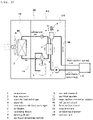
Fig. 1 is a block diagram of a heat medium circulation system in a first embodiment; -
Fig. 2 is a sectional view of a gas-liquid separating portion in the first embodiment; -
Fig. 3 is a perspective view of the gas-liquid separating portion in the first embodiment; -
Fig. 4 is a sectional view of a gas-liquid separating portion in a second embodiment; -
Fig. 5 is a block diagram of a heat medium circulation system in the second embodiment; and -
Fig. 6 is a perspective view of the gas-liquid separating portion in the second embodiment. - Embodiments will be described in detail below with reference to the drawings. However, excessively detailed description more than necessary will be omitted in some cases. For example, detailed description of already well known matters, or redundant description of substantially the same configuration will be omitted in some cases. This is for preventing the following description becoming redundant more than necessary, and for making it easy for a person skilled in the art to understand.
- The accompanying drawing and the following description are provided so that the person skilled in the art can sufficiently understand the present disclosure, and it is not intended that they limit the subject matter described in claims.
- A first embodiment will be described below using
Figs. 1 to 3 . - In
Fig. 1 , a heatmedium circulation system 20 is composed of anoutdoor unit 80 and a use-side terminal 10. The heatmedium circulation system 20 includes arefrigerant circuit 40 and aheat medium circuit 50. - The
refrigerant circuit 40 is a vapor compression type refrigeration cycle. Therefrigerant circuit 40 is configured by connecting acompressor 1, a use-side heat exchanger 3, anexpander 4 and a heat source-side heat exchanger 5 to one another through refrigerant pipe. Propane which is flammable refrigerant is used as refrigerant. The propane is heavier than air, and stays at a low position. - The refrigerant which flows through the
refrigerant circuit 40 may be R1234yf, R1234ze and R32 which are mildly flammable refrigerants. - The
refrigerant circuit 40 is provided with a four-way valve 2 which switches between a heating operation and a cooling operation. In the heating operation, warm water which is heat medium is produced. In the cooling operation, cold water which is heat medium is produced. Anair blower 6 for generating air which passes through the heat source-side heat exchanger 5 is provided. - The
heat medium circuit 50 is configured by sequentially connecting, to one another, aconveying device 7 which is a conveying pump, the use-side heat exchanger 3, a gas-liquid separatingportion 9 and the use-side terminal 10 which is a heating or cooling terminal. Theheat medium circuit 50 uses water or antifreeze liquid as the heat medium. - The
refrigerant circuit 40 and theheat medium circuit 50 excluding the use-side terminal 10 are accommodated in theoutdoor unit 80. Thecompressor 1, the four-way valve 2, the use-side heat exchanger 3, theexpander 4, theconveying device 7, the use-side heat exchanger 3 and the gas-liquid separatingportion 9 are accommodated in amachine room 60 in theoutdoor unit 80. - The
air blower 6 and the heat source-side heat exchanger 5 are accommodated in an air-blowingchamber 70 in theoutdoor unit 80. Themachine room 60 and the air-blowingchamber 70 are partitioned from each other by a partitioningplate 11. - Here, the gas-liquid separating
portion 9 has a function to flow, into the separatingportion 9, gas phase refrigerant which leaks from at least therefrigerant circuit 40 into theheat medium circuit 50, and to separate the gas phase refrigerant and liquid phase heat medium from each other. In the gas-liquid separatingportion 9, air which is mixed into the liquid phase heat medium can also separate from the liquid phase heat medium. - That is, when a crack is generated in a heat transfer bulkhead of the use-
side heat exchanger 3 by a pinhole or repeated pressure variation, gas phase refrigerant which leaks from therefrigerant circuit 40 into theheat medium circuit 50 is pulled out from theheat medium circuit 50 and separated from liquid phase heat medium. The gas-liquid separatingportion 9 is placed at the highest position of theheat medium circuit 50. - An
ejecting device 8 which ejects at least gas phase refrigerant separated in the gas-liquid separatingportion 9 is connected to an upper side of the gas-liquid separatingportion 9. - In
Fig. 2 , if gas phase component of refrigerant is mixed in heat medium which flows out from the use-side heat exchanger 3 in theheat medium circuit 50, liquid phase heat medium and gas phase refrigerant are separated from each other in the gas-liquid separatingportion 9. If the gas phase refrigerant flows into theejecting device 8, afloat 8a provided in the ejectingdevice 8 is pushed down, and the gas phase refrigerant is discharged outside. - An
inflow pipe 9b through which at least heat medium flows into the gas-liquid separatingportion 9 and anoutflow pipe 9c through which heat medium flows out from the gas-liquid separatingportion 9 are connected to the gas-liquid separatingportion 9. A position where at least the heat medium flows into the gas-liquid separatingportion 9 is located lower than a position where heat medium flows out from the gas-liquid separatingportion 9. - A position of a heat medium outlet pipe of the use-
side heat exchanger 3 of theheat medium circuit 50 and a position of theinflow pipe 9b of the gas-liquid separatingportion 9 are located substantially at the same height. - A
divider plate 9f is placed in the gas-liquid separatingportion 9 such that thedivider plate 9f is opposed to the position where at least the heat medium flows into the gas-liquid separatingportion 9. - An upper end of the
divider plate 9f is located higher than the position where the heat medium flows out from the gas-liquid separatingportion 9. - In
Fig. 3 , a plurality ofopenings 9a are provided in thedivider plate 9f. The plurality ofopenings 9a are located at positions higher than a position where the heat medium flows out from the gas-liquid separatingportion 9. - Action and effect of the heat
medium circulation system 20 having the above-described configuration will be described. - First, action of the
heat medium circuit 50 of the heatmedium circulation system 20 will be described usingFigs. 1 and2 . According to the outline, refrigerant which flows out from the use-side heat exchanger 3 leaks into heat medium before the refrigerant flows into the use-side terminal 10, the heat medium flows into the gas-liquid separating portion 9, liquid phase component and gas phase component are separated from each other, and the separated gas phase component (refrigerant) is discharged and dispersed through the ejectingdevice 8. - Operations for cooling or heating heat medium is carried out by the use-
side heat exchanger 3 of the heatmedium circulation system 20. In these operations, when a pinhole or a crack is generated in the heat transfer bulkhead which divides a flow path of refrigerant and a flow path of heat medium of the use-side heat exchanger 3, refrigerant of therefrigerant circuit 40 leaks into theheat medium circuit 50. Therefore, at an outlet of theheat medium circuit 50 of the use-side heat exchanger 3, gas phase refrigerant is mixed into liquid phase heat medium (mixed phase flowing state). - The mixed phase flow of the liquid phase heat medium and the gas phase refrigerant which flow out from the outlet of the
heat medium circuit 50 of the use-side heat exchanger 3 flows in in a horizontal direction from theinflow pipe 9b which is located on a lower portion of the gas-liquid separating portion 9. - The mixed phase flow collides against the
divider plate 9f which is placed such that it is opposed to a position where the mixed phase flow flows into the gas-liquid separating portion 9, and the mixed phase flow rises on a side where theinflow pipe 9b is connected to a region divided by thedivider plate 9f. - Hence, velocity component of the mixed phase flow in the horizontal direction is deleted and velocity component thereof is directed in the vertically upward direction. Further, buoyancy of gas phase refrigerant is also added, and the refrigerant rises, together with liquid phase heat medium, toward an upper portion of the gas-
liquid separating portion 9 where theejecting device 8 is placed. - A portion of bubble state refrigerant which reaches the upper portion of the gas-
liquid separating portion 9 moves to theejecting device 8 as it is, the other bubble state refrigerant collides against an upper surface of the gas-liquid separating portion 9, and ascending flow velocity of the other bubble state refrigerant becomes zero. - A bubble group formed from a large number of fine bubble state refrigerants is prone to stay in the upper portion of the gas-
liquid separating portion 9, and only gas phase refrigerant gradually flows into theejecting device 8 through an ejectingpipe 9d. - If gas phase refrigerants of more than a predetermined amount flow into the
ejecting device 8, thefloat 8a is pushed down and a valve portion (not shown) opens, and the gas phase refrigerant is discharged outside. - Further, since the upper end of the
divider plate 9f is located higher than the position where liquid phase heat medium flows out from the gas-liquid separating portion 9, the bubble group of refrigerant does not flow out from theoutflow pipe 9c before the bubble group reaches the upper portion of the gas-liquid separating portion 9. - In
Fig. 3 , the plurality ofopenings 9a are provided in thedivider plate 9f. The plurality ofopenings 9a are located higher than the position where heat medium flows out from the gas-liquid separating portion 9. Therefore, since the bubble group of refrigerant which is mixed in liquid phase heat medium collides against thedivider plate 9f, the bubble group of refrigerant does not flow out directly from theoutflow pipe 9c. - According to this, liquid phase heat medium having no bubbles rises on the side of the
inflow pipe 9b divided by thedivider plate 9f due to buoyancy and inertia force, but the liquid phase heat medium passes through theopenings 9a of thedivider plate 9f having small flowing resistance and moves to theoutflow pipe 9c rather than going around the upper end of thedivider plate 9f. - At that time, since the position of the
outflow pipe 9c is lower than the position of theopenings 9a, the bubble group of refrigerant does not reach theoutflow pipe 9c due to effect of buoyancy of the bubbles themselves, and the bubble group of refrigerant rises upward of the gas-liquid separating portion 9. - That is, the gas phase refrigerant does not pass through the
openings 9a, and only the liquid phase heat medium passes through theopenings 9a and reaches theoutflow pipe 9c. - As described above, in the embodiment, the heat medium circulation system 20 including: the refrigerant circuit 40 to which the compressor 1, the use-side heat exchanger 3, the expander 4 and the heat source-side heat exchanger 5 are connected and through which refrigerant circulates; the air blower 6 for generating air which passes through the heat source-side heat exchanger 5; the heat medium circuit 50 through which liquid phase heat medium cooled or heated by the use-side heat exchanger 3 circulates by refrigerant discharged from the compressor 1 through the use-side terminal 9; the conveying device 7 provided in the heat medium circuit 50 for circulating heat medium; the gas-liquid separating portion 9 provided in the heat medium circuit 50 downstream of the use-side heat exchanger 3 and upstream of the use-side terminal 10 for separating refrigerant which leaks at least into the heat medium circuit 50 from heat medium; and the ejecting device 8 connected to the gas-liquid separating portion 9 for discharging at least refrigerant separated in the gas-liquid separating portion 9 to outside, wherein the inflow pipe 9b through which at least heat medium flows into the gas-liquid separating portion 9 and the outflow pipe 9c through which heat medium flows out from the gas-liquid separating portion 9 are connected to the gas-liquid separating portion 9, a position where at least heat medium flows into the gas-liquid separating portion 9 is located lower than a position where the heat medium flows out from the gas-liquid separating portion 9.
- According to this, the position where at least the heat medium flows into the gas-
liquid separating portion 9 is lower than the position where heat medium flows out from the gas-liquid separating portion 9. Therefore, as the bubble group formed from the large number of fine bubble state refrigerant floats in the gas-liquid separating portion 9, diameters of the bubbles become large. - Therefore, rising speed of bubble group is accelerated by increase of buoyancy of the bubble group, only liquid phase heat medium flows out from the
outflow pipe 9c, and a moving distance of the liquid phase heat medium becomes short. Therefore, gas-liquid separating performance of the gas-liquid separating portion 9 can be enhanced. - The gas-
liquid separating portion 9 is located at the highest position of theheat medium circuit 50, but theinflow pipe 9b of the gas-liquid separating portion 9 is connected to a location close to the lower surface of the gas-liquid separating portion 9. Hence, a difference in height between the outlet of the use-side heat exchanger 3 on the side of theheat medium circuit 50 and the position where at least the heat medium flows into the gas-liquid separating portion 9 is small, and a length of the pipe also becomes short. - According to this, pressure loss and thermal loss caused by the pipe between the use-
side heat exchanger 3 and the gas-liquid separating portion 9 become small and as a result, power consumption of the conveyingdevice 7 and thecompressor 1 can be reduced. - The
divider plate 9f is placed in the gas-liquid separating portion 9 such that thedivider plate 9f is opposed to the position where at least the heat medium flows into the gas-liquid separating portion 9. - According to this, the bubble group formed from the large number of bubble state refrigerants which flow into the gas-
liquid separating portion 9 is prone to move upward and stay. Therefore, it is possible to prevent the bubble state refrigerant from flowing out toward the use-side terminal 10, and safety can be enhanced. - The upper end of the
divider plate 9f is located higher than the position where heat medium flows out from the gas-liquid separating portion 9. - According to this, after the mixed phase flow between liquid phase heat medium and gas phase refrigerant flows into the gas-
liquid separating portion 9, the bubble group formed from the large number of bubble state refrigerants is guided upward, and refrigerant is discharged outside through the ejectingdevice 8. In this process, it is possible to prevent that the refrigerant climbs over thedivider plate 9f before the bubble group reaches theejecting device 8 and the refrigerant flows out from the gas-liquid separating portion 9. - Therefore, since it is possible to prevent refrigerant from flowing out into the use-
side terminal 10, safety can be enhanced. - In the
divider plate 9f, theopenings 9a are provided at positions higher than the position where heat medium flows out from the gas-liquid separating portion 9. - According to this, gas phase refrigerant does not pass through the
openings 9a, and only liquid phase heat medium passes through theopenings 9a and reaches theoutflow pipe 9c. Therefore, it is possible to prevent refrigerant from flowing out from the gas-liquid separating portion 9. - Therefore, since it is possible to prevent refrigerant from flowing out into the use-
side terminal 10, safety can be enhanced. - From the above-described fact, even when refrigerant leaks from the
refrigerant circuit 40 through which refrigerant circulates to theheat medium circuit 50 through which heat medium circulates, it is possible to prevent refrigerant from staying in theheat medium circuit 50, and it is possible to provide the heatmedium circulation system 20 having excellent safety. - Especially, when refrigerant is flammable refrigerant, safety can further be enhanced. When refrigerant is propane, since propane is heavier than air and propane stays in a low position, the above-described effect becomes large.
- A second embodiment will be described below using
Figs. 4 to 6 . - The same action and effect as those in the first embodiment will be omitted, and different contents will mainly be described below.
- In
Fig. 4 , asuction port 9h of anoutflow pipe 9c through which heat medium flows out from a gas-liquid separating portion 9 is placed downward in a gas-liquid separating portion 9. - A side surface of the gas-
liquid separating portion 9 is obliquely formed such that a horizontal cross section area of the side surface becomes smaller upwardly. Anejecting device 8 is connected to the highest portion of the gas-liquid separating portion 9. - The ejecting
device 8 is connected to the gas-liquid separating portion 9 in the horizontal direction at a position closer to a position where heat medium flows into the gas-liquid separating portion 9 than a position where heat medium flows out from the gas-liquid separating portion 9. A discharging port is provided in the lowermost surface of the gas-liquid separating portion 9, and the discharging port is normally closed by a dischargingplug 9e. - In
Fig. 5 , the gas-liquid separating portion 9 of the second embodiment is different from the gas-liquid separating portion 9 of the first embodiment in that anexhaust pipe 8b is connected to theejecting device 8. Refrigerant at least in theejecting device 8 is discharged into the atmosphere or an air-blowingchamber 70 from theexhaust pipe 8b. - In
Fig. 6 , a plurality ofdivider plates 9f are placed in parallel to an interior of the gas-liquid separating portion 9. Depending upon a placing position of theoutflow pipe 9c, thedivider plates 9f may not be placed in parallel to the interior of the gas-liquid separating portion 9, and an angle may be provided between the plurality ofdivider plates 9f and thedivider plates 9f may be placed obliquely. - Actions and effects of a heat
medium circulation system 30 and the gas-liquid separating portion 9 having the above-described configurations will be described. - In
Fig. 4 , thesuction port 9h of theoutflow pipe 9c is downwardly placed in the gas-liquid separating portion 9. Therefore, even if gas phase refrigerant is included in heat medium, buoyancy is applied to the bubble group formed from fine bubble state refrigerants. Further, since thesuction port 9h is directed downwardly, it is possible to prevent that the bubble group from coming around from above and from flowing out into the use-side terminal 10 through thesuction port 9h. - The gas phase refrigerant flows into the
inflow pipe 9b of the gas-liquid separating portion 9 and is mixed into the heat medium. Thereafter, the gas phase refrigerant rises and temporality stays above the gas-liquid separating portion 9 as a bubble group formed from a large number of fine bubble state refrigerants. - A side surface of the gas-
liquid separating portion 9 is obliquely formed such that a horizontal cross section area of the side surface becomes smaller upwardly. Anejecting device 8 is connected to the highest portion of the gas-liquid separating portion 9. - The ejecting
device 8 is connected to the gas-liquid separating portion 9 in the horizontal direction at a position closer to a position where the heat medium flows into the gas-liquid separating portion 9 than a position where the heat medium flows out from the gas-liquid separating portion 9. - Hence, buoyancy of the bubbles becomes large due to friction resistance between a wall surface and the bubble group formed from the large number of fine bubble state refrigerants which stay in the upper portion of the gas-
liquid separating portion 9. The gas phase refrigerant at the highest position easily moves to the connection port of the ejectingpipe 9d located at the highest position, and the gas phase refrigerant easily flows into the ejectingpipe 9d which is connected to theejecting device 8. - A discharging port is provided in the lowermost surface of the gas-
liquid separating portion 9 , and the discharging port is normally closed by the dischargingplug 9e. Therefore, if the dischargingplug 9e is opened, heat medium which stays in the gas-liquid separating portion 9 can be released. - In
Fig. 5 , theexhaust pipe 8b is connected to theejecting device 8 such that refrigerant at least in theejecting device 8 is discharged into the atmosphere or the air-blowingchamber 70. Therefore, the discharged gas phase refrigerant does not come into contact with or encounter an ignition source such as electric parts or electrical contacts. Especially, if gas is discharged into the air-blowingchamber 70, gas phase refrigerant is dispersed by operating theair blower 6. - In
Fig. 6 , since the plurality ofdivider plates 9f are placed in the gas-liquid separating portion 9, it is possible to further enhance the gas-liquid separating performance in the gas-liquid separating portion 9. - In the embodiment, as described above, the
suction port 9h of theoutflow pipe 9c through which heat medium flows out from the gas-liquid separating portion 9 is downwardly placed in the gas-liquid separating portion 9. - According to this, it is possible to prevent the fine bubble state refrigerants from coming around from above and from flowing out into the use-
side terminal 10 through thesuction port 9h, and safety can be enhanced. - The side surface of the gas-
liquid separating portion 9 is obliquely formed such that the horizontal cross section area of the side surface becomes smaller upward. The ejectingdevice 8 is connected to the uppermost portion of the gas-liquid separating portion 9. - The ejecting
device 8 is connected to the gas-liquid separating portion 9 in the horizontal direction at a position closer to the position where the heat medium flows into the gas-liquid separating portion 9 than the position where the heat medium flows out from the gas-liquid separating portion 9. - According to this, buoyancy of bubbles becomes large by friction resistance between the wall surface and the bubble group formed from the large number of fine bubble state refrigerants which stay above the gas-
liquid separating portion 9. The gas phase refrigerant easily moves to the connection port of the ejectingpipe 9d which is located at the highest position, and the gas phase refrigerant easily flows into the ejectingpipe 9d connected to theejecting device 8. - The discharging port is provided in the lowermost surface of the gas-
liquid separating portion 9, and the discharging port is normally closed by the dischargingplug 9e. - According to this, when the heat medium is replaced at the time of the maintenance operation, heat medium remaining in the gas-
liquid separating portion 9 can easily be discharged. - The
exhaust pipe 8b is connected to theejecting device 8 such that refrigerant at least in theejecting device 8 is discharged into the atmosphere or the air-blowingchamber 70. - According to this, since discharged gas phase refrigerant does not come into contact with or encounter an ignition source such as electric parts or electric contacts, safety can further be enhanced.
- Especially if gas phase refrigerant is discharged into the air-blowing
chamber 70, the gas phase refrigerant is dispersed by the operation of theair blower 6. When the refrigerant is flammable refrigerant, safety can further be enhanced. - The plurality of
divider plates 9f are placed in the gas-liquid separating portion 9. According to this, it is possible to further enhance the gas-liquid separating performance of the gas-liquid separating portion 9. - By the above-described fact, even if refrigerant leaks from the
refrigerant circuit 40 through which refrigerant circulates to theheat medium circuit 50 through which heat medium circulates, it is possible to prevent refrigerant from staying in theheat medium circuit 50, and it is possible to provide the heatmedium circulation system 20 having excellent safety. - Especially when the refrigerant is flammable refrigerant, safety can further be enhanced. When refrigerant is propane, since propane is heavier than air and propane stays in a low position, the above-described effect becomes large.
- The above-described embodiments are for illustrating the present disclosure, and the embodiments can variously be changed replacement, added or omitted in the scope of the claims or equivalent scope.
- The present disclosure can be applied to a heat medium circulation system from which especially flammable refrigerant can leak in a heat medium circuit. More specifically, the patent document be applied to a heat pump liquid heating device and the like.
-
- 1
- compressor
- 2
- four-way valve
- 3
- use-side heat exchanger
- 4
- expander
- 5
- heat source-side heat exchanger
- 6
- air blower
- 7
- conveying device
- 8
- ejecting device8
- 8a
- float
- 8b
- exhaust pipe
- 9
- gas-liquid separating portion
- 9a
- openings
- 9b
- inflow pipe
- 9c
- outflow pipe
- 9d
- ejecting pipe
- 9e
- discharging plug
- 9f
- divider plate
- 9h
- suction port
- 10
- use-side terminal
- 11
- partitioning plate
- 20
- heat medium circulation system
- 30
- heat medium circulation system
- 40
- refrigerant circuit
- 50
- heat medium circuit
- 60
- machine room
- 70
- air-blowing chamber
- 80
- outdoor unit
Claims (9)
- A heat medium circulation system comprising: a refrigerant circuit (40) to which a compressor (1), a use-side heat exchanger (3), an expander (4) and a heat source-side heat exchanger (5) are connected and through which refrigerant circulates;an air blower (6) for generating air which passes through the heat source-side heat exchanger (5);a heat medium circuit (50) through which liquid phase heat medium cooled or heated by the use-side heat exchanger (3) circulates by the refrigerant discharged from the compressor (1) through a use-side terminal (10);a conveying device (7) provided in the heat medium circuit (50) for circulating the heat medium;a gas-liquid separating portion (9) provided in the heat medium circuit (50) downstream of the use-side heat exchanger (3) and upstream of the use-side terminal (10) for separating the refrigerant which leaks at least into the heat medium circuit (50) from the heat medium; andan ejecting device (8) connected to the gas-liquid separating portion (9) for discharging at least the refrigerant separated in the gas-liquid separating portion (9) to outside, whereinan inflow pipe (9b) through which at least the heat medium flows into the gas-liquid separating portion (9) and an outflow pipe (9c) through which the heat medium flows out from the gas-liquid separating portion (9) are connected to the gas-liquid separating portion (9), a position where at least the heat medium flows into the gas-liquid separating portion (9) is located lower than a position where the heat medium flows out from the gas-liquid separating portion (9).
- The heat medium circulation system according to claim 1, wherein a divider plate (9f) is placed in the gas-liquid separating portion (9) such that the divider plate (9f) is opposed to the position where at least the heat medium flows into the gas-liquid separating portion (9).
- The heat medium circulation system according to claim 2, wherein an upper end of the divider plate (9f) is located at a position higher than the position where the heat medium flows out from the gas-liquid separating portion (9).
- The heat medium circulation system according to claim 2 or 3, wherein in the divider plate (9f), an opening (9a) is provided at a position higher than the position where the heat medium flows out from the gas-liquid separating portion (9).
- The heat medium circulation system according to any one of claims 1 to 4, wherein a suction port (9h) of the outflow pipe (9c) through which the heat medium flows out from the gas-liquid separating portion (9) is downwardly placed in the gas-liquid separating portion (9).
- The heat medium circulation system according to any one of claims 1 to 5, wherein a side surface of the gas-liquid separating portion (9) is obliquely formed such that a cross section area of the gas-liquid separating portion (9) in a horizontal direction thereof becomes smaller upward, and the ejecting device (8) is connected to an uppermost portion of the gas-liquid separating portion (9).
- The heat medium circulation system according to any one of claims 1 to 6, wherein in a horizontal direction of the gas-liquid separating portion (9), the ejecting device (8) is connected to a position closer to the position where at least the heat medium flows into the gas-liquid separating portion (9) than the position where the heat medium flows out from the gas-liquid separating portion (9).
- The heat medium circulation system according to any one of claims 1 to 7, wherein a discharging port is provided in a lowermost surface of the gas-liquid separating portion (9).
- The heat medium circulation system according to any one of claims 1 to 8, further comprising an air-blowing chamber (70) where the air blower (6) is placed, wherein the refrigerant is a mildly flammable or flammable refrigerant, and an exhaust pipe (8b) is connected to the ejecting device (8) such that the refrigerant in at least the ejecting device (8) is discharged into an atmosphere or the air-blowing chamber (70) .
Applications Claiming Priority (1)
| Application Number | Priority Date | Filing Date | Title |
|---|---|---|---|
| JP2021023862A JP2022126030A (en) | 2021-02-18 | 2021-02-18 | Heat medium circulation system |
Publications (2)
| Publication Number | Publication Date |
|---|---|
| EP4047288A1 true EP4047288A1 (en) | 2022-08-24 |
| EP4047288B1 EP4047288B1 (en) | 2025-12-31 |
Family
ID=78598903
Family Applications (1)
| Application Number | Title | Priority Date | Filing Date |
|---|---|---|---|
| EP21207696.2A Active EP4047288B1 (en) | 2021-02-18 | 2021-11-11 | HEAT MEDIUM CIRCULATION SYSTEM |
Country Status (2)
| Country | Link |
|---|---|
| EP (1) | EP4047288B1 (en) |
| JP (1) | JP2022126030A (en) |
Cited By (7)
| Publication number | Priority date | Publication date | Assignee | Title |
|---|---|---|---|---|
| EP4345381A1 (en) * | 2022-09-30 | 2024-04-03 | Panasonic Intellectual Property Management Co., Ltd. | Heat pump cycle device |
| EP4378555A1 (en) * | 2022-11-30 | 2024-06-05 | Stiebel Eltron GmbH & Co. KG | Separator for use in a heat pump system |
| EP4386271A1 (en) * | 2022-12-15 | 2024-06-19 | Daikin Europe N.V. | Refrigeration cycle apparatus |
| EP4421394A1 (en) | 2023-02-23 | 2024-08-28 | Daikin Europe N.V. | Outdoor unit |
| EP4506626A1 (en) * | 2023-08-07 | 2025-02-12 | Vaillant GmbH | Degassing device |
| EP4560206A1 (en) * | 2023-11-22 | 2025-05-28 | Daikin Europe N.V. | Outdoor unit for a heat pump system |
| EP4575329A1 (en) * | 2023-12-22 | 2025-06-25 | Daikin Europe N.V. | Heat pump |
Families Citing this family (3)
| Publication number | Priority date | Publication date | Assignee | Title |
|---|---|---|---|---|
| EP4560205A1 (en) * | 2023-11-21 | 2025-05-28 | Daikin Europe N.V. | Outdoor unit for a heat pump system |
| WO2025210784A1 (en) * | 2024-04-03 | 2025-10-09 | 三菱電機株式会社 | Heat source unit and heat medium circulation system |
| JP2025174375A (en) | 2024-05-17 | 2025-11-28 | パナソニックIpマネジメント株式会社 | Internal components and gas-liquid separator |
Citations (3)
| Publication number | Priority date | Publication date | Assignee | Title |
|---|---|---|---|---|
| EP0027179A1 (en) * | 1979-09-13 | 1981-04-22 | Joh. Vaillant GmbH u. Co. | Pump with degasser |
| WO2018154628A1 (en) | 2017-02-21 | 2018-08-30 | 三菱電機株式会社 | Air conditioning device |
| WO2019239556A1 (en) * | 2018-06-14 | 2019-12-19 | 三菱電機株式会社 | Air conditioner |
Family Cites Families (16)
| Publication number | Priority date | Publication date | Assignee | Title |
|---|---|---|---|---|
| JPS55167454U (en) * | 1979-05-18 | 1980-12-02 | ||
| JPS59166805U (en) * | 1983-04-20 | 1984-11-08 | トキコ株式会社 | gas liquid separator |
| US4602923A (en) * | 1984-04-03 | 1986-07-29 | Erwin J. Baumgartler | Apparatus for degasifying a liquid medium |
| GB2231508B (en) * | 1989-04-26 | 1993-05-19 | Wardtec Ltd | Air separator in or for a fluid flow system |
| JP3183529B2 (en) * | 1991-06-27 | 2001-07-09 | 三菱電機株式会社 | Gas-liquid separator |
| JPH0542971U (en) * | 1991-11-01 | 1993-06-11 | シヤープ株式会社 | Refrigeration cycle |
| JPH1078275A (en) * | 1996-09-04 | 1998-03-24 | Showa Alum Corp | accumulator |
| JP3814729B2 (en) * | 1997-02-10 | 2006-08-30 | 株式会社竹中工務店 | Structure of liquid receiver in refrigeration cycle |
| JP4118254B2 (en) * | 2004-06-18 | 2008-07-16 | 三洋電機株式会社 | Refrigeration equipment |
| JP2007139347A (en) * | 2005-11-21 | 2007-06-07 | Daikin Ind Ltd | Refrigeration apparatus and method for installing the refrigeration apparatus |
| JP2009008349A (en) * | 2007-06-29 | 2009-01-15 | Daikin Ind Ltd | Gas-liquid separator |
| US8147575B2 (en) * | 2009-09-09 | 2012-04-03 | Ingersoll-Rand Company | Multi-stage oil separation system including a cyclonic separation stage |
| JP6085474B2 (en) * | 2012-12-25 | 2017-02-22 | 三菱重工業株式会社 | Gas-liquid separator and ship |
| JP5940489B2 (en) * | 2013-05-21 | 2016-06-29 | ジョンソンコントロールズ ヒタチ エア コンディショニング テクノロジー(ホンコン)リミテッド | Air conditioner |
| JP6601022B2 (en) * | 2015-07-07 | 2019-11-06 | アイシン精機株式会社 | Gas-liquid separator |
| CN109661546A (en) * | 2016-09-08 | 2019-04-19 | 三菱电机株式会社 | Heat pump assembly |
-
2021
- 2021-02-18 JP JP2021023862A patent/JP2022126030A/en active Pending
- 2021-11-11 EP EP21207696.2A patent/EP4047288B1/en active Active
Patent Citations (4)
| Publication number | Priority date | Publication date | Assignee | Title |
|---|---|---|---|---|
| EP0027179A1 (en) * | 1979-09-13 | 1981-04-22 | Joh. Vaillant GmbH u. Co. | Pump with degasser |
| WO2018154628A1 (en) | 2017-02-21 | 2018-08-30 | 三菱電機株式会社 | Air conditioning device |
| EP3587947A1 (en) * | 2017-02-21 | 2020-01-01 | Mitsubishi Electric Corporation | Air conditioning device |
| WO2019239556A1 (en) * | 2018-06-14 | 2019-12-19 | 三菱電機株式会社 | Air conditioner |
Cited By (7)
| Publication number | Priority date | Publication date | Assignee | Title |
|---|---|---|---|---|
| EP4345381A1 (en) * | 2022-09-30 | 2024-04-03 | Panasonic Intellectual Property Management Co., Ltd. | Heat pump cycle device |
| EP4378555A1 (en) * | 2022-11-30 | 2024-06-05 | Stiebel Eltron GmbH & Co. KG | Separator for use in a heat pump system |
| EP4386271A1 (en) * | 2022-12-15 | 2024-06-19 | Daikin Europe N.V. | Refrigeration cycle apparatus |
| EP4421394A1 (en) | 2023-02-23 | 2024-08-28 | Daikin Europe N.V. | Outdoor unit |
| EP4506626A1 (en) * | 2023-08-07 | 2025-02-12 | Vaillant GmbH | Degassing device |
| EP4560206A1 (en) * | 2023-11-22 | 2025-05-28 | Daikin Europe N.V. | Outdoor unit for a heat pump system |
| EP4575329A1 (en) * | 2023-12-22 | 2025-06-25 | Daikin Europe N.V. | Heat pump |
Also Published As
| Publication number | Publication date |
|---|---|
| EP4047288B1 (en) | 2025-12-31 |
| JP2022126030A (en) | 2022-08-30 |
Similar Documents
| Publication | Publication Date | Title |
|---|---|---|
| EP4047288B1 (en) | HEAT MEDIUM CIRCULATION SYSTEM | |
| EP3967943B1 (en) | Heat medium circulation system | |
| EP2998656B1 (en) | Air conditioner | |
| AU2014371155B2 (en) | Heat exchanger and air conditioning device | |
| US20160238322A1 (en) | Heat exchanger and air conditioning device | |
| JP6565272B2 (en) | Refrigeration unit heat source unit | |
| US20170292741A1 (en) | Heat exchanger and air conditioning apparatus | |
| JP5865529B1 (en) | Air conditioner | |
| JP2015068622A (en) | Heat exchanger and air conditioner | |
| JP2016191504A (en) | Refrigeration unit heat source unit | |
| CN112567193B (en) | Heat exchanger and air conditioner | |
| EP2597384B1 (en) | Outdoor unit for air conditioner | |
| KR20130043977A (en) | Oil separator and air conditioner comprising the same | |
| EP4443079A1 (en) | Heat medium circulation device | |
| US11175078B2 (en) | Gas-liquid separator and air conditioner including the same | |
| EP4345381A1 (en) | Heat pump cycle device | |
| KR102183547B1 (en) | Oil separator | |
| EP4325128A1 (en) | Heat medium circulation device | |
| EP4325129A1 (en) | Heat medium circulation device | |
| CN111750573B (en) | Heat exchanger flow divider | |
| EP4325130A1 (en) | Heat medium circulation device | |
| JP6878550B2 (en) | Refrigerator | |
| JP6340681B2 (en) | Refrigeration circuit | |
| EP4354045A1 (en) | Refrigeration cycle device | |
| CN115485517B (en) | Evaporator |
Legal Events
| Date | Code | Title | Description |
|---|---|---|---|
| PUAI | Public reference made under article 153(3) epc to a published international application that has entered the european phase |
Free format text: ORIGINAL CODE: 0009012 |
|
| STAA | Information on the status of an ep patent application or granted ep patent |
Free format text: STATUS: THE APPLICATION HAS BEEN PUBLISHED |
|
| AK | Designated contracting states |
Kind code of ref document: A1 Designated state(s): AL AT BE BG CH CY CZ DE DK EE ES FI FR GB GR HR HU IE IS IT LI LT LU LV MC MK MT NL NO PL PT RO RS SE SI SK SM TR |
|
| STAA | Information on the status of an ep patent application or granted ep patent |
Free format text: STATUS: REQUEST FOR EXAMINATION WAS MADE |
|
| 17P | Request for examination filed |
Effective date: 20230224 |
|
| RBV | Designated contracting states (corrected) |
Designated state(s): AL AT BE BG CH CY CZ DE DK EE ES FI FR GB GR HR HU IE IS IT LI LT LU LV MC MK MT NL NO PL PT RO RS SE SI SK SM TR |
|
| STAA | Information on the status of an ep patent application or granted ep patent |
Free format text: STATUS: EXAMINATION IS IN PROGRESS |
|
| 17Q | First examination report despatched |
Effective date: 20240502 |
|
| GRAP | Despatch of communication of intention to grant a patent |
Free format text: ORIGINAL CODE: EPIDOSNIGR1 |
|
| STAA | Information on the status of an ep patent application or granted ep patent |
Free format text: STATUS: GRANT OF PATENT IS INTENDED |
|
| RIC1 | Information provided on ipc code assigned before grant |
Ipc: F25B 49/00 20060101ALN20250527BHEP Ipc: F24F 11/36 20180101ALI20250527BHEP Ipc: F24D 19/08 20060101ALI20250527BHEP Ipc: F24D 3/18 20060101ALI20250527BHEP Ipc: B01D 19/00 20060101ALI20250527BHEP Ipc: F25B 13/00 20060101AFI20250527BHEP |
|
| INTG | Intention to grant announced |
Effective date: 20250620 |
|
| GRAS | Grant fee paid |
Free format text: ORIGINAL CODE: EPIDOSNIGR3 |
|
| RIN1 | Information on inventor provided before grant (corrected) |
Inventor name: AOYAMA, SHIGEO Inventor name: YAMAOKA, YUKI Inventor name: MORIWAKI, SHUNJI Inventor name: YOSHIDA, JUN Inventor name: NAKATANI, KAZUHITO |
|
| GRAA | (expected) grant |
Free format text: ORIGINAL CODE: 0009210 |
|
| STAA | Information on the status of an ep patent application or granted ep patent |
Free format text: STATUS: THE PATENT HAS BEEN GRANTED |
|
| AK | Designated contracting states |
Kind code of ref document: B1 Designated state(s): AL AT BE BG CH CY CZ DE DK EE ES FI FR GB GR HR HU IE IS IT LI LT LU LV MC MK MT NL NO PL PT RO RS SE SI SK SM TR |
|
| REG | Reference to a national code |
Ref country code: CH Ref legal event code: F10 Free format text: ST27 STATUS EVENT CODE: U-0-0-F10-F00 (AS PROVIDED BY THE NATIONAL OFFICE) Effective date: 20251231 Ref country code: GB Ref legal event code: FG4D |
|
| REG | Reference to a national code |
Ref country code: DE Ref legal event code: R096 Ref document number: 602021045361 Country of ref document: DE |
|
| REG | Reference to a national code |
Ref country code: IE Ref legal event code: FG4D |
|
| REG | Reference to a national code |
Ref country code: LT Ref legal event code: MG9D |
|
| PG25 | Lapsed in a contracting state [announced via postgrant information from national office to epo] |
Ref country code: NO Free format text: LAPSE BECAUSE OF FAILURE TO SUBMIT A TRANSLATION OF THE DESCRIPTION OR TO PAY THE FEE WITHIN THE PRESCRIBED TIME-LIMIT Effective date: 20260331 |
|
| PG25 | Lapsed in a contracting state [announced via postgrant information from national office to epo] |
Ref country code: HR Free format text: LAPSE BECAUSE OF FAILURE TO SUBMIT A TRANSLATION OF THE DESCRIPTION OR TO PAY THE FEE WITHIN THE PRESCRIBED TIME-LIMIT Effective date: 20251231 Ref country code: FI Free format text: LAPSE BECAUSE OF FAILURE TO SUBMIT A TRANSLATION OF THE DESCRIPTION OR TO PAY THE FEE WITHIN THE PRESCRIBED TIME-LIMIT Effective date: 20251231 |
|
| PG25 | Lapsed in a contracting state [announced via postgrant information from national office to epo] |
Ref country code: RS Free format text: LAPSE BECAUSE OF FAILURE TO SUBMIT A TRANSLATION OF THE DESCRIPTION OR TO PAY THE FEE WITHIN THE PRESCRIBED TIME-LIMIT Effective date: 20260331 |
|
| PG25 | Lapsed in a contracting state [announced via postgrant information from national office to epo] |
Ref country code: LV Free format text: LAPSE BECAUSE OF FAILURE TO SUBMIT A TRANSLATION OF THE DESCRIPTION OR TO PAY THE FEE WITHIN THE PRESCRIBED TIME-LIMIT Effective date: 20251231 |