EP4047263B1 - Beleuchtungsvorrichtung - Google Patents
Beleuchtungsvorrichtung Download PDFInfo
- Publication number
- EP4047263B1 EP4047263B1 EP20911443.8A EP20911443A EP4047263B1 EP 4047263 B1 EP4047263 B1 EP 4047263B1 EP 20911443 A EP20911443 A EP 20911443A EP 4047263 B1 EP4047263 B1 EP 4047263B1
- Authority
- EP
- European Patent Office
- Prior art keywords
- positioning member
- light guide
- housing
- section
- lighting device
- Prior art date
- Legal status (The legal status is an assumption and is not a legal conclusion. Google has not performed a legal analysis and makes no representation as to the accuracy of the status listed.)
- Active
Links
Images


Classifications
-
- G—PHYSICS
- G02—OPTICS
- G02B—OPTICAL ELEMENTS, SYSTEMS OR APPARATUS
- G02B6/00—Light guides; Structural details of arrangements comprising light guides and other optical elements, e.g. couplings
- G02B6/0001—Light guides; Structural details of arrangements comprising light guides and other optical elements, e.g. couplings specially adapted for lighting devices or systems
- G02B6/0011—Light guides; Structural details of arrangements comprising light guides and other optical elements, e.g. couplings specially adapted for lighting devices or systems the light guides being planar or of plate-like form
- G02B6/0081—Mechanical or electrical aspects of the light guide and light source in the lighting device peculiar to the adaptation to planar light guides, e.g. concerning packaging
- G02B6/0086—Positioning aspects
- G02B6/0088—Positioning aspects of the light guide or other optical sheets in the package
-
- G—PHYSICS
- G02—OPTICS
- G02B—OPTICAL ELEMENTS, SYSTEMS OR APPARATUS
- G02B6/00—Light guides; Structural details of arrangements comprising light guides and other optical elements, e.g. couplings
- G02B6/0001—Light guides; Structural details of arrangements comprising light guides and other optical elements, e.g. couplings specially adapted for lighting devices or systems
- G02B6/0011—Light guides; Structural details of arrangements comprising light guides and other optical elements, e.g. couplings specially adapted for lighting devices or systems the light guides being planar or of plate-like form
- G02B6/0075—Arrangements of multiple light guides
- G02B6/0078—Side-by-side arrangements, e.g. for large area displays
-
- G—PHYSICS
- G02—OPTICS
- G02B—OPTICAL ELEMENTS, SYSTEMS OR APPARATUS
- G02B6/00—Light guides; Structural details of arrangements comprising light guides and other optical elements, e.g. couplings
- G02B6/0001—Light guides; Structural details of arrangements comprising light guides and other optical elements, e.g. couplings specially adapted for lighting devices or systems
- G02B6/0011—Light guides; Structural details of arrangements comprising light guides and other optical elements, e.g. couplings specially adapted for lighting devices or systems the light guides being planar or of plate-like form
- G02B6/0081—Mechanical or electrical aspects of the light guide and light source in the lighting device peculiar to the adaptation to planar light guides, e.g. concerning packaging
- G02B6/0095—Light guides as housings, housing portions, shelves, doors, tiles, windows, or the like
Definitions
- the present invention relates to a lighting device, and in particular, to a lighting device that is easy to assemble.
- some lighting devices have a light source module configured in a housing, and the light guide module is suspended below the housing.
- the suspended lighting devices often causes the light guide module to disengage from the housing due to shaking or collision during transportation.
- some lighting devices have a plurality of openings on the light source module, so that positioning posts can pass through the housing and the plurality of openings to prevent the light guide module from falling.
- this configuration will cause shadows in the area adjacent to the positioning posts, and additional openings on the light source module will also increase manufacturing time and costs.
- the Document US20160356436A1 discloses a kit for retrofitting a lighting fixture housing, the kit includes: a light guide; a plurality of light emitting diodes; a mounting system including a member configured for connecting to the lighting fixture housing and to dispose the plurality of light emitting diodes for coupling light edgewise into the light guide so that the coupled light emits from the light guide to provide illumination; and a light emitting diode driver configured for attaching to the lighting fixture housing to power the plurality of light emitting diodes while an existing ballast remains mounted to the lighting fixture frame.
- the Document CN107068009A discloses a hoisted fire-fighting indicator, including: a bin box, a line-locking buckle, end cover plates, a circuit board, a pin shaft and a light guide plate; wherein a flanging groove is formed in the bin box, the upper portion of the bin box is provided with a line-cross hole, and the line-locking buckle is installed in the line-cross hole of the bin box; the circuit board is arranged in a middle groove in the bin box; the light guide plate is hung on a turn-up edge in the bin box through the pin shaft, and the light guide plate is printed with an indication pattern; the two ends of the bin box are provided with the end cover plates, the end cover plates are fixed in internally-curled semicircular holes in the bin box, and hoisting holes are formed in the end cover plates.
- the Document CN208504144U discloses a ceiling lamp including an appearance profile, wherein a wing is provide on each of two sides om top of the appearance profile, a sliding chute is provided on an inner side of the wing, a fitting I and a fitting II are clamped within the sliding chute, and the light guide plate are inserted into the lower surface of the wings on the two sides of the appearance profile.
- the invention provides a lighting device according the appended claims, that is easy to assemble.
- the lighting device comprises a housing, a light source module, a light guiding module, and a positioning member.
- the housing includes an accommodating space.
- the accommodating space elongates along a length direction of the housing and has an opening facing downwardly.
- the light source module is disposed in the accommodating space.
- the light guiding module is configured to receive the light emitted from the light source module, and the light guiding module includes at least two light guide plates extending along a downward direction to outside of the opening.
- the positioning member is slidably disposed in the accommodating space of the housing.
- the two light guide plates are inserted into the accommodating space of the housing from opposite sides of the housing along the length direction of the housing and are coupled to the opposite sides of the positioning member, so that the positioning member supports and positions the two light guide plates.
- the accommodating space of the housing has a first passage and a second passage.
- the second passage is located between the first passage and the opening and communicates with each other.
- the light source module is disposed in the first passage of the accommodating space.
- the positioning member is located in the second passage of the accommodating space.
- the housing has a first section, a second section, and a third section.
- the second section is connected between the first section and the third section, and the first section and the second section restrict the movement of the positioning member along the second passage.
- the first section surrounds and defines the opening of the accommodating space.
- the second section surrounds and defines the second passage of the accommodating space, and the third section surrounds and defines the first passage of the accommodating space.
- the positioning member further includes at least two first convex portions for abutting against the first section.
- the positioning member further includes at least two second convex portions for abutting against the third section.
- the first convex portion and the second convex portion are extended in the opposite directions.
- the housing is extended along a long axis to form a length and forms a width along a short axis.
- the short axis and the long axis are perpendicular to each other.
- the positioning member is formed with two first notches. The two first notches are symmetrical to the short axis, and each of the two light guide plates has a depression portion to be engaged with the corresponding first notch.
- the housing forms a height along a central axis.
- the central axis is perpendicular to the short axis and the long axis, and the dimension of the depression portion along the central axis is greater than a thickness of the positioning member.
- the depression portion has an upper surface and a lower surface.
- the upper surface abuts against a top surface of the positioning member, and the bottom surface of the positioning member does not abut against the lower surface.
- the positioning member further includes two first guiding inclined surfaces which guide each of the light guide plates into the corresponding first notch.
- the housing is extended along a long axis to form a length and forms a width along a short axis.
- the short axis and the long axis are perpendicular to each other.
- the positioning member is formed with two first notches and two second notches. The two second notches communicate with the first notches.
- Each of the two light guide plates has a depression portion to be engaged with the corresponding second notch.
- the dimension of the light guide plates along the short axis is greater than the dimension of the first notch along the short axis.
- the positioning member further includes two second guiding inclined surfaces, which guide each of the light guide plates into the corresponding second notch.
- the lighting device further includes two fixing elements.
- Each of the fixing elements pass through the housing and the corresponding light guide plate, so that the light guide plates are fixed to the housing.
- the lighting device comprises a housing, a positioning member, and two light guide plate.
- the positioning member can be made of metal materials, and is slidably disposed in the accommodating space.
- the light guide plate can engage with the opposite sides of the positioning member. Since the light guide plate abuts against the top surface of the positioning member at the same time, the distance between the light guide plate and the light source module is equal, so that the lighting device can have better optical efficiency.
- the design of the invention can prevent from deformation or affecting optical characteristics caused by the collision of the expanded light guide plates.
- the components for fixing the light guide plates can be greatly reduced, so that reducing costs is achievable.
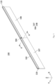
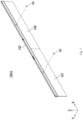
- Fig. 1 is a schematic structural diagram showing a lighting device 100 in accordance with an embodiment of this invention
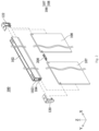
- Fig. 2 is a schematic exploded view showing the lighting device 100 in accordance with an embodiment of this invention.
- the lighting device 100 comprises a housing 102, a light source module 104, a light guiding module 106, a positioning member 200, and two covers 120, 122.
- the housing 102 is extended along the X-axis to form a length, and is extended along the Y-axis to form a width.
- the housing 102 has an accommodating space 1021, and the light source module 104 is disposed in the accommodating space 1021 to emit light.
- the light guide module 106 is configured to receive the light emitted from the light source module 104, and the light guide module 106 includes at least two light guide plates (light guide plate 107 and light guide plate 108).
- the positioning member 200 slidably enters the housing 102 from one side of the housing 102, and is disposed in the accommodating space 1021 of the housing 102. Then, the light guide plates 107, 108 enter the housing 102 from the opposite sides of the housing 102, so that the light guide plate 107 and the light guide plate 108 can be disposed in the accommodating space 1021 of the housing 102.
- the light guide plate 107 and the light guide plate 108 are coupled to the opposite sides of the positioning member 200, so that the positioning member 200 supports and positions the two light guide plates 107, 108.
- the positioning member 200 it is also possible to install one side of the positioning member 200 on either the light guide plate 107 or the light guide plate 108, so that the positioning member 200 can enter into the accommodation space 1021 along with the light guide plate. Then, the other light guide plate 107 or the light guide plate 108 is coupled to the other side of the positioning member 200, and the positioning member 200 can also be used to support and positions the light guide plate 107 and the light guide plate 108.
- the two covers 120, 122 are configured to cover the opposite sides of the housing 102, and are engaged with the light guide plate 107 and the light guide plate 108 to prevent the light guide plate 107 and the light guide plate 108 from disengaging from the housing 102.
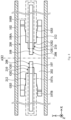
- Fig. 3 is a schematic partial structural diagram showing a positioning member 200, a light guide plate 107, and a light guide plate 108 in accordance with an embodiment of this invention.
- Fig. 4 is a partial top view showing the housing 102, the positioning member 200, and a light guiding module 106 in accordance with an embodiment of this invention. As shown in Figs. 3 and 4 , the light guide plate 107 and the light guide plate 108 are engaged with the opposite sides of the positioning member 200.
- the positioning member 200 includes a body 202, two first convex portions 204, and two second convex portions 206.
- the body 202 has a generally H-shaped structure, and the two first convex portions 204 and the two second convex portions 206 are extended from the body 202 along the Z-axis.
- the housing 102 can be extended along a long axis AX1 (parallel to the X-axis), and can be extended along a short axis AX2 (parallel to the Y-axis).
- the short axis AX2 and the long axis AX1 are perpendicular to each other.
- the positioning member 200 When viewed along the Z-axis (the short axis AX2 is regarded as the X-axis, and the long axis AX1 is regarded as the Y-axis), the positioning member 200 is formed with four supporting points, in which the upper left corner (second quadrant) faces down, the lower left corner (third quadrant) faces up, the upper right corner (first quadrant) faces up, and the lower right corner (fourth quadrant) faces down.
- the positioning member 200 can be formed with two first notches 208.
- the two first notches 208 are symmetrical to the short axis AX2, and as shown in Fig. 3 , the light guide plate 107 and the light guide plate 108 have a depression portion 1071 and a depression portion 1081 respectively.
- the depression portion 1071 and the depression portion 1081 are configured to be engaged with the corresponding first notches 208.
- the positioning member 200 may further include at least two first guiding inclined surfaces GS1 which are configured to guide the light guide plate 107 and the light guide plate 108 into the corresponding first notches 208.
- the positioning member 200 of the invention can match the light guide modules of different sizes.
- the positioning member 200 may be further formed with two second notches 210 and two third notches 212.
- the second notches 210 communicate with the first notches 208, and the third notches 212 communicate with the second notches 210.
- the second notches 210 may correspond to two light guide plates 107A, 108A with larger dimension, so that the light guide plates 107A, 108A can be engaged with the corresponding second notches 210. Since the dimension of the light guide plates 107A, 108A along the short axis AX2 is greater than the dimension of the first notch 208 along the short axis AX2, it can prevent a thicker light guide plate from being inserted into the smaller first notch 208. Therefore, the goal of the error proofing can be achieved in the invention. Furthermore, the positioning member 200 further includes at least two second guiding inclined surfaces GS2 which are configured to guide the light plates 107A, 108A into the corresponding second notches 210.
- the third notches 212 may correspond to the two light guide plates 107B and 108B with more larger dimension, so that the light guide plates 107B and 108B can be engaged with the corresponding third notches 212.
- the positioning member 200 further includes at least two third guiding inclined surfaces GS3 which are configured to guide the light plates 107B and 108B into the corresponding third notches 212.
- the light guide plates can be smoothly slid into the first notches 208, the second notches 210, and the third notches 212 according to their thickness of the various light guide plates, so that it can prevent the light guide plates from collision on the corner, and no damages will occur during the sliding process.
- FIG. 5 is an enlarged perspective view showing partial structure of the lighting device 100 in accordance with an embodiment of this invention.
- the housing 102 forms a height along a central axis AX3.
- the central axis AX3 is perpendicular to the short axis AX2 and the long axis AX1, and the dimension of the depression portions 1071, 1081 along the central axis AX3 is greater than a thickness of the positioning member 200.
- the depression portion 1071 has an upper surface 1072 and a lower surface 1073.
- the upper surface 1072 abuts against a top surface 200U of the positioning member 200, and a bottom surface 200L of the positioning member 200 does not abut against the lower surface 1073 of the positioning member 200.
- the upper surface 1082 of the depression portion 1081 abuts against the top surface 200U of the positioning member 200, and the bottom surface 200L of the positioning member 200 does not abut against the lower surface 1083 of the depression portion 1081.
- the upper surfaces 1072 and 1082 of the corresponding depression portions 1071 and 1081 serve as supporting surfaces to support the light guide plates 107, 108 when the light guide plates 107, 108 hang in the corresponding depression portions 1071, 1081.
- the supporting stability of the light guide plates 107, 108 can be improved.
- the distance between the light guide plate 107 and the light-emitting elements 1041 of the light source module 104 along the central axis AX3 is equal to the distance between the light guide plate 108 and the light-emitting elements 1041 of the light source module 104 along the central axis AX3. Therefore, the light emitted from the lighting device 100 can have a uniform brightness effect.
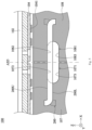
- FIG. 6 is a schematic cross-sectional view taken along line A-A' in Fig. 1 in accordance with an embodiment of this invention.
- the accommodating space 1021 of the housing 102 has a first passage 1023, a second passage 1024, and an opening 1025.
- the second passage 1024 is located between the first passage 1023 and the opening 1025, and communicates with each other.
- the light source module 104 is disposed in the first passage 1023 of the accommodating space 1021, and the positioning member 200 is located in the second passage 1024 of the accommodating space 1021.
- the light guide plate 108 is extended outside of the opening 1025.
- the positioning member 200 and the light source module 104 are located in different passages, the positioning member 200 will not affect or collide with the light source module 104 located in the first passage 1023 when the positioning member 200 is shifted in the second passage 1024. By the aforementioned design, it will help to prevent the damage of the light source module 104.
- the housing 102 has a first section 1026, a second section 1027, and a third section 1028.
- the second section 1027 is connected between the first section 1026 and the third section 1028.
- the first section 1026 and the second section 1027 are configured to restrict the movement of the positioning member 200 along the second passage 1024.
- the first section 1026 surrounds and defines the opening 1025 of the accommodating space 1021
- the second section 1027 surrounds and defines the second passage 1024 of the accommodating space 1021
- the third section 1028 surrounds and defines the first passage 1023 of the accommodating space 1021. Since the first passage 1023 and the second passage 1024 are separated by the third section 1028, the movement of the positioning member 200 in the second passage 1024 will not affect or collide with the light source module 104 located in the first passage 1023.
- first convex portion 204 is configured to abut against the first section 1026
- second convex portion 206 is configured to abut against the third section 1028.
- first convex portions 204 and the second convex portions 206 serve as four support points at four positions of left, right, up and down, and the positioning member 200 in the second passage 1024 can be firmly held by the first section 1026 and the third section 1028. Since the positioning member 200 can maintain a stable position in the second passage 1024, no deviation will occur.
- one side of the positioning member 200 can be installed on either the light guide plate 107 or the light guide plate 108, and is inserted into the accommodating space 1021, and then the other light guide plate 107 or the light guide plate 108 is coupled to the other side of the positioning member 200.
- the positioning member 200 still can be inserted into the depression portions 1071, 1081 smoothly due to the dimension of depression portions 1071, 1081 along the central axis AX3 is greater than a thickness of the positioning member 200. In such way, the light guide plate can be easily installed into the depression portions 1071, 1081, and there is no need for precise alignment and visual observation.
- the positioning member 200 since the positioning member 200 maintains a stable position in the second passage 1024 without deviations, the light guide plate can be assembled with the positioning member 200 in the correct position to avoid the misalignment of the light guide plate during assembling. Therefore, it can facilitate assembly accuracy and assembly efficiency.
- the lighting device 100A may further comprise two fixing elements 50.
- Each of the fixing elements 50 passes through the housing 102 and the corresponding light guide plate, so that the light guide plates 107, 108 are more securely fixed to the housing 102.
- the lighting device 100 includes a housing 102, a positioning member 200, and two light guide plates 107 and 108.
- the positioning member 200 can be made of metal materials and slidably disposed in the housing 102, and the light guide plates 107 and 108 can be clamped on the opposite sides of the positioning member 200. Since the light guide plates 107 and 108 abut against the top surface 200U of the positioning member 200 at the same time, the distance between the light guide plates 107 and 108 and the light source module 104 can be equal and well optical coupling, so that the lighting device 100 can have better optical efficiency.
- the positioning member 200 can move accordingly in accordance with the expansion. Therefore, the design of the invention can prevent from deformation or bad optical properties when the light guide plates 107 and 108 are expanded to squeeze and collide with each other.
- the components for fixing the light guide plates 107 and 108 can be greatly reduced to keep costs down.
Landscapes
- Physics & Mathematics (AREA)
- General Physics & Mathematics (AREA)
- Optics & Photonics (AREA)
- Planar Illumination Modules (AREA)
- Fastening Of Light Sources Or Lamp Holders (AREA)
Claims (13)
- Beleuchtungsvorrichtung (100, 100A), umfassend:ein Gehäuse, das sich entlang einer Längsrichtung (X) erstreckt und einen Aufnahmeraum (1021) mit einer nach unten gerichteten Öffnung (1025) aufweist;ein Lichtquellenmodul (104), das in dem Aufnahmeraum (1021) angeordnet ist;ein Lichtführungsmodul (106), das dazu konfiguriert ist, das von dem Lichtquellenmodul (104) emittierte Licht zu empfangen, wobei das Lichtführungsmodul (106) zwei Lichtführungsplatten (107, 108; 107A, 108A; 107B, 108B) umfasst, die sich entlang einer Abwärtsrichtung nach außerhalb der Öffnung (1025) erstrecken; undein Positionierungselement (200);wobei die beiden Lichtführungsplatten (107, 108; 107A, 108A; 107B, 108B) in den Aufnahmeraum (1021) des Gehäuses (102) von gegenüberliegenden Seiten des Gehäuses (102) entlang der Längsrichtung (X) des Gehäuses (102) eingeführt und mit den gegenüberliegenden Seiten des Positionierungselements (200) gekoppelt sind, so dass das Positionierungselement (200) die beiden Lichtführungsplatten (107, 108; 107A, 108A; 107B, 108B) stützt und positioniert;dadurch gekennzeichnet, dass das Positionierungselement (200) in dem Aufnahmeraum (1021) des Gehäuses (102) verschiebbar angeordnet ist.
- Beleuchtungsvorrichtung (100, 100A) nach Anspruch 1, wobei der Aufnahmeraum (1021) des Gehäuses (102) einen ersten Durchgang (1023) und einen zweiten Durchgang (1024) aufweist;
wobei der zweite Durchgang (1024) zwischen dem ersten Durchgang (1023) und der Öffnung (1025) angeordnet ist und diese miteinander in Verbindung stehen, das Lichtquellenmodul (104) in dem ersten Durchgang (1023) des Aufnahmeraums (1021) angeordnet ist und das Positionierungselement (200) in dem zweiten Durchgang (1024) des Aufnahmeraums (1021) angeordnet ist. - Beleuchtungsvorrichtung (100, 100A) nach Anspruch 2, wobei das Gehäuse (102) einen ersten Abschnitt (1026), einen zweiten Abschnitt (1027) und einen dritten Abschnitt (1028) aufweist, wobei der zweite Abschnitt (1027) zwischen dem ersten Abschnitt (1026) und dem dritten Abschnitt (1028) verbunden ist, und der erste Abschnitt (1026) und der zweite Abschnitt (1027) die Bewegung des Positionierungselements (200) entlang des zweiten Durchgangs (1024) einschränken;
wobei der erste Abschnitt (1026) die Öffnung (1025) des Aufnahmeraums (1021) umgibt und definiert, der zweite Abschnitt (1027) den zweiten Durchgang (1024) des Aufnahmeraums (1021) umgibt und definiert, und der dritte Abschnitt (1028) den ersten Durchgang (1023) des Aufnahmeraums (1021) umgibt und definiert. - Beleuchtungsvorrichtung (100, 100A) nach Anspruch 3, wobei das Positionierungselement (200) ferner mindestens zwei erste konvexe Abschnitte (204) zum Anliegen an dem ersten Abschnitt (1026) aufweist.
- Beleuchtungsvorrichtung (100, 100A) nach Anspruch 4, wobei das Positionierungselement (200) ferner mindestens zwei zweite konvexe Abschnitte (206) zum Anliegen an dem dritten Abschnitt aufweist.
- Beleuchtungsvorrichtung (100, 100A) nach Anspruch 5, wobei sich der erste konvexe Abschnitt (204) und der zweite konvexe Abschnitt (206) in entgegengesetzte Richtungen erstrecken.
- Beleuchtungsvorrichtung (100, 100A) nach einem der Ansprüche 1 bis 6, wobei sich das Gehäuse (102) entlang einer langen Achse (AX1) erstreckt, um eine Länge zu bilden, und entlang einer kurzen Achse (AX2) eine Breite bildet, wobei die kurze Achse (AX2) und die lange Achse (AX1) senkrecht zueinander stehen, wobei das Positionierungselement (200) mit zwei ersten Kerben (208) ausgebildet ist, wobei die zwei ersten Kerben (208) symmetrisch zu der kurzen Achse (AX2) sind, und wobei jede der zwei Lichtführungsplatten (107, 108; 107A, 108A; 107B, 108B) einen Vertiefungsabschnitt (1071, 1081) aufweist, der in die entsprechende erste Kerbe (208) eingreift.
- Beleuchtungsvorrichtung (100, 100A) nach Anspruch 7, wobei das Gehäuse (102) eine Höhe entlang einer Mittelachse (AX3) bildet, die Mittelachse (AX3) senkrecht zur kurzen Achse (AX2) und zur langen Achse (AX1) steht und die Abmessung des Vertiefungsabschnitts (1071, 1081) entlang der Mittelachse (AX3) größer ist als eine Dicke des Positionierungselements (200).
- Beleuchtungsvorrichtung (100, 100A) nach Anspruch 7 oder 8, wobei der Vertiefungsabschnitt (1071, 1081) eine obere Fläche (1072, 1082) und eine untere Fläche (1073, 1083) aufweist, die obere Fläche (1072, 1082) an einer Oberseite (200U) des Positionierungselements (200) anliegt und eine Unterseite (200L) des Positionierungselements (200) nicht an der unteren Fläche (1073, 1083) anliegt.
- Beleuchtungsvorrichtung (100, 100A) nach einem der Ansprüche 7 bis 9, wobei das Positionierungselement (200) ferner zwei erste geneigte Führungsflächen (GS1) aufweist, die jeweils die jeweiligen Lichtführungsplatten (107, 108; 107A, 108A; 107B, 108B) in die entsprechende erste Kerbe (208) führen.
- Beleuchtungsvorrichtung (100, 100A) nach einem der Ansprüche 1 bis 6, wobei sich das Gehäuse (102) entlang einer langen Achse (AX1) erstreckt, um eine Länge zu bilden, und entlang einer kurzen Achse (AX2) eine Breite bildet, wobei die kurze Achse (AX2) und die lange Achse (AX1) senkrecht zueinander stehen, wobei das Positionierungselement (200) mit zwei ersten Kerben (208) und zwei zweiten Kerben (210) ausgebildet ist, die beiden zweiten Kerben (210) mit den ersten Kerben (208) in Verbindung stehen, und wobei jede der zwei Lichtführungsplatten (107, 108; 107A, 108A; 107B, 108B) einen Vertiefungsabschnitt (1071, 1081) aufweist, der in die entsprechende zweite Kerbe (210) eingreift.
wobei die Abmessung der Lichtführungsplatten (107, 108; 107A, 108A; 107B, 108B) entlang der kurzen Achse (AX2) größer ist als die Abmessung der ersten Kerbe (208) entlang der kurzen Achse (AX2). - Beleuchtungsvorrichtung (100, 100A) nach Anspruch 11, wobei das Positionierungselement (200) ferner zwei zweite geneigte Führungsflächen (GS2) aufweist, die jeweils die jeweiligen Lichtführungsplatten (107, 108; 107A, 108A; 107B, 108B) in die entsprechende zweite Kerbe (210) führen.
- Beleuchtungsvorrichtung (100, 100A) nach einem der Ansprüche 1 bis 12, die ferner zwei Befestigungselemente (50) umfasst, wobei jedes der Befestigungselemente (50) durch das Gehäuse (102) und die entsprechende Lichtführungsplatte (107, 108; 107A, 108A; 107B, 108B) hindurchgeht, so dass die Lichtführungsplatten (107, 108; 107A, 108A; 107B, 108B) an dem Gehäuse (102) befestigt sind.
Applications Claiming Priority (1)
| Application Number | Priority Date | Filing Date | Title |
|---|---|---|---|
| PCT/CN2020/070468 WO2021138767A1 (zh) | 2020-01-06 | 2020-01-06 | 照明装置 |
Publications (4)
| Publication Number | Publication Date |
|---|---|
| EP4047263A1 EP4047263A1 (de) | 2022-08-24 |
| EP4047263A4 EP4047263A4 (de) | 2022-11-02 |
| EP4047263B1 true EP4047263B1 (de) | 2025-02-19 |
| EP4047263C0 EP4047263C0 (de) | 2025-02-19 |
Family
ID=76654550
Family Applications (1)
| Application Number | Title | Priority Date | Filing Date |
|---|---|---|---|
| EP20911443.8A Active EP4047263B1 (de) | 2020-01-06 | 2020-01-06 | Beleuchtungsvorrichtung |
Country Status (5)
| Country | Link |
|---|---|
| US (1) | US11150402B2 (de) |
| EP (1) | EP4047263B1 (de) |
| CN (1) | CN113366256B (de) |
| TW (1) | TWI728729B (de) |
| WO (1) | WO2021138767A1 (de) |
Families Citing this family (2)
| Publication number | Priority date | Publication date | Assignee | Title |
|---|---|---|---|---|
| WO2025024044A1 (en) * | 2023-07-27 | 2025-01-30 | Lumitex, Inc. | Channel spacer for a light guide |
| US12222539B1 (en) | 2023-07-27 | 2025-02-11 | Lumitex, Inc. | Channel spacer for a light guide |
Family Cites Families (19)
| Publication number | Priority date | Publication date | Assignee | Title |
|---|---|---|---|---|
| US6305109B1 (en) * | 1999-12-09 | 2001-10-23 | Chi-Huang Lee | Structure of signboard |
| DE10318160B4 (de) * | 2003-04-17 | 2006-11-30 | Dorma Gmbh + Co. Kg | Automatische Schiebetür |
| KR101071951B1 (ko) * | 2010-01-19 | 2011-10-11 | 한솔테크닉스(주) | 백라이트 유닛 |
| KR101993361B1 (ko) * | 2011-02-08 | 2019-06-26 | 지이 라이팅 솔루션스, 엘엘씨 | 광 조명 기구의 블레이드 |
| JP5396498B2 (ja) * | 2012-03-02 | 2014-01-22 | 株式会社エス・ケー・ジー | 発光装置 |
| CN104520633B (zh) * | 2012-08-28 | 2016-08-31 | 夏普株式会社 | 照明装置、显示装置以及电视接收装置 |
| TWI486686B (zh) * | 2013-01-11 | 2015-06-01 | Au Optronics Corp | 具導光板定位設計之背光模組 |
| US9423079B1 (en) * | 2013-07-05 | 2016-08-23 | Cooper Technologies Company | Method and system for retrofitting luminaires |
| TWI541471B (zh) * | 2014-11-20 | 2016-07-11 | Lamps and lanterns | |
| CN204372586U (zh) * | 2014-12-16 | 2015-06-03 | 连立华 | Led日光灯 |
| CN105650555B (zh) * | 2016-03-25 | 2018-06-19 | 安徽泽润光电有限公司 | Led面板灯及定位块 |
| KR101968295B1 (ko) * | 2016-07-11 | 2019-04-15 | (주)대호씨앤씨 | 방향 유도등 |
| CN206514095U (zh) * | 2017-02-23 | 2017-09-22 | 丽而康科技(深圳)有限公司 | 一种led面板灯 |
| CN107068009A (zh) * | 2017-06-21 | 2017-08-18 | 合肥木凡节能环保科技有限公司 | 一种吊装消防指示灯 |
| WO2019061027A1 (zh) * | 2017-09-26 | 2019-04-04 | 瑞仪光电(苏州)有限公司 | 照明装置 |
| CN208504144U (zh) * | 2018-06-27 | 2019-02-15 | 上海盛丽光电科技有限公司 | 一种低成本实现发光面长宽均可变的吊灯 |
| CN208566383U (zh) * | 2018-08-23 | 2019-03-01 | 中山市革创照明科技有限公司 | 一种易于生产的led洗墙灯 |
| CN209782518U (zh) * | 2019-05-07 | 2019-12-13 | 广州市宇亮灯饰电器制造有限公司 | 一种无边框的导光灯具 |
| US11073259B2 (en) * | 2019-08-30 | 2021-07-27 | Fluence Bioengineering, Inc. | Horticultural luminaire with a convex endcap |
-
2020
- 2020-01-06 CN CN202080002989.3A patent/CN113366256B/zh active Active
- 2020-01-06 WO PCT/CN2020/070468 patent/WO2021138767A1/zh not_active Ceased
- 2020-01-06 EP EP20911443.8A patent/EP4047263B1/de active Active
- 2020-03-04 TW TW109106991A patent/TWI728729B/zh active
-
2021
- 2021-01-06 US US17/142,777 patent/US11150402B2/en active Active
Also Published As
| Publication number | Publication date |
|---|---|
| WO2021138767A1 (zh) | 2021-07-15 |
| CN113366256B (zh) | 2022-09-13 |
| TWI728729B (zh) | 2021-05-21 |
| TW202127122A (zh) | 2021-07-16 |
| US11150402B2 (en) | 2021-10-19 |
| EP4047263C0 (de) | 2025-02-19 |
| US20210208331A1 (en) | 2021-07-08 |
| EP4047263A1 (de) | 2022-08-24 |
| CN113366256A (zh) | 2021-09-07 |
| EP4047263A4 (de) | 2022-11-02 |
Similar Documents
| Publication | Publication Date | Title |
|---|---|---|
| EP4047263B1 (de) | Beleuchtungsvorrichtung | |
| US20130294059A1 (en) | Led light fixture | |
| CA2810871C (en) | Light engine | |
| EP3738889B1 (de) | Beleuchtungsvorrichtung, flugzeug mit einer derartigen beleuchtungsvorrichtung und verfahren zur herstellung einer beleuchtungsvorrichtung | |
| US10508777B2 (en) | Light engine retrofit kit and method for installing same | |
| US10288269B2 (en) | Ceiling system | |
| US20180202637A1 (en) | Mounting system for light fixture | |
| CA2656394C (en) | Quick install canopy | |
| EP3026325A1 (de) | Nachrüstsatz für einbauleuchten und nachrüstungsverfahren | |
| EP1760516B1 (de) | Flüssigkristallanzeigevorrichtung | |
| US20200182437A1 (en) | Luminaire with Improved Assembly, Installation, and Wireless Functionality | |
| US20210285626A1 (en) | Mounting systems for luminaires | |
| JP7500047B2 (ja) | 照明装置 | |
| EP3798502B1 (de) | Plattenleuchte und kit mit der plattenleuchte | |
| US7331696B2 (en) | Method and apparatus for mounting a task light | |
| JP7549861B2 (ja) | 照明装置 | |
| JP2025028493A (ja) | 設備プレート及び照明システム | |
| CN222335246U (zh) | 便捷拆装的灯具 | |
| CN217082347U (zh) | 拼接组件、拼接装置、照明系统和轨道系统 | |
| RU2768240C1 (ru) | Светильник (варианты) | |
| JP2017092053A (ja) | 照明器具、光源部品および取付部品 | |
| JP2015181125A (ja) | 照明装置 | |
| CN223137764U (zh) | 一种弹性扣合式天花板灯具 | |
| CN216744218U (zh) | 一种上下发光灯具 | |
| EP3757452A1 (de) | Fahrzeuglichtstruktur |
Legal Events
| Date | Code | Title | Description |
|---|---|---|---|
| STAA | Information on the status of an ep patent application or granted ep patent |
Free format text: STATUS: THE INTERNATIONAL PUBLICATION HAS BEEN MADE |
|
| PUAI | Public reference made under article 153(3) epc to a published international application that has entered the european phase |
Free format text: ORIGINAL CODE: 0009012 |
|
| STAA | Information on the status of an ep patent application or granted ep patent |
Free format text: STATUS: REQUEST FOR EXAMINATION WAS MADE |
|
| 17P | Request for examination filed |
Effective date: 20220518 |
|
| AK | Designated contracting states |
Kind code of ref document: A1 Designated state(s): AL AT BE BG CH CY CZ DE DK EE ES FI FR GB GR HR HU IE IS IT LI LT LU LV MC MK MT NL NO PL PT RO RS SE SI SK SM TR |
|
| A4 | Supplementary search report drawn up and despatched |
Effective date: 20220930 |
|
| RIC1 | Information provided on ipc code assigned before grant |
Ipc: F21V 8/00 20060101ALI20220926BHEP Ipc: F21S 8/00 20060101AFI20220926BHEP |
|
| DAV | Request for validation of the european patent (deleted) | ||
| DAX | Request for extension of the european patent (deleted) | ||
| GRAP | Despatch of communication of intention to grant a patent |
Free format text: ORIGINAL CODE: EPIDOSNIGR1 |
|
| STAA | Information on the status of an ep patent application or granted ep patent |
Free format text: STATUS: GRANT OF PATENT IS INTENDED |
|
| INTG | Intention to grant announced |
Effective date: 20241111 |
|
| GRAS | Grant fee paid |
Free format text: ORIGINAL CODE: EPIDOSNIGR3 |
|
| GRAA | (expected) grant |
Free format text: ORIGINAL CODE: 0009210 |
|
| STAA | Information on the status of an ep patent application or granted ep patent |
Free format text: STATUS: THE PATENT HAS BEEN GRANTED |
|
| AK | Designated contracting states |
Kind code of ref document: B1 Designated state(s): AL AT BE BG CH CY CZ DE DK EE ES FI FR GB GR HR HU IE IS IT LI LT LU LV MC MK MT NL NO PL PT RO RS SE SI SK SM TR |
|
| REG | Reference to a national code |
Ref country code: GB Ref legal event code: FG4D |
|
| REG | Reference to a national code |
Ref country code: CH Ref legal event code: EP |
|
| REG | Reference to a national code |
Ref country code: IE Ref legal event code: FG4D |
|
| REG | Reference to a national code |
Ref country code: DE Ref legal event code: R096 Ref document number: 602020046576 Country of ref document: DE |
|
| U01 | Request for unitary effect filed |
Effective date: 20250226 |
|
| U07 | Unitary effect registered |
Designated state(s): AT BE BG DE DK EE FI FR IT LT LU LV MT NL PT RO SE SI Effective date: 20250307 |
|
| PG25 | Lapsed in a contracting state [announced via postgrant information from national office to epo] |
Ref country code: RS Free format text: LAPSE BECAUSE OF FAILURE TO SUBMIT A TRANSLATION OF THE DESCRIPTION OR TO PAY THE FEE WITHIN THE PRESCRIBED TIME-LIMIT Effective date: 20250519 |
|
| PG25 | Lapsed in a contracting state [announced via postgrant information from national office to epo] |
Ref country code: PL Free format text: LAPSE BECAUSE OF FAILURE TO SUBMIT A TRANSLATION OF THE DESCRIPTION OR TO PAY THE FEE WITHIN THE PRESCRIBED TIME-LIMIT Effective date: 20250219 |
|
| PG25 | Lapsed in a contracting state [announced via postgrant information from national office to epo] |
Ref country code: ES Free format text: LAPSE BECAUSE OF FAILURE TO SUBMIT A TRANSLATION OF THE DESCRIPTION OR TO PAY THE FEE WITHIN THE PRESCRIBED TIME-LIMIT Effective date: 20250219 |
|
| PG25 | Lapsed in a contracting state [announced via postgrant information from national office to epo] |
Ref country code: NO Free format text: LAPSE BECAUSE OF FAILURE TO SUBMIT A TRANSLATION OF THE DESCRIPTION OR TO PAY THE FEE WITHIN THE PRESCRIBED TIME-LIMIT Effective date: 20250519 Ref country code: IS Free format text: LAPSE BECAUSE OF FAILURE TO SUBMIT A TRANSLATION OF THE DESCRIPTION OR TO PAY THE FEE WITHIN THE PRESCRIBED TIME-LIMIT Effective date: 20250619 |
|
| PG25 | Lapsed in a contracting state [announced via postgrant information from national office to epo] |
Ref country code: HR Free format text: LAPSE BECAUSE OF FAILURE TO SUBMIT A TRANSLATION OF THE DESCRIPTION OR TO PAY THE FEE WITHIN THE PRESCRIBED TIME-LIMIT Effective date: 20250219 |
|
| PG25 | Lapsed in a contracting state [announced via postgrant information from national office to epo] |
Ref country code: GR Free format text: LAPSE BECAUSE OF FAILURE TO SUBMIT A TRANSLATION OF THE DESCRIPTION OR TO PAY THE FEE WITHIN THE PRESCRIBED TIME-LIMIT Effective date: 20250520 |
|
| PG25 | Lapsed in a contracting state [announced via postgrant information from national office to epo] |
Ref country code: SM Free format text: LAPSE BECAUSE OF FAILURE TO SUBMIT A TRANSLATION OF THE DESCRIPTION OR TO PAY THE FEE WITHIN THE PRESCRIBED TIME-LIMIT Effective date: 20250219 |
|
| PG25 | Lapsed in a contracting state [announced via postgrant information from national office to epo] |
Ref country code: CZ Free format text: LAPSE BECAUSE OF FAILURE TO SUBMIT A TRANSLATION OF THE DESCRIPTION OR TO PAY THE FEE WITHIN THE PRESCRIBED TIME-LIMIT Effective date: 20250219 |
|
| PG25 | Lapsed in a contracting state [announced via postgrant information from national office to epo] |
Ref country code: SK Free format text: LAPSE BECAUSE OF FAILURE TO SUBMIT A TRANSLATION OF THE DESCRIPTION OR TO PAY THE FEE WITHIN THE PRESCRIBED TIME-LIMIT Effective date: 20250219 |