EP4047240B1 - Axle assembly having a shift collar - Google Patents
Axle assembly having a shift collar Download PDFInfo
- Publication number
- EP4047240B1 EP4047240B1 EP22156375.2A EP22156375A EP4047240B1 EP 4047240 B1 EP4047240 B1 EP 4047240B1 EP 22156375 A EP22156375 A EP 22156375A EP 4047240 B1 EP4047240 B1 EP 4047240B1
- Authority
- EP
- European Patent Office
- Prior art keywords
- gear
- drive pinion
- shift collar
- countershaft
- axis
- Prior art date
- Legal status (The legal status is an assumption and is not a legal conclusion. Google has not performed a legal analysis and makes no representation as to the accuracy of the status listed.)
- Active
Links
Images


Classifications
-
- F—MECHANICAL ENGINEERING; LIGHTING; HEATING; WEAPONS; BLASTING
- F16—ENGINEERING ELEMENTS AND UNITS; GENERAL MEASURES FOR PRODUCING AND MAINTAINING EFFECTIVE FUNCTIONING OF MACHINES OR INSTALLATIONS; THERMAL INSULATION IN GENERAL
- F16H—GEARING
- F16H3/00—Toothed gearings for conveying rotary motion with variable gear ratio or for reversing rotary motion
- F16H3/02—Toothed gearings for conveying rotary motion with variable gear ratio or for reversing rotary motion without gears having orbital motion
- F16H3/08—Toothed gearings for conveying rotary motion with variable gear ratio or for reversing rotary motion without gears having orbital motion exclusively or essentially with continuously meshing gears, that can be disengaged from their shafts
- F16H3/087—Toothed gearings for conveying rotary motion with variable gear ratio or for reversing rotary motion without gears having orbital motion exclusively or essentially with continuously meshing gears, that can be disengaged from their shafts characterised by the disposition of the gears
- F16H3/093—Toothed gearings for conveying rotary motion with variable gear ratio or for reversing rotary motion without gears having orbital motion exclusively or essentially with continuously meshing gears, that can be disengaged from their shafts characterised by the disposition of the gears with two or more countershafts
-
- F—MECHANICAL ENGINEERING; LIGHTING; HEATING; WEAPONS; BLASTING
- F16—ENGINEERING ELEMENTS AND UNITS; GENERAL MEASURES FOR PRODUCING AND MAINTAINING EFFECTIVE FUNCTIONING OF MACHINES OR INSTALLATIONS; THERMAL INSULATION IN GENERAL
- F16H—GEARING
- F16H3/00—Toothed gearings for conveying rotary motion with variable gear ratio or for reversing rotary motion
- F16H3/02—Toothed gearings for conveying rotary motion with variable gear ratio or for reversing rotary motion without gears having orbital motion
- F16H3/08—Toothed gearings for conveying rotary motion with variable gear ratio or for reversing rotary motion without gears having orbital motion exclusively or essentially with continuously meshing gears, that can be disengaged from their shafts
- F16H3/083—Toothed gearings for conveying rotary motion with variable gear ratio or for reversing rotary motion without gears having orbital motion exclusively or essentially with continuously meshing gears, that can be disengaged from their shafts with radially acting and axially controlled clutching members, e.g. sliding keys
-
- B—PERFORMING OPERATIONS; TRANSPORTING
- B60—VEHICLES IN GENERAL
- B60K—ARRANGEMENT OR MOUNTING OF PROPULSION UNITS OR OF TRANSMISSIONS IN VEHICLES; ARRANGEMENT OR MOUNTING OF PLURAL DIVERSE PRIME-MOVERS IN VEHICLES; AUXILIARY DRIVES FOR VEHICLES; INSTRUMENTATION OR DASHBOARDS FOR VEHICLES; ARRANGEMENTS IN CONNECTION WITH COOLING, AIR INTAKE, GAS EXHAUST OR FUEL SUPPLY OF PROPULSION UNITS IN VEHICLES
- B60K17/00—Arrangement or mounting of transmissions in vehicles
- B60K17/04—Arrangement or mounting of transmissions in vehicles characterised by arrangement, location or kind of gearing
- B60K17/16—Arrangement or mounting of transmissions in vehicles characterised by arrangement, location or kind of gearing of differential gearing
- B60K17/165—Arrangement or mounting of transmissions in vehicles characterised by arrangement, location or kind of gearing of differential gearing provided between independent half axles
-
- B—PERFORMING OPERATIONS; TRANSPORTING
- B60—VEHICLES IN GENERAL
- B60K—ARRANGEMENT OR MOUNTING OF PROPULSION UNITS OR OF TRANSMISSIONS IN VEHICLES; ARRANGEMENT OR MOUNTING OF PLURAL DIVERSE PRIME-MOVERS IN VEHICLES; AUXILIARY DRIVES FOR VEHICLES; INSTRUMENTATION OR DASHBOARDS FOR VEHICLES; ARRANGEMENTS IN CONNECTION WITH COOLING, AIR INTAKE, GAS EXHAUST OR FUEL SUPPLY OF PROPULSION UNITS IN VEHICLES
- B60K1/00—Arrangement or mounting of electrical propulsion units
-
- B—PERFORMING OPERATIONS; TRANSPORTING
- B60—VEHICLES IN GENERAL
- B60K—ARRANGEMENT OR MOUNTING OF PROPULSION UNITS OR OF TRANSMISSIONS IN VEHICLES; ARRANGEMENT OR MOUNTING OF PLURAL DIVERSE PRIME-MOVERS IN VEHICLES; AUXILIARY DRIVES FOR VEHICLES; INSTRUMENTATION OR DASHBOARDS FOR VEHICLES; ARRANGEMENTS IN CONNECTION WITH COOLING, AIR INTAKE, GAS EXHAUST OR FUEL SUPPLY OF PROPULSION UNITS IN VEHICLES
- B60K17/00—Arrangement or mounting of transmissions in vehicles
- B60K17/02—Arrangement or mounting of transmissions in vehicles characterised by arrangement, location, or kind of clutch
-
- B—PERFORMING OPERATIONS; TRANSPORTING
- B60—VEHICLES IN GENERAL
- B60K—ARRANGEMENT OR MOUNTING OF PROPULSION UNITS OR OF TRANSMISSIONS IN VEHICLES; ARRANGEMENT OR MOUNTING OF PLURAL DIVERSE PRIME-MOVERS IN VEHICLES; AUXILIARY DRIVES FOR VEHICLES; INSTRUMENTATION OR DASHBOARDS FOR VEHICLES; ARRANGEMENTS IN CONNECTION WITH COOLING, AIR INTAKE, GAS EXHAUST OR FUEL SUPPLY OF PROPULSION UNITS IN VEHICLES
- B60K17/00—Arrangement or mounting of transmissions in vehicles
- B60K17/04—Arrangement or mounting of transmissions in vehicles characterised by arrangement, location or kind of gearing
- B60K17/06—Arrangement or mounting of transmissions in vehicles characterised by arrangement, location or kind of gearing of change-speed gearing
- B60K17/08—Arrangement or mounting of transmissions in vehicles characterised by arrangement, location or kind of gearing of change-speed gearing of mechanical type
-
- F—MECHANICAL ENGINEERING; LIGHTING; HEATING; WEAPONS; BLASTING
- F16—ENGINEERING ELEMENTS AND UNITS; GENERAL MEASURES FOR PRODUCING AND MAINTAINING EFFECTIVE FUNCTIONING OF MACHINES OR INSTALLATIONS; THERMAL INSULATION IN GENERAL
- F16D—COUPLINGS FOR TRANSMITTING ROTATION; CLUTCHES; BRAKES
- F16D11/00—Clutches in which the members have interengaging parts
- F16D11/14—Clutches in which the members have interengaging parts with clutching members movable only axially
-
- F—MECHANICAL ENGINEERING; LIGHTING; HEATING; WEAPONS; BLASTING
- F16—ENGINEERING ELEMENTS AND UNITS; GENERAL MEASURES FOR PRODUCING AND MAINTAINING EFFECTIVE FUNCTIONING OF MACHINES OR INSTALLATIONS; THERMAL INSULATION IN GENERAL
- F16H—GEARING
- F16H48/00—Differential gearings
- F16H48/20—Arrangements for suppressing or influencing the differential action, e.g. locking devices
- F16H48/24—Arrangements for suppressing or influencing the differential action, e.g. locking devices using positive clutches or brakes
-
- F—MECHANICAL ENGINEERING; LIGHTING; HEATING; WEAPONS; BLASTING
- F16—ENGINEERING ELEMENTS AND UNITS; GENERAL MEASURES FOR PRODUCING AND MAINTAINING EFFECTIVE FUNCTIONING OF MACHINES OR INSTALLATIONS; THERMAL INSULATION IN GENERAL
- F16H—GEARING
- F16H63/00—Control outputs from the control unit to change-speed- or reversing-gearings for conveying rotary motion or to other devices than the final output mechanism
- F16H63/02—Final output mechanisms therefor; Actuating means for the final output mechanisms
- F16H63/30—Constructional features of the final output mechanisms
- F16H63/3013—Constructional features of the final output mechanisms the final output mechanism being characterised by linkages converting movement, e.g. into opposite direction by a pivoting lever linking two shift rods
-
- B—PERFORMING OPERATIONS; TRANSPORTING
- B60—VEHICLES IN GENERAL
- B60K—ARRANGEMENT OR MOUNTING OF PROPULSION UNITS OR OF TRANSMISSIONS IN VEHICLES; ARRANGEMENT OR MOUNTING OF PLURAL DIVERSE PRIME-MOVERS IN VEHICLES; AUXILIARY DRIVES FOR VEHICLES; INSTRUMENTATION OR DASHBOARDS FOR VEHICLES; ARRANGEMENTS IN CONNECTION WITH COOLING, AIR INTAKE, GAS EXHAUST OR FUEL SUPPLY OF PROPULSION UNITS IN VEHICLES
- B60K1/00—Arrangement or mounting of electrical propulsion units
- B60K2001/001—Arrangement or mounting of electrical propulsion units one motor mounted on a propulsion axle for rotating right and left wheels of this axle
-
- F—MECHANICAL ENGINEERING; LIGHTING; HEATING; WEAPONS; BLASTING
- F16—ENGINEERING ELEMENTS AND UNITS; GENERAL MEASURES FOR PRODUCING AND MAINTAINING EFFECTIVE FUNCTIONING OF MACHINES OR INSTALLATIONS; THERMAL INSULATION IN GENERAL
- F16D—COUPLINGS FOR TRANSMITTING ROTATION; CLUTCHES; BRAKES
- F16D11/00—Clutches in which the members have interengaging parts
- F16D2011/002—Clutches in which the members have interengaging parts using an external and axially slidable sleeve for coupling the teeth of both coupling components together
-
- F—MECHANICAL ENGINEERING; LIGHTING; HEATING; WEAPONS; BLASTING
- F16—ENGINEERING ELEMENTS AND UNITS; GENERAL MEASURES FOR PRODUCING AND MAINTAINING EFFECTIVE FUNCTIONING OF MACHINES OR INSTALLATIONS; THERMAL INSULATION IN GENERAL
- F16D—COUPLINGS FOR TRANSMITTING ROTATION; CLUTCHES; BRAKES
- F16D11/00—Clutches in which the members have interengaging parts
- F16D2011/006—Locking or detent means, i.e. means to keep the clutch in engaged condition
-
- F—MECHANICAL ENGINEERING; LIGHTING; HEATING; WEAPONS; BLASTING
- F16—ENGINEERING ELEMENTS AND UNITS; GENERAL MEASURES FOR PRODUCING AND MAINTAINING EFFECTIVE FUNCTIONING OF MACHINES OR INSTALLATIONS; THERMAL INSULATION IN GENERAL
- F16D—COUPLINGS FOR TRANSMITTING ROTATION; CLUTCHES; BRAKES
- F16D11/00—Clutches in which the members have interengaging parts
- F16D2011/008—Clutches in which the members have interengaging parts characterised by the form of the teeth forming the inter-engaging parts; Details of shape or structure of these teeth
-
- F—MECHANICAL ENGINEERING; LIGHTING; HEATING; WEAPONS; BLASTING
- F16—ENGINEERING ELEMENTS AND UNITS; GENERAL MEASURES FOR PRODUCING AND MAINTAINING EFFECTIVE FUNCTIONING OF MACHINES OR INSTALLATIONS; THERMAL INSULATION IN GENERAL
- F16H—GEARING
- F16H57/00—General details of gearing
- F16H57/02—Gearboxes; Mounting gearing therein
- F16H2057/02034—Gearboxes combined or connected with electric machines
-
- F—MECHANICAL ENGINEERING; LIGHTING; HEATING; WEAPONS; BLASTING
- F16—ENGINEERING ELEMENTS AND UNITS; GENERAL MEASURES FOR PRODUCING AND MAINTAINING EFFECTIVE FUNCTIONING OF MACHINES OR INSTALLATIONS; THERMAL INSULATION IN GENERAL
- F16H—GEARING
- F16H57/00—General details of gearing
- F16H57/02—Gearboxes; Mounting gearing therein
- F16H2057/02039—Gearboxes for particular applications
- F16H2057/02043—Gearboxes for particular applications for vehicle transmissions
- F16H2057/02052—Axle units; Transfer casings for four wheel drive
-
- F—MECHANICAL ENGINEERING; LIGHTING; HEATING; WEAPONS; BLASTING
- F16—ENGINEERING ELEMENTS AND UNITS; GENERAL MEASURES FOR PRODUCING AND MAINTAINING EFFECTIVE FUNCTIONING OF MACHINES OR INSTALLATIONS; THERMAL INSULATION IN GENERAL
- F16H—GEARING
- F16H61/00—Control functions within control units of change-speed- or reversing-gearings for conveying rotary motion ; Control of exclusively fluid gearing, friction gearing, gearings with endless flexible members or other particular types of gearing
- F16H61/26—Generation or transmission of movements for final actuating mechanisms
- F16H61/28—Generation or transmission of movements for final actuating mechanisms with at least one movement of the final actuating mechanism being caused by a non-mechanical force, e.g. power-assisted
- F16H2061/283—Adjustment or calibration of actuator positions, e.g. neutral position
-
- F—MECHANICAL ENGINEERING; LIGHTING; HEATING; WEAPONS; BLASTING
- F16—ENGINEERING ELEMENTS AND UNITS; GENERAL MEASURES FOR PRODUCING AND MAINTAINING EFFECTIVE FUNCTIONING OF MACHINES OR INSTALLATIONS; THERMAL INSULATION IN GENERAL
- F16H—GEARING
- F16H63/00—Control outputs from the control unit to change-speed- or reversing-gearings for conveying rotary motion or to other devices than the final output mechanism
- F16H63/02—Final output mechanisms therefor; Actuating means for the final output mechanisms
- F16H63/30—Constructional features of the final output mechanisms
- F16H2063/3093—Final output elements, i.e. the final elements to establish gear ratio, e.g. coupling sleeves or other means establishing coupling to shaft
- F16H2063/3096—Sliding keys as final output elements; Details thereof
-
- F—MECHANICAL ENGINEERING; LIGHTING; HEATING; WEAPONS; BLASTING
- F16—ENGINEERING ELEMENTS AND UNITS; GENERAL MEASURES FOR PRODUCING AND MAINTAINING EFFECTIVE FUNCTIONING OF MACHINES OR INSTALLATIONS; THERMAL INSULATION IN GENERAL
- F16H—GEARING
- F16H2200/00—Transmissions for multiple ratios
- F16H2200/0021—Transmissions for multiple ratios specially adapted for electric vehicles
-
- F—MECHANICAL ENGINEERING; LIGHTING; HEATING; WEAPONS; BLASTING
- F16—ENGINEERING ELEMENTS AND UNITS; GENERAL MEASURES FOR PRODUCING AND MAINTAINING EFFECTIVE FUNCTIONING OF MACHINES OR INSTALLATIONS; THERMAL INSULATION IN GENERAL
- F16H—GEARING
- F16H2702/00—Combinations of two or more transmissions
- F16H2702/02—Mechanical transmissions with planetary gearing combined with one or more other mechanical transmissions
- F16H2702/04—Combinations of a speed-change mechanism without planetary gearing with a differential for driving a vehicle drive axle
-
- F—MECHANICAL ENGINEERING; LIGHTING; HEATING; WEAPONS; BLASTING
- F16—ENGINEERING ELEMENTS AND UNITS; GENERAL MEASURES FOR PRODUCING AND MAINTAINING EFFECTIVE FUNCTIONING OF MACHINES OR INSTALLATIONS; THERMAL INSULATION IN GENERAL
- F16H—GEARING
- F16H57/00—General details of gearing
- F16H57/02—Gearboxes; Mounting gearing therein
- F16H57/037—Gearboxes for accommodating differential gearings
-
- F—MECHANICAL ENGINEERING; LIGHTING; HEATING; WEAPONS; BLASTING
- F16—ENGINEERING ELEMENTS AND UNITS; GENERAL MEASURES FOR PRODUCING AND MAINTAINING EFFECTIVE FUNCTIONING OF MACHINES OR INSTALLATIONS; THERMAL INSULATION IN GENERAL
- F16H—GEARING
- F16H61/00—Control functions within control units of change-speed- or reversing-gearings for conveying rotary motion ; Control of exclusively fluid gearing, friction gearing, gearings with endless flexible members or other particular types of gearing
- F16H61/38—Control of exclusively fluid gearing
Definitions
- This disclosure relates to an axle assembly having a shift collar that selectively connects gears to a drive pinion.
- An axle assembly is provided as set out in claim 1.
- the axle assembly 10 may be provided with a motor vehicle like a truck, bus, farm equipment, mining equipment, military transport or weaponry vehicle, or cargo loading equipment for land, air, or marine vessels.
- the motor vehicle may include a trailer for transporting cargo in one or more embodiments.
- the axle assembly 10 may provide torque to one or more traction wheel assemblies that may include a tire mounted on a wheel.
- the wheel may be mounted to a wheel hub that may be rotatable about a wheel axis.
- axle assembly 10 includes a drive pinion 30 and may include a housing assembly 20, a differential assembly 22, at least one axle shaft 24, an electric motor module 26, and a transmission module 28, a shift mechanism 32, or combinations thereof.
- the housing assembly 20 may receive various components of the axle assembly 10.
- the housing assembly 20 may facilitate mounting of the axle assembly 10 to the vehicle.
- the housing assembly 20 may include an axle housing 40 and a differential carrier 42.
- the axle housing 40 may receive and may support the axle shafts 24.
- the axle housing 40 may include a center portion 50 and at least one arm portion 52.
- the center portion 50 may be disposed proximate the center of the axle housing 40. As is best shown in Figure 2 , the center portion 50 may define a cavity 54 that may at least partially receive the differential assembly 22. A lower region of the center portion 50 may at least partially define a sump portion 56 that may contain or collect lubricant 58. Lubricant 58 in the sump portion 56 may be splashed by a ring gear 82 of the differential assembly 22 and distributed to lubricate various components that may or may not be received in the housing assembly 20.
- some splashed lubricant 58 may lubricate components that are received in the cavity 54 like the differential assembly 22, bearing assemblies that rotatably support the differential assembly 22, a drive pinion 30, and so on, while some splashed lubricant 58 may be routed out of the cavity 54 to lubricate components located outside of the housing assembly 20, such as components associated with the transmission module 28, the shift mechanism 32, or both.
- one or more arm portions 52 may extend from the center portion 50.
- two arm portions 52 may extend in opposite directions from the center portion 50 and away from the differential assembly 22.
- the arm portions 52 may have similar configurations.
- the arm portions 52 may each have a hollow tubular configuration that may extend around and may receive a corresponding axle shaft 24 and may help separate or isolate the axle shaft 24 or a portion thereof from the surrounding environment.
- An arm portion 52 or a portion thereof may or may not be integrally formed with the center portion 50. It is also contemplated that the arm portions 52 may be omitted.
- the differential carrier 42 may be mounted to the center portion 50 of the axle housing 40.
- the differential carrier 42 may support the differential assembly 22 and may facilitate mounting of the electric motor module 26.
- the differential carrier 42 may include one or more bearing supports that may support a bearing like a roller bearing assembly that may rotatably support the differential assembly 22.
- the differential carrier 42 may include a mounting flange 60 and/or a bearing support wall 62.
- the mounting flange 60 may facilitate mounting of the electric motor module 26.
- the mounting flange 60 may be configured as a ring that may extend around the axis 70.
- the mounting flange 60 may include a set of fastener holes that may be configured to receive fasteners that may secure the electric motor module 26 to the mounting flange 60.
- the bearing support wall 62 may support bearings that may rotatably support other components of the axle assembly 10.
- the bearing support wall 62 may support a bearing that may rotatably support the drive pinion 30, a bearing that may rotatably support a rotor of the electric motor module 26, or both.
- the bearing support wall 62 may extend in an axial direction away from the axle housing 40 and may extend around the axis 70.
- the bearing support wall 62 may define a hole that may extend along or around the axis 70 and receive the drive pinion 30 and the bearings that rotatably support the drive pinion 30.
- the bearing support wall 62 may be integrally formed with the differential carrier 42 or may be a separate component that is fastened to the differential carrier 42.
- the differential assembly 22 may be at least partially received in the center portion 50 of the housing assembly 20.
- the differential assembly 22 may be rotatable about a differential axis 80 and may transmit torque to the axle shafts 24 and wheels.
- the differential assembly 22 may be operatively connected to the axle shafts 24 and may permit the axle shafts 24 to rotate at different rotational speeds in a manner known by those skilled in the art.
- the differential assembly 22 may have a ring gear 82 that may have teeth that mate or mesh with the teeth of a gear portion of a drive pinion 30. Accordingly, the differential assembly 22 may receive torque from the drive pinion 30 via the ring gear 82 and transmit torque to the axle shafts 24.
- the drive pinion 30 may operatively connect the transmission module 28 to the differential assembly 22. As such, the drive pinion 30 may transmit torque between the differential assembly 22 and the transmission module 28. In at least one configuration, the drive pinion 30 may be rotatable about the axis 70 and may be rotatably supported inside another component, such as the bearing support wall 62.
- the drive pinion 30 may optionally include or may be coupled to a drive pinion extension 90.
- the drive pinion extension 90 may increase the axial length of the drive pinion 30.
- the drive pinion extension 90 may be a separate component from the drive pinion 30 and may be coupled to the drive pinion 30 such that the drive pinion extension 90 is rotatable about the axis 70 with the drive pinion 30.
- the drive pinion extension 90 may be fixedly positioned with respect to the drive pinion 30 such that the drive pinion extension 90 may not move along the axis 70 with respect to the drive pinion 30.
- the drive pinion extension 90 may be integrally formed with the drive pinion 30, in which case the drive pinion 30 may be a one-piece unitary component having a greater axial length.
- the drive pinion extension 90 may extend from a first end 92 to a second end 94 and may include a socket 96 and the spline 98.
- the socket 96 may extend from the first end 92 and may receive the drive pinion 30.
- the second end 94 may be received inside and may be rotatably supported by a support bearing 418.
- the spline 98 if provided, may facilitate coupling of the drive pinion extension 90 to a shift collar 310 that may be moveable along the axis 70 as will be discussed in more detail below.
- the axle shafts 24 may transmit torque from the differential assembly 22 to corresponding wheel hubs and wheels.
- Two axle shafts 24 may be provided such that each axle shaft 24 extends through a different arm portion 52 of axle housing 40.
- the axle shafts 24 may extend along and may be rotatable about an axis, such as the differential axis 80.
- Each axle shaft 24 may have a first end and a second end. The first end may be operatively connected to the differential assembly 22. The second end may be disposed opposite the first end and may be operatively connected to a wheel.
- gear reduction may be provided between an axle shaft 24 and a wheel.
- the electric motor module 26 which may also be referred to as an electric motor, may be mounted to the differential carrier 42 and may be operatively connectable to the differential assembly 22.
- the electric motor module 26 may provide torque to the differential assembly 22 via the transmission module 28 and the drive pinion 30 as will be discussed in more detail below.
- the electric motor module 26 may be primarily disposed outside the differential carrier 42.
- the electric motor module 26 may be axially positioned between the axle housing 40 and the transmission module 28.
- the electric motor module 26 may include a motor housing 100, a coolant jacket 102, a stator 104, a rotor 106, and at least one rotor bearing assembly 108.
- the electric motor module 26 may also include a motor cover 110.
- the motor housing 100 may extend between the differential carrier 42 and the motor cover 110.
- the motor housing 100 may be mounted to the differential carrier 42 and the motor cover 110.
- the motor housing 100 may extend from the mounting flange 60 of the differential carrier 42 to the motor cover 110.
- the motor housing 100 may extend around the axis 70 and may define a motor housing cavity 120.
- the motor housing cavity 120 may be disposed inside the motor housing 100 and may have a generally cylindrical configuration.
- the bearing support wall 62 of the differential carrier 42 may be located inside the motor housing cavity 120.
- the motor housing 100 may extend continuously around and may be spaced apart from the bearing support wall 62.
- the motor housing 100 may have an exterior side 122, an interior side 124, a first end surface 126, and a second end surface 128.
- the exterior side 122 may face away from the axis 70 and may define an exterior or outside surface of the motor housing 100.
- the interior side 124 may be disposed opposite the exterior side 122 and may face toward the axis 70.
- the interior side 124 may be disposed at a substantially constant radial distance from the axis 70 in one or more configurations.
- the first end surface 126 may extend between the exterior side 122 and the interior side 124.
- the first end surface 126 may be disposed at an end of the motor housing 100 that may face toward the differential carrier 42.
- the first end surface 126 may be disposed adjacent to the mounting flange 60 of the differential carrier 42 and may engage or contact the mounting flange 60.
- the coolant jacket 102 may help cool or remove heat from the stator 104.
- the coolant jacket 102 may be received in the motor housing cavity 120 of the motor housing 100 and may engage the interior side 124 of the motor housing 100.
- the coolant jacket 102 may extend axially (e.g., in a direction along the axis 70) between the differential carrier 42 and the motor cover 110.
- the coolant jacket 102 may extend axially from the differential carrier 42 to the motor cover 110.
- the coolant jacket 102 may extend around the axis 70 and around the stator 104.
- the stator 104 may be at least partially received in and may be encircled by the coolant jacket 102.
- the coolant jacket 102 may extend in a radial direction from the stator 104 to the interior side 124 of the motor housing 100.
- the coolant jacket 102 may include a plurality of channels through which coolant may flow.
- the stator 104 may be received in the motor housing cavity 120.
- the stator 104 may be fixedly positioned with respect to the coolant jacket 102.
- the stator 104 may extend around the axis 70 and may include stator windings that may be received inside and may be fixedly positioned with respect to the coolant jacket 102.
- the rotor 106 may extend around and may be rotatable about the axis 70. In addition, the rotor 106 may extend around and may be supported by the bearing support wall 62. The rotor 106 may be received inside the stator 104, the coolant jacket 102, and the motor housing cavity 120 of the motor housing 100. The rotor 106 may be rotatable about the axis 70 with respect to the differential carrier 42 and the stator 104. In addition, the rotor 106 may be spaced apart from the stator 104 but may be disposed in close proximity to the stator 104..
- One or more rotor bearing assemblies 108 may rotatably support the rotor 106.
- a rotor bearing assembly 108 may extend around and receive the bearing support wall 62 of the differential carrier 42 and may be received inside of the rotor 106.
- the rotor 106 may be operatively connected to the drive pinion 30.
- a coupling such as a rotor output flange 130 may operatively connect the rotor 106 to the transmission module 28, which in turn may be operatively connectable to the drive pinion 30.
- the motor cover 110 may be mounted to the motor housing 100 and may be disposed opposite the axle housing 40 and the differential carrier 42.
- the motor cover 110 may be mounted to the second end surface 128 of the motor housing 100.
- the motor cover 110 may be spaced apart from and may not engage the differential carrier 42.
- the motor cover 110 may be provided in various configurations. In at least one configuration, the motor cover 110 may include a first side 140 and a second side 142. The first side 140 may face toward and may engage the motor housing 100. The second side 142 may be disposed opposite the first side 140. The second side 142 may face away from the motor housing 100.
- the motor cover 110 may also include a motor cover opening through which the drive pinion 30 may extend.
- the motor cover 110 may be integrated with the transmission module 28 or may be a separate component.
- the transmission module 28 may transmit torque between the electric motor module 26 and the differential assembly 22.
- the transmission module 28 may be operatively connectable to the electric motor module 26 and the differential assembly 22.
- the transmission module 28 may include a first transmission housing 200, a second transmission housing 202, and a transmission 204.
- the first transmission housing 200 and the second transmission housing 202 may cooperate to define a transmission housing cavity 206 that may receive the transmission 204.
- the first transmission housing 200 may be mounted to the electric motor module 26.
- the first transmission housing 200 may be mounted to the second side 142 of the motor cover 110.
- the motor cover 110 may separate the first transmission housing 200 from the motor housing 100.
- the second transmission housing 202 may be mounted to the first transmission housing 200.
- the first transmission housing 200 may be mounted to and may engage or contact a side of the first transmission housing 200 that may face away from the motor cover 110.
- the first transmission housing 200 may separate the second transmission housing 202 from the motor cover 110.
- the transmission 204 may be operatively connected to the electric motor.
- the transmission 204 may be configured as a countershaft transmission that includes a set of drive pinion gears 210, a first countershaft gear set 212, and optionally a second countershaft gear set 214.
- the set of drive pinion gears 210 may be received in the transmission housing cavity 206 and may be arranged along the axis 70 between the first transmission housing 200 and the second transmission housing 202.
- the set of drive pinion gears 210 may include a plurality of gears, some of which may be selectively coupled to the drive pinion 30.
- the set of drive pinion gears 210 includes a first gear 220, a second gear 222, a third gear 224, and a fourth gear 226; however, it is to be understood that a greater or lesser number of gears may be provided.
- the first gear 220 may extend around the axis 70 and may be disposed proximate the first transmission housing 200. In at least one configuration, the first gear 220 may have a through hole that may receive the drive pinion 30, an extension of the drive pinion 30 like the drive pinion extension 90, or both.
- the first gear 220 may have a plurality of teeth that may be arranged around and may extend away from the axis 70. The teeth of the first gear 220 may contact and may mate or mesh with teeth of a first countershaft gear that may be provided with the first countershaft gear set 212 and the second countershaft gear set 214 as will be discussed in more detail below.
- the first gear 220 may be continuously connected to the rotor 106 such that the first gear 220 and the rotor 106 may be rotatable together about the axis 70 but may not be rotatable with respect to each other. It is also contemplated that the first gear 220 may be selectively coupled to the drive pinion 30 or drive pinion extension 90, such as with a shift collar. In addition, the first gear 220 may be decoupled from the drive pinion 30 and may be rotatable with respect to the drive pinion 30. As such, a clutch or shift collar 310 may not connect the first gear 220 to the drive pinion 30 or the drive pinion extension 90.
- the drive pinion extension 90 may be received inside the first gear 220 and may be spaced apart from the first gear 220.
- the first gear 220 may be axially positioned along the axis 70 between the second gear 222 and the electric motor module 26.
- the second gear 222 may extend around the axis 70.
- the second gear 222 may have a through hole that may receive the drive pinion 30, the drive pinion extension 90, or both.
- the second gear 222 may have a plurality of teeth that may be arranged around and may extend away from the axis 70.
- the teeth of the second gear 222 may contact and may mate or mesh with teeth of a second countershaft gear that may be provided with the first countershaft gear set 212 and the second countershaft gear set 214 as will be discussed in more detail below.
- the second gear 222 may also have inner gear teeth 232 that may extend toward the axis 70 and may be received in the through hole.
- the second gear 222 may have a different diameter than the first gear 220.
- the second gear 222 may have a larger diameter than the first gear 220 as is best shown in Figure 5 .
- the second gear 222 may be axially positioned along the axis 70 between the first gear 220 and the third gear 224.
- the drive pinion 30 or drive pinion extension 90 if provided, may be received inside the second gear 222 and may be spaced apart from the second gear 222 in one or more configurations.
- the third gear 224 may extend around the axis 70.
- the third gear 224 may have a through hole that may receive the drive pinion 30, the drive pinion extension 90, or both.
- the third gear 224 may have a plurality of teeth that may be arranged around and may extend away from the axis 70.
- the teeth of the third gear 224 may contact and may mate or mesh with teeth of a third countershaft gear that may be provided with the first countershaft gear set 212 and the second countershaft gear set 214 as will be discussed in more detail below.
- the third gear 224 may also have inner gear teeth 234 that may extend toward the axis 70 and may be received in the through hole.
- the third gear 224 may have a different diameter than the first gear 220 and the second gear 222.
- the third gear 224 may have a larger diameter than the first gear 220 and the second gear 222 as is best shown in Figure 5 .
- the third gear 224 be axially positioned along the axis 70 between the second gear 222 and the fourth gear 226.
- the drive pinion 30 or drive pinion extension 90 if provided, may be received inside the third gear 224 and may be spaced apart from the third gear 224 in one or more configurations.
- the fourth gear 226 may extend around the axis 70.
- the fourth gear 226 may have a through hole that may receive the drive pinion 30, the drive pinion extension 90, or both.
- the fourth gear 226 may have a plurality of teeth that may be arranged around and may extend away from the axis 70.
- the teeth of the fourth gear 226 may contact and may mate or mesh with teeth of a fourth countershaft gear that may be provided with the first countershaft gear set 212 and the second countershaft gear set 214 as will be discussed in more detail below.
- the fourth gear 226 may also have inner gear teeth 236 that may extend toward the axis 70 and may be received in the through hole.
- the fourth gear 226 may have a different diameter than the first gear 220, the second gear 222, and the third gear 224, such as a larger diameter.
- the fourth gear 226 be axially positioned along the axis 70 further from the electric motor module 26 than the first gear 220, the second gear 222, and the third gear 224.
- the fourth gear 226 may be axially positioned proximate or adjacent to a side of the second transmission housing 202 that is disposed opposite the first transmission housing 200.
- the drive pinion 30 or drive pinion extension 90 may be received inside the fourth gear 226 and may be spaced apart from the fourth gear 226 in one or more configurations.
- thrust bearings 240 may optionally be provided between members of the set of drive pinion gears 210, between the first transmission housing 200 and the set of drive pinion gears 210, between the second transmission housing 202 and the set of drive pinion gears 210, or combinations thereof.
- a first thrust bearing 240 may be axially positioned between the first transmission housing 200 and the first gear 220
- a second thrust bearing 240 may be axially positioned between the first gear 220 and the second gear 222
- a third thrust bearing 240 may be axially positioned between the second gear 222 and the third gear 224
- a fourth thrust bearing 240 may be axially positioned between the third gear 224 and the fourth gear 226, and
- a fifth thrust bearing 240 may be axially positioned between the fourth gear 226 and the second transmission housing 202.
- the first countershaft gear set 212 may be received in the transmission housing cavity 206 and is in meshing engagement with the set of drive pinion gears 210.
- the first countershaft gear set 212 is rotatable about a first countershaft axis 250.
- the first countershaft axis 250 may be disposed parallel or substantially parallel to the axis 70 in one or more embodiments.
- the first countershaft gear set 212 may include a first countershaft 260 and a plurality of gears.
- the first countershaft 260 may be rotatable about the first countershaft axis 250.
- the first countershaft 260 may be rotatably supported on the first transmission housing 200 and the second transmission housing 202 by corresponding bearing assemblies 280.
- first and second bearing assemblies 280 may be located near opposing first and second ends the first countershaft 260, respectively.
- the first countershaft 260 may support and be rotatable with the first countershaft gear 270, the second countershaft gear 272, the third countershaft gear 274, and the fourth countershaft gear 276.
- the first countershaft gear 270 may be fixedly disposed on the first countershaft 260 or fixedly mounted to the first countershaft 260. As such, the first countershaft gear 270 may rotate about the first countershaft axis 250 with the first countershaft 260 and may not be rotatable with respect to the first countershaft 260.
- the first countershaft gear 270 may have a hole that may receive the first countershaft 260 and may be fixedly coupled to the first countershaft 260.
- the first countershaft gear 270 may extend around the first countershaft axis 250 and may have a plurality of teeth that may be arranged around and may extend away from the first countershaft axis 250.
- the teeth of the first countershaft gear 270 may contact and may mate or mesh with the teeth of the first gear 220.
- the first countershaft gear 270 may be axially positioned along the first countershaft axis 250 between the first transmission housing 200 and the second countershaft gear 272 of the first countershaft gear set 212.
- the second countershaft gear 272 may be fixedly disposed on the first countershaft 260 or fixedly mounted to the first countershaft 260. As such, the second countershaft gear 272 may rotate about the first countershaft axis 250 with the first countershaft 260 and may not be rotatable with respect to the first countershaft 260.
- the second countershaft gear 272 may have a hole that may receive the first countershaft 260 and may be fixedly coupled to the first countershaft 260.
- the second countershaft gear 272 may extend around the first countershaft axis 250 and may have a plurality of teeth that may be arranged around and may extend away from the first countershaft axis 250.
- the teeth of the second countershaft gear 272 may contact and may mate or mesh with the teeth of the second gear 222.
- the second countershaft gear 272 may have a different diameter than the first countershaft gear 270 and the third countershaft gear 274.
- the second countershaft gear 272 may be axially positioned along the first countershaft axis 250 between the first countershaft gear 270 of the first countershaft gear set 212 and the third countershaft gear 274 of the first countershaft gear set 212.
- the third countershaft gear 274 may be fixedly disposed on the first countershaft 260 or fixedly mounted to the first countershaft 260. As such, the third countershaft gear 274 may rotate about the first countershaft axis 250 with the first countershaft 260 and may not be rotatable with respect to the first countershaft 260.
- the third countershaft gear 274 may have a hole that may receive the first countershaft 260 and may be fixedly coupled to the first countershaft 260.
- the third countershaft gear 274 may extend around the first countershaft axis 250 and may have a plurality of teeth that may be arranged around and may extend away from the first countershaft axis 250.
- the teeth of the third countershaft gear 274 may contact and may mate or mesh with the teeth of the third gear 224.
- the third countershaft gear 274 may have a different diameter than the first countershaft gear 270 and the second countershaft gear 272.
- the third countershaft gear 274 may be axially positioned along the first countershaft axis 250 between the second countershaft gear 272 of the first countershaft gear set 212 and the fourth countershaft gear 276 of the first countershaft gear set 212.
- the fourth countershaft gear 276 may be fixedly disposed on the first countershaft 260 or fixedly mounted to the first countershaft 260. As such, the fourth countershaft gear 276 may rotate about the first countershaft axis 250 with the first countershaft 260 and may not be rotatable with respect to the first countershaft 260.
- the fourth countershaft gear 276 may have a hole that may receive the first countershaft 260 and may be fixedly coupled to the first countershaft 260 or may be integrally formed with the first countershaft 260.
- the fourth countershaft gear 276 may extend around the first countershaft axis 250 and may have a plurality of teeth that may be arranged around and may extend away from the first countershaft axis 250.
- the teeth of the fourth countershaft gear 276 may contact and may mate or mesh with the teeth of the fourth gear 226.
- the fourth countershaft gear 276 may have a different diameter than the first countershaft gear 270, the second countershaft gear 272, and the third countershaft gear 274.
- the fourth countershaft gear 276 may be axially positioned along the first countershaft axis 250 further from the electric motor module 26 than the third countershaft gear 274 of the first countershaft gear set 212.
- the second countershaft gear set 214 may be received in the transmission housing cavity 206 and may be rotatable about a second countershaft axis 250'.
- the second countershaft axis 250' may be disposed parallel or substantially parallel to the axis 70 and the first countershaft axis 250 in one or more embodiments.
- the second countershaft gear set 214 may generally be disposed on an opposite side of the axis 70 from the first countershaft gear set 212 or may be disposed such that the first countershaft axis 250 and the second countershaft axis 250' may be disposed at a common radial distance from the axis 70.
- the first and second countershaft gear sets 212, 214 may be positioned at any suitable rotational angle or position about the axis 70.
- the second countershaft gear set 214 may have the same or substantially the same configuration as the first countershaft gear set 212.
- the second countershaft gear set 214 may include a second countershaft 260' that may be analogous to or may have the same structure as the first countershaft 260.
- the second countershaft gear set 214 may include a plurality of gears that are rotatable with the second countershaft 260'.
- the plurality of gears of the second countershaft gear set 214 include a first countershaft gear 270', a second countershaft gear 272', a third countershaft gear 274', and a fourth countershaft gear 276'; however, it is contemplated that a greater number of gears or a lesser number of gears may be provided.
- the first countershaft gear 270', second countershaft gear 272', third countershaft gear 274', and the fourth countershaft gear 276' of the second countershaft gear set 214 may be analogous to or may have the same structure as the first countershaft gear 270, second countershaft gear 272, third countershaft gear 274, and the fourth countershaft gear 276, respectively, of the first countershaft gear set 212.
- the first countershaft gear 270', second countershaft gear 272', third countershaft gear 274', and the fourth countershaft gear 276' may be arranged along and may be rotatable about a second countershaft axis 250' rather than the first countershaft axis 250 and may be fixed to the second countershaft 260' rather than the first countershaft 260.
- the first gear 220 and the first countershaft gears 270, 270' may provide a different gear ratio than the second gear 222 and the second countershaft gears 272, 272', the third gear 224 and the third countershaft gears 274, 274', and the fourth gear 226 and the fourth countershaft gears 276, 276'.
- Gear ratios may be provided that are greater than 1:1, less than 1:1, equal (i.e., 1:1), or combinations thereof.
- the teeth of the drive pinion gears and the countershaft gears may be of any suitable type.
- the meshing teeth of the members of the set of drive pinion gears 210, the gears of the first countershaft gear set 212, and the gears of the second countershaft gear set 214 may have a helical configuration.
- the shift mechanism 32 may selectively connect the transmission module 28 and the drive pinion 30.
- the shift mechanism 32 may operatively connect a member of the set of drive pinion gears 210 to the drive pinion 30 to provide torque at a desired gear ratio, and hence may change the torque transmitted between the electric motor module 26 and the differential assembly 22.
- the shift mechanism 32 may couple one member of the set of drive pinion gears 210 at a time to the drive pinion 30.
- the member of the set of drive pinion gears 210 that is coupled to the drive pinion 30 may be rotatable about the axis 70 with the drive pinion 30.
- the shift mechanism 32 may be received in or partially received in a shift mechanism housing cavity 300, which is best shown in Figures 2 and 3 .
- the shift mechanism housing cavity 300 may be partially defined by the second transmission housing 202 and may be disposed proximate an end of the axle assembly 10.
- a cover 302 may be mounted on the end of the second transmission housing 202 to help enclose the shift mechanism housing cavity 300. The cover 302 is removed in Figure 3 .
- the shift mechanism 32 may have any suitable configuration. In at least one configuration such as is shown in Figures 4 and 6 , the shift mechanism 32 may include a shift collar 310, an actuator 312, a detent linkage 314, a linkage 316, and an adjuster mechanism 318.
- the shift collar 310 includes a first shift collar gear 334 and a second shift collar gear 336 and may also include a first tubular shift collar portion 330, a second tubular shift collar portion 332, a first shift collar gear 334, a second shift collar gear 336, a threaded portion 338 or combinations thereof.
- the first end 320 may face toward the drive pinion 30.
- the first end 320 may be disposed adjacent to the drive pinion 30 or the drive pinion extension 90.
- the second end 322 may be disposed opposite the first end 320. As such, the second end 322 may face away from the drive pinion 30.
- the shift collar spline 326 may couple the shift collar 310 to the drive pinion 30 or the drive pinion extension 90.
- the shift collar spline 326 may be disposed in the shift collar hole 324 and may be axially positioned near the first end 320.
- the shift collar spline 326 may extend toward the axis 70 and may mate with a spline of the drive pinion 30 or the spline 98 of the drive pinion extension 90 that may have spline teeth that may extend away from the axis 70.
- the mating splines may allow the shift collar 310 to move in an axial direction or along the axis 70 while inhibiting rotation of the shift collar 310 about the axis 70 with respect to the drive pinion 30.
- the shift collar 310 may be rotatable about the axis 70 with the drive pinion 30 when the shift collar spline 326 mates with the spline of the drive pinion 30 or the drive pinion extension 90.
- the first tubular shift collar portion 330 may extend from the first end 320 toward the second end 322.
- the first tubular shift collar portion 330 may have a hollow tubular configuration and may be at least partially received inside the set of drive pinion gears 210 of the transmission 204.
- the first tubular shift collar portion 330 may have a larger outside diameter than the second tubular shift collar portion 332.
- the second tubular shift collar portion 332 may extend from the second end 322 toward the first tubular shift collar portion 330 or to the first tubular shift collar portion 330.
- the second tubular shift collar portion 332 may have a hollow tubular configuration and may be at least partially disposed outside of the set of drive pinion gears 210.
- the first shift collar gear 334 may be disposed between the first end 320 and the second end 322 of the shift collar 310. In at least one configuration, the first shift collar gear 334 may be disposed opposite the shift collar hole 324 and may extend from the first tubular shift collar portion 330. The first shift collar gear 334 may have teeth that may be arranged around the axis 70 and that may extend away from the axis 70 and away from the shift collar hole 324. The shift collar spline 326 may be disposed opposite the first shift collar gear 334.
- the threaded portion 338 may be axially positioned between the first end 320 and the second end 322.
- the threaded portion 338 may be provided with the second tubular shift collar portion 332 and may be axially positioned between the first tubular shift collar portion 330 and the second end 322.
- the threaded portion 338 may be disposed on an exterior side of the second tubular shift collar portion 332 that may face away from the axis 70. It is also contemplated that the threaded portion 338 may be omitted.
- the detent linkage 314 may be fixedly coupled to the actuator 312.
- the detent linkage 314 may be coupled to the actuator shaft and may be rotatable about the actuator axis 350 with the actuator shaft.
- the detent linkage 314 may define a plurality of recesses 360.
- the recesses 360 may be configured to receive a detent feature 362.
- the detent feature 362 may inhibit rotation of the detent linkage 314 about the actuator axis 350 when the detent feature 362 is received in a recess 360.
- rotation of the detent linkage 314 may be inhibited when the detent feature 362 is in a recess 360 and a sufficient actuation force is not provided by the actuator 312 to overcome the rotational resistance exerted by the detent feature 362.
- the detent linkage 314 may also be fixedly positioned with respect to the linkage 316. As such, the detent feature 362 may inhibit movement of the linkage 316.
- the linkage 316 may operatively connect the actuator 312 to the shift collar 310 and the adjuster mechanism 318.
- the linkage 316 may be positioned along the actuator axis 350 closer to the actuator 312 than the detent linkage 314 is positioned to the actuator 312.
- the linkage 316 may be coupled to the actuator 312 and the detent linkage 314 such that the linkage 316 may be rotatable about the actuator axis 350 with the actuator shaft and the detent linkage 314.
- the linkage 316 may be coupled to the detent linkage 314 with one or more fasteners 370, such as pins or bolts. It is also contemplated that the detent linkage 314 and the linkage 316 may be integrally formed.
- the linkage 316 may include an opening 372 that may facilitate coupling of the linkage 316 to the adjuster mechanism 318.
- the adjuster mechanism 318 may connect the linkage 316 to the shift collar 310.
- the adjuster mechanism 318 may allow the axial position of the shift collar 310 to be adjusted independent of operation of the actuator 312 or without rotating the components of the shift mechanism 32 like the actuator shaft, detent linkage 314, and linkage 316 about the actuator axis 350.
- the adjuster mechanism 318 may include a collar assembly 400, a follower 402, and an adjustment screw 404.
- the adjuster mechanism 318 may also include a locking screw 406 and a retainer 408.
- a first thrust bearing 410, a second thrust bearing 412, a retainer nut 414, or combinations thereof may optionally be associated with or disposed adjacent to the adjuster mechanism 318.
- the adjuster mechanism 318 may be omitted or reconfigured to omit components such as the adjustment screw 404, locking screw 406, and retainer 408.
- the collar assembly 400 may be provided with a collar 420 and a shift block 422 that may be separate components that may be fastened together such that spacers or shims may be provided between the collar 420 and shift block 422 to adjust the axial positioning of the shift collar 310.
- the adjuster mechanism 318 may be provided with other configurations, such as when a shift fork is used to operatively connect a shift collar to an actuator.
- the collar assembly 400 may receive the shift collar 310.
- the collar assembly 400 may include a collar 420 and a shift block 422.
- the collar 420 may extend at least partially around the axis 70 in the shift collar 310.
- the collar 420 may be configured as a ring that may extend around the axis 70.
- the collar 420 may include a first collar side 440, a second collar side 442, and a collar hole 444.
- the first collar side 440 may face toward the transmission module 28, the drive pinion 30, or both.
- the second collar side 442 may be disposed opposite the first collar side 440. As such, the second collar side 442 may face away from the transmission module 28, the drive pinion 30, or both.
- the collar hole 444 may extend between the first collar side 440 and the second collar side 442.
- the collar hole 444 may be a through hole that may extend through the collar 420.
- the shift collar 310 may be received inside the collar hole 444 and may be rotatable about the axis 70 with respect to the collar 420.
- the second tubular shift collar portion 332 may be received inside the collar hole 444 and may extend through the collar hole 444.
- the collar hole 444 may receive a bearing assembly that may be positioned between the shift collar 310 and the collar 420.
- the bearing assembly may extend from an outside circumference of the second tubular shift collar portion 332 to the inside diameter of the collar 420 that defines the collar hole 444.
- the major axis 480 may extend parallel or substantially parallel to the axis 70.
- the major axis 480 may extend from the first hole 472 toward or to the second hole 474.
- the major axis 480 may have a greater length than the minor axis 482.
- the elongated slot 470 may extend a greater distance along the major axis 480 than along the minor axis 482.
- the minor axis 482 may be disposed substantially perpendicular to the major axis 480.
- the minor axis 482 may extend in a substantially vertical direction from the perspective shown.
- the first hole 472 may extend from the elongated slot 470.
- the first hole 472 may be a through hole that may extend through the shift block 422 from the elongated slot 470 to an exterior surface of the shift block 422.
- the first hole 472 may not be threaded and may extend substantially parallel to the major axis 480 of the elongated slot 470 and may be coaxially disposed with the major axis 480 of the elongated slot 470.
- the second hole 474 may be coaxially disposed with the first hole 472. In the configuration shown, the second hole 474 is disposed closer to the shift collar 310 than the first hole 472; however, it is contemplated that the positioning of the first hole 472 and the second hole 474 may be reversed.
- the second hole 474 may extend from the elongated slot 470. In at least one configuration, the second hole 474 may be a through hole that may extend through the shift block 422 from the elongated slot 470 to an exterior surface of the shift block 422 that may be disposed opposite the first hole 472. In at least one configuration, the second hole 474 may not be threaded and may be coaxially disposed with the first hole 472.
- the second hole 474 may extend substantially parallel to the major axis 480 of the elongated slot 470 and may be coaxially disposed with the major axis 480 of the elongated slot 470. In at least one configuration, the second hole 474 may have a smaller diameter than the first hole 472. Alternatively, the second hole 474 may have the same diameter or a larger diameter than the first hole 472.
- One or more locking screw holes 476 may be spaced apart from the first hole 472, the second hole 474, or both. In the configuration shown, the locking screw hole 476 is disposed proximate the first hole 472 and is spaced apart from the first hole 472. The locking screw hole 476 may receive the locking screw 406. In at least one configuration, the locking screw hole 476 may be a blind hole, a threaded hole, or both.
- the follower 402 may connect or couple the linkage 316 to the collar assembly 400. As such, the follower 402 may help operatively connect the actuator 312 to the collar assembly 400.
- the follower 402 may be configured as a generally cylindrical pin that may extend along a follower axis 490.
- the follower axis 490 may be disposed substantially perpendicular to the axis 70 and substantially perpendicular to the major axis 480 of the elongated slot 470. A portion of the follower 402 may be received in the opening 372 of the linkage 316 and another portion of the follower 402 may be received in the elongated slot 470.
- the adjustment screw 404 may couple the collar assembly 400 to the follower 402.
- the adjustment screw 404 may be received in the first hole 472 of the shift block 422 and the threaded hole 492 of the follower 402.
- the adjustment screw 404 may also be receivable in the second hole 474 of the shift block 422 if a second hole 474 is provided.
- the adjustment screw 404 may be rotatable about an adjustment screw axis 500, which may be disposed substantially parallel to and may be coaxial with the major axis 480 of the elongated slot 470.
- the adjustment screw 404 may include a head 510, a threaded portion 512, a first shank portion 514, a second shank portion 516, or combinations thereof.
- the first shank portion 514 may extend between the head 510 and the threaded portion 512.
- the first shank portion 514 may be received in the first hole 472 of the shift block 422.
- the first shank portion 514 may be rotatable in the first hole 472 and may or may not be threaded.
- the locking screw 406 may inhibit rotation of the adjustment screw 404.
- the locking screw 406 may be partially received in the locking screw hole 476 of the shift block 422.
- a portion of the locking screw 406 that protrudes from and may not be received in the locking screw hole 476 may engage the adjustment screw 404.
- the head of the locking screw 406 may engage the head 510 of the adjustment screw 404 and may be received in a gap 522 between adjacent teeth 520 of the head 510.
- the locking screw 406 may engage the teeth 520 that are disposed adjacent to the gap 522 in which the locking screw 406 is received, thereby inhibiting rotation of the adjustment screw 404.
- the retainer nut 414 may be mounted to the shift collar 310.
- the retainer nut 414 may have a threaded hole that may receive the second tubular shift collar portion 332 and mate with the threaded portion 338 of the shift collar 310.
- the retainer nut 414 may inhibit axial movement of the shift collar 310 with respect to the collar 420 and may help secure the first thrust bearing 410 and the second thrust bearing 412.
- the retainer nut 414 may be omitted and a different fastener or fastening technique may be used. For instance, a fastener like a snap ring or a press-fit fastener may replace a threaded connection.
- An encoder disc 416 may optionally be mounted to the drive pinion 30 or the drive pinion extension 90.
- the encoder disc 416 may be disposed adjacent to the retainer nut 414.
- the encoder disc 416 may be axially positioned between the retainer nut 414 and a support bearing 418 that rotatably supports the drive pinion 30 or drive pinion extension 90.
- the support bearing 418 may be positioned between a shoulder of the drive pinion 30 or drive pinion extension 90 and the support bearing 418, if provided.
- the encoder disc 416 may have detectable features such as protrusions and/or recesses that may be detectable by a sensor to detect rotation or the rotational speed of the drive pinion 30.
- the support bearing 418 may rotatably support the drive pinion 30 or drive pinion extension 90.
- the drive pinion 30 or drive pinion extension 90 may be received inside and may be rotatably supported by the support bearing 418, which in turn may be supported by the second transmission housing 202, the cover 302, or both.
- the adjuster mechanism 318 may allow the shift collar 310 and the collar assembly 400 to be moved along the axis 70 to more precisely position the shift collar 310 with respect to the set of drive pinion gears 210 and their inner gear teeth. As such, the adjuster mechanism 318 may compensate for design tolerances, such as design tolerances that may be associated with the axial positioning of the drive pinion gears 210, the detent linkage 314, linkage 316, shimming of the thrust bearings 240, or combinations thereof. Axial alignment of the gear portion or gear portions of the shift collar 310 and the inner gear teeth of the set of drive pinion gears 210 may be adjusted, which may improve gear engagement and shifting accuracy when the shift collar 310 is shifted with the actuator 312.
- Proper axial adjustment may inhibit collar kick-out or help ensure that teeth of a gear portion or gear portions of the shift collar 310 remain engaged with a drive pinion gear and may help reduce tooth flank wear, including when teeth flanks have crowned profiles (e.g., mating concave and convex flanks).
- An example of how the adjuster mechanism 318 may be operated is as follows.
- the detent feature 362 which is best shown in Figure 4 , may lock the detent linkage 314 so that the detent linkage 314 may be inhibited from rotating about the actuator axis 350 and so that the linkage 316 is held in a stationary position.
- the linkage 316 may then inhibit movement of the follower 402.
- the locking screw 406 may be disengaged from the adjustment screw 404.
- the locking screw 406 may be rotated to disengage the locking screw 406 from the head 510 of the adjustment screw 404.
- the locking screw 406 may be tightened to engage the adjustment screw 404.
- the locking screw 406 may be received in the gap 522 in the head 510 of the adjustment screw 404 to inhibit rotation of the adjustment screw 404 about the adjustment screw axis 500 as previously discussed.
- the actuator 312 may then be subsequently used to move the shift collar 310 along the axis while the adjuster mechanism 318 may remain fixed and moves axially with the collar assembly 400.
- the adjuster mechanism 318 may be provided to adjust the axial position of a shift collar that is provided with an axle assembly having any suitable configuration.
- the adjuster mechanism 318 may be provided with an axle assembly that does not have an electric motor module 26 or that has a transmission module with a different configuration, such as a planetary gear configuration.
- first shift collar gear 334 and the second shift collar gear 336 may be engageable with different members of the set of drive pinion gears 210 as will be discussed in more detail below.
- the first shift collar gear 334 may not connect the set of drive pinion gears 210 to the drive pinion 30 when the second shift collar gear 336 connects a member of the set of drive pinion gears 210 to the drive pinion 30.
- the second shift collar gear 336 may not connect the set of drive pinion gears 210 to the drive pinion 30 when the first shift collar gear 334 connects member of the set of drive pinion gears 210 to the drive pinion 30.
- first shift collar gear 334 is engageable with the second gear 222 or the third gear 224 but not the first gear 220 or the fourth gear 226.
- the second shift collar gear 336 is engageable with the fourth gear 226 but not the first gear 220, the second gear 222, or the third gear 224.
- the teeth of the second shift collar gear 336 may be axially positioned between the inner gear teeth 234 of the third gear 224 and the inner gear teeth 236 of the fourth gear 226.
- the first gear 220, the second gear 222, the third gear 224, and the fourth gear 226 may be rotatable about the axis 70 with respect to the drive pinion 30 when the shift collar 310 is in the first neutral position and torque may not be transmitted between the transmission 204 and the drive pinion 30.
- the first neutral position may be positioned between the first position shown in Figure 7 and the second position shown in Figure 9 .
- the shift collar 310 is shown in the second position.
- the shift collar 310 may couple the third gear 224 to the drive pinion 30.
- the teeth of the first shift collar gear 334 may mesh with the inner gear teeth 234 of the third gear 224.
- the shift collar configuration shown in Figures 7-11 may allow a shift collar to be provided with a reduced axial length as compared to the configuration shown in Figures 2 and 4 . Moreover, the shift collar may then have a reduced stroke or actuation distance along the axis 70. Reducing the actuation distance may not only reduce the standout or axial length of the axle assembly such as along the axis 70, but also may reduce the shift time or time to complete a gear shift as shift collar gear teeth may be axially positioned closer to the inner gear teeth of a drive pinion gear that is not currently engaged.
Landscapes
- Engineering & Computer Science (AREA)
- Mechanical Engineering (AREA)
- General Engineering & Computer Science (AREA)
- Chemical & Material Sciences (AREA)
- Combustion & Propulsion (AREA)
- Transportation (AREA)
- General Details Of Gearings (AREA)
- Retarders (AREA)
- Automatic Cycles, And Cycles In General (AREA)
Description
- This disclosure relates to an axle assembly having a shift collar that selectively connects gears to a drive pinion.
- An axle assembly having a clutch collar is disclosed in
U.S. Patent No. 9,719,563 US10794430B2 WO2O2O23O829A1 - An axle assembly is provided as set out in claim 1.
-
-
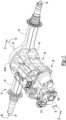
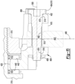
Figure 1 is a perspective view of an example of an axle assembly. -
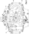
Figure 2 is a section view of the axle assembly along section line 2-2. -
Figure 3 is an end view of the axle assembly with a cover at the end of the axle assembly removed. -
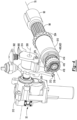
Figure 4 is a perspective view that includes an example of a shift mechanism that may be provided with the axle assembly and a first configuration of a shift collar. The latter does not show, as claimed in claim 1, that the shift collar has a second shift collar gear. -
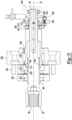
Figure 5 is a section view of a portion of the axle assembly along section line 5-5 with a second configuration of a shift collar; the second configuration of the shift collar comprises all the features of the shift collar which are mentioned in claim 1. -
Figure 6 is an exploded view of a portion of the shift mechanism and the shift collar shown inFigure 5 . -
Figure 7 is a section view of a portion of the axle assembly with the shift collar ofFigure 5 in a first position. -
Figure 8 is a section view of a portion of the axle assembly with the shift collar in a first neutral position. -
Figure 9 is a section view of a portion of the axle assembly with the shift collar in a second position. -
Figure 10 is a section view of a portion of the axle assembly with the shift collar in a second neutral position. -
Figure 11 is a section view of a portion of the axle assembly with the shift collar in a third position. -
Figure 12 is a perspective view of an example of an adjuster mechanism that may be provided with the shift mechanism. -
Figure 13 is an exploded view of the adjuster mechanism shown inFigure 12 . -
Figure 14 is a magnified view of a portion ofFigure 7 that shows the adjuster mechanism in a nominal position. -
Figure 15 illustrates an example of the adjuster mechanism in an adjusted position. - As required, detailed embodiments of the present invention are disclosed herein, whereby none of Fig-1-4 and 12-15 shows a second shift collar gear, as required by claim 1; however, it is to be understood that the disclosed embodiments are merely exemplary of the invention that may be embodied in various and alternative forms. The figures are not necessarily to scale; some features may be exaggerated or minimized to show details of particular components. Therefore, specific structural and functional details disclosed herein are not to be interpreted as limiting, but merely as a representative basis for teaching one skilled in the art to variously employ the present invention.
- Referring to
Figure 1 , an example of anaxle assembly 10 is shown. Theaxle assembly 10 may be provided with a motor vehicle like a truck, bus, farm equipment, mining equipment, military transport or weaponry vehicle, or cargo loading equipment for land, air, or marine vessels. The motor vehicle may include a trailer for transporting cargo in one or more embodiments. - The
axle assembly 10 may provide torque to one or more traction wheel assemblies that may include a tire mounted on a wheel. The wheel may be mounted to a wheel hub that may be rotatable about a wheel axis. - One or more axle assemblies may be provided with the vehicle. As is best shown with reference to
Figures 1 and2 , theaxle assembly 10 includes adrive pinion 30 and may include a housing assembly 20, adifferential assembly 22, at least oneaxle shaft 24, anelectric motor module 26, and atransmission module 28, ashift mechanism 32, or combinations thereof. - Referring to
Figure 1 , the housing assembly 20 may receive various components of theaxle assembly 10. In addition, the housing assembly 20 may facilitate mounting of theaxle assembly 10 to the vehicle. In at least one configuration, the housing assembly 20 may include anaxle housing 40 and adifferential carrier 42. - The
axle housing 40 may receive and may support theaxle shafts 24. In at least one configuration, theaxle housing 40 may include a center portion 50 and at least onearm portion 52. - The center portion 50 may be disposed proximate the center of the
axle housing 40. As is best shown inFigure 2 , the center portion 50 may define acavity 54 that may at least partially receive thedifferential assembly 22. A lower region of the center portion 50 may at least partially define asump portion 56 that may contain or collectlubricant 58.Lubricant 58 in thesump portion 56 may be splashed by aring gear 82 of thedifferential assembly 22 and distributed to lubricate various components that may or may not be received in the housing assembly 20. For instance, some splashedlubricant 58 may lubricate components that are received in thecavity 54 like thedifferential assembly 22, bearing assemblies that rotatably support thedifferential assembly 22, adrive pinion 30, and so on, while some splashedlubricant 58 may be routed out of thecavity 54 to lubricate components located outside of the housing assembly 20, such as components associated with thetransmission module 28, theshift mechanism 32, or both. - Referring to
Figure 1 , one ormore arm portions 52 may extend from the center portion 50. For instance, twoarm portions 52 may extend in opposite directions from the center portion 50 and away from thedifferential assembly 22. Thearm portions 52 may have similar configurations. For example, thearm portions 52 may each have a hollow tubular configuration that may extend around and may receive acorresponding axle shaft 24 and may help separate or isolate theaxle shaft 24 or a portion thereof from the surrounding environment. Anarm portion 52 or a portion thereof may or may not be integrally formed with the center portion 50. It is also contemplated that thearm portions 52 may be omitted. - Referring primarily to
Figure 2 , thedifferential carrier 42 may be mounted to the center portion 50 of theaxle housing 40. Thedifferential carrier 42 may support thedifferential assembly 22 and may facilitate mounting of theelectric motor module 26. For example, thedifferential carrier 42 may include one or more bearing supports that may support a bearing like a roller bearing assembly that may rotatably support thedifferential assembly 22. In at least one configuration, thedifferential carrier 42 may include a mounting flange 60 and/or abearing support wall 62. - The mounting flange 60 may facilitate mounting of the
electric motor module 26. As an example, the mounting flange 60 may be configured as a ring that may extend around theaxis 70. In at least one configuration, the mounting flange 60 may include a set of fastener holes that may be configured to receive fasteners that may secure theelectric motor module 26 to the mounting flange 60. - The
bearing support wall 62 may support bearings that may rotatably support other components of theaxle assembly 10. For example, thebearing support wall 62 may support a bearing that may rotatably support thedrive pinion 30, a bearing that may rotatably support a rotor of theelectric motor module 26, or both. Thebearing support wall 62 may extend in an axial direction away from theaxle housing 40 and may extend around theaxis 70. Thebearing support wall 62 may define a hole that may extend along or around theaxis 70 and receive thedrive pinion 30 and the bearings that rotatably support thedrive pinion 30. Thebearing support wall 62 may be integrally formed with thedifferential carrier 42 or may be a separate component that is fastened to thedifferential carrier 42. - Referring to
Figure 2 , thedifferential assembly 22 may be at least partially received in the center portion 50 of the housing assembly 20. Thedifferential assembly 22 may be rotatable about adifferential axis 80 and may transmit torque to theaxle shafts 24 and wheels. Thedifferential assembly 22 may be operatively connected to theaxle shafts 24 and may permit theaxle shafts 24 to rotate at different rotational speeds in a manner known by those skilled in the art. Thedifferential assembly 22 may have aring gear 82 that may have teeth that mate or mesh with the teeth of a gear portion of adrive pinion 30. Accordingly, thedifferential assembly 22 may receive torque from thedrive pinion 30 via thering gear 82 and transmit torque to theaxle shafts 24. - The
drive pinion 30 may operatively connect thetransmission module 28 to thedifferential assembly 22. As such, thedrive pinion 30 may transmit torque between thedifferential assembly 22 and thetransmission module 28. In at least one configuration, thedrive pinion 30 may be rotatable about theaxis 70 and may be rotatably supported inside another component, such as the bearingsupport wall 62. - Referring primarily to
Figures 2 and6 , thedrive pinion 30 may optionally include or may be coupled to adrive pinion extension 90. Thedrive pinion extension 90 may increase the axial length of thedrive pinion 30. In at least one configuration, thedrive pinion extension 90 may be a separate component from thedrive pinion 30 and may be coupled to thedrive pinion 30 such that thedrive pinion extension 90 is rotatable about theaxis 70 with thedrive pinion 30. In addition, thedrive pinion extension 90 may be fixedly positioned with respect to thedrive pinion 30 such that thedrive pinion extension 90 may not move along theaxis 70 with respect to thedrive pinion 30. It is also contemplated that thedrive pinion extension 90 may be integrally formed with thedrive pinion 30, in which case thedrive pinion 30 may be a one-piece unitary component having a greater axial length. - In at least one configuration, the
drive pinion extension 90 may extend from afirst end 92 to asecond end 94 and may include asocket 96 and thespline 98. Thesocket 96 may extend from thefirst end 92 and may receive thedrive pinion 30. Thesecond end 94 may be received inside and may be rotatably supported by asupport bearing 418. Thespline 98, if provided, may facilitate coupling of thedrive pinion extension 90 to ashift collar 310 that may be moveable along theaxis 70 as will be discussed in more detail below. - Referring to
Figure 1 , theaxle shafts 24 may transmit torque from thedifferential assembly 22 to corresponding wheel hubs and wheels. Twoaxle shafts 24 may be provided such that eachaxle shaft 24 extends through adifferent arm portion 52 ofaxle housing 40. Theaxle shafts 24 may extend along and may be rotatable about an axis, such as thedifferential axis 80. Eachaxle shaft 24 may have a first end and a second end. The first end may be operatively connected to thedifferential assembly 22. The second end may be disposed opposite the first end and may be operatively connected to a wheel. Optionally, gear reduction may be provided between anaxle shaft 24 and a wheel. - Referring to
Figure 2 , theelectric motor module 26, which may also be referred to as an electric motor, may be mounted to thedifferential carrier 42 and may be operatively connectable to thedifferential assembly 22. For instance, theelectric motor module 26 may provide torque to thedifferential assembly 22 via thetransmission module 28 and thedrive pinion 30 as will be discussed in more detail below. Theelectric motor module 26 may be primarily disposed outside thedifferential carrier 42. In addition, theelectric motor module 26 may be axially positioned between theaxle housing 40 and thetransmission module 28. In at least one configuration, theelectric motor module 26 may include amotor housing 100, acoolant jacket 102, astator 104, arotor 106, and at least onerotor bearing assembly 108. Theelectric motor module 26 may also include amotor cover 110. - The
motor housing 100 may extend between thedifferential carrier 42 and themotor cover 110. Themotor housing 100 may be mounted to thedifferential carrier 42 and themotor cover 110. For example, themotor housing 100 may extend from the mounting flange 60 of thedifferential carrier 42 to themotor cover 110. Themotor housing 100 may extend around theaxis 70 and may define amotor housing cavity 120. Themotor housing cavity 120 may be disposed inside themotor housing 100 and may have a generally cylindrical configuration. The bearingsupport wall 62 of thedifferential carrier 42 may be located inside themotor housing cavity 120. Moreover, themotor housing 100 may extend continuously around and may be spaced apart from the bearingsupport wall 62. In at least one configuration, themotor housing 100 may have an exterior side 122, an interior side 124, a first end surface 126, and asecond end surface 128. - The exterior side 122 may face away from the
axis 70 and may define an exterior or outside surface of themotor housing 100. - The interior side 124 may be disposed opposite the exterior side 122 and may face toward the
axis 70. The interior side 124 may be disposed at a substantially constant radial distance from theaxis 70 in one or more configurations. - The first end surface 126 may extend between the exterior side 122 and the interior side 124. The first end surface 126 may be disposed at an end of the
motor housing 100 that may face toward thedifferential carrier 42. For instance, the first end surface 126 may be disposed adjacent to the mounting flange 60 of thedifferential carrier 42 and may engage or contact the mounting flange 60. - The
second end surface 128 may be disposed opposite the first end surface 126. As such, thesecond end surface 128 may be disposed at an end of themotor housing 100 that may face toward themotor cover 110 and may engage or contact themotor cover 110. - The
coolant jacket 102 may help cool or remove heat from thestator 104. Thecoolant jacket 102 may be received in themotor housing cavity 120 of themotor housing 100 and may engage the interior side 124 of themotor housing 100. Thecoolant jacket 102 may extend axially (e.g., in a direction along the axis 70) between thedifferential carrier 42 and themotor cover 110. For example, thecoolant jacket 102 may extend axially from thedifferential carrier 42 to themotor cover 110. In addition, thecoolant jacket 102 may extend around theaxis 70 and around thestator 104. Accordingly, thestator 104 may be at least partially received in and may be encircled by thecoolant jacket 102. Thecoolant jacket 102 may extend in a radial direction from thestator 104 to the interior side 124 of themotor housing 100. In at least one configuration, thecoolant jacket 102 may include a plurality of channels through which coolant may flow. - The
stator 104 may be received in themotor housing cavity 120. Thestator 104 may be fixedly positioned with respect to thecoolant jacket 102. For example, thestator 104 may extend around theaxis 70 and may include stator windings that may be received inside and may be fixedly positioned with respect to thecoolant jacket 102. - The
rotor 106 may extend around and may be rotatable about theaxis 70. In addition, therotor 106 may extend around and may be supported by the bearingsupport wall 62. Therotor 106 may be received inside thestator 104, thecoolant jacket 102, and themotor housing cavity 120 of themotor housing 100. Therotor 106 may be rotatable about theaxis 70 with respect to thedifferential carrier 42 and thestator 104. In addition, therotor 106 may be spaced apart from thestator 104 but may be disposed in close proximity to thestator 104.. - One or more
rotor bearing assemblies 108 may rotatably support therotor 106. For example, arotor bearing assembly 108 may extend around and receive the bearingsupport wall 62 of thedifferential carrier 42 and may be received inside of therotor 106. Therotor 106 may be operatively connected to thedrive pinion 30. For instance, a coupling such as arotor output flange 130 may operatively connect therotor 106 to thetransmission module 28, which in turn may be operatively connectable to thedrive pinion 30. - The
motor cover 110 may be mounted to themotor housing 100 and may be disposed opposite theaxle housing 40 and thedifferential carrier 42. For example, themotor cover 110 may be mounted to thesecond end surface 128 of themotor housing 100. Themotor cover 110 may be spaced apart from and may not engage thedifferential carrier 42. Themotor cover 110 may be provided in various configurations. In at least one configuration, themotor cover 110 may include afirst side 140 and asecond side 142. Thefirst side 140 may face toward and may engage themotor housing 100. Thesecond side 142 may be disposed opposite thefirst side 140. Thesecond side 142 may face away from themotor housing 100. Themotor cover 110 may also include a motor cover opening through which thedrive pinion 30 may extend. Themotor cover 110 may be integrated with thetransmission module 28 or may be a separate component. - Referring to
Figures 2 and5 , thetransmission module 28 may transmit torque between theelectric motor module 26 and thedifferential assembly 22. As such, thetransmission module 28 may be operatively connectable to theelectric motor module 26 and thedifferential assembly 22. In at least one configuration, thetransmission module 28 may include afirst transmission housing 200, asecond transmission housing 202, and atransmission 204. Thefirst transmission housing 200 and thesecond transmission housing 202 may cooperate to define atransmission housing cavity 206 that may receive thetransmission 204. - The
first transmission housing 200 may be mounted to theelectric motor module 26. For instance, thefirst transmission housing 200 may be mounted to thesecond side 142 of themotor cover 110. As such, themotor cover 110 may separate thefirst transmission housing 200 from themotor housing 100. - The
second transmission housing 202 may be mounted to thefirst transmission housing 200. For instance, thefirst transmission housing 200 may be mounted to and may engage or contact a side of thefirst transmission housing 200 that may face away from themotor cover 110. As such, thefirst transmission housing 200 may separate thesecond transmission housing 202 from themotor cover 110. - The
transmission 204 may be operatively connected to the electric motor. In at least one configuration and as is best shown inFigure 5 , thetransmission 204 may be configured as a countershaft transmission that includes a set of drive pinion gears 210, a first countershaft gear set 212, and optionally a second countershaft gear set 214. - The set of drive pinion gears 210 may be received in the
transmission housing cavity 206 and may be arranged along theaxis 70 between thefirst transmission housing 200 and thesecond transmission housing 202. The set of drive pinion gears 210 may include a plurality of gears, some of which may be selectively coupled to thedrive pinion 30. In the configuration shown, the set of drive pinion gears 210 includes afirst gear 220, asecond gear 222, athird gear 224, and afourth gear 226; however, it is to be understood that a greater or lesser number of gears may be provided. - The
first gear 220 may extend around theaxis 70 and may be disposed proximate thefirst transmission housing 200. In at least one configuration, thefirst gear 220 may have a through hole that may receive thedrive pinion 30, an extension of thedrive pinion 30 like thedrive pinion extension 90, or both. Thefirst gear 220 may have a plurality of teeth that may be arranged around and may extend away from theaxis 70. The teeth of thefirst gear 220 may contact and may mate or mesh with teeth of a first countershaft gear that may be provided with the first countershaft gear set 212 and the second countershaft gear set 214 as will be discussed in more detail below. Thefirst gear 220 may be operatively connected to therotor 106 of theelectric motor module 26 such that therotor 106 and thefirst gear 220 are rotatable together about theaxis 70. For example, thefirst gear 220 may be fixedly positioned with respect to therotor 106 or fixedly coupled to therotor 106 such that thefirst gear 220 is not rotatable about theaxis 70 with respect to therotor 106. It is contemplated that thefirst gear 220 may be fixedly mounted to or integrally formed with therotor output flange 130. As such, thefirst gear 220 may be continuously connected to therotor 106 such that thefirst gear 220 and therotor 106 may be rotatable together about theaxis 70 but may not be rotatable with respect to each other. It is also contemplated that thefirst gear 220 may be selectively coupled to thedrive pinion 30 or drivepinion extension 90, such as with a shift collar. In addition, thefirst gear 220 may be decoupled from thedrive pinion 30 and may be rotatable with respect to thedrive pinion 30. As such, a clutch orshift collar 310 may not connect thefirst gear 220 to thedrive pinion 30 or thedrive pinion extension 90. Thedrive pinion extension 90, if provided, may be received inside thefirst gear 220 and may be spaced apart from thefirst gear 220. In at least one configuration, thefirst gear 220 may be axially positioned along theaxis 70 between thesecond gear 222 and theelectric motor module 26. - Referring to
Figures 5 and7 , thesecond gear 222 may extend around theaxis 70. In at least one configuration, thesecond gear 222 may have a through hole that may receive thedrive pinion 30, thedrive pinion extension 90, or both. Thesecond gear 222 may have a plurality of teeth that may be arranged around and may extend away from theaxis 70. The teeth of thesecond gear 222 may contact and may mate or mesh with teeth of a second countershaft gear that may be provided with the first countershaft gear set 212 and the second countershaft gear set 214 as will be discussed in more detail below. As is best shown inFigure 7 , thesecond gear 222 may also haveinner gear teeth 232 that may extend toward theaxis 70 and may be received in the through hole. Thesecond gear 222 may have a different diameter than thefirst gear 220. For example, thesecond gear 222 may have a larger diameter than thefirst gear 220 as is best shown inFigure 5 . In at least one configuration, thesecond gear 222 may be axially positioned along theaxis 70 between thefirst gear 220 and thethird gear 224. Thedrive pinion 30 or drivepinion extension 90, if provided, may be received inside thesecond gear 222 and may be spaced apart from thesecond gear 222 in one or more configurations. - Referring to
Figures 5 and7 , thethird gear 224 may extend around theaxis 70. In at least one configuration, thethird gear 224 may have a through hole that may receive thedrive pinion 30, thedrive pinion extension 90, or both. Thethird gear 224 may have a plurality of teeth that may be arranged around and may extend away from theaxis 70. The teeth of thethird gear 224 may contact and may mate or mesh with teeth of a third countershaft gear that may be provided with the first countershaft gear set 212 and the second countershaft gear set 214 as will be discussed in more detail below. As is best shown inFigure 7 , thethird gear 224 may also haveinner gear teeth 234 that may extend toward theaxis 70 and may be received in the through hole. Thethird gear 224 may have a different diameter than thefirst gear 220 and thesecond gear 222. For example, thethird gear 224 may have a larger diameter than thefirst gear 220 and thesecond gear 222 as is best shown inFigure 5 . In at least one configuration, thethird gear 224 be axially positioned along theaxis 70 between thesecond gear 222 and thefourth gear 226. Thedrive pinion 30 or drivepinion extension 90, if provided, may be received inside thethird gear 224 and may be spaced apart from thethird gear 224 in one or more configurations. - Referring to
Figures 5 and7 , thefourth gear 226 may extend around theaxis 70. In at least one configuration, thefourth gear 226 may have a through hole that may receive thedrive pinion 30, thedrive pinion extension 90, or both. Thefourth gear 226 may have a plurality of teeth that may be arranged around and may extend away from theaxis 70. The teeth of thefourth gear 226 may contact and may mate or mesh with teeth of a fourth countershaft gear that may be provided with the first countershaft gear set 212 and the second countershaft gear set 214 as will be discussed in more detail below. As is best shown inFigure 7 , thefourth gear 226 may also haveinner gear teeth 236 that may extend toward theaxis 70 and may be received in the through hole. Thefourth gear 226 may have a different diameter than thefirst gear 220, thesecond gear 222, and thethird gear 224, such as a larger diameter. In at least one configuration, thefourth gear 226 be axially positioned along theaxis 70 further from theelectric motor module 26 than thefirst gear 220, thesecond gear 222, and thethird gear 224. As such, thefourth gear 226 may be axially positioned proximate or adjacent to a side of thesecond transmission housing 202 that is disposed opposite thefirst transmission housing 200. Thedrive pinion 30 or drivepinion extension 90 may be received inside thefourth gear 226 and may be spaced apart from thefourth gear 226 in one or more configurations. - Referring to
Figure 5 , thrustbearings 240 may optionally be provided between members of the set of drive pinion gears 210, between thefirst transmission housing 200 and the set of drive pinion gears 210, between thesecond transmission housing 202 and the set of drive pinion gears 210, or combinations thereof. For instance, a first thrust bearing 240 may be axially positioned between thefirst transmission housing 200 and thefirst gear 220, a second thrust bearing 240 may be axially positioned between thefirst gear 220 and thesecond gear 222, a third thrust bearing 240 may be axially positioned between thesecond gear 222 and thethird gear 224, a fourth thrust bearing 240 may be axially positioned between thethird gear 224 and thefourth gear 226, and a fifth thrust bearing 240 may be axially positioned between thefourth gear 226 and thesecond transmission housing 202. - The first countershaft gear set 212 may be received in the
transmission housing cavity 206 and is in meshing engagement with the set of drive pinion gears 210. The first countershaft gear set 212 is rotatable about afirst countershaft axis 250. Thefirst countershaft axis 250 may be disposed parallel or substantially parallel to theaxis 70 in one or more embodiments. The first countershaft gear set 212 may include afirst countershaft 260 and a plurality of gears. In the configuration shown, the plurality of gears of the first countershaft gear set 212 include afirst countershaft gear 270, asecond countershaft gear 272, athird countershaft gear 274, and afourth countershaft gear 276; however, it is contemplated that a greater number of countershaft gears or a lesser number of countershaft gears may be provided. - The
first countershaft 260 may be rotatable about thefirst countershaft axis 250. For instance, thefirst countershaft 260 may be rotatably supported on thefirst transmission housing 200 and thesecond transmission housing 202 by corresponding bearingassemblies 280. For example, first andsecond bearing assemblies 280 may be located near opposing first and second ends thefirst countershaft 260, respectively. Thefirst countershaft 260 may support and be rotatable with thefirst countershaft gear 270, thesecond countershaft gear 272, thethird countershaft gear 274, and thefourth countershaft gear 276. - The
first countershaft gear 270 may be fixedly disposed on thefirst countershaft 260 or fixedly mounted to thefirst countershaft 260. As such, thefirst countershaft gear 270 may rotate about thefirst countershaft axis 250 with thefirst countershaft 260 and may not be rotatable with respect to thefirst countershaft 260. For example, thefirst countershaft gear 270 may have a hole that may receive thefirst countershaft 260 and may be fixedly coupled to thefirst countershaft 260. Thefirst countershaft gear 270 may extend around thefirst countershaft axis 250 and may have a plurality of teeth that may be arranged around and may extend away from thefirst countershaft axis 250. The teeth of thefirst countershaft gear 270 may contact and may mate or mesh with the teeth of thefirst gear 220. In at least one configuration, thefirst countershaft gear 270 may be axially positioned along thefirst countershaft axis 250 between thefirst transmission housing 200 and thesecond countershaft gear 272 of the first countershaft gear set 212. - The
second countershaft gear 272 may be fixedly disposed on thefirst countershaft 260 or fixedly mounted to thefirst countershaft 260. As such, thesecond countershaft gear 272 may rotate about thefirst countershaft axis 250 with thefirst countershaft 260 and may not be rotatable with respect to thefirst countershaft 260. For example, thesecond countershaft gear 272 may have a hole that may receive thefirst countershaft 260 and may be fixedly coupled to thefirst countershaft 260. Thesecond countershaft gear 272 may extend around thefirst countershaft axis 250 and may have a plurality of teeth that may be arranged around and may extend away from thefirst countershaft axis 250. The teeth of thesecond countershaft gear 272 may contact and may mate or mesh with the teeth of thesecond gear 222. Thesecond countershaft gear 272 may have a different diameter than thefirst countershaft gear 270 and thethird countershaft gear 274. In at least one configuration, thesecond countershaft gear 272 may be axially positioned along thefirst countershaft axis 250 between thefirst countershaft gear 270 of the first countershaft gear set 212 and thethird countershaft gear 274 of the first countershaft gear set 212. - The
third countershaft gear 274 may be fixedly disposed on thefirst countershaft 260 or fixedly mounted to thefirst countershaft 260. As such, thethird countershaft gear 274 may rotate about thefirst countershaft axis 250 with thefirst countershaft 260 and may not be rotatable with respect to thefirst countershaft 260. For example, thethird countershaft gear 274 may have a hole that may receive thefirst countershaft 260 and may be fixedly coupled to thefirst countershaft 260. Thethird countershaft gear 274 may extend around thefirst countershaft axis 250 and may have a plurality of teeth that may be arranged around and may extend away from thefirst countershaft axis 250. The teeth of thethird countershaft gear 274 may contact and may mate or mesh with the teeth of thethird gear 224. Thethird countershaft gear 274 may have a different diameter than thefirst countershaft gear 270 and thesecond countershaft gear 272. In at least one configuration, thethird countershaft gear 274 may be axially positioned along thefirst countershaft axis 250 between thesecond countershaft gear 272 of the first countershaft gear set 212 and thefourth countershaft gear 276 of the first countershaft gear set 212. - The
fourth countershaft gear 276 may be fixedly disposed on thefirst countershaft 260 or fixedly mounted to thefirst countershaft 260. As such, thefourth countershaft gear 276 may rotate about thefirst countershaft axis 250 with thefirst countershaft 260 and may not be rotatable with respect to thefirst countershaft 260. For example, thefourth countershaft gear 276 may have a hole that may receive thefirst countershaft 260 and may be fixedly coupled to thefirst countershaft 260 or may be integrally formed with thefirst countershaft 260. Thefourth countershaft gear 276 may extend around thefirst countershaft axis 250 and may have a plurality of teeth that may be arranged around and may extend away from thefirst countershaft axis 250. The teeth of thefourth countershaft gear 276 may contact and may mate or mesh with the teeth of thefourth gear 226. Thefourth countershaft gear 276 may have a different diameter than thefirst countershaft gear 270, thesecond countershaft gear 272, and thethird countershaft gear 274. In at least one configuration, thefourth countershaft gear 276 may be axially positioned along thefirst countershaft axis 250 further from theelectric motor module 26 than thethird countershaft gear 274 of the first countershaft gear set 212. - The second countershaft gear set 214, if provided, may be received in the
transmission housing cavity 206 and may be rotatable about a second countershaft axis 250'. The second countershaft axis 250' may be disposed parallel or substantially parallel to theaxis 70 and thefirst countershaft axis 250 in one or more embodiments. The second countershaft gear set 214 may generally be disposed on an opposite side of theaxis 70 from the first countershaft gear set 212 or may be disposed such that thefirst countershaft axis 250 and the second countershaft axis 250' may be disposed at a common radial distance from theaxis 70. The first and second countershaft gear sets 212, 214 may be positioned at any suitable rotational angle or position about theaxis 70. - The second countershaft gear set 214 may have the same or substantially the same configuration as the first countershaft gear set 212. For example, the second countershaft gear set 214 may include a second countershaft 260' that may be analogous to or may have the same structure as the
first countershaft 260. In addition, the second countershaft gear set 214 may include a plurality of gears that are rotatable with the second countershaft 260'. In the configuration shown, the plurality of gears of the second countershaft gear set 214 include a first countershaft gear 270', a second countershaft gear 272', a third countershaft gear 274', and a fourth countershaft gear 276'; however, it is contemplated that a greater number of gears or a lesser number of gears may be provided. The first countershaft gear 270', second countershaft gear 272', third countershaft gear 274', and the fourth countershaft gear 276' of the second countershaft gear set 214 may be analogous to or may have the same structure as thefirst countershaft gear 270,second countershaft gear 272,third countershaft gear 274, and thefourth countershaft gear 276, respectively, of the first countershaft gear set 212. The first countershaft gear 270', second countershaft gear 272', third countershaft gear 274', and the fourth countershaft gear 276' may be arranged along and may be rotatable about a second countershaft axis 250' rather than thefirst countershaft axis 250 and may be fixed to the second countershaft 260' rather than thefirst countershaft 260. - The
first gear 220 and the first countershaft gears 270, 270' may provide a different gear ratio than thesecond gear 222 and the second countershaft gears 272, 272', thethird gear 224 and the third countershaft gears 274, 274', and thefourth gear 226 and the fourth countershaft gears 276, 276'. Gear ratios may be provided that are greater than 1:1, less than 1:1, equal (i.e., 1:1), or combinations thereof. - The teeth of the drive pinion gears and the countershaft gears may be of any suitable type. As a non-limiting example, the meshing teeth of the members of the set of drive pinion gears 210, the gears of the first countershaft gear set 212, and the gears of the second countershaft gear set 214 may have a helical configuration.
- Referring primarily to
Figures 2-4 , theshift mechanism 32 may selectively connect thetransmission module 28 and thedrive pinion 30. For example, theshift mechanism 32 may operatively connect a member of the set of drive pinion gears 210 to thedrive pinion 30 to provide torque at a desired gear ratio, and hence may change the torque transmitted between theelectric motor module 26 and thedifferential assembly 22. Theshift mechanism 32 may couple one member of the set of drive pinion gears 210 at a time to thedrive pinion 30. The member of the set of drive pinion gears 210 that is coupled to thedrive pinion 30 may be rotatable about theaxis 70 with thedrive pinion 30. - The
shift mechanism 32 may be received in or partially received in a shiftmechanism housing cavity 300, which is best shown inFigures 2 and3 . The shiftmechanism housing cavity 300 may be partially defined by thesecond transmission housing 202 and may be disposed proximate an end of theaxle assembly 10. Referring toFigures 1 and2 , acover 302 may be mounted on the end of thesecond transmission housing 202 to help enclose the shiftmechanism housing cavity 300. Thecover 302 is removed inFigure 3 . - The
shift mechanism 32 may have any suitable configuration. In at least one configuration such as is shown inFigures 4 and6 , theshift mechanism 32 may include ashift collar 310, anactuator 312, adetent linkage 314, alinkage 316, and anadjuster mechanism 318. - The
shift collar 310 is rotatable about theaxis 70 with thedrive pinion 30. In addition, theshift collar 310 is moveable along theaxis 70 with respect to thedrive pinion 30. Theshift collar 310 selectively connects a member of the set of drive pinion gears 210 to thedrive pinion 30 as will be discussed in more detail below. Theshift collar 310 may be at least partially received in the shiftmechanism housing cavity 300 and may be extendable through components of thetransmission 204, such as the set of drive pinion gears 210. In at least one configuration, theshift collar 310 may include afirst end 320, asecond end 322, ashift collar hole 324, and ashift collar spline 326. Theshift collar 310 includes a firstshift collar gear 334 and a secondshift collar gear 336 and may also include a first tubularshift collar portion 330, a second tubularshift collar portion 332, a firstshift collar gear 334, a secondshift collar gear 336, a threadedportion 338 or combinations thereof. - The
first end 320 may face toward thedrive pinion 30. In addition, thefirst end 320 may be disposed adjacent to thedrive pinion 30 or thedrive pinion extension 90. - The
second end 322 may be disposed opposite thefirst end 320. As such, thesecond end 322 may face away from thedrive pinion 30. - The
shift collar hole 324 may extend along theaxis 70 between thefirst end 320 and thesecond end 322. In at least one configuration, theshift collar hole 324 may be configured as a through hole that may extend from thefirst end 320 to thesecond end 322. Thedrive pinion 30 or thedrive pinion extension 90 may be received inside theshift collar hole 324. - The
shift collar spline 326 may couple theshift collar 310 to thedrive pinion 30 or thedrive pinion extension 90. Theshift collar spline 326 may be disposed in theshift collar hole 324 and may be axially positioned near thefirst end 320. Theshift collar spline 326 may extend toward theaxis 70 and may mate with a spline of thedrive pinion 30 or thespline 98 of thedrive pinion extension 90 that may have spline teeth that may extend away from theaxis 70. The mating splines may allow theshift collar 310 to move in an axial direction or along theaxis 70 while inhibiting rotation of theshift collar 310 about theaxis 70 with respect to thedrive pinion 30. Thus, theshift collar 310 may be rotatable about theaxis 70 with thedrive pinion 30 when theshift collar spline 326 mates with the spline of thedrive pinion 30 or thedrive pinion extension 90. - The first tubular
shift collar portion 330 may extend from thefirst end 320 toward thesecond end 322. The first tubularshift collar portion 330 may have a hollow tubular configuration and may be at least partially received inside the set of drive pinion gears 210 of thetransmission 204. The first tubularshift collar portion 330 may have a larger outside diameter than the second tubularshift collar portion 332. - The second tubular
shift collar portion 332, if provided, may extend from thesecond end 322 toward the first tubularshift collar portion 330 or to the first tubularshift collar portion 330. For instance, the second tubularshift collar portion 332 may have a hollow tubular configuration and may be at least partially disposed outside of the set of drive pinion gears 210. - The first
shift collar gear 334 may be disposed between thefirst end 320 and thesecond end 322 of theshift collar 310. In at least one configuration, the firstshift collar gear 334 may be disposed opposite theshift collar hole 324 and may extend from the first tubularshift collar portion 330. The firstshift collar gear 334 may have teeth that may be arranged around theaxis 70 and that may extend away from theaxis 70 and away from theshift collar hole 324. Theshift collar spline 326 may be disposed opposite the firstshift collar gear 334. It is noted that an example of ashift collar 310 that has a firstshift collar gear 334 but not a secondshift collar gear 336 is shown inFigures 2 and4 while an example of ashift collar 310 that has a firstshift collar gear 334 and a secondshift collar gear 336 is shown inFigures 5-11 . - Referring to
Figure 6 , the second shift collar gear 336is spaced apart from the firstshift collar gear 334. The secondshift collar gear 336 may be axially positioned between thefirst end 320 and thesecond end 322. For instance, the secondshift collar gear 336 may be axially positioned between the firstshift collar gear 334 and the second tubularshift collar portion 332. In at least one configuration, the secondshift collar gear 336 may be disposed opposite theshift collar hole 324 and may extend from the first tubularshift collar portion 330. The secondshift collar gear 336 may have teeth that may be arranged around theaxis 70 and that may extend away from theaxis 70 and away from theshift collar hole 324. The secondshift collar gear 336 may have a similar configuration as the firstshift collar gear 334 or a different configuration. For instance, the teeth of the secondshift collar gear 336 may have a greater axial length than the teeth of the firstshift collar gear 334 to increase torque transmission capacity, reduce shift execution time, or both as will be discussed in more detail below. Theshift collar spline 326 may not be disposed opposite the secondshift collar gear 336 in one or more embodiments. - The threaded
portion 338 may be axially positioned between thefirst end 320 and thesecond end 322. For instance, the threadedportion 338 may be provided with the second tubularshift collar portion 332 and may be axially positioned between the first tubularshift collar portion 330 and thesecond end 322. The threadedportion 338 may be disposed on an exterior side of the second tubularshift collar portion 332 that may face away from theaxis 70. It is also contemplated that the threadedportion 338 may be omitted. - Referring to
Figures 3 and4 , theactuator 312 may be configured to move theshift collar 310 along theaxis 70 to selectively connect a member of the set of drive pinion gears 210 to thedrive pinion 30. Theactuator 312 may be of any suitable type, such as an electrical, electromechanical, or mechanical actuator. In at least one configuration, theactuator 312 may be mounted to thesecond transmission housing 202. A portion of theactuator 312 may be rotatable about anactuator axis 350. For instance, theactuator 312 may have an actuator shaft that may extend along theactuator axis 350 and may be rotatable about theactuator axis 350. The actuator shaft may be operatively connected to thedetent linkage 314. - Referring to
Figure 4 , thedetent linkage 314 may be fixedly coupled to theactuator 312. For instance, thedetent linkage 314 may be coupled to the actuator shaft and may be rotatable about theactuator axis 350 with the actuator shaft. Thedetent linkage 314 may define a plurality ofrecesses 360. Therecesses 360 may be configured to receive adetent feature 362. Thedetent feature 362 may inhibit rotation of thedetent linkage 314 about theactuator axis 350 when thedetent feature 362 is received in arecess 360. For example, rotation of thedetent linkage 314 may be inhibited when thedetent feature 362 is in arecess 360 and a sufficient actuation force is not provided by theactuator 312 to overcome the rotational resistance exerted by thedetent feature 362. Thedetent linkage 314 may also be fixedly positioned with respect to thelinkage 316. As such, thedetent feature 362 may inhibit movement of thelinkage 316. - The
linkage 316 may operatively connect theactuator 312 to theshift collar 310 and theadjuster mechanism 318. In at least one configuration, thelinkage 316 may be positioned along theactuator axis 350 closer to theactuator 312 than thedetent linkage 314 is positioned to theactuator 312. Thelinkage 316 may be coupled to theactuator 312 and thedetent linkage 314 such that thelinkage 316 may be rotatable about theactuator axis 350 with the actuator shaft and thedetent linkage 314. For example, thelinkage 316 may be coupled to thedetent linkage 314 with one ormore fasteners 370, such as pins or bolts. It is also contemplated that thedetent linkage 314 and thelinkage 316 may be integrally formed. In at least one configuration, thelinkage 316 may include anopening 372 that may facilitate coupling of thelinkage 316 to theadjuster mechanism 318. - Referring to
Figures 6 ,12 and13 , theadjuster mechanism 318 may connect thelinkage 316 to theshift collar 310. In addition, theadjuster mechanism 318 may allow the axial position of theshift collar 310 to be adjusted independent of operation of theactuator 312 or without rotating the components of theshift mechanism 32 like the actuator shaft,detent linkage 314, andlinkage 316 about theactuator axis 350. In at least one configuration, theadjuster mechanism 318 may include acollar assembly 400, afollower 402, and anadjustment screw 404. Theadjuster mechanism 318 may also include a lockingscrew 406 and aretainer 408. As is best shown inFigure 6 , afirst thrust bearing 410, a second thrust bearing 412, aretainer nut 414, or combinations thereof may optionally be associated with or disposed adjacent to theadjuster mechanism 318. It is also contemplated that theadjuster mechanism 318 may be omitted or reconfigured to omit components such as theadjustment screw 404, lockingscrew 406, andretainer 408. For instance, thecollar assembly 400 may be provided with acollar 420 and ashift block 422 that may be separate components that may be fastened together such that spacers or shims may be provided between thecollar 420 and shift block 422 to adjust the axial positioning of theshift collar 310. It is also contemplated that theadjuster mechanism 318 may be provided with other configurations, such as when a shift fork is used to operatively connect a shift collar to an actuator. - The
collar assembly 400 may receive theshift collar 310. In at least one configuration, thecollar assembly 400 may include acollar 420 and ashift block 422. - The
collar 420 may extend at least partially around theaxis 70 in theshift collar 310. For instance, thecollar 420 may be configured as a ring that may extend around theaxis 70. In at least one configuration, thecollar 420 may include afirst collar side 440, asecond collar side 442, and acollar hole 444. - The
first collar side 440 may face toward thetransmission module 28, thedrive pinion 30, or both. - The
second collar side 442 may be disposed opposite thefirst collar side 440. As such, thesecond collar side 442 may face away from thetransmission module 28, thedrive pinion 30, or both. - The
collar hole 444 may extend between thefirst collar side 440 and thesecond collar side 442. Thecollar hole 444 may be a through hole that may extend through thecollar 420. Theshift collar 310 may be received inside thecollar hole 444 and may be rotatable about theaxis 70 with respect to thecollar 420. For instance, the second tubularshift collar portion 332 may be received inside thecollar hole 444 and may extend through thecollar hole 444. In at least one configuration, thecollar hole 444 may receive a bearing assembly that may be positioned between theshift collar 310 and thecollar 420. For example, the bearing assembly may extend from an outside circumference of the second tubularshift collar portion 332 to the inside diameter of thecollar 420 that defines thecollar hole 444. - The
shift block 422 may be fixedly positioned with respect to thecollar 420. Theshift block 422 may be integrally formed with thecollar 420 or may be provided as a separate component that is attached to thecollar 420. For instance, theshift block 422 may extend from an outside circumference of thecollar 420, thesecond collar side 442, or combinations thereof. In at least one configuration and as is best shown inFigures 12 and13 , theshift block 422 may define anelongated slot 470 and afirst hole 472. Theshift block 422 may also define asecond hole 474, at least one lockingscrew hole 476, or combinations thereof. - The
elongated slot 470 may be open in at least a direction that extends away from theaxis 70. Theelongated slot 470 may receive thefollower 402 with a clearance fit and may be configured to allow thecollar assembly 400 to move in an axial direction or along theaxis 70 with respect to thefollower 402. Theelongated slot 470 may be longer in a direction that may extend parallel to theaxis 70. In at least one configuration, theelongated slot 470 may have amajor axis 480 and aminor axis 482. - The
major axis 480 may extend parallel or substantially parallel to theaxis 70. For instance, themajor axis 480 may extend from thefirst hole 472 toward or to thesecond hole 474. Themajor axis 480 may have a greater length than theminor axis 482. As such, theelongated slot 470 may extend a greater distance along themajor axis 480 than along theminor axis 482. - The
minor axis 482 may be disposed substantially perpendicular to themajor axis 480. For instance, theminor axis 482 may extend in a substantially vertical direction from the perspective shown. - The
first hole 472 may extend from theelongated slot 470. In at least one configuration, thefirst hole 472 may be a through hole that may extend through the shift block 422 from theelongated slot 470 to an exterior surface of theshift block 422. In at least one configuration, thefirst hole 472 may not be threaded and may extend substantially parallel to themajor axis 480 of theelongated slot 470 and may be coaxially disposed with themajor axis 480 of theelongated slot 470. - The
second hole 474, if provided, may be coaxially disposed with thefirst hole 472. In the configuration shown, thesecond hole 474 is disposed closer to theshift collar 310 than thefirst hole 472; however, it is contemplated that the positioning of thefirst hole 472 and thesecond hole 474 may be reversed. Thesecond hole 474 may extend from theelongated slot 470. In at least one configuration, thesecond hole 474 may be a through hole that may extend through the shift block 422 from theelongated slot 470 to an exterior surface of theshift block 422 that may be disposed opposite thefirst hole 472. In at least one configuration, thesecond hole 474 may not be threaded and may be coaxially disposed with thefirst hole 472. Thesecond hole 474 may extend substantially parallel to themajor axis 480 of theelongated slot 470 and may be coaxially disposed with themajor axis 480 of theelongated slot 470. In at least one configuration, thesecond hole 474 may have a smaller diameter than thefirst hole 472. Alternatively, thesecond hole 474 may have the same diameter or a larger diameter than thefirst hole 472. - One or more
locking screw holes 476 may be spaced apart from thefirst hole 472, thesecond hole 474, or both. In the configuration shown, the lockingscrew hole 476 is disposed proximate thefirst hole 472 and is spaced apart from thefirst hole 472. The lockingscrew hole 476 may receive the lockingscrew 406. In at least one configuration, the lockingscrew hole 476 may be a blind hole, a threaded hole, or both. - The
follower 402 may connect or couple thelinkage 316 to thecollar assembly 400. As such, thefollower 402 may help operatively connect theactuator 312 to thecollar assembly 400. In at least one embodiment, thefollower 402 may be configured as a generally cylindrical pin that may extend along afollower axis 490. Thefollower axis 490 may be disposed substantially perpendicular to theaxis 70 and substantially perpendicular to themajor axis 480 of theelongated slot 470. A portion of thefollower 402 may be received in theopening 372 of thelinkage 316 and another portion of thefollower 402 may be received in theelongated slot 470. Thefollower 402 may be sized to fit within theelongated slot 470 such that thefollower 402 may be moveable in theelongated slot 470 along themajor axis 480. For instance, thefollower 402 may have a width or diameter that may be less than the length of themajor axis 480 of theelongated slot 470, theminor axis 482 of theelongated slot 470, or both. In at least one configuration, thefollower 402 may define a threadedhole 492. The threadedhole 492 may be received in theelongated slot 470 and may be configured to receive theadjustment screw 404. - The
adjustment screw 404 may couple thecollar assembly 400 to thefollower 402. For instance, theadjustment screw 404 may be received in thefirst hole 472 of theshift block 422 and the threadedhole 492 of thefollower 402. Theadjustment screw 404 may also be receivable in thesecond hole 474 of theshift block 422 if asecond hole 474 is provided. Theadjustment screw 404 may be rotatable about anadjustment screw axis 500, which may be disposed substantially parallel to and may be coaxial with themajor axis 480 of theelongated slot 470. In at least one configuration and as is best shown inFigure 13 , theadjustment screw 404 may include ahead 510, a threadedportion 512, afirst shank portion 514, asecond shank portion 516, or combinations thereof. - The
head 510 may be disposed proximate an end of theadjustment screw 404. For instance, thehead 510 may be disposed adjacent to thefirst hole 472 of theshift block 422 and may be disposed outside of thefirst hole 472. Thehead 510 may extend away from theaxis 70 and may protrude from thefirst shank portion 514. In at least one configuration, thehead 510 may include a plurality ofteeth 520. Theteeth 520 may be arranged around theadjustment screw axis 500 and may extend away from theadjustment screw axis 500. A recess orgap 522 may be provided betweenadjacent teeth 520. For clarity, only some of the gaps are labeled inFigure 13 . - The threaded
portion 512 may be positioned along theadjustment screw axis 500 between thehead 510 and a distal end of theadjustment screw 404. The threadedportion 512 may be received in theelongated slot 470. The threadedportion 512 may also be received in the threadedhole 492 in thefollower 402. - The
first shank portion 514 may extend between thehead 510 and the threadedportion 512. Thefirst shank portion 514 may be received in thefirst hole 472 of theshift block 422. Thefirst shank portion 514 may be rotatable in thefirst hole 472 and may or may not be threaded. - The
second shank portion 516, if provided, may extend between the threadedportion 512 and the distal end of theadjustment screw 404 that is disposed opposite thehead 510. Thesecond shank portion 516 may be received in thesecond hole 474 of theshift block 422. Thesecond shank portion 516 may be rotatable in thesecond hole 474. In at least one configuration, thesecond shank portion 516 may protrude out of thesecond hole 474 and may include a groove orindentation 530 that may receive theretainer 408. Optionally, thesecond shank portion 516 may have a different diameter than thefirst shank portion 514, such as a smaller diameter, and may be threaded or unthreaded. It is also contemplated that thesecond shank portion 516 may be omitted, such as when thesecond hole 474 is not provided. - The locking
screw 406 may inhibit rotation of theadjustment screw 404. For instance, the lockingscrew 406 may be partially received in the lockingscrew hole 476 of theshift block 422. A portion of the lockingscrew 406 that protrudes from and may not be received in the lockingscrew hole 476 may engage theadjustment screw 404. For example, the head of the lockingscrew 406 may engage thehead 510 of theadjustment screw 404 and may be received in agap 522 betweenadjacent teeth 520 of thehead 510. As such, the lockingscrew 406 may engage theteeth 520 that are disposed adjacent to thegap 522 in which the lockingscrew 406 is received, thereby inhibiting rotation of theadjustment screw 404. - The
retainer 408 may limit axial movement of theadjustment screw 404 along theadjustment screw axis 500. Theretainer 408 may inhibit removal of theadjustment screw 404 from theshift block 422. Theretainer 408 may have any suitable configuration. For example, theretainer 408 may be configured as a fastener such as a snap ring, such screw, retaining pin, washer, or the like. In at least one configuration, theretainer 408 may be mounted to thesecond shank portion 516 proximate the distal end of theadjustment screw 404. For instance, theretainer 408 may be received in theindentation 530 in thesecond shank portion 516 and may be disposed outside of thesecond hole 474. - Referring to
Figure 6 , the first thrust bearing 410 may facilitate rotation of theshift collar 310 about theaxis 70 with respect to thecollar assembly 400. The first thrust bearing 410 may be axially positioned between thefirst collar side 440 and theshift collar 310. Optionally, washers may be axially positioned adjacent to one or both sides of thefirst thrust bearing 410. - The second thrust bearing 412 may facilitate rotation of the
shift collar 310 about theaxis 70 with respect to thecollar assembly 400. The second thrust bearing 412 may be positioned between thesecond collar side 442 and theretainer nut 414. Optionally a washer may be axially positioned adjacent to one or both sides of thefirst thrust bearing 410. For example, a washer may be provided between the second thrust bearing 412 and theretainer nut 414. - The
retainer nut 414 may be mounted to theshift collar 310. For instance, theretainer nut 414 may have a threaded hole that may receive the second tubularshift collar portion 332 and mate with the threadedportion 338 of theshift collar 310. Theretainer nut 414 may inhibit axial movement of theshift collar 310 with respect to thecollar 420 and may help secure thefirst thrust bearing 410 and the second thrust bearing 412. It is also contemplated that theretainer nut 414 may be omitted and a different fastener or fastening technique may be used. For instance, a fastener like a snap ring or a press-fit fastener may replace a threaded connection. - An
encoder disc 416 may optionally be mounted to thedrive pinion 30 or thedrive pinion extension 90. In at least one configuration, theencoder disc 416 may be disposed adjacent to theretainer nut 414. For instance, theencoder disc 416 may be axially positioned between theretainer nut 414 and a support bearing 418 that rotatably supports thedrive pinion 30 or drivepinion extension 90. For example, the support bearing 418 may be positioned between a shoulder of thedrive pinion 30 or drivepinion extension 90 and the support bearing 418, if provided. Theencoder disc 416 may have detectable features such as protrusions and/or recesses that may be detectable by a sensor to detect rotation or the rotational speed of thedrive pinion 30. - The
support bearing 418 may rotatably support thedrive pinion 30 or drivepinion extension 90. For instance, thedrive pinion 30 or drivepinion extension 90 may be received inside and may be rotatably supported by the support bearing 418, which in turn may be supported by thesecond transmission housing 202, thecover 302, or both. - The
adjuster mechanism 318 may allow theshift collar 310 and thecollar assembly 400 to be moved along theaxis 70 to more precisely position theshift collar 310 with respect to the set of drive pinion gears 210 and their inner gear teeth. As such, theadjuster mechanism 318 may compensate for design tolerances, such as design tolerances that may be associated with the axial positioning of the drive pinion gears 210, thedetent linkage 314,linkage 316, shimming of thethrust bearings 240, or combinations thereof. Axial alignment of the gear portion or gear portions of theshift collar 310 and the inner gear teeth of the set of drive pinion gears 210 may be adjusted, which may improve gear engagement and shifting accuracy when theshift collar 310 is shifted with theactuator 312. Proper axial adjustment may inhibit collar kick-out or help ensure that teeth of a gear portion or gear portions of theshift collar 310 remain engaged with a drive pinion gear and may help reduce tooth flank wear, including when teeth flanks have crowned profiles (e.g., mating concave and convex flanks). An example of how theadjuster mechanism 318 may be operated is as follows. - First, the
detent feature 362, which is best shown inFigure 4 , may lock thedetent linkage 314 so that thedetent linkage 314 may be inhibited from rotating about theactuator axis 350 and so that thelinkage 316 is held in a stationary position. Thelinkage 316 may then inhibit movement of thefollower 402. - Next, the locking
screw 406 may be disengaged from theadjustment screw 404. For instance, the lockingscrew 406 may be rotated to disengage the lockingscrew 406 from thehead 510 of theadjustment screw 404. - Next, the
adjustment screw 404 may be rotated about theadjustment screw axis 500. Rotating theadjustment screw 404 may cause thecollar assembly 400 and theshift collar 310 to move along theaxis 70 with respect to thefollower 402. An example of such movement is shown by comparingFigure 14 withFigure 15 . InFigure 14 , thecollar assembly 400 is shown in a nominal position in which thefollower 402 is generally centered in theelongated slot 470. Rotating theadjustment screw 404 in a first direction about theadjustment screw axis 500 may loosen theadjustment screw 404 with respect to thefollower 402, thereby actuating thecollar assembly 400 and theshift collar 310 along theaxis 70 toward thecover 302, or to the right from the perspective shown and to or toward the position shown inFigure 15 . Conversely, rotating theadjustment screw 404 in a second direction about theadjustment screw axis 500 that is opposite the first direction may tighten theadjustment screw 404 and actuate thecollar assembly 400 and theshift collar 310 along theaxis 70 away from thecover 302. Theadjustment screw 404 may be rotated to axially align the firstshift collar gear 334 or secondshift collar gear 336 with a member of the set of drive pinion gears 210. - Finally, the locking
screw 406 may be tightened to engage theadjustment screw 404. For instance, the lockingscrew 406 may be received in thegap 522 in thehead 510 of theadjustment screw 404 to inhibit rotation of theadjustment screw 404 about theadjustment screw axis 500 as previously discussed. Theactuator 312 may then be subsequently used to move theshift collar 310 along the axis while theadjuster mechanism 318 may remain fixed and moves axially with thecollar assembly 400. - It is also contemplated that the
adjuster mechanism 318 may be provided to adjust the axial position of a shift collar that is provided with an axle assembly having any suitable configuration. For instance, theadjuster mechanism 318 may be provided with an axle assembly that does not have anelectric motor module 26 or that has a transmission module with a different configuration, such as a planetary gear configuration. - Referring to
Figures 7-11 , theactuator 312 may move theshift collar 310 along theaxis 70 between a plurality of positions to selectively couple theshift collar 310 to thetransmission 204 or to decouple theshift collar 310 from thetransmission 204. For instance, theactuator 312 may move theshift collar 310 along theaxis 70 between the first, second, and third positions. Examples of these positions are illustrated inFigures 7 ,9 , and11 . Theactuator 312 may also move theshift collar 310 along theaxis 70 to first and second neutral positions, which are best shown inFigures 8 and10 . It is noted that inFigures 7-11 only a portion of thetransmission 204 is shown to better illustrate movement of theshift collar 310. It is also noted that theshift collar 310 inFigures 7-11 includes a firstshift collar gear 334 and a secondshift collar gear 336 unlike the configuration shown inFigures 2 and4 , which lacks a secondshift collar gear 336. In the configuration shown inFigures 2 and4 , the shift collar may move between the same plurality of positions but only the firstshift collar gear 334 may couple theshift collar 310 to thetransmission 204. As a result, the shift collar inFigures 2 and4 may have a greater axial length, longer shift distance, longer shift time, and longer standout than the shift collar shown inFigures 7-11 . In the examples below, reference to connecting or disconnecting a member of the set of drive pinion gears 210 to/from thedrive pinion 30 includes direct and indirect connections to and disconnections from thedrive pinion 30. For instance, a member of the set of drive pinion gears 210 may be directly coupled to thedrive pinion 30 or indirectly connected to thedrive pinion 30 such as via thedrive pinion extension 90. - In
Figures 7-11 , the firstshift collar gear 334 and the secondshift collar gear 336 may be engageable with different members of the set of drive pinion gears 210 as will be discussed in more detail below. The firstshift collar gear 334 may not connect the set of drive pinion gears 210 to thedrive pinion 30 when the secondshift collar gear 336 connects a member of the set of drive pinion gears 210 to thedrive pinion 30. Conversely, the secondshift collar gear 336 may not connect the set of drive pinion gears 210 to thedrive pinion 30 when the firstshift collar gear 334 connects member of the set of drive pinion gears 210 to thedrive pinion 30. More specifically, in the configuration shown the firstshift collar gear 334 is engageable with thesecond gear 222 or thethird gear 224 but not thefirst gear 220 or thefourth gear 226. The secondshift collar gear 336 is engageable with thefourth gear 226 but not thefirst gear 220, thesecond gear 222, or thethird gear 224. - Referring to
Figure 7 , theshift collar 310 is shown in the first position. In the first position, theshift collar 310 may couple thesecond gear 222 to thedrive pinion 30. For example, the teeth of the firstshift collar gear 334 may mesh with theinner gear teeth 232 of thesecond gear 222. Torque may be transmitted from therotor 106 to thefirst gear 220 such as via therotor output flange 130, from thefirst gear 220 to the first countershaft gears 270, 270', from the first countershaft gears 270, 270' to the second countershaft gears 272, 272' via the first andsecond countershafts 260, 260', respectively, from the second countershaft gears 272, 272' to thesecond gear 222, and from thesecond gear 222 to thedrive pinion 30 via the firstshift collar gear 334 of theshift collar 310. The secondshift collar gear 336 may not engage theinner gear teeth third gear 224 or thefourth gear 226. As such, thefirst gear 220, thethird gear 224, and thefourth gear 226 may be rotatable about theaxis 70 with respect to thedrive pinion 30 when the first gear ratio is provided. Torque may be provided at the first gear ratio in the first position, such as a highspeed gear ratio. - Referring to
Figure 8 , theshift collar 310 is shown in the first neutral position. In the first neutral position, theshift collar 310 may not couple any member of the set of drive pinion gears 210 to thedrive pinion 30. As such, the teeth of the firstshift collar gear 334 and the teeth of the secondshift collar gear 336 may be spaced apart from thefirst gear 220, thesecond gear 222, thethird gear 224, and thefourth gear 226. The teeth of the firstshift collar gear 334 may be axially positioned between theinner gear teeth 232 of thesecond gear 222 and theinner gear teeth 234 of thethird gear 224. The teeth of the secondshift collar gear 336 may be axially positioned between theinner gear teeth 234 of thethird gear 224 and theinner gear teeth 236 of thefourth gear 226. As such, thefirst gear 220, thesecond gear 222, thethird gear 224, and thefourth gear 226 may be rotatable about theaxis 70 with respect to thedrive pinion 30 when theshift collar 310 is in the first neutral position and torque may not be transmitted between thetransmission 204 and thedrive pinion 30. The first neutral position may be positioned between the first position shown inFigure 7 and the second position shown inFigure 9 . - Referring to
Figure 9 , theshift collar 310 is shown in the second position. In the second position, theshift collar 310 may couple thethird gear 224 to thedrive pinion 30. For example, the teeth of the firstshift collar gear 334 may mesh with theinner gear teeth 234 of thethird gear 224. Torque may be transmitted from therotor 106 to thefirst gear 220 such as via therotor output flange 130, from thefirst gear 220 to the first countershaft gears 270, 270', from the first countershaft gears 270, 270' to the third countershaft gears 274, 274' via the first andsecond countershafts 260, 260', respectively, from the third countershaft gears 274, 274' to thethird gear 224, and from thethird gear 224 to thedrive pinion 30 via the firstshift collar gear 334 of theshift collar 310. The secondshift collar gear 336 may not engage theinner gear teeth 234 of thethird gear 224 or theinner gear teeth 236 of thefourth gear 226. As such, thefirst gear 220, thesecond gear 222, and thefourth gear 226 may be rotatable about theaxis 70 with respect to thedrive pinion 30 when the second gear ratio is provided. Torque may be provided at the second gear ratio in the second position, such as a mid-speed gear ratio. - Referring to
Figure 10 , theshift collar 310 is shown in the second neutral position. In the second neutral position, theshift collar 310 may not couple any member of the set of drive pinion gears 210 to thedrive pinion 30. As such, the teeth of the firstshift collar gear 334 and the teeth of the secondshift collar gear 336 may be spaced apart from thefirst gear 220, thesecond gear 222, thethird gear 224, and thefourth gear 226. The teeth of the firstshift collar gear 334 and the teeth of the secondshift collar gear 336 may be axially positioned between theinner gear teeth 234 of thethird gear 224 and theinner gear teeth 236 of thefourth gear 226. As such, thefirst gear 220, thesecond gear 222, thethird gear 224, and thefourth gear 226 may be rotatable about theaxis 70 with respect to thedrive pinion 30 when theshift collar 310 is in the second neutral position and torque may not be transmitted between thetransmission 204 and thedrive pinion 30. The second neutral position may be positioned between the second position shown inFigure 9 and the third position shown inFigure 11 . - Referring to
Figure 11 , theshift collar 310 is shown in the third position. In the third position, theshift collar 310 may couple thefourth gear 226 to thedrive pinion 30. For example, the teeth of the secondshift collar gear 336 may mesh with theinner gear teeth 236 of thefourth gear 226. Torque may be transmitted from therotor 106 to thefirst gear 220 such as via therotor output flange 130, from thefirst gear 220 to the first countershaft gears 270, 270', from the first countershaft gears 270, 270' to the fourth countershaft gears 276, 276' via the first andsecond countershafts 260, 260', respectively, from the fourth countershaft gears 276, 276' to thefourth gear 226, and from thefourth gear 226 to thedrive pinion 30 via the secondshift collar gear 336 of theshift collar 310. The firstshift collar gear 334 may not engage theinner gear teeth 232 of thesecond gear 222 or theinner gear teeth 234 of thethird gear 224. As such, thefirst gear 220, thesecond gear 222, and thethird gear 224 may be rotatable about theaxis 70 with respect to thedrive pinion 30 when the third gear ratio is provided. Torque may be provided at the third gear ratio in the third position, such as a low-speed gear ratio. - The shift collar configuration shown in
Figures 7-11 may allow a shift collar to be provided with a reduced axial length as compared to the configuration shown inFigures 2 and4 . Moreover, the shift collar may then have a reduced stroke or actuation distance along theaxis 70. Reducing the actuation distance may not only reduce the standout or axial length of the axle assembly such as along theaxis 70, but also may reduce the shift time or time to complete a gear shift as shift collar gear teeth may be axially positioned closer to the inner gear teeth of a drive pinion gear that is not currently engaged. In addition, the axial length (i.e., length in a direction that extends along the axis 70) of the teeth of the firstshift collar gear 334 may be less than the axial length of the teeth of the secondshift collar gear 336 as the torque that is transmitted via the firstshift collar gear 334 may be less than the torque transmitted by the secondshift collar gear 336. Providing a firstshift collar gear 334 with teeth having a shorter axial length may also help reduce the stroke distance of the shift collar, shift times, and the standout of the axle assembly. Providing first and second shift collar gears with a shift collar may also distribute wear between the shift collar gears as opposed to a single shift collar gear, thereby reducing wear of each shift collar gear. It is also contemplated that a shift collar may be provided with shift collar gears that are only engageable with one drive pinion gear. For instance, a third shift collar gear may be provided with the shift collar, resulting in first, second, and third shift collar gears that are engageable with the second, third, and fourth gears.
Claims (15)
- An axle assembly (10) comprising:a drive pinion (30) that is rotatable about an axis (70);a transmission (204) that includes:a set of drive pinion gears (210) that is spaced apart from the drive pinion (30) and is rotatable about the axis (70); anda first countershaft gear set (212) that is rotatable about a first countershaft axis (250), wherein each member of the first countershaft gear set (212) meshes with a different member of the set of drive pinion gears (210); anda shift collar (310) that is rotatable about the axis (70) with the drive pinion (30) and moveable along the axis (70) with respect to the drive pinion (30) to selectively connect a member of the set of drive pinion gears (210) to the drive pinion (30);wherein the first countershaft gear set (212) includes first, second, third, and fourth countershaft gears (270, 272, 274, 276) that are fixedly positioned with respect to a first countershaft (260) such that the first, second, third, and fourth countershaft gears (270, 272, 274, 276) are rotatable about the first countershaft axis (250) with the first countershaft (260); andthe set of drive pinion gears (210) includes first, second, third, and fourth gears (220, 222, 224, 226) that are rotatable about the axis (70) and that mesh with the first, second, third, and fourth countershaft gears (270, 272, 274, 276) of the first countershaft gear set (212), respectively; andthe shift collar (310) has a first shift collar gear (334) and a second shift collar gear (336) that is spaced apart from the first shift collar gear (334), wherein the first shift collar gear (334) is engageable with the second gear (222) or the third gear (224) to selectively connect the second gear (222) or the third gear (224) to the drive pinion (30) and the second shift collar gear (336) is engageable with the fourth gear (226) to selectively connect the fourth gear (226) to the drive pinion (30).
- The axle assembly of claim 1 wherein the transmission (204) includes a second countershaft gear set (214) that is spaced apart from the first countershaft gear set (212) and that is rotatable about a second countershaft axis (250'), wherein the second countershaft gear set (214) meshes with the set of drive pinion gears (210).
- The axle assembly of claim 1 wherein the first shift collar gear (334) and the second shift collar gear (336) are engageable with different members of the set of drive pinion gears (210).
- The axle assembly of claim 1 wherein the first shift collar gear (334) does not connect the set of drive pinion gears (210) to the drive pinion (30) when the second shift collar gear (336) connects a member of the set of drive pinion gears (210) to the drive pinion (30) and the second shift collar gear (336) does not connect the set of drive pinion gears (210) to the drive pinion (30) when the first shift collar gear (334) connects a member of the set of drive pinion gears (210) to the drive pinion (30).
- The axle assembly of claim 1 wherein the shift collar (310) defines a shift collar hole (324) that extends along the axis (70) and through the shift collar (310), wherein a drive pinion extension (90) that is rotatable about the axis (70) with the drive pinion (30) is received in the shift collar hole (324).
- The axle assembly of claim 5 wherein the first shift collar gear (334) has teeth that extend away from the axis (70), the second shift collar gear (336) that has teeth that extend away from the axis (70), and wherein an axial length of the teeth of the first shift collar gear (334) is less than an axial length of the teeth of the second shift collar gear (336).
- The axle assembly of claim 5 wherein the drive pinion extension (90) is connected to the drive pinion (30) at a first end (92) and is received inside a bearing (418) that rotatably supports the drive pinion extension (90) at a second end (94) that is disposed opposite the first end (92).
- The axle assembly of claim 7 wherein the drive pinion extension (90) has a socket (96) that extends from the first end (92), the drive pinion (30) is received inside the socket (96), and an encoder disc (416) is mounted to the drive pinion extension (90) adjacent to the bearing (418).
- The axle assembly of claim 1 wherein the first gear (220) is continuously connected to a rotor (106) of an electric motor such that the first gear (220) and the rotor (106) are rotatable together about the axis (70) with respect to the drive pinion (30).
- The axle assembly of claim 1 or claim 9 wherein the first shift collar gear (334) is not engageable with the second gear (222) or the third gear (224) when the second shift collar gear (336) engages the fourth gear (226) to selectively connect the fourth gear (226) to the drive pinion (30) and the second shift collar gear (336) is not engageable with the fourth gear (226) when the first shift collar gear (334) connects the second gear (222) or the third gear (224) to the drive pinion (30).
- The axle assembly of claim 10 wherein the shift collar (310) is moveable along the axis (70) between a first position in which the first shift collar gear (334) connects the second gear (222) to the drive pinion (30), a second position in which the first shift collar gear (334) connects the third gear (224) to the drive pinion (30), and a third position in which the second shift collar gear (336) connects the fourth gear (226) to the drive pinion (30), and/or the shift collar (310) is moveable along the axis (70) to a first neutral position that is positioned between the first position and the second position and in which the first shift collar gear (334) is axially positioned between inner gear teeth (232) of the second gear (222) that extend toward the axis (70) and inner gear teeth (234) of the third gear (224) that extend toward the axis (70), and/or the shift collar (310) is moveable along the axis (70) to a second neutral position that is positioned between the second position and the third position, wherein the first shift collar gear (334) and the second shift collar gear (336) are axially positioned between the inner gear teeth (234) of the third gear (224) and inner gear teeth (236) of the fourth gear (226).
- The axle assembly of claim 1 or claim 9 wherein the second gear (222) has a first side that faces toward the drive pinion (30), a second side that is disposed opposite the first side, a hole that extends between the first side and the second side, and an inner gear (232) that is disposed in the hole, wherein the inner gear (232) of the second gear (222) is axially positioned closer to the first side than to the second side.
- The axle assembly of claim 1 or claim 9 wherein the third gear (224) has a first side that faces toward the second gear (222), a second side that is disposed opposite the first side and faces toward the fourth gear (226), a hole that extends between the first side and the second side, and an inner gear (234) that is disposed in the hole in the third gear (224), wherein the inner gear (234) of the third gear (224) is axially positioned closer to the first side than to the second side.
- The axle assembly of claim 1 or claim 9 wherein the fourth gear (226) has a first side that faces toward the third gear (224), a second side that is disposed opposite the first side, a hole that extends between the first side and the second side, and an inner gear (236) that is disposed in the hole in the fourth gear (226), wherein the inner gear (236) of the fourth gear (226) is axially positioned closer to the second side than to the first side.
- The axle assembly of claim 1 or claim 9 wherein the second gear (222), third gear (224), and the fourth gear (226) each have an inner gear (232, 234, 236) that extends toward the axis (70) and that is selectively couplable to the drive pinion (30), wherein an axial distance between the inner gear (232) of the second gear (222) and the inner gear (234) of the third gear (224) is less than an axial distance between the inner gear (234) of the third gear (224) and the inner gear (236) of the fourth gear (226).
Applications Claiming Priority (1)
| Application Number | Priority Date | Filing Date | Title |
|---|---|---|---|
| US17/178,506 US11614148B2 (en) | 2021-02-18 | 2021-02-18 | Axle assembly having a shift collar |
Publications (2)
| Publication Number | Publication Date |
|---|---|
| EP4047240A1 EP4047240A1 (en) | 2022-08-24 |
| EP4047240B1 true EP4047240B1 (en) | 2025-04-16 |
Family
ID=80447444
Family Applications (1)
| Application Number | Title | Priority Date | Filing Date |
|---|---|---|---|
| EP22156375.2A Active EP4047240B1 (en) | 2021-02-18 | 2022-02-11 | Axle assembly having a shift collar |
Country Status (3)
| Country | Link |
|---|---|
| US (1) | US11614148B2 (en) |
| EP (1) | EP4047240B1 (en) |
| CN (1) | CN114953985A (en) |
Families Citing this family (4)
| Publication number | Priority date | Publication date | Assignee | Title |
|---|---|---|---|---|
| US12523282B2 (en) * | 2022-12-02 | 2026-01-13 | Allison Transmission, Inc. | Sleeve for an axle shaft assembly |
| US11959548B1 (en) * | 2023-03-07 | 2024-04-16 | Arvinmeritor Technology, Llc | Axle assembly and method of control |
| US11859718B1 (en) * | 2023-04-24 | 2024-01-02 | Arvinmeritor Technology, Llc | Axle assembly having a shift collar |
| US12043099B1 (en) * | 2023-10-02 | 2024-07-23 | Arvinmeritor Technology, Llc | Axle assembly having a shift mechanism |
Family Cites Families (44)
| Publication number | Priority date | Publication date | Assignee | Title |
|---|---|---|---|---|
| US1981236A (en) | 1932-12-22 | 1934-11-20 | Charles H Logue | Variable speed power transmitting mechanism |
| US2450896A (en) * | 1944-04-12 | 1948-10-12 | Chrysler Corp | Power transmission mechanism |
| CH267769A (en) | 1947-05-02 | 1950-04-15 | Porsche Konstruktionen Gmbh | Synchronization device on speed change gear. |
| US4449866A (en) * | 1981-07-24 | 1984-05-22 | Kearney & Trecker Corporation | Servo-controlled spindle drive system |
| US5076111A (en) * | 1990-05-17 | 1991-12-31 | Deere & Company | Modular drive axle having a three-speed transmission |
| GB2259337A (en) | 1991-09-05 | 1993-03-10 | Andrew David Marsh | Transmission selector system for radially coupled gears comprises tube having linear gear |
| US6176146B1 (en) | 1998-11-12 | 2001-01-23 | Zf Meritor, Llc | Output shaft arrangement for manual transmission auxiliary boxes |
| NL1018127C2 (en) | 2001-05-22 | 2002-11-25 | Chen-Chuan Lo | Construction of torsion circuit for vehicles has intermediate gear axle between gearbox axle and selective shifting gear axle with intermediate gear engaging with selective gear |
| DE102005020606A1 (en) * | 2005-05-03 | 2006-12-14 | Daimlerchrysler Ag | Gearbox with countershaft which can be decoupled in a direct gear |
| JP4572956B2 (en) | 2008-06-03 | 2010-11-04 | トヨタ自動車株式会社 | Vehicle drive device |
| CN102003503A (en) * | 2010-11-19 | 2011-04-06 | 重庆理工大学 | Overrunning dual clutch transmission |
| CN102537318A (en) * | 2012-02-29 | 2012-07-04 | 鲁伟 | AMT automobile gearbox with gear shifting control shaft and gear shifting method thereof |
| JP6165716B2 (en) | 2012-04-11 | 2017-07-19 | Skマシナリー株式会社 | Rotation transmission element, power on / off transmission device, transmission and transmission system |
| CN102748465A (en) * | 2012-07-18 | 2012-10-24 | 鲁伟 | Gearbox with shifting auxiliary shaft and shifting method of the gearbox |
| CN102808905A (en) * | 2012-08-20 | 2012-12-05 | 中国重汽集团济南动力有限公司 | Dual-middle-shaft all synchromesh ten-gear transmission |
| US8858379B2 (en) * | 2012-09-21 | 2014-10-14 | Arvinmeritor Technology, Llc | Axle assembly having an electric motor module |
| US9284995B2 (en) * | 2013-01-09 | 2016-03-15 | Dana Automotive Systems Group, Llc | Electromagnetic axle disconnect system |
| JP6278332B2 (en) | 2013-04-22 | 2018-02-14 | スズキ株式会社 | Transmission control device |
| CN104696451A (en) * | 2013-12-10 | 2015-06-10 | 中国重汽集团济南动力有限公司 | Twelve-gear helical gear transmission for heavy truck |
| EP3292325B1 (en) | 2015-05-04 | 2020-04-01 | Volvo Truck Corporation | Method for disengaging an inactive gear of a dual clutch transmission and a corresponding transmission |
| US9719563B2 (en) | 2015-05-22 | 2017-08-01 | Arvinmeritor Technology, Llc | Axle assembly having a tapered spline arrangement |
| KR101755833B1 (en) | 2015-09-02 | 2017-07-10 | 현대자동차주식회사 | Transmission for vehicle |
| CN205013593U (en) | 2015-09-23 | 2016-02-03 | 中国重型机械研究院股份公司 | Little inertia separation and reunion, speed change mechanism |
| US20180015816A1 (en) | 2016-07-12 | 2018-01-18 | GM Global Technology Operations LLC | Parallel-shaft transmission assembly with selectable electrification |
| JP2018065424A (en) * | 2016-10-18 | 2018-04-26 | トヨタ自動車株式会社 | Vehicular control apparatus |
| JP6627804B2 (en) * | 2017-02-26 | 2020-01-08 | トヨタ自動車株式会社 | Power transmission device for vehicles |
| CN106838140A (en) * | 2017-03-27 | 2017-06-13 | 深圳市创智自动化有限公司 | A kind of new manual transmission |
| US11273700B2 (en) | 2017-08-18 | 2022-03-15 | Arvinmeritor Technology, Llc | Axle assembly having an electric motor module |
| US10500941B2 (en) * | 2017-08-18 | 2019-12-10 | Arvinmeritor Technology, Llc | Axle assembly having an electric motor module and a shift mechanism |
| US10500940B2 (en) | 2017-08-18 | 2019-12-10 | Arvinmeritor Technology, Llc | Axle assembly having an electric motor module and a gear reduction module |
| US10794430B2 (en) * | 2018-06-05 | 2020-10-06 | Arvinmeritor Technology, Llc | Torque transmission apparatus and a collar having concave tooth side surfaces |
| US11038396B2 (en) | 2018-11-30 | 2021-06-15 | Arvinmeritor Technology, Llc | Axle assembly having an electric motor module and method of assembly |
| US10801602B2 (en) * | 2018-11-30 | 2020-10-13 | Arvinmeritor Technology, Llc | Axle assembly having counterphase planet gears |
| US10704597B2 (en) * | 2018-11-30 | 2020-07-07 | Arvinmeritor Technology, Llc | Axle assembly having a bearing preload module |
| US10935120B2 (en) | 2018-11-30 | 2021-03-02 | Arvinmeritor Technology, Llc | Axle assembly having a spigot bearing assembly |
| US10808834B2 (en) | 2018-11-30 | 2020-10-20 | Arvinmeritor Technology, Llc | Axle assembly and method of control |
| US10808830B2 (en) | 2018-11-30 | 2020-10-20 | Arvinmeritor Technology, Llc | Axle assembly with multiple lubricant chambers |
| US10985635B2 (en) * | 2018-11-30 | 2021-04-20 | Arvinmeritor Technology, Llc | Axle assembly having a resolver and a method of assembly |
| DE102018132351A1 (en) * | 2018-12-14 | 2020-06-18 | Renk Aktiengesellschaft | Switchable load gear |
| US11034237B2 (en) * | 2019-02-05 | 2021-06-15 | Arvinmeritor Technology, Llc | Torque transmission apparatus and a collar |
| JPWO2020230829A1 (en) | 2019-05-13 | 2021-11-25 | 株式会社アイシン | Electric drive for vehicles |
| US11441644B2 (en) * | 2019-10-07 | 2022-09-13 | Arvinmeritor Technology, Llc | Axle assembly having a multi-speed transmission and a drop gear set |
| CN211175242U (en) * | 2019-10-31 | 2020-08-04 | 韶能集团韶关宏大齿轮有限公司 | An automatic transmission power unit for pure electric heavy-duty vehicle drive |
| US11001140B1 (en) | 2020-01-02 | 2021-05-11 | Arvinmeritor Technology, Llc | Axle assembly having a rotor bearing assembly |
-
2021
- 2021-02-18 US US17/178,506 patent/US11614148B2/en active Active
-
2022
- 2022-02-11 EP EP22156375.2A patent/EP4047240B1/en active Active
- 2022-02-17 CN CN202210147504.0A patent/CN114953985A/en active Pending
Also Published As
| Publication number | Publication date |
|---|---|
| BR102022003002A2 (en) | 2022-08-30 |
| CN114953985A (en) | 2022-08-30 |
| US11614148B2 (en) | 2023-03-28 |
| EP4047240A1 (en) | 2022-08-24 |
| US20220260136A1 (en) | 2022-08-18 |
Similar Documents
| Publication | Publication Date | Title |
|---|---|---|
| EP4047239B1 (en) | Axle assembly and shift mechanism for a shift collar | |
| EP4047240B1 (en) | Axle assembly having a shift collar | |
| EP3805012B1 (en) | Axle assembly having axle housing | |
| EP4047241B1 (en) | Axle assembly having a gear reduction module with countershaft gear sets | |
| EP3453554B1 (en) | Axle assembly having an electric motor module and a shift mechanism | |
| EP3446906B1 (en) | Axle assembly having an electric motor module and a gear reduction module | |
| EP3693637B1 (en) | Axle assembly inlcuding a torque transmission apparatus | |
| EP3578842B1 (en) | Torque transmission apparatus and a collar having concave tooth side surfaces | |
| EP4067703B1 (en) | Axle assembly and shift mechanism for a shift collar | |
| EP3805608B1 (en) | Axle assembly having a differential assembly | |
| EP3981627B1 (en) | Axle assembly having a sensor for detecting a shift collar | |
| EP4455517A2 (en) | Axle assembly having a shift collar | |
| EP4443023B1 (en) | Axle assembly and method of controlling positioning of a shift mechanism | |
| US7258644B2 (en) | Tandem axle carrier structural rib | |
| WO2004009392A1 (en) | Inter-axle differential having improved bearing arrangement | |
| US12403762B2 (en) | Axle assembly having a shift mechanism | |
| BR102022003002B1 (en) | Axle assembly with shift collar | |
| WO2025128705A1 (en) | Axle assembly and a shift mechanism |
Legal Events
| Date | Code | Title | Description |
|---|---|---|---|
| PUAI | Public reference made under article 153(3) epc to a published international application that has entered the european phase |
Free format text: ORIGINAL CODE: 0009012 |
|
| STAA | Information on the status of an ep patent application or granted ep patent |
Free format text: STATUS: THE APPLICATION HAS BEEN PUBLISHED |
|
| AK | Designated contracting states |
Kind code of ref document: A1 Designated state(s): AL AT BE BG CH CY CZ DE DK EE ES FI FR GB GR HR HU IE IS IT LI LT LU LV MC MK MT NL NO PL PT RO RS SE SI SK SM TR |
|
| STAA | Information on the status of an ep patent application or granted ep patent |
Free format text: STATUS: REQUEST FOR EXAMINATION WAS MADE |
|
| 17P | Request for examination filed |
Effective date: 20230217 |
|
| RBV | Designated contracting states (corrected) |
Designated state(s): AL AT BE BG CH CY CZ DE DK EE ES FI FR GB GR HR HU IE IS IT LI LT LU LV MC MK MT NL NO PL PT RO RS SE SI SK SM TR |
|
| P01 | Opt-out of the competence of the unified patent court (upc) registered |
Effective date: 20230531 |
|
| RIC1 | Information provided on ipc code assigned before grant |
Ipc: F16H 57/037 20120101ALN20240517BHEP Ipc: F16H 61/28 20060101ALN20240517BHEP Ipc: F16H 57/02 20120101ALN20240517BHEP Ipc: F16H 61/38 20060101ALN20240517BHEP Ipc: F16H 63/30 20060101ALI20240517BHEP Ipc: B60K 1/00 20060101ALI20240517BHEP Ipc: F16H 3/083 20060101AFI20240517BHEP |
|
| RIC1 | Information provided on ipc code assigned before grant |
Ipc: F16H 57/037 20120101ALN20240613BHEP Ipc: F16H 61/28 20060101ALN20240613BHEP Ipc: F16H 57/02 20120101ALN20240613BHEP Ipc: F16H 61/38 20060101ALN20240613BHEP Ipc: F16H 63/30 20060101ALI20240613BHEP Ipc: B60K 1/00 20060101ALI20240613BHEP Ipc: F16H 3/083 20060101AFI20240613BHEP |
|
| GRAP | Despatch of communication of intention to grant a patent |
Free format text: ORIGINAL CODE: EPIDOSNIGR1 |
|
| STAA | Information on the status of an ep patent application or granted ep patent |
Free format text: STATUS: GRANT OF PATENT IS INTENDED |
|
| INTG | Intention to grant announced |
Effective date: 20240729 |
|
| GRAJ | Information related to disapproval of communication of intention to grant by the applicant or resumption of examination proceedings by the epo deleted |
Free format text: ORIGINAL CODE: EPIDOSDIGR1 |
|
| STAA | Information on the status of an ep patent application or granted ep patent |
Free format text: STATUS: REQUEST FOR EXAMINATION WAS MADE |
|
| GRAP | Despatch of communication of intention to grant a patent |
Free format text: ORIGINAL CODE: EPIDOSNIGR1 |
|
| STAA | Information on the status of an ep patent application or granted ep patent |
Free format text: STATUS: GRANT OF PATENT IS INTENDED |
|
| INTG | Intention to grant announced |
Effective date: 20241209 |
|
| RIC1 | Information provided on ipc code assigned before grant |
Ipc: F16H 57/037 20120101ALN20241202BHEP Ipc: F16H 61/28 20060101ALN20241202BHEP Ipc: F16H 57/02 20120101ALN20241202BHEP Ipc: F16H 61/38 20060101ALN20241202BHEP Ipc: F16H 63/30 20060101ALI20241202BHEP Ipc: B60K 1/00 20060101ALI20241202BHEP Ipc: F16H 3/083 20060101AFI20241202BHEP |
|
| GRAS | Grant fee paid |
Free format text: ORIGINAL CODE: EPIDOSNIGR3 |
|
| GRAA | (expected) grant |
Free format text: ORIGINAL CODE: 0009210 |
|
| STAA | Information on the status of an ep patent application or granted ep patent |
Free format text: STATUS: THE PATENT HAS BEEN GRANTED |
|
| AK | Designated contracting states |
Kind code of ref document: B1 Designated state(s): AL AT BE BG CH CY CZ DE DK EE ES FI FR GB GR HR HU IE IS IT LI LT LU LV MC MK MT NL NO PL PT RO RS SE SI SK SM TR |
|
| REG | Reference to a national code |
Ref country code: GB Ref legal event code: FG4D |
|
| REG | Reference to a national code |
Ref country code: CH Ref legal event code: EP |
|
| REG | Reference to a national code |
Ref country code: IE Ref legal event code: FG4D |
|
| REG | Reference to a national code |
Ref country code: DE Ref legal event code: R096 Ref document number: 602022013087 Country of ref document: DE |
|
| REG | Reference to a national code |
Ref country code: NL Ref legal event code: MP Effective date: 20250416 |
|
| PG25 | Lapsed in a contracting state [announced via postgrant information from national office to epo] |
Ref country code: NL Free format text: LAPSE BECAUSE OF FAILURE TO SUBMIT A TRANSLATION OF THE DESCRIPTION OR TO PAY THE FEE WITHIN THE PRESCRIBED TIME-LIMIT Effective date: 20250416 |
|
| REG | Reference to a national code |
Ref country code: AT Ref legal event code: MK05 Ref document number: 1785875 Country of ref document: AT Kind code of ref document: T Effective date: 20250416 |
|
| PG25 | Lapsed in a contracting state [announced via postgrant information from national office to epo] |
Ref country code: FI Free format text: LAPSE BECAUSE OF FAILURE TO SUBMIT A TRANSLATION OF THE DESCRIPTION OR TO PAY THE FEE WITHIN THE PRESCRIBED TIME-LIMIT Effective date: 20250416 Ref country code: PT Free format text: LAPSE BECAUSE OF FAILURE TO SUBMIT A TRANSLATION OF THE DESCRIPTION OR TO PAY THE FEE WITHIN THE PRESCRIBED TIME-LIMIT Effective date: 20250818 Ref country code: ES Free format text: LAPSE BECAUSE OF FAILURE TO SUBMIT A TRANSLATION OF THE DESCRIPTION OR TO PAY THE FEE WITHIN THE PRESCRIBED TIME-LIMIT Effective date: 20250416 |
|
| REG | Reference to a national code |
Ref country code: LT Ref legal event code: MG9D |
|
| PG25 | Lapsed in a contracting state [announced via postgrant information from national office to epo] |
Ref country code: NO Free format text: LAPSE BECAUSE OF FAILURE TO SUBMIT A TRANSLATION OF THE DESCRIPTION OR TO PAY THE FEE WITHIN THE PRESCRIBED TIME-LIMIT Effective date: 20250716 Ref country code: GR Free format text: LAPSE BECAUSE OF FAILURE TO SUBMIT A TRANSLATION OF THE DESCRIPTION OR TO PAY THE FEE WITHIN THE PRESCRIBED TIME-LIMIT Effective date: 20250717 |
|
| PG25 | Lapsed in a contracting state [announced via postgrant information from national office to epo] |
Ref country code: PL Free format text: LAPSE BECAUSE OF FAILURE TO SUBMIT A TRANSLATION OF THE DESCRIPTION OR TO PAY THE FEE WITHIN THE PRESCRIBED TIME-LIMIT Effective date: 20250416 |
|
| PG25 | Lapsed in a contracting state [announced via postgrant information from national office to epo] |
Ref country code: BG Free format text: LAPSE BECAUSE OF FAILURE TO SUBMIT A TRANSLATION OF THE DESCRIPTION OR TO PAY THE FEE WITHIN THE PRESCRIBED TIME-LIMIT Effective date: 20250416 |
|
| PG25 | Lapsed in a contracting state [announced via postgrant information from national office to epo] |
Ref country code: HR Free format text: LAPSE BECAUSE OF FAILURE TO SUBMIT A TRANSLATION OF THE DESCRIPTION OR TO PAY THE FEE WITHIN THE PRESCRIBED TIME-LIMIT Effective date: 20250416 |
|
| PG25 | Lapsed in a contracting state [announced via postgrant information from national office to epo] |
Ref country code: AT Free format text: LAPSE BECAUSE OF FAILURE TO SUBMIT A TRANSLATION OF THE DESCRIPTION OR TO PAY THE FEE WITHIN THE PRESCRIBED TIME-LIMIT Effective date: 20250416 |
|
| PG25 | Lapsed in a contracting state [announced via postgrant information from national office to epo] |
Ref country code: RS Free format text: LAPSE BECAUSE OF FAILURE TO SUBMIT A TRANSLATION OF THE DESCRIPTION OR TO PAY THE FEE WITHIN THE PRESCRIBED TIME-LIMIT Effective date: 20250716 |
|
| PG25 | Lapsed in a contracting state [announced via postgrant information from national office to epo] |
Ref country code: IS Free format text: LAPSE BECAUSE OF FAILURE TO SUBMIT A TRANSLATION OF THE DESCRIPTION OR TO PAY THE FEE WITHIN THE PRESCRIBED TIME-LIMIT Effective date: 20250816 |
|
| PG25 | Lapsed in a contracting state [announced via postgrant information from national office to epo] |
Ref country code: LV Free format text: LAPSE BECAUSE OF FAILURE TO SUBMIT A TRANSLATION OF THE DESCRIPTION OR TO PAY THE FEE WITHIN THE PRESCRIBED TIME-LIMIT Effective date: 20250416 |
|
| PG25 | Lapsed in a contracting state [announced via postgrant information from national office to epo] |
Ref country code: SM Free format text: LAPSE BECAUSE OF FAILURE TO SUBMIT A TRANSLATION OF THE DESCRIPTION OR TO PAY THE FEE WITHIN THE PRESCRIBED TIME-LIMIT Effective date: 20250416 Ref country code: DK Free format text: LAPSE BECAUSE OF FAILURE TO SUBMIT A TRANSLATION OF THE DESCRIPTION OR TO PAY THE FEE WITHIN THE PRESCRIBED TIME-LIMIT Effective date: 20250416 |
|
| REG | Reference to a national code |
Ref country code: DE Ref legal event code: R097 Ref document number: 602022013087 Country of ref document: DE |
|
| PG25 | Lapsed in a contracting state [announced via postgrant information from national office to epo] |
Ref country code: CZ Free format text: LAPSE BECAUSE OF FAILURE TO SUBMIT A TRANSLATION OF THE DESCRIPTION OR TO PAY THE FEE WITHIN THE PRESCRIBED TIME-LIMIT Effective date: 20250416 |
|
| PG25 | Lapsed in a contracting state [announced via postgrant information from national office to epo] |
Ref country code: EE Free format text: LAPSE BECAUSE OF FAILURE TO SUBMIT A TRANSLATION OF THE DESCRIPTION OR TO PAY THE FEE WITHIN THE PRESCRIBED TIME-LIMIT Effective date: 20250416 |
|
| PG25 | Lapsed in a contracting state [announced via postgrant information from national office to epo] |
Ref country code: SK Free format text: LAPSE BECAUSE OF FAILURE TO SUBMIT A TRANSLATION OF THE DESCRIPTION OR TO PAY THE FEE WITHIN THE PRESCRIBED TIME-LIMIT Effective date: 20250416 |
|
| PG25 | Lapsed in a contracting state [announced via postgrant information from national office to epo] |
Ref country code: IT Free format text: LAPSE BECAUSE OF FAILURE TO SUBMIT A TRANSLATION OF THE DESCRIPTION OR TO PAY THE FEE WITHIN THE PRESCRIBED TIME-LIMIT Effective date: 20250416 |
|
| PLBE | No opposition filed within time limit |
Free format text: ORIGINAL CODE: 0009261 |
|
| STAA | Information on the status of an ep patent application or granted ep patent |
Free format text: STATUS: NO OPPOSITION FILED WITHIN TIME LIMIT |
|
| REG | Reference to a national code |
Ref country code: CH Ref legal event code: L10 Free format text: ST27 STATUS EVENT CODE: U-0-0-L10-L00 (AS PROVIDED BY THE NATIONAL OFFICE) Effective date: 20260225 |
|
| 26N | No opposition filed |
Effective date: 20260119 |
|
| PGFP | Annual fee paid to national office [announced via postgrant information from national office to epo] |
Ref country code: GB Payment date: 20260227 Year of fee payment: 5 |
|
| PGFP | Annual fee paid to national office [announced via postgrant information from national office to epo] |
Ref country code: DE Payment date: 20260227 Year of fee payment: 5 |
|
| PGFP | Annual fee paid to national office [announced via postgrant information from national office to epo] |
Ref country code: FR Payment date: 20260225 Year of fee payment: 5 |