EP4047147A1 - Construction reinforcement connector - Google Patents
Construction reinforcement connector Download PDFInfo
- Publication number
- EP4047147A1 EP4047147A1 EP21460015.7A EP21460015A EP4047147A1 EP 4047147 A1 EP4047147 A1 EP 4047147A1 EP 21460015 A EP21460015 A EP 21460015A EP 4047147 A1 EP4047147 A1 EP 4047147A1
- Authority
- EP
- European Patent Office
- Prior art keywords
- steel
- profiles
- connector
- profile
- bars
- Prior art date
- Legal status (The legal status is an assumption and is not a legal conclusion. Google has not performed a legal analysis and makes no representation as to the accuracy of the status listed.)
- Granted
Links
Images




Classifications
-
- E—FIXED CONSTRUCTIONS
- E04—BUILDING
- E04B—GENERAL BUILDING CONSTRUCTIONS; WALLS, e.g. PARTITIONS; ROOFS; FLOORS; CEILINGS; INSULATION OR OTHER PROTECTION OF BUILDINGS
- E04B1/00—Constructions in general; Structures which are not restricted either to walls, e.g. partitions, or floors or ceilings or roofs
- E04B1/003—Balconies; Decks
- E04B1/0038—Anchoring devices specially adapted therefor with means for preventing cold bridging
Definitions
- the subject of the invention is a construction reinforcement connector intended, in particular, for joining an external ferroconcrete panel, a terrace slab in particular, with a ferroconcrete structural element of a building, for example with a ferroconcrete ceiling, a ferroconcrete girder or a wall.
- a range of construction reinforcement connector designs is known in the art, including known solutions containing dedicated thermal insulation elements cooperating with the connector.
- a terrace slab is attached to a structural element using a number of connectors according to the invention.
- a building connector with thermal insulation which contains at least one pair of load bearing elements, one located above the other, and a thermal insulation layer located around and between such load bearing elements.
- the load bearing element in this known solution is a section of a steel profile with steel reinforcing bars attached to its both ends, comprising extensions of said profile. The free ends of those bars are an extension of the profile.
- the steel profile is an open profile with an omega-shaped cross-section, wherein one steel reinforcing bar is attached to each end of this profile, in the bends of its arms.
- the aforementioned reinforcing bar includes a loop and two arms within its length. The loop covers the spine of the steel profile in this solution.
- the reinforcing bar is attached within bends of the omega steel profile, between the outwards bent arm and the side wall of the spine of this profile perpendicular to this arm.
- both profiles are parallel, one located above the other and facing each other with the spines of the omega-shaped profiles.
- the arms of both omega steel profiles, bent outwards, lie in parallel planes.
- the middle sections of both profiles are located within the thermal insulation layer.
- the thermal insulation layer includes three zones.
- the bottom zone of the insulation layer has a protrusion matching the shape of the interior of the bottom profile spine.
- the middle insulation zone includes a bottom channel and the top channel meshing with the spines of both steel profiles within this insulation zone.
- the top insulation zone includes a spine shaped to match the external shape of the top steel profile.
- each steel bar of the reinforcement has two free ends pointing away from the omega steel profile to which the bar is attached and a loop in its middle section, including the spine of this omega steel profile.
- Each of the omega steel profiles has one steel bar with the aforementioned loop attached to each of its ends.
- Two free ends of the steel bar of the reinforcement fixed to the end of the omega steel profile with its loop cooperate with the ferroconcrete structural element of the structure.
- the second steel bar of the reinforcement fixed to the second end of this omega steel profile with its loop, cooperates with the ferroconcrete structural element attached to the aforementioned structural element of the structure via a number of the disclosed connectors.
- the structural element of the structure or building may be a monolithic ceiling or a tie beam.
- the element attached to the structural element of a structure or a building may be a terrace slab.
- a solution of a connector used to fix supporting panels, for example terrace slabs, onto a wall structure or onto a ceiling structure inside a building was disclosed.
- Said connector includes at least one connecting profile and a number of elements improving traction and pressure. These parts are running through the wall structure or through the ceiling structure of the building, together with multiple elements improving traction and pressure, running through the supporting plate, for example a terrace slab.
- the device according to the invention also includes an insulating body, connected with the connector.
- the reinforcing elements are connected via connection points with the reinforcing profile, in the form of a stainless steel reinforcing profile, within the highest strain area.
- a single connector usually includes two steel profiles, which are also preferably connected.
- the connector is provided as a single element with two steel profiles and four extended arms made of reinforcing bars.
- the insulation element is passing only through the middle zone of each of the reinforcing profiles, where it is not connected to U-shaped bends of both reinforcing bars.
- Said connector intended for connecting supports to a structure of a wall or of a ceiling thus includes at least one, and usually two, sections of a steel profile located one above the other and at least two, and usually four, arms of the U-shaped reinforcing bar, the bends of which are connected by both said steel profiles.
- a number of the described connectors includes multiple elements in the form of bars running inside the structure of the wall or of the ceiling, and multiple elements in the form of bars running inside a supporting panel, for example inside a terrace slab.
- the connector according to this known solution also includes an insulating body.
- Steel profiles according to this known solution have a C-shaped or a H-shaped cross-section and comprise thin-walled reinforcing profiles. These profiles are connected in pairs using the disclosed, U-shaped reinforcing bars, within the bend area of said bars. Connections of every steel profile with reinforcing bars are provided as welded joints. According to this known solution, reinforcing bars connecting each pair of steel profiles are also welded to the arms of the C-shaped or of the H-shaped profiles.
- the pair of steel profiles is connected on each of the sides with a U-shaped reinforcing bar.
- the ends of the bottom profile and of the top profile are welded on the left and on the right sides within the bends of these two reinforcing bars.
- the four free arms of the U-shaped reinforcing bars comprise an extension of steel profiles to one side, intended to cooperate with the ceiling slab of the building or of a structure.
- Another two, U-shaped reinforcing bars are welded at their bends to the opposite ends of said two steel profiles.
- the four free arms of these two additional reinforcing bars are intended to cooperate with the terrace slab, intended to be connected with the structure of the building.
- the four aforementioned U-shaped reinforcing bars are located in two parallel, vertical planes. These bars connect two steel profiles and together with them form a complete connector intended for installation at a construction site.
- a number of connectors connect a terrace slab or another external element to the construction site.
- the reinforcing bars are reinforcing bars made of reinforcing steel.
- the outer surface of reinforcing bars is provided with ribbed walls in order to improve anchoring in the supporting panel or in the terrace slab.
- two arms of the U-shaped reinforcing bar may be connected using at least one additional element connecting them transversely in the area of the steel profile.
- the insulating body may be made of several individual, complementary elements or bars placed on reinforcing profiles or partially enclosing such profiles.
- pairs of C-shaped steel profiles are used, penetrating the layer formed of thermally insulating material profiles.
- Each pair of the C-shaped profiles, the top and the bottom profiles are connected with a U-shaped reinforcing bar on one side and with a U-shaped reinforcing bar on the other side.
- An identical connection using two more U-shaped bars is provided on the other side, in the area of the second ends of the same pair of C-shaped profiles.
- a pair of C-shaped profiles is connected on each side using two bars, each of which is U-shaped, wherein arms of these bars provide an extension of said C-shaped profiles.
- each pair of the C-shaped profiles with the bars, the top and the bottom C-shaped profile is free of reinforcing bars in the middle section of its length.
- a range of such pairs of C-shaped profiles with reinforcing bars, comprising connectors, is intended for installation between neighbouring edges of a terrace slab and of a building ceiling.
- the C-shaped profiles in such multiple connector pairs are free of reinforcing elements in the middle section of their length.
- This area along the edge of the building ceiling and along the edge of the terrace slab is intended for installation of thermal insulation profiles in order to remove a potential thermal bridge.
- the problem to be solved is to increase the resistance of said connector by increasing the structural reliability of welded joints.
- the problem to be solved also includes improvement of logistics of pre-fabricated panels with installed connectors and improvement of thermal insulation of connections by improving the dimensional accuracy of connector execution. This should result in improvement in terms of further removal of thermal bridges in said areas of connections of external structural elements, such as terrace slabs, for example, with internal structural elements, such as ceiling slabs, for example.
- the ends of two steel profiles are connected with a U-shaped reinforcing bar on one side and with a similarly shaped bar on the right side, within the bend area of said bars.
- the second ends of these steel profiles are connected similarly, using two additional U-shaped bars.
- Each four ends of said reinforcing bars thus protrude far away from steel profiles, comprising extensions of such profiles to both sides.
- the attachment of steel profiles to the U-shaped reinforcing bars within the bend area of such bars comprises a difficult to overcome challenge, related to maintaining the dimension repeatability of individual connectors.
- Reinforcing bars with significant cross-sectional diameters, up to 12 - 16 mm cause difficulties in maintaining a repeatable distance between steel profiles attached to them during and after welding, within the bend area. Even small differences between dimensions arising during connector welding or after the welding as a result of flexible deformations within the bend area of the U-shaped bars result in loss of tightness in insulation bars laid out within multiple connectors at a construction site. This contributes to formation of thermal bridges inside the final building or a structure.
- the U-shaped reinforcing bars were located within the connector installed in a building or a structure within a vertical plane. Each of these U-shaped bars was welded to two steel profiles, the top profile and the bottom profile, within the bend area of the bar, while free ends of each of the U-shaped bars protruded outside the connector on both sides.
- the solution according to the invention proposes attaching each of the U-shaped reinforcing bars within a horizontal plane.
- two free ends of each of the two reinforcing bars are welded to the end of the same steel profile, while the bends of said bars protrude outside the connector and outline the reach of said bars.
- the bottom steel profile in the reinforcement connector may lack the welded reinforcing bars.
- the connection between two profiles in each connector was provided according to the invention by welding straight, vertical bars of specific length between them, two straight vertical bars at one and two vertical bars at the other end of these profiles.
- the construction reinforcement connector contains at least one pair of steel profile sections, one located above the other.
- a U-shaped reinforcing steel bar is attached to at least one steel profile, at each of its ends, where said steel bars comprise an extension of the profile to both sides.
- Straight sections of the reinforcing bar connecting the two steel profiles are also attached between the steel profiles, at their ends.
- the construction reinforcement connector is characterised in that two free ends of the U-shaped reinforcing bar are attached to each end of the steel profile and comprise an extension of the steel profile. In the working position of the connector, each of the U-shaped reinforcing bars encompasses the spine of the steel profile with its free ends.
- the steel profile is preferably an open profile with omega-shaped cross-section.
- the U-shaped reinforcing bar according to the invention is preferably placed in a plane parallel to the plane of arms of the omega-shaped cross-section steel profile.
- both profiles are parallel, one located above the other and preferably facing each other with the spines.
- the profiles are preferably placed such that the arms of both steel profiles bent outward are located in planes parallel to each other.
- the middle sections of both steel profiles, between the attachment points of the reinforcing bars and of the straight bars, are preferably located within the layer of thermal insulation.
- the reinforcing bars are bent at a right angle at least on one side of the steel profile.
- At least one U-shaped reinforcing bar is bent at at least one point, on one side of the connector, in the area of the extension of the steel profile, according to the shape of the cross-section of the structural element of a building or of a structure in which the connector is installed.
- the solution according to the invention enables production of larger numbers of individual profiles with U-shaped reinforcing bars attached to them on both sides, to be stored at a warehouse.
- the same components enable preparation of ready connectors of various sizes, depending on the requirements of the construction site. In the case of the solution according to the invention, these parameters depend only on the length of the straight bars used, which were not previously weakened by bending.
- Fig. 1 shows the connector according to the invention in the first embodiment, in a perspective view.
- the connector includes a top steel profile 1 and a bottom steel profile 2.
- Profiles 1, 2 comprise open steel profiles with an omega-shaped cross-section and face each other with their spines 3.
- Fig. 1 presents an embodiment of the connector with two U-shaped reinforcing bars 4.
- both reinforcing bars 4 are welded to two ends of the top steel profile 1. It is shown here that each of the reinforcing bars 4 encompasses the terminal part of the spine 3 with its free ends and is welded both to the sides of this spine 3, and to both arms of the omega-shaped cross-section steel profile 1, 2.
- Both steel profiles 1, 2 are are connected with straight reinforcing bars 5 welded to the sides of the spine 3 of the profile 1, as well as to arms 6 of this profile 1.
- the length of straight bars 5 determines the connector height, which may be adjusted by selecting the length of said straight bars 5 according to the requirements of the design of the construction project.
- This figure also shows that the middle section of the length of steel profiles 1, 2 is free of welded elements.
- This section of the connector is dedicated for use of thermal insulation profiles made of insulating foam, known in the art. These known profiles have the form of beams passing through this middle section of the number of profiles. These beams are formed according to the shape of the aforementioned middle section of steel profiles of the connector. The shape of these profiles is known from documents listed in the description of the prior art. For this reason, Fig 5 to Fig. 14 present this thermal insulation zone intended to remove thermal bridges within the building as item 10 and its presence is only generally outlined in these figures.
- Fig. 2 presents the second embodiment of the connector according to the invention.
- the bottom steel profile 2 is also provided with U-shaped reinforcing bars 4.
- Each of both steel profiles 1, 2 has one reinforcing bar 4 welded to its both ends. All four reinforcing bars 4 are attached to four ends of the steel profiles 1, 2 with their free ends.
- Two bars 4 comprise extensions of the terminal parts of each of the steel profiles 1, 2. These extensions cooperate with the ferroconcrete terrace slab 7 on one side, and on the other - with the ferroconcrete structural element of the building or of the structure, for example a ceiling 8, to which this terrace slab 7 is connected.
- Fig. 1 and Fig. 2 show that the U-shaped bar 4 is located in a generally horizontal plane in this solution.
- each of the U-shaped bars 4 is attached at its free ends to one steel profile 1, 2.
- each of the bars 4 is attached at its bent part to two profiles 1, 2.
- the plane has been defined here as generally vertical and generally horizontal.
- the execution conditions of these elements for construction industry show that the connectors include the disclosed bars 4 in an approximately horizontal position and thus the terms generally vertical and generally horizontal were used. This is shown in the following Fig. 3 and Fig. 4 , as well as in the subsequent figures.
- Fig. 3 shows a top view of the connector according to Fig. 1 and Fig. 2
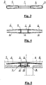
- Fig. 4 shows a side view of the connector according to Fig. 2
- the U-shaped bars 4 comprise extensions of the steel profiles 1,2. This is shown in Fig. 1 and Fig. 2 , as well as in the subsequent figures. However, contrary to solutions known from the prior art, the bends 9 of these bars 4 are pointing outwards. The distance between the bends 9 of bars 5 thus determines the total length of the connector according to the invention, which includes the length of the steel profile 1, 2 and the length of bars 4 comprising its extension towards both sides, attached to the profile.
- the reinforcing bars 4 have a diameter of 12 mm and include the notched surface, while the length of arms of bars 4 to the bend area 9 is 324 mm.
- the free arms of the U-shaped bar 4 are located 32 mm away from each other, while the bending radius 9 is 24 mm.
- the example length of the omega-shaped cross-section steel profile 1, 2 is 300 mm and its dimensions are: width - 58 mm, height - 26 mm.
- a number of the disclosed connectors connecting the terrace slab or a different element with the building or the structure is provided at the junction between the terrace slab 7 and the structural element of the building or of the structure. This is shown and disclosed in patent documents known from the prior art.
- Fig. 5 presents an example embodiment of a connector anchored within a structural element of a building or of a structure in the form of a ferroconcrete ceiling 8 and in a terrace slab 7 on the other side.
- the top level of the ceiling and of the terrace slab 7 are located at the same ordinal.
- the wall of 11 of the building or of the structure, to which the terrace slab 7 is connected, is also shown here.
- the connector includes two U-shaped bars, welded to the top steel profile 1.
- Fig. 6 presents an example embodiment of a connector anchored within a structural element of a building or of a structure in the form of a ferroconcrete ceiling 8 and in a terrace slab 7 on the other side.
- the top level of the ceiling 8 and of the terrace slab 7 are located at the same ordinal.
- the wall of 11 of the building or of the structure, to which the terrace slab 7 is connected, is also shown here.
- the connector includes four bars 4 welded to the top steel profile 1 and to the bottom steel profile 2. In this embodiment, the connector ensures indirect support of the terrace.
- Fig. 7 presents an embodiment of the connector according to Fig. 5 , however, in this embodiment, arms of the bar 4 anchored within the structural element 8 of the building or of the structure in the form of a ceiling are shaped by bending to avoid collision with the known, neighbouring frame placed perpendicular inside the structural element of the building or of the structure, not shown in this figure. In this embodiment, the top level of the ceiling and of the terrace slab 7 are located at the same ordinal, as shown in Fig. 5 .
- Fig. 8 presents another embodiment of a connector anchored within a structural element of a building or of a structure in the form of a ferroconcrete ceiling 8 and in a terrace slab 7 on the other side.
- the ceiling level jumps upwards and is located above the level of the terrace slab 7.
- the connector includes two bars 4, welded to the top steel profile 1.
- the bottom lining 12 of bars 4 inside the ceiling 8 comprising the structural element of the building or of the structure has the minimum thickness of 40 mm in this embodiment.
- Fig. 9 presents another example embodiment of a connector anchored within a structural element of a building or of a structure in the form of a ferroconcrete wall 11 and in a terrace slab 7 on the other side.
- the bar 4 is generally bent downwards at a right angle and anchored inside the wall 11 of the building or of the structure.
- Fig. 10 presents another example embodiment of a connector anchored within a structural element of a building or of a structure in the form of a ferroconcrete wall 11 and in a terrace slab 7 on the other side.
- the bar 4 is generally bent upwards at a right angle and anchored inside the wall 11.
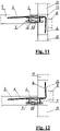
- Fig. 11 shows an embodiment of the connector anchored inside a ferroconcrete beam 13, where the ferroconcrete ceiling 8 may be located at any level.
- the connector is anchored to the terrace slab 7.
- the wall 11 of the building or of the structure is also shown here.
- the connector includes two bars 4, welded to the top steel profile 1.
- the bar 4 anchored inside the ferroconcrete beam 13 is generally bent downwards at a right angle, according to the shape of the beam 13.
- Fig. 12 presents an embodiment of the connector anchored inside a ferroconcrete beam 13, similar to the embodiment shown in Fig. 11 .
- the bar 4 anchored inside the ferroconcrete beam 13 is generally bent upwards at a right angle, according to the shape of the beam 13.
- the ferroconcrete ceiling 8 may be located at any level.
- Fig. 13 presents an embodiment of the connector anchored inside a ferroconcrete beam 13, however, the beam 13 has a different cross-section than that shown in Fig. 11 and Fig. 12 . Because of the cross-section of beam 13 comprising the structural element of the building or of the structure to which the connector should be anchored, the bar 4 anchoring to the beam 13 is bent into a downward oriented loop. Similar to the embodiments shown in Fig. 11 and Fig. 12 , the ferroconcrete ceiling 8 may be located inside the building or the structure at any level.
- Fig. 14 presents another embodiment of the connector anchored inside a ferroconcrete beam 13, similar to the beam shown in Fig. 13 , but with a different cross-section.
- the bar 4 anchoring the connector within the beam 13 is bent into an upwards oriented loop.
Landscapes
- Engineering & Computer Science (AREA)
- Architecture (AREA)
- Physics & Mathematics (AREA)
- Electromagnetism (AREA)
- Civil Engineering (AREA)
- Structural Engineering (AREA)
- Joining Of Building Structures In Genera (AREA)
Abstract
Description
- The subject of the invention is a construction reinforcement connector intended, in particular, for joining an external ferroconcrete panel, a terrace slab in particular, with a ferroconcrete structural element of a building, for example with a ferroconcrete ceiling, a ferroconcrete girder or a wall.
- A range of construction reinforcement connector designs is known in the art, including known solutions containing dedicated thermal insulation elements cooperating with the connector. In buildings and structures, a terrace slab is attached to a structural element using a number of connectors according to the invention.
- In a solution known from the patent disclosure
EP 3613910 , a building connector with thermal insulation is known, which contains at least one pair of load bearing elements, one located above the other, and a thermal insulation layer located around and between such load bearing elements. The load bearing element in this known solution is a section of a steel profile with steel reinforcing bars attached to its both ends, comprising extensions of said profile. The free ends of those bars are an extension of the profile. In this known solution, the steel profile is an open profile with an omega-shaped cross-section, wherein one steel reinforcing bar is attached to each end of this profile, in the bends of its arms. The aforementioned reinforcing bar includes a loop and two arms within its length. The loop covers the spine of the steel profile in this solution. The reinforcing bar is attached within bends of the omega steel profile, between the outwards bent arm and the side wall of the spine of this profile perpendicular to this arm. In a pair of steel profiles comprising a single connector, both profiles are parallel, one located above the other and facing each other with the spines of the omega-shaped profiles. The arms of both omega steel profiles, bent outwards, lie in parallel planes. Within each pair of the omega steel profiles, the middle sections of both profiles are located within the thermal insulation layer. The thermal insulation layer includes three zones. The bottom zone of the insulation layer has a protrusion matching the shape of the interior of the bottom profile spine. The middle insulation zone includes a bottom channel and the top channel meshing with the spines of both steel profiles within this insulation zone. In this known solution, the top insulation zone includes a spine shaped to match the external shape of the top steel profile. In this known solution, each steel bar of the reinforcement has two free ends pointing away from the omega steel profile to which the bar is attached and a loop in its middle section, including the spine of this omega steel profile. Each of the omega steel profiles has one steel bar with the aforementioned loop attached to each of its ends. Two free ends of the steel bar of the reinforcement fixed to the end of the omega steel profile with its loop cooperate with the ferroconcrete structural element of the structure. The second steel bar of the reinforcement, fixed to the second end of this omega steel profile with its loop, cooperates with the ferroconcrete structural element attached to the aforementioned structural element of the structure via a number of the disclosed connectors. The structural element of the structure or building may be a monolithic ceiling or a tie beam. The element attached to the structural element of a structure or a building may be a terrace slab. These two example elements are joined using a number of connectors according to this known solutions, including dedicated thermal insulation in the form of shaped and complementary beams made of structural foam, running across a number of the described connectors. - In a solution according to the international patent application no.
WO 00/47834 - In another known solution, pairs of C-shaped steel profiles are used, penetrating the layer formed of thermally insulating material profiles. Each pair of the C-shaped profiles, the top and the bottom profiles, are connected with a U-shaped reinforcing bar on one side and with a U-shaped reinforcing bar on the other side. An identical connection using two more U-shaped bars is provided on the other side, in the area of the second ends of the same pair of C-shaped profiles. Thus, a pair of C-shaped profiles is connected on each side using two bars, each of which is U-shaped, wherein arms of these bars provide an extension of said C-shaped profiles. Thus placed four bar arms on one side of the pair of C-shaped profile are intended for connection with reinforcement of an external building element, for example of a terrace slab, while four bar arms on the opposite side of the same pair of C-shaped profiles are intended for connection with reinforcement of an internal building element, for example, of a ceiling. Each pair of the C-shaped profiles with the bars, the top and the bottom C-shaped profile, is free of reinforcing bars in the middle section of its length. A range of such pairs of C-shaped profiles with reinforcing bars, comprising connectors, is intended for installation between neighbouring edges of a terrace slab and of a building ceiling.
- In the known solution, the C-shaped profiles in such multiple connector pairs are free of reinforcing elements in the middle section of their length. This area along the edge of the building ceiling and along the edge of the terrace slab is intended for installation of thermal insulation profiles in order to remove a potential thermal bridge.
- The problem to be solved is to increase the resistance of said connector by increasing the structural reliability of welded joints. The problem to be solved also includes improvement of logistics of pre-fabricated panels with installed connectors and improvement of thermal insulation of connections by improving the dimensional accuracy of connector execution. This should result in improvement in terms of further removal of thermal bridges in said areas of connections of external structural elements, such as terrace slabs, for example, with internal structural elements, such as ceiling slabs, for example. In the known structure of the connector, the ends of two steel profiles are connected with a U-shaped reinforcing bar on one side and with a similarly shaped bar on the right side, within the bend area of said bars. The second ends of these steel profiles are connected similarly, using two additional U-shaped bars. Each four ends of said reinforcing bars thus protrude far away from steel profiles, comprising extensions of such profiles to both sides. The attachment of steel profiles to the U-shaped reinforcing bars within the bend area of such bars comprises a difficult to overcome challenge, related to maintaining the dimension repeatability of individual connectors. Reinforcing bars with significant cross-sectional diameters, up to 12 - 16 mm, cause difficulties in maintaining a repeatable distance between steel profiles attached to them during and after welding, within the bend area. Even small differences between dimensions arising during connector welding or after the welding as a result of flexible deformations within the bend area of the U-shaped bars result in loss of tightness in insulation bars laid out within multiple connectors at a construction site. This contributes to formation of thermal bridges inside the final building or a structure. Welding of reinforcing bars with steel profiles near the bends of the previously formed reinforcing bars may also significantly weaken the entire structure of the reinforcing connector. The previously bent bars usually exhibit weaker bend areas, and welding operations in the known solutions were performed exactly in such bend areas of the reinforcing bars. The invention is intended to remove such disadvantages.
- These problems were solved by a change to the configuration of the U-shaped reinforcing bars within the connector. In the previously disclosed solutions, the U-shaped reinforcing bars were located within the connector installed in a building or a structure within a vertical plane. Each of these U-shaped bars was welded to two steel profiles, the top profile and the bottom profile, within the bend area of the bar, while free ends of each of the U-shaped bars protruded outside the connector on both sides.
- On the other hand, the solution according to the invention proposes attaching each of the U-shaped reinforcing bars within a horizontal plane. On both sides of the steel profile, two free ends of each of the two reinforcing bars are welded to the end of the same steel profile, while the bends of said bars protrude outside the connector and outline the reach of said bars. In special cases, the bottom steel profile in the reinforcement connector may lack the welded reinforcing bars. On the other hand, the connection between two profiles in each connector was provided according to the invention by welding straight, vertical bars of specific length between them, two straight vertical bars at one and two vertical bars at the other end of these profiles.
- According to the invention, the construction reinforcement connector contains at least one pair of steel profile sections, one located above the other. A U-shaped reinforcing steel bar is attached to at least one steel profile, at each of its ends, where said steel bars comprise an extension of the profile to both sides. Straight sections of the reinforcing bar connecting the two steel profiles are also attached between the steel profiles, at their ends.
- According to the invention, the construction reinforcement connector is characterised in that two free ends of the U-shaped reinforcing bar are attached to each end of the steel profile and comprise an extension of the steel profile. In the working position of the connector, each of the U-shaped reinforcing bars encompasses the spine of the steel profile with its free ends.
- In the solution according to the invention, the steel profile is preferably an open profile with omega-shaped cross-section.
- The U-shaped reinforcing bar according to the invention is preferably placed in a plane parallel to the plane of arms of the omega-shaped cross-section steel profile.
- In a pair of steel profiles in a connector, both profiles are parallel, one located above the other and preferably facing each other with the spines.
- In a pair of omega-shaped cross-section steel profiles, the profiles are preferably placed such that the arms of both steel profiles bent outward are located in planes parallel to each other.
- In each pair of the steel profiles, the middle sections of both steel profiles, between the attachment points of the reinforcing bars and of the straight bars, are preferably located within the layer of thermal insulation.
- In a preferable embodiment of the solution according to the invention, the reinforcing bars are bent at a right angle at least on one side of the steel profile.
- At least one U-shaped reinforcing bar is bent at at least one point, on one side of the connector, in the area of the extension of the steel profile, according to the shape of the cross-section of the structural element of a building or of a structure in which the connector is installed.
- The proposed solution using omega-shaped cross-section steel profiles enabled the distance between two steel profiles, and thus the size of the connector, to be independent of the length of the welded vertical bars. Depending on the requirements of the designer, execution of connectors of different sizes thus became dependent on the use of straight, unbent vertical bars of the required length, wherein the length of said bars determines the precise dimension of the connector, according to the project of the construction site. The production process of connectors according to the invention has thus been freed of the difficult technological operation of precise bending of the reinforcing bar with a significant cross-section, with the precise, required distance between arms in the area of the bend of such a bar. In known solutions, this distance determined the size of the connector required by the site designer. At the same time and according to this invention, provision of welded joints connecting only straight reinforcing bars with steel profiles eliminated the unfavourable influence of welding on resistance of the joint, previously made weaker by bending the bar.
- The solution according to the invention enables production of larger numbers of individual profiles with U-shaped reinforcing bars attached to them on both sides, to be stored at a warehouse. The same components enable preparation of ready connectors of various sizes, depending on the requirements of the construction site. In the case of the solution according to the invention, these parameters depend only on the length of the straight bars used, which were not previously weakened by bending.
- At the same time, it was shown that the U-shaped reinforcing bar with its bend directed outwards transfers loads much better than two free ends of an identical bar installed with its bend directed towards the steel profiles. In the case of the solution according to the invention, this enabled the required length of the bar, protruding outside both ends of the steel profile, to be shorter. This decreased the external dimension of the connector according to the invention, which in turn facilitated storage and transport of connectors to the construction site.
- The object of the invention has been presented in embodiments in the attached drawing, in which individual figures of the drawing represent as follows:
-
Fig. 1 - a view of the connector with two reinforcing bars. -
Fig. 2 - a view of the connector with four reinforcing bars. -
Fig. 3 - a top view of the connector. -
Fig. 4 - a side view of the connector with four reinforcing bars. -
Fig. 5 - a cross-section through the connector anchored in the ceiling and in the terrace slab, at the same ordinal coordinate. -
Fig. 6 - a cross-section through the connector anchored in a continuous ceiling. -
Fig. 7 - a cross-section through the connector according toFig. 5 , with a reinforcing bar formed because of the collision with reinforcement inside the ceiling. -
Fig. 8 - a cross-section through the connector according toFig. 5 , with the level of the ceiling moving upwards. -
Fig. 9 - a cross-section through the connector anchored in a wall and in the terrace slab, with downward anchoring inside a wall. -
Fig. 10 - a cross-section through the connector according toFig. 9 , with upwards anchoring inside a wall. -
Fig. 11 - a cross-section through the connector according toFig. 10 , with downwards anchoring inside a ferroconcrete beam with any level of the ceiling. -
Fig. 12 - a cross-section through the connector according toFig. 11 , with upwards anchoring inside a ferroconcrete beam -
Fig. 13 - a cross-section through the connector with anchoring inside a ferroconcrete beam using a U-shaped reinforcing bar bent downwards into a loop. -
Fig. 14 - a cross-section through the connector according toFig. 13 with the reinforcing bar bent upwards into a loop. -
Fig. 1 shows the connector according to the invention in the first embodiment, in a perspective view. In this embodiment, the connector includes atop steel profile 1 and abottom steel profile 2.Profiles spines 3.Fig. 1 presents an embodiment of the connector with two U-shaped reinforcing bars 4. In this embodiment, both reinforcingbars 4 are welded to two ends of thetop steel profile 1. It is shown here that each of the reinforcingbars 4 encompasses the terminal part of thespine 3 with its free ends and is welded both to the sides of thisspine 3, and to both arms of the omega-shapedcross-section steel profile - Both
steel profiles bars 5 welded to the sides of thespine 3 of theprofile 1, as well as toarms 6 of thisprofile 1. As it can be seen in this figure, the length ofstraight bars 5 determines the connector height, which may be adjusted by selecting the length of saidstraight bars 5 according to the requirements of the design of the construction project. This figure also shows that the middle section of the length ofsteel profiles Fig 5 to Fig. 14 present this thermal insulation zone intended to remove thermal bridges within the building asitem 10 and its presence is only generally outlined in these figures. -
Fig. 2 presents the second embodiment of the connector according to the invention. In this embodiment, thebottom steel profile 2 is also provided with U-shaped reinforcing bars 4. Each of bothsteel profiles bar 4 welded to its both ends. All four reinforcingbars 4 are attached to four ends of thesteel profiles bars 4 comprise extensions of the terminal parts of each of thesteel profiles ferroconcrete terrace slab 7 on one side, and on the other - with the ferroconcrete structural element of the building or of the structure, for example aceiling 8, to which thisterrace slab 7 is connected. -
Fig. 1 and Fig. 2 , as well as subsequent figures show that theU-shaped bar 4 is located in a generally horizontal plane in this solution. This distinguishes the solution according to the invention from solutions known from the prior art, where each of theU-shaped bars 4 is located in a generally vertical plane. As shown in the figures, in the solution according to the invention each of theU-shaped bars 4 is attached at its free ends to onesteel profile bars 4 is attached at its bent part to twoprofiles bars 4 in an approximately horizontal position and thus the terms generally vertical and generally horizontal were used. This is shown in the followingFig. 3 and Fig. 4 , as well as in the subsequent figures.Fig. 3 shows a top view of the connector according toFig. 1 and Fig. 2 , whileFig. 4 shows a side view of the connector according toFig. 2 - The
U-shaped bars 4 comprise extensions of thesteel profiles Fig. 1 and Fig. 2 , as well as in the subsequent figures. However, contrary to solutions known from the prior art, thebends 9 of thesebars 4 are pointing outwards. The distance between thebends 9 ofbars 5 thus determines the total length of the connector according to the invention, which includes the length of thesteel profile bars 4 comprising its extension towards both sides, attached to the profile. In this embodiment, the reinforcingbars 4 have a diameter of 12 mm and include the notched surface, while the length of arms ofbars 4 to thebend area 9 is 324 mm. The free arms of theU-shaped bar 4 are located 32 mm away from each other, while thebending radius 9 is 24 mm. The example length of the omega-shapedcross-section steel profile - A number of the disclosed connectors connecting the terrace slab or a different element with the building or the structure is provided at the junction between the
terrace slab 7 and the structural element of the building or of the structure. This is shown and disclosed in patent documents known from the prior art. -
Fig. 5 presents an example embodiment of a connector anchored within a structural element of a building or of a structure in the form of aferroconcrete ceiling 8 and in aterrace slab 7 on the other side. In this embodiment, the top level of the ceiling and of theterrace slab 7 are located at the same ordinal. The wall of 11 of the building or of the structure, to which theterrace slab 7 is connected, is also shown here. In this embodiment, the connector includes two U-shaped bars, welded to thetop steel profile 1. -
Fig. 6 presents an example embodiment of a connector anchored within a structural element of a building or of a structure in the form of aferroconcrete ceiling 8 and in aterrace slab 7 on the other side. In this embodiment, the top level of theceiling 8 and of theterrace slab 7 are located at the same ordinal. The wall of 11 of the building or of the structure, to which theterrace slab 7 is connected, is also shown here. In this embodiment, the connector includes fourbars 4 welded to thetop steel profile 1 and to thebottom steel profile 2. In this embodiment, the connector ensures indirect support of the terrace. -
Fig. 7 presents an embodiment of the connector according toFig. 5 , however, in this embodiment, arms of thebar 4 anchored within thestructural element 8 of the building or of the structure in the form of a ceiling are shaped by bending to avoid collision with the known, neighbouring frame placed perpendicular inside the structural element of the building or of the structure, not shown in this figure. In this embodiment, the top level of the ceiling and of theterrace slab 7 are located at the same ordinal, as shown inFig. 5 . -
Fig. 8 presents another embodiment of a connector anchored within a structural element of a building or of a structure in the form of aferroconcrete ceiling 8 and in aterrace slab 7 on the other side. In this embodiment, the ceiling level jumps upwards and is located above the level of theterrace slab 7. In this embodiment, the connector includes twobars 4, welded to thetop steel profile 1. The bottom lining 12 ofbars 4 inside theceiling 8 comprising the structural element of the building or of the structure has the minimum thickness of 40 mm in this embodiment. -
Fig. 9 presents another example embodiment of a connector anchored within a structural element of a building or of a structure in the form of aferroconcrete wall 11 and in aterrace slab 7 on the other side. In this embodiment, thebar 4 is generally bent downwards at a right angle and anchored inside thewall 11 of the building or of the structure. -
Fig. 10 presents another example embodiment of a connector anchored within a structural element of a building or of a structure in the form of aferroconcrete wall 11 and in aterrace slab 7 on the other side. In this embodiment of the invention, contrary to the example shown inFig. 9 , In this embodiment, thebar 4 is generally bent upwards at a right angle and anchored inside thewall 11. -
Fig. 11 shows an embodiment of the connector anchored inside aferroconcrete beam 13, where theferroconcrete ceiling 8 may be located at any level. On the other side, the connector is anchored to theterrace slab 7. Thewall 11 of the building or of the structure is also shown here. In this embodiment, the connector includes twobars 4, welded to thetop steel profile 1. Thebar 4 anchored inside theferroconcrete beam 13 is generally bent downwards at a right angle, according to the shape of thebeam 13. -
Fig. 12 presents an embodiment of the connector anchored inside aferroconcrete beam 13, similar to the embodiment shown inFig. 11 . In this embodiment, however, thebar 4 anchored inside theferroconcrete beam 13 is generally bent upwards at a right angle, according to the shape of thebeam 13. Similar to the embodiment shown infig. 11 , theferroconcrete ceiling 8 may be located at any level. -
Fig. 13 presents an embodiment of the connector anchored inside aferroconcrete beam 13, however, thebeam 13 has a different cross-section than that shown inFig. 11 and Fig. 12 . Because of the cross-section ofbeam 13 comprising the structural element of the building or of the structure to which the connector should be anchored, thebar 4 anchoring to thebeam 13 is bent into a downward oriented loop. Similar to the embodiments shown inFig. 11 and Fig. 12 , theferroconcrete ceiling 8 may be located inside the building or the structure at any level. -
Fig. 14 presents another embodiment of the connector anchored inside aferroconcrete beam 13, similar to the beam shown inFig. 13 , but with a different cross-section. In this embodiment, thebar 4 anchoring the connector within thebeam 13 is bent into an upwards oriented loop. - In all embodiments shown in
Fig. 7 and inFig. 9 to Fig. 14 , where thebar 4 is shown as bent, the bend applies to both arms of theU-shaped bar 4. Both bent arms of thisbar 4 remain generally parallel, as shown in the listedfig. 7 and inFig. 9 to Fig. 14 . - In other embodiments of the connector according to the invention, different dimensions or cross-sections of
steel profiles bars 4 andstraight bars 5 may be used. The indicated locations ofbars 4 in structural elements of the building or of the structure are exemplary and do not exclude other embodiments of the connector according to the invention. Omega-shaped cross-section steel profiles shown in the embodiments also should be considered as preferable and not excluding the use of steel profiles with different cross-sections. -
- 1. Top steel profile.
- 2. Bottom steel profile.
- 3. Profile spine.
- 4. U-shaped reinforcing bar.
- 5. Straight bar.
- 6. Profile arm.
- 7. Terrace slab.
- 8. Ceiling.
- 9. Bend.
- 10. Thermal insulation.
- 11. Wall of the building/structure
- 12. Bottom lining.
- 13. Ferroconcrete beam.
Claims (8)
- A construction reinforcement connector including at least one pair of steel profile (1,2) sections located one above the other, wherein to at least one steel profile (1, 2), on each side, a U-shaped steel reinforcing bar (4) is attached, wherein said reinforcement bars (4) are an extension of this profile (1, 2) to both sides, and between these steel profiles (1, 2), at their ends, straight sections of the reinforcing bar (5) are also attached and connect these two steel profiles (1, 2), characterised in that, two free ends of the U-shaped reinforcing bar (4) comprising an extension of the steel profile (1,2) are attached to each end of the steel profile (1, 2), wherein in the working position of the connector, each of the U-shaped bars (4) encompasses the spine (3) of the steel profile with its ends.
- A construction connector according to claim 1, characterised in that the steel profile (1,2) is an omega-shaped cross-section open profile.
- A construction connector according to claim 2, characterised in that the U-shaped reinforcing bar (4) is located in a plane parallel to the plane of arms of the steel profile (1, 2).
- A construction connector according to claim 1 or 2 or 3, characterised in that in a pair of steel profiles (1, 2) in a connector, both profiles (1,2) are parallel, one located above the other, and facing each other with the spines (3).
- A construction connector according to claim 4, characterised in that in a pair of omega-shaped cross-section steel profiles (1, 2), the profiles are placed such that the arms of both steel profiles (1,2) bent outward are located in planes parallel to each other.
- A construction connector according to any of the claims 1 to 5, characterised in that in each pair of the profiles (1, 2), the middle section of both such steel profiles (1, 2), are located within the layer of thermal insulation (10), between the connection points of the reinforcing bars (4) and the connection points of straight bars (5).
- A construction connector according to any of the claims 1 to 6, characterised in that the reinforcing bars (4) are bent at the right angle at least on one side of the steel profile (1, 2).
- A construction connector according to any of the claims 1 to 6, characterised in that at least one reinforcing bar (4) on one side of the connector, in the zone of steel profile (1, 2) extension is bent at at least one point, according to the shape of the cross-section of the structural element of the building or of the structure, where the connector is attached.
Priority Applications (2)
| Application Number | Priority Date | Filing Date | Title |
|---|---|---|---|
| EP21460015.7A EP4047147B1 (en) | 2021-02-19 | 2021-02-19 | Construction reinforcement connector |
| PL21460015.7T PL4047147T3 (en) | 2021-02-19 | 2021-02-19 | Construction reinforcement connector |
Applications Claiming Priority (1)
| Application Number | Priority Date | Filing Date | Title |
|---|---|---|---|
| EP21460015.7A EP4047147B1 (en) | 2021-02-19 | 2021-02-19 | Construction reinforcement connector |
Publications (3)
| Publication Number | Publication Date |
|---|---|
| EP4047147A1 true EP4047147A1 (en) | 2022-08-24 |
| EP4047147B1 EP4047147B1 (en) | 2023-09-13 |
| EP4047147C0 EP4047147C0 (en) | 2023-09-13 |
Family
ID=75581484
Family Applications (1)
| Application Number | Title | Priority Date | Filing Date |
|---|---|---|---|
| EP21460015.7A Active EP4047147B1 (en) | 2021-02-19 | 2021-02-19 | Construction reinforcement connector |
Country Status (2)
| Country | Link |
|---|---|
| EP (1) | EP4047147B1 (en) |
| PL (1) | PL4047147T3 (en) |
Cited By (1)
| Publication number | Priority date | Publication date | Assignee | Title |
|---|---|---|---|---|
| EP4775751A1 (en) | 2025-01-14 | 2026-07-15 | Tipomega P.S.A. | Load-bearing frame of a construction connector |
Citations (4)
| Publication number | Priority date | Publication date | Assignee | Title |
|---|---|---|---|---|
| DE20003008U1 (en) * | 2000-02-18 | 2000-04-27 | Mea Meisinger Stahl und Kunststoff GmbH, 86551 Aichach | Mounting bracket system |
| WO2000047834A1 (en) | 1999-02-12 | 2000-08-17 | Avi Alpenländische Veredelungs-Industrie Gesellschaft M.B.H. | Device for attaching cantilever plates to a wall construction or a ceiling construction |
| EP1881119A2 (en) * | 2006-07-21 | 2008-01-23 | Pontarolo Engineering S.p.a. | Support bracket for overhanging building elements |
| EP3613910A1 (en) | 2018-08-22 | 2020-02-26 | iBALKON Dariusz Glaza | Building connector with thermal insulation |
-
2021
- 2021-02-19 EP EP21460015.7A patent/EP4047147B1/en active Active
- 2021-02-19 PL PL21460015.7T patent/PL4047147T3/en unknown
Patent Citations (4)
| Publication number | Priority date | Publication date | Assignee | Title |
|---|---|---|---|---|
| WO2000047834A1 (en) | 1999-02-12 | 2000-08-17 | Avi Alpenländische Veredelungs-Industrie Gesellschaft M.B.H. | Device for attaching cantilever plates to a wall construction or a ceiling construction |
| DE20003008U1 (en) * | 2000-02-18 | 2000-04-27 | Mea Meisinger Stahl und Kunststoff GmbH, 86551 Aichach | Mounting bracket system |
| EP1881119A2 (en) * | 2006-07-21 | 2008-01-23 | Pontarolo Engineering S.p.a. | Support bracket for overhanging building elements |
| EP3613910A1 (en) | 2018-08-22 | 2020-02-26 | iBALKON Dariusz Glaza | Building connector with thermal insulation |
Cited By (1)
| Publication number | Priority date | Publication date | Assignee | Title |
|---|---|---|---|---|
| EP4775751A1 (en) | 2025-01-14 | 2026-07-15 | Tipomega P.S.A. | Load-bearing frame of a construction connector |
Also Published As
| Publication number | Publication date |
|---|---|
| PL4047147T3 (en) | 2024-03-04 |
| EP4047147B1 (en) | 2023-09-13 |
| EP4047147C0 (en) | 2023-09-13 |
Similar Documents
| Publication | Publication Date | Title |
|---|---|---|
| US8281534B2 (en) | Formed steel beam for steel-concrete composite beam and slab | |
| US8733055B2 (en) | Masonry with steel reinforcement strip having spacers | |
| KR20110032687A (en) | Construction method of steel beams with steel or steel reinforced concrete columns and end reinforced with reinforced concrete | |
| KR102443153B1 (en) | Composite Beam with H-Shaped Steel for Layer Savings | |
| KR100947340B1 (en) | Shear reinforcement of slab and column connection and manufacturing method | |
| KR102641227B1 (en) | Steel Reinforced Concrete Clolumn | |
| EP4047147B1 (en) | Construction reinforcement connector | |
| EP3613910B1 (en) | Building connector with thermal insulation | |
| US4586307A (en) | Prefabricated ceiling element for ceilings in buildings | |
| KR200469319Y1 (en) | Construction structure for joining steel or reinforced steel concrete column and beam with reinforcing end part | |
| EP3861179B1 (en) | Precast concrete panel joining system, method of making a panel joint, panel joint obtained by the method | |
| KR101900310B1 (en) | Pre-fabricated column structure with l-type steel material | |
| KR102499284B1 (en) | Curved Beam Structures for Rampway | |
| KR101526141B1 (en) | Buckstay system | |
| EP1416101A1 (en) | Composite beam | |
| KR100340115B1 (en) | T-shape PC slab dap end and method for constructing structure using the same | |
| KR102091436B1 (en) | Shear reinforcement for reinforced concrete walls and the installation method thereof | |
| EP4230801B1 (en) | Foundation element and building foundation | |
| CN107119802B (en) | Connecting method of skin steel plates | |
| KR20100090553A (en) | Multi-slab and construction method using the proposed | |
| KR102656176B1 (en) | A T-type unit using H-beam and a composite structure system with reduced floor height combined with a steel plate built-up composite column and composite beam | |
| JP7482587B2 (en) | Joint structure of precast concrete slab members and method for constructing concrete slab structure | |
| JP7658603B2 (en) | Deck Plates and Deck Plate Assemblies | |
| KR200294416Y1 (en) | Prestressed cold-formed joist having reinforcement materials | |
| KR100381411B1 (en) | Modified T-shape PC slab which include service duct in the web of slab and method for constructing structure using the same |
Legal Events
| Date | Code | Title | Description |
|---|---|---|---|
| PUAI | Public reference made under article 153(3) epc to a published international application that has entered the european phase |
Free format text: ORIGINAL CODE: 0009012 |
|
| STAA | Information on the status of an ep patent application or granted ep patent |
Free format text: STATUS: THE APPLICATION HAS BEEN PUBLISHED |
|
| AK | Designated contracting states |
Kind code of ref document: A1 Designated state(s): AL AT BE BG CH CY CZ DE DK EE ES FI FR GB GR HR HU IE IS IT LI LT LU LV MC MK MT NL NO PL PT RO RS SE SI SK SM TR |
|
| STAA | Information on the status of an ep patent application or granted ep patent |
Free format text: STATUS: REQUEST FOR EXAMINATION WAS MADE |
|
| RAP3 | Party data changed (applicant data changed or rights of an application transferred) |
Owner name: IBALKON DARIUSZ GLAZA |
|
| 17P | Request for examination filed |
Effective date: 20221223 |
|
| RBV | Designated contracting states (corrected) |
Designated state(s): AL AT BE BG CH CY CZ DE DK EE ES FI FR GB GR HR HU IE IS IT LI LT LU LV MC MK MT NL NO PL PT RO RS SE SI SK SM TR |
|
| RAP3 | Party data changed (applicant data changed or rights of an application transferred) |
Owner name: IBALKON DARIUSZ GLAZA |
|
| GRAP | Despatch of communication of intention to grant a patent |
Free format text: ORIGINAL CODE: EPIDOSNIGR1 |
|
| STAA | Information on the status of an ep patent application or granted ep patent |
Free format text: STATUS: GRANT OF PATENT IS INTENDED |
|
| INTG | Intention to grant announced |
Effective date: 20230508 |
|
| GRAS | Grant fee paid |
Free format text: ORIGINAL CODE: EPIDOSNIGR3 |
|
| GRAA | (expected) grant |
Free format text: ORIGINAL CODE: 0009210 |
|
| STAA | Information on the status of an ep patent application or granted ep patent |
Free format text: STATUS: THE PATENT HAS BEEN GRANTED |
|
| AK | Designated contracting states |
Kind code of ref document: B1 Designated state(s): AL AT BE BG CH CY CZ DE DK EE ES FI FR GB GR HR HU IE IS IT LI LT LU LV MC MK MT NL NO PL PT RO RS SE SI SK SM TR |
|
| REG | Reference to a national code |
Ref country code: CH Ref legal event code: EP |
|
| REG | Reference to a national code |
Ref country code: DE Ref legal event code: R096 Ref document number: 602021005154 Country of ref document: DE |
|
| REG | Reference to a national code |
Ref country code: IE Ref legal event code: FG4D |
|
| U01 | Request for unitary effect filed |
Effective date: 20231010 |
|
| U07 | Unitary effect registered |
Designated state(s): AT BE BG DE DK EE FI FR IT LT LU LV MT NL PT SE SI Effective date: 20231016 |
|
| PG25 | Lapsed in a contracting state [announced via postgrant information from national office to epo] |
Ref country code: GR Free format text: LAPSE BECAUSE OF FAILURE TO SUBMIT A TRANSLATION OF THE DESCRIPTION OR TO PAY THE FEE WITHIN THE PRESCRIBED TIME-LIMIT Effective date: 20231214 |
|
| PG25 | Lapsed in a contracting state [announced via postgrant information from national office to epo] |
Ref country code: RS Free format text: LAPSE BECAUSE OF FAILURE TO SUBMIT A TRANSLATION OF THE DESCRIPTION OR TO PAY THE FEE WITHIN THE PRESCRIBED TIME-LIMIT Effective date: 20230913 Ref country code: NO Free format text: LAPSE BECAUSE OF FAILURE TO SUBMIT A TRANSLATION OF THE DESCRIPTION OR TO PAY THE FEE WITHIN THE PRESCRIBED TIME-LIMIT Effective date: 20231213 Ref country code: HR Free format text: LAPSE BECAUSE OF FAILURE TO SUBMIT A TRANSLATION OF THE DESCRIPTION OR TO PAY THE FEE WITHIN THE PRESCRIBED TIME-LIMIT Effective date: 20230913 Ref country code: GR Free format text: LAPSE BECAUSE OF FAILURE TO SUBMIT A TRANSLATION OF THE DESCRIPTION OR TO PAY THE FEE WITHIN THE PRESCRIBED TIME-LIMIT Effective date: 20231214 |
|
| U20 | Renewal fee for the european patent with unitary effect paid |
Year of fee payment: 4 Effective date: 20231222 |
|
| PG25 | Lapsed in a contracting state [announced via postgrant information from national office to epo] |
Ref country code: IS Free format text: LAPSE BECAUSE OF FAILURE TO SUBMIT A TRANSLATION OF THE DESCRIPTION OR TO PAY THE FEE WITHIN THE PRESCRIBED TIME-LIMIT Effective date: 20240113 |
|
| PG25 | Lapsed in a contracting state [announced via postgrant information from national office to epo] |
Ref country code: ES Free format text: LAPSE BECAUSE OF FAILURE TO SUBMIT A TRANSLATION OF THE DESCRIPTION OR TO PAY THE FEE WITHIN THE PRESCRIBED TIME-LIMIT Effective date: 20230913 |
|
| PG25 | Lapsed in a contracting state [announced via postgrant information from national office to epo] |
Ref country code: SM Free format text: LAPSE BECAUSE OF FAILURE TO SUBMIT A TRANSLATION OF THE DESCRIPTION OR TO PAY THE FEE WITHIN THE PRESCRIBED TIME-LIMIT Effective date: 20230913 Ref country code: RO Free format text: LAPSE BECAUSE OF FAILURE TO SUBMIT A TRANSLATION OF THE DESCRIPTION OR TO PAY THE FEE WITHIN THE PRESCRIBED TIME-LIMIT Effective date: 20230913 Ref country code: IS Free format text: LAPSE BECAUSE OF FAILURE TO SUBMIT A TRANSLATION OF THE DESCRIPTION OR TO PAY THE FEE WITHIN THE PRESCRIBED TIME-LIMIT Effective date: 20240113 Ref country code: ES Free format text: LAPSE BECAUSE OF FAILURE TO SUBMIT A TRANSLATION OF THE DESCRIPTION OR TO PAY THE FEE WITHIN THE PRESCRIBED TIME-LIMIT Effective date: 20230913 Ref country code: CZ Free format text: LAPSE BECAUSE OF FAILURE TO SUBMIT A TRANSLATION OF THE DESCRIPTION OR TO PAY THE FEE WITHIN THE PRESCRIBED TIME-LIMIT Effective date: 20230913 Ref country code: SK Free format text: LAPSE BECAUSE OF FAILURE TO SUBMIT A TRANSLATION OF THE DESCRIPTION OR TO PAY THE FEE WITHIN THE PRESCRIBED TIME-LIMIT Effective date: 20230913 |
|
| REG | Reference to a national code |
Ref country code: DE Ref legal event code: R097 Ref document number: 602021005154 Country of ref document: DE |
|
| PLBE | No opposition filed within time limit |
Free format text: ORIGINAL CODE: 0009261 |
|
| STAA | Information on the status of an ep patent application or granted ep patent |
Free format text: STATUS: NO OPPOSITION FILED WITHIN TIME LIMIT |
|
| RAP2 | Party data changed (patent owner data changed or rights of a patent transferred) |
Owner name: TIPOMEGA P.S.A. |
|
| U1K | Transfer of rights of the unitary patent after the registration of the unitary effect |
Owner name: TIPOMEGA P.S.A.; PL |
|
| 26N | No opposition filed |
Effective date: 20240614 |
|
| PG25 | Lapsed in a contracting state [announced via postgrant information from national office to epo] |
Ref country code: MC Free format text: LAPSE BECAUSE OF FAILURE TO SUBMIT A TRANSLATION OF THE DESCRIPTION OR TO PAY THE FEE WITHIN THE PRESCRIBED TIME-LIMIT Effective date: 20230913 |
|
| REG | Reference to a national code |
Ref country code: CH Ref legal event code: PL |
|
| PG25 | Lapsed in a contracting state [announced via postgrant information from national office to epo] |
Ref country code: CH Free format text: LAPSE BECAUSE OF NON-PAYMENT OF DUE FEES Effective date: 20240229 |
|
| PG25 | Lapsed in a contracting state [announced via postgrant information from national office to epo] |
Ref country code: CH Free format text: LAPSE BECAUSE OF NON-PAYMENT OF DUE FEES Effective date: 20240229 |
|
| PG25 | Lapsed in a contracting state [announced via postgrant information from national office to epo] |
Ref country code: IE Free format text: LAPSE BECAUSE OF NON-PAYMENT OF DUE FEES Effective date: 20240219 |
|
| PG25 | Lapsed in a contracting state [announced via postgrant information from national office to epo] |
Ref country code: IE Free format text: LAPSE BECAUSE OF NON-PAYMENT OF DUE FEES Effective date: 20240219 |
|
| U20 | Renewal fee for the european patent with unitary effect paid |
Year of fee payment: 5 Effective date: 20250218 |
|
| PG25 | Lapsed in a contracting state [announced via postgrant information from national office to epo] |
Ref country code: CY Free format text: LAPSE BECAUSE OF FAILURE TO SUBMIT A TRANSLATION OF THE DESCRIPTION OR TO PAY THE FEE WITHIN THE PRESCRIBED TIME-LIMIT; INVALID AB INITIO Effective date: 20210219 |
|
| PG25 | Lapsed in a contracting state [announced via postgrant information from national office to epo] |
Ref country code: HU Free format text: LAPSE BECAUSE OF FAILURE TO SUBMIT A TRANSLATION OF THE DESCRIPTION OR TO PAY THE FEE WITHIN THE PRESCRIBED TIME-LIMIT; INVALID AB INITIO Effective date: 20210219 |
|
| GBPC | Gb: european patent ceased through non-payment of renewal fee |
Effective date: 20250219 |
|
| PG25 | Lapsed in a contracting state [announced via postgrant information from national office to epo] |
Ref country code: TR Free format text: LAPSE BECAUSE OF FAILURE TO SUBMIT A TRANSLATION OF THE DESCRIPTION OR TO PAY THE FEE WITHIN THE PRESCRIBED TIME-LIMIT Effective date: 20230913 |
|
| PG25 | Lapsed in a contracting state [announced via postgrant information from national office to epo] |
Ref country code: GB Free format text: LAPSE BECAUSE OF NON-PAYMENT OF DUE FEES Effective date: 20250219 |
|
| PGFP | Annual fee paid to national office [announced via postgrant information from national office to epo] |
Ref country code: PL Payment date: 20251014 Year of fee payment: 6 |
|
| U20 | Renewal fee for the european patent with unitary effect paid |
Year of fee payment: 6 Effective date: 20260128 |