EP4047111A1 - Procédé de fonctionnement d'un électrolyseur du type à empilement de cellules et agencement d'électrolyseur - Google Patents
Procédé de fonctionnement d'un électrolyseur du type à empilement de cellules et agencement d'électrolyseur Download PDFInfo
- Publication number
- EP4047111A1 EP4047111A1 EP21158756.3A EP21158756A EP4047111A1 EP 4047111 A1 EP4047111 A1 EP 4047111A1 EP 21158756 A EP21158756 A EP 21158756A EP 4047111 A1 EP4047111 A1 EP 4047111A1
- Authority
- EP
- European Patent Office
- Prior art keywords
- electrolyzer
- cell
- measuring
- switch
- wiring
- Prior art date
- Legal status (The legal status is an assumption and is not a legal conclusion. Google has not performed a legal analysis and makes no representation as to the accuracy of the status listed.)
- Pending
Links
- 238000000034 method Methods 0.000 title claims abstract description 12
- 238000005259 measurement Methods 0.000 claims abstract description 12
- 238000010276 construction Methods 0.000 description 4
- 238000004880 explosion Methods 0.000 description 3
- 238000009413 insulation Methods 0.000 description 2
- 230000007774 longterm Effects 0.000 description 2
- UFHFLCQGNIYNRP-UHFFFAOYSA-N Hydrogen Chemical compound [H][H] UFHFLCQGNIYNRP-UHFFFAOYSA-N 0.000 description 1
- 238000013459 approach Methods 0.000 description 1
- 238000013475 authorization Methods 0.000 description 1
- 230000006866 deterioration Effects 0.000 description 1
- 230000001627 detrimental effect Effects 0.000 description 1
- 238000011161 development Methods 0.000 description 1
- 238000005868 electrolysis reaction Methods 0.000 description 1
- 238000013213 extrapolation Methods 0.000 description 1
- 229910052739 hydrogen Inorganic materials 0.000 description 1
- 239000001257 hydrogen Substances 0.000 description 1
- 238000012423 maintenance Methods 0.000 description 1
- 238000012986 modification Methods 0.000 description 1
- 230000004048 modification Effects 0.000 description 1
- 238000012544 monitoring process Methods 0.000 description 1
- XLYOFNOQVPJJNP-UHFFFAOYSA-N water Substances O XLYOFNOQVPJJNP-UHFFFAOYSA-N 0.000 description 1
Images

Classifications
-
- C—CHEMISTRY; METALLURGY
- C25—ELECTROLYTIC OR ELECTROPHORETIC PROCESSES; APPARATUS THEREFOR
- C25B—ELECTROLYTIC OR ELECTROPHORETIC PROCESSES FOR THE PRODUCTION OF COMPOUNDS OR NON-METALS; APPARATUS THEREFOR
- C25B15/00—Operating or servicing cells
- C25B15/02—Process control or regulation
- C25B15/023—Measuring, analysing or testing during electrolytic production
-
- C—CHEMISTRY; METALLURGY
- C25—ELECTROLYTIC OR ELECTROPHORETIC PROCESSES; APPARATUS THEREFOR
- C25B—ELECTROLYTIC OR ELECTROPHORETIC PROCESSES FOR THE PRODUCTION OF COMPOUNDS OR NON-METALS; APPARATUS THEREFOR
- C25B1/00—Electrolytic production of inorganic compounds or non-metals
- C25B1/01—Products
- C25B1/02—Hydrogen or oxygen
- C25B1/04—Hydrogen or oxygen by electrolysis of water
-
- C—CHEMISTRY; METALLURGY
- C25—ELECTROLYTIC OR ELECTROPHORETIC PROCESSES; APPARATUS THEREFOR
- C25B—ELECTROLYTIC OR ELECTROPHORETIC PROCESSES FOR THE PRODUCTION OF COMPOUNDS OR NON-METALS; APPARATUS THEREFOR
- C25B9/00—Cells or assemblies of cells; Constructional parts of cells; Assemblies of constructional parts, e.g. electrode-diaphragm assemblies; Process-related cell features
- C25B9/60—Constructional parts of cells
- C25B9/65—Means for supplying current; Electrode connections; Electric inter-cell connections
-
- C—CHEMISTRY; METALLURGY
- C25—ELECTROLYTIC OR ELECTROPHORETIC PROCESSES; APPARATUS THEREFOR
- C25B—ELECTROLYTIC OR ELECTROPHORETIC PROCESSES FOR THE PRODUCTION OF COMPOUNDS OR NON-METALS; APPARATUS THEREFOR
- C25B9/00—Cells or assemblies of cells; Constructional parts of cells; Assemblies of constructional parts, e.g. electrode-diaphragm assemblies; Process-related cell features
- C25B9/70—Assemblies comprising two or more cells
Definitions
- the invention is related to a method of operating an electrolyzer of the cell-stack type, wherein the respective cell voltage of at least two different cells of the cell-stack is measured, as well as an electrolyzer arrangement having such an electrolyzer and cell voltage measuring device.
- Such electrolyzers of the cell-stack type are well-known and f.i. disclosed in DE 10 2014 010 813 A1 Further, it is known that the performance of such electrolyzer may decrease in case of deterioration of the cells, recognizable in a drop of the cell voltage.
- the cell voltage of the cells of the electrolyzer is measured.
- the invention aims to improve electrolyzer arrangements having a measuring device for measuring the cell voltage.
- the long-term performance of the electrolyzer is improved by provision of a more reliable and easier performable approach to measure the cell voltages.
- the fixedly wiring of the cells, respectively their electrodes, allow for cell voltage measuring without the need for an operator to directly access the electrodes f.i. with a portable measuring device. Rather, the wiring permits cell voltage measurement from a distance. Moreover, by having the common wiring path segment, the measuring device needs only a lower number of analog inputs, saving wiring effort and allowing a simpler construction of the measuring device.
- the electrolyzer is performing water electrolysis to produce hydrogen.
- the measuring of the cell voltages can be performed during such operation.
- the switch over of the switching could be done manually. It is, however, also envisaged that the switching occurs according to a preset sequence. Such sequence could, f.i., start for the electrode closest to an end plate, f.i. cathode-side end plate is f.i. grounded, to then follow the electrodes in the ranking of their arrangement from said one end plate to the other end plate.
- the number of cells of the electrolyzer is more than 30, preferably more than 50, in particular more than 60.
- Even larger electrolyzer with 128 cells or more, 150 cells or more and even 192 cells or more are envisaged.
- the switching is a mechanical switching, f.i. by a rotary switch.
- an electronic switching by multiplexing is also envisaged to switch over between the wiring of 100 cells or more, directing their signals over the same common path segment.
- the switching time from sending a measuring signal from one electrode to the common wiring path segment to sending a measuring signal from another electrode to the common wiring path segment is preferably less than 30 min, more preferably less than 10 min, in particular less than 5 min. Also even shorter switching times can be applied, f.i. 1 min or less, 40 sec or less, or even 20 sec or less.
- the wiring is connected to a plurality, in particular all electrodes of the electrolyzer.
- one switch and one only common wiring path segment is used.
- the electrodes of the electrolyzer can be allocated into 2, 3, 4, or even more groups, and there is one switch and one common wiring path for each group. This still reduces the number of analog inputs of the measuring device, which could be provided in the framework of a programmable logic controller. This could reduce the complexity of the multiplexing against provision of a plurality of devices.
- the groups could contain a number of not more than 64 cells, not more 32 cells, or not more than 16 cells.
- the switching is performed at a first location, and the obtaining of the measuring results is performed at a second location spaced apart and being in particular more distant to the electrolyzer than the first location. This may further reduce the overall wiring length of the wiring between the electrodes of the electrolyzer and the switch.
- each single cable for the wiring has a length of not more than 5 m, in particular 3 m.
- the voltage measuring itself could be performed close to the switch, and even be contained within the same housing with the switch, in a preferred embodiment, separate units are provided at different locations. Further, preferably the distance of the location of the voltage measurement is more distant from the electrolyzer than the location of the switching.
- the measurement of all cell voltages is repeatedly performed in particular at regular or selectable intervals, and measuring results are monitored, in particular stored and in particular sent to an analysis module.
- This provides for reliable surveillance of the status of the cells. Further, by extrapolation means considering not only the actual cell voltage but also their first and possibly even second derivative in combination with threshold values, prognostics can be made as to when one or more of the cells should be subject to maintenance or when other measures should be taken, as f.i. bridging a detrimental cell.
- cell voltage measurement for all cells is effected at least once every two months, preferably at least once every month, more preferably at least once every two weeks.
- a measuring sequence of at least once a week, at least once every three days, at least once a day Due to the ease of operation, the system can even be used as diagnostic for singular events detrimentally affecting a cell, by having the measuring sequence being at least once every 12h, at least once every 8h, even at least every 4h. Also a continuous surveillance where one sequence through the cells follows the previous with delay of less than 2h is envisaged.
- the invention provides such electrolyzer arrangement, comprising an electrolyzer of the cell-stack type and a measuring device for measuring the cell voltage of at least two different cells of the cell stack, which is essentially characterized by a wiring connecting electrodes of the cells with the measuring device, the wiring being fixedly connected to the electrodes, and by an in particular automated switch channelling measuring signal allocated for measurement for different cells in a time-shifted manner with respect to each other via a common wiring path segment.
- the electrolyzer can be built up by a certain number of insulated polymeric cells connected by a metallic electrode.
- the electrodes are formed by bipolar plates arranged between respective two neighbored cell frames. That is, an electrolyzer construction as f.i. disclosed in DE 10 2014 010 813 A1 can be used.
- the invention is not limited to such kind of electrolyzers, the above document DE 10 2014 010 813 A1 being incorporated by reference for the general construction/function and arrangement of the electrolyzer cells (that is, irrespective of details of single elements); also other kind of electrolyzers of the staple type can form the electrolyzer of the electrolyzer arrangement.
- the switch is preferably an electronic multiplexer, wherein it is also envisaged to use a plurality of multiplexer, each one for each allocated subgroup of the cells of the electrolyzer.
- the switch is arranged in an encapsulated surrounding.
- an explosion-proof housing is provided, in which the electronic for the switching is received.
- explosion-proofness according to ATEX2014/34/EU is covering explosion group IIC. Further, it is preferably adapted at least for zone 2, possibly also zone 1, or zone 0.
- the housing can be certified by an authorized body and may contain an element which is indicative for granted authorization in a first state and can assume an irreversibly changed state caused by modification of the housing.
- the sensible electronics is protected even when arranged close to the electrolyzer and within an outer housing for the electrolyzer.
- the wiring between the encapsulated surrounding and the electrolyzer is protected.
- Said protection is provided preferably by double insulation and/or short circuit proof cables, preferably with protection level not inferior to that of a NSGAFOU cable.
- the cables may have a flame resistant insulation according to VDE 0250-602. It is understood that also wiring from the output of the switching, in particular the common wiring path segment may be at least partly protected, preferably fully protected as described above.
- the voltage measuring itself can be provided at a location (second location) different of that of the switching, and can be implemented in the framework of a programmable logic controller.
- This PLC can be incorporated into an overall control device for the electrolyzer or an enhanced system comprising not only the electrolyzer but also a rectifier connected to the electrolyzer and the connecting system connecting the rectifier with the electrolyzer.
- the electrolyzer is housed within an (outer) housing, and preferably also the multiplexer is housed within said housing, and the voltage measuring f.i. within the framework of a PLC is outside said housing.
- the above mentioned explosion-proof properties may apply.
- a reference potential can be used, f.i. that of an end plate of the electrolyzer, which could be the, in particular ground, cathode-side end plate of the electrolyzer, and a respective wiring can be present from said end plate to the voltage measuring.
- cell voltage is measured against the neighbor cell.
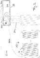
- an electrolyzer 10 of an electrolyzer arrangement 100 is shown.
- the electrolyzer 10 is of the stapled type, comprising a number of n cells stacked along a staple axis extending between two end plates 1, 2 of the electrolyzer 10.
- cell frames 3 alternate with electrodes 4 radially extending at least partially out of the outer shell of cell frames 3.
- Each electrode 4, for the subject exemplary embodiment formed by a bipolar plate, is wired. Construction and regular operation of electrolyzer 10 is well known in the art and not further described here. Rather, reference is made to typical electrolyzers of the staple type, as f.i. disclosed in DE 10 2014 010 813 A1 .
- Multiplexer 30 provides that only one U-signal at a time from said U-inputs is transmitted via wiring path segment 34 to measure the voltage of said electrode against a reference value, which can be that of an end plate ( Fig. 2 ) of the electrolyzer, and in particular ground. Thereby, one after another the cell voltage of each cell of the electrolzyer 10 can be measured.
- the multiplexer 30 could provide for switching from one U-input to the next after a time sufficient for voltage determination, f.i. every ten seconds.
- the cell voltage measurement itself is done within a programmable logic control (PLC) 40. Due to the multiplexer 30 set between the electrolyzer 10 and PLC 40, PLC 40 does not need to have a large number of analog inputs. For instance for an electrolzyer 10 having 64 cells, and a multiplexer multiplexing 64 U-inputs, only one analog input for these 64 cell voltages is required.
- the system further comprises a not-shown (long term) data logging system monitoring the cell voltages. Thereby, the cell voltage for each cell can be monitored on shorter time scales, in particular continuously on a scale of the necessary time to multiplex through all U-inputs of multiplexer 30, f.i. about every ten minutes for the example of 64 cells and 10s switching time. However, such close meshing is optional, and other suitable intervals can be selected, as f.i. one check every hour, one check any couple of hours, or one check a day.
- Fig. 2 it is additionally shown that the multiplexer 30, represented in Fig. 2 as rotary switch, to show the principle of the electronic multiplexer on the one hand side and a possible mechanical implementation of the switch over on the other hand side, is arranged in an explosion-proof housing 38.
- the multiplexer 30/switch is protected against explosion risks arising from problems with the electrolyzer.
- the wiring to and from the surroundings 37 of the multiplexer 30 encapsulated by housing 38 are protected, in the shown embodiment, short circuit-proof cables, f.i. NSGAFOU cables are used.
- At least part of the electrolyzer arrangement comprising the electrolyzer 10, wiring 20, and multiplexer 30 including housing 38 can be placed in a risk area for explosion (EX area, EX IIC).
- the voltage measuring itself in the subject embodiment by PLC 40, could be done at the same location as within the surroundings 37, and even encapsulated by the same housing 38.
- the voltage measuring hereby PLC 40, is done at another location distant from housing 38 and in particular more distant from the electrolyzer than housing 38.
- the part 34b of the common wiring path segment 34 leading to PLC 40 can also be provided by f.i. the NSGAFOU cable.
- connection 36b from output terminal of the switch 30 leading to PLC 40, and connected to the other hand side 36a to an end plate of the electrolyzer 10, f.i. to a grounded cathode-side end plate.
- Connection 36 passes through surrounding 37 within housing 38 in the embodiment shown in Fig. 2 .
- connection 36 could also bypass housing 38 to be directly input into PLC 40.
- Fig. 2 only some wiring 24-i is shown for the connection of the electrodes of the elctrolyzer 10 and the input terminals of multiplexer 30. However, it is to be understood that all electrodes are connected each to one input terminal of multiplexer 30 for the shown embodiment where only one multiplexer 30 is provided.
- more than one multiplexer could be provided, which may in particular be useful for electrolyzer having more than 64 or more than 128 cells. In that case, more analog inputs can be provided at the PLC for the voltage measuring. Otherwise, to one or more multiplexer connected to the electrodes of the electrolyzer 10, a further multiplexing in series could be applied to the output of said more than one multiplexer, if it is desired to keep the number of analog inputs on the PLC as low as shown in the embodiment of Fig. 1 .
Priority Applications (8)
| Application Number | Priority Date | Filing Date | Title |
|---|---|---|---|
| EP21158756.3A EP4047111A1 (fr) | 2021-02-23 | 2021-02-23 | Procédé de fonctionnement d'un électrolyseur du type à empilement de cellules et agencement d'électrolyseur |
| BR112023014716A BR112023014716A2 (pt) | 2021-02-23 | 2022-02-17 | Método de operar um eletrolisador do tipo pilha de células e arranjo do eletrolisador |
| CN202280015637.0A CN116964246A (zh) | 2021-02-23 | 2022-02-17 | 操作电池堆型的电解槽的方法和电解槽装置 |
| AU2022226342A AU2022226342A1 (en) | 2021-02-23 | 2022-02-17 | Method of operating an electrolyzer of the cell-stack type and electrolyzer arrangement |
| JP2023550679A JP2024507268A (ja) | 2021-02-23 | 2022-02-17 | セルスタックタイプの電解槽の動作方法及び電解槽装置 |
| CA3204432A CA3204432A1 (fr) | 2021-02-23 | 2022-02-17 | Procede de fonctionnement d'un electrolyseur du type empilement de cellules et dispositif d'electrolyseur |
| PCT/EP2022/053866 WO2022179920A1 (fr) | 2021-02-23 | 2022-02-17 | Procédé de fonctionnement d'un électrolyseur du type empilement de cellules et dispositif d'électrolyseur |
| US18/278,506 US20240052510A1 (en) | 2021-02-23 | 2022-02-17 | Method of operating an electrolyzer of the cell-stack type and electrolyzer arrangement |
Applications Claiming Priority (1)
| Application Number | Priority Date | Filing Date | Title |
|---|---|---|---|
| EP21158756.3A EP4047111A1 (fr) | 2021-02-23 | 2021-02-23 | Procédé de fonctionnement d'un électrolyseur du type à empilement de cellules et agencement d'électrolyseur |
Publications (1)
| Publication Number | Publication Date |
|---|---|
| EP4047111A1 true EP4047111A1 (fr) | 2022-08-24 |
Family
ID=74732639
Family Applications (1)
| Application Number | Title | Priority Date | Filing Date |
|---|---|---|---|
| EP21158756.3A Pending EP4047111A1 (fr) | 2021-02-23 | 2021-02-23 | Procédé de fonctionnement d'un électrolyseur du type à empilement de cellules et agencement d'électrolyseur |
Country Status (8)
| Country | Link |
|---|---|
| US (1) | US20240052510A1 (fr) |
| EP (1) | EP4047111A1 (fr) |
| JP (1) | JP2024507268A (fr) |
| CN (1) | CN116964246A (fr) |
| AU (1) | AU2022226342A1 (fr) |
| BR (1) | BR112023014716A2 (fr) |
| CA (1) | CA3204432A1 (fr) |
| WO (1) | WO2022179920A1 (fr) |
Citations (3)
| Publication number | Priority date | Publication date | Assignee | Title |
|---|---|---|---|---|
| US20040245100A1 (en) * | 2003-05-14 | 2004-12-09 | Abouatallah Rami Michel | Method, system and apparatus for testing electrochemical cells |
| WO2006096958A1 (fr) * | 2005-03-17 | 2006-09-21 | Hydrogenics Corporation | Multiplexeur et systeme d'alimentation en courant d'un ensemble de cellules electrochimiques |
| DE102014010813A1 (de) | 2014-07-23 | 2016-01-28 | Etogas Gmbh | Rahmen für eine Elektrolysevorrichtung, Elektrolysezellen-Modul und Elektrolysevorrichtung |
-
2021
- 2021-02-23 EP EP21158756.3A patent/EP4047111A1/fr active Pending
-
2022
- 2022-02-17 WO PCT/EP2022/053866 patent/WO2022179920A1/fr active Application Filing
- 2022-02-17 BR BR112023014716A patent/BR112023014716A2/pt unknown
- 2022-02-17 US US18/278,506 patent/US20240052510A1/en active Pending
- 2022-02-17 CA CA3204432A patent/CA3204432A1/fr active Pending
- 2022-02-17 AU AU2022226342A patent/AU2022226342A1/en active Pending
- 2022-02-17 JP JP2023550679A patent/JP2024507268A/ja active Pending
- 2022-02-17 CN CN202280015637.0A patent/CN116964246A/zh active Pending
Patent Citations (3)
| Publication number | Priority date | Publication date | Assignee | Title |
|---|---|---|---|---|
| US20040245100A1 (en) * | 2003-05-14 | 2004-12-09 | Abouatallah Rami Michel | Method, system and apparatus for testing electrochemical cells |
| WO2006096958A1 (fr) * | 2005-03-17 | 2006-09-21 | Hydrogenics Corporation | Multiplexeur et systeme d'alimentation en courant d'un ensemble de cellules electrochimiques |
| DE102014010813A1 (de) | 2014-07-23 | 2016-01-28 | Etogas Gmbh | Rahmen für eine Elektrolysevorrichtung, Elektrolysezellen-Modul und Elektrolysevorrichtung |
Also Published As
| Publication number | Publication date |
|---|---|
| BR112023014716A2 (pt) | 2023-09-26 |
| CN116964246A (zh) | 2023-10-27 |
| AU2022226342A1 (en) | 2023-07-27 |
| CA3204432A1 (fr) | 2022-09-01 |
| JP2024507268A (ja) | 2024-02-16 |
| WO2022179920A1 (fr) | 2022-09-01 |
| US20240052510A1 (en) | 2024-02-15 |
Similar Documents
| Publication | Publication Date | Title |
|---|---|---|
| KR100963318B1 (ko) | 변전소시스템 | |
| KR101397887B1 (ko) | 다수의 전지를 직렬 연결한 충방전 시스템에서의 전지접촉부 감시 장치 및 방법 | |
| CN108027397B (zh) | 用于对设备的闪电电流参数进行探测的方法 | |
| CN109854414A (zh) | 一种安全点火机构单元测试仪 | |
| KR20200081088A (ko) | 배전반 감시 시스템 및 그것의 동작방법 | |
| CN109298263A (zh) | 基于直流耦合冲击电源的避雷器阀片加速老化试验装置 | |
| EP2080177B1 (fr) | Systeme de protection d'installations electriques contre l'incendie | |
| CN101542855B (zh) | 过电压保护装置 | |
| EP4047111A1 (fr) | Procédé de fonctionnement d'un électrolyseur du type à empilement de cellules et agencement d'électrolyseur | |
| US10663530B2 (en) | Test switch assembly having an electronic circuit | |
| KR102155203B1 (ko) | 다중 입력 개폐가 가능한 고전압 dc 스위치 | |
| EP3690457A1 (fr) | Appareil de surveillance de dispositif de protection contre les surtensions et son procédé d'assemblage | |
| KR101302068B1 (ko) | 통합형 전철제어반 glds | |
| KR102120048B1 (ko) | 다중 입력 개폐가 가능한 고장 차단 스위치를 적용한 태양광 발전장치 | |
| US4035771A (en) | Process for the remote transmission and indication of electrical measured values in electrolysis cells | |
| US10250187B2 (en) | Solar cell monitoring device | |
| JP7086034B2 (ja) | 通信システム、および通信装置 | |
| CN117501135A (zh) | 对绝缘电力电缆系统的功能可靠性评估 | |
| Vujovic et al. | Development of an on-line continuous tan (/spl delta/) monitoring system | |
| CN106908721A (zh) | 一种气体绝缘开关设备试验装置及方法 | |
| WO2001048498A1 (fr) | Moniteur de contournement electrique-e fom?x+¿ | |
| US9455564B2 (en) | Current and voltage module and methods of monitoring current and voltage in power distribution systems | |
| CN108627702A (zh) | 绝缘监控器 | |
| CN217717966U (zh) | 一种风力发电机组高低电压穿越测试系统 | |
| WO2023152680A1 (fr) | Isolateur électrique |
Legal Events
| Date | Code | Title | Description |
|---|---|---|---|
| PUAI | Public reference made under article 153(3) epc to a published international application that has entered the european phase |
Free format text: ORIGINAL CODE: 0009012 |
|
| STAA | Information on the status of an ep patent application or granted ep patent |
Free format text: STATUS: THE APPLICATION HAS BEEN PUBLISHED |
|
| AK | Designated contracting states |
Kind code of ref document: A1 Designated state(s): AL AT BE BG CH CY CZ DE DK EE ES FI FR GB GR HR HU IE IS IT LI LT LU LV MC MK MT NL NO PL PT RO RS SE SI SK SM TR |
|
| STAA | Information on the status of an ep patent application or granted ep patent |
Free format text: STATUS: REQUEST FOR EXAMINATION WAS MADE |
|
| 17P | Request for examination filed |
Effective date: 20230224 |
|
| RBV | Designated contracting states (corrected) |
Designated state(s): AL AT BE BG CH CY CZ DE DK EE ES FI FR GB GR HR HU IE IS IT LI LT LU LV MC MK MT NL NO PL PT RO RS SE SI SK SM TR |