EP4046924B1 - Packer machine and wrapping method to produce a pack using at least one wrapping material - Google Patents
Packer machine and wrapping method to produce a pack using at least one wrapping material Download PDFInfo
- Publication number
- EP4046924B1 EP4046924B1 EP22158349.5A EP22158349A EP4046924B1 EP 4046924 B1 EP4046924 B1 EP 4046924B1 EP 22158349 A EP22158349 A EP 22158349A EP 4046924 B1 EP4046924 B1 EP 4046924B1
- Authority
- EP
- European Patent Office
- Prior art keywords
- wrapping
- actuator
- loading opening
- input station
- sensor device
- Prior art date
- Legal status (The legal status is an assumption and is not a legal conclusion. Google has not performed a legal analysis and makes no representation as to the accuracy of the status listed.)
- Active
Links
Images


Classifications
-
- B—PERFORMING OPERATIONS; TRANSPORTING
- B65—CONVEYING; PACKING; STORING; HANDLING THIN OR FILAMENTARY MATERIAL
- B65B—MACHINES, APPARATUS OR DEVICES FOR, OR METHODS OF, PACKAGING ARTICLES OR MATERIALS; UNPACKING
- B65B43/00—Forming, feeding, opening or setting-up containers or receptacles in association with packaging
- B65B43/12—Feeding flexible bags or carton blanks in flat or collapsed state; Feeding flat bags connected to form a series or chain
- B65B43/14—Feeding individual bags or carton blanks from piles or magazines
- B65B43/16—Feeding individual bags or carton blanks from piles or magazines by grippers
- B65B43/18—Feeding individual bags or carton blanks from piles or magazines by grippers by suction-operated grippers
- B65B43/185—Feeding individual bags or carton blanks from piles or magazines by grippers by suction-operated grippers specially adapted for carton blanks
-
- B—PERFORMING OPERATIONS; TRANSPORTING
- B65—CONVEYING; PACKING; STORING; HANDLING THIN OR FILAMENTARY MATERIAL
- B65B—MACHINES, APPARATUS OR DEVICES FOR, OR METHODS OF, PACKAGING ARTICLES OR MATERIALS; UNPACKING
- B65B19/00—Packaging rod-shaped or tubular articles susceptible to damage by abrasion or pressure, e.g. cigarettes, cigars, macaroni, spaghetti, drinking straws or welding electrodes
- B65B19/02—Packaging cigarettes
- B65B19/22—Wrapping the cigarettes; Packaging the cigarettes in containers formed by folding wrapping material around formers
- B65B19/228—Preparing and feeding blanks
-
- B—PERFORMING OPERATIONS; TRANSPORTING
- B65—CONVEYING; PACKING; STORING; HANDLING THIN OR FILAMENTARY MATERIAL
- B65B—MACHINES, APPARATUS OR DEVICES FOR, OR METHODS OF, PACKAGING ARTICLES OR MATERIALS; UNPACKING
- B65B41/00—Supplying or feeding container-forming sheets or wrapping material
- B65B41/02—Feeding sheets or wrapper blanks
- B65B41/04—Feeding sheets or wrapper blanks by grippers
- B65B41/06—Feeding sheets or wrapper blanks by grippers by suction-operated grippers
-
- B—PERFORMING OPERATIONS; TRANSPORTING
- B65—CONVEYING; PACKING; STORING; HANDLING THIN OR FILAMENTARY MATERIAL
- B65B—MACHINES, APPARATUS OR DEVICES FOR, OR METHODS OF, PACKAGING ARTICLES OR MATERIALS; UNPACKING
- B65B43/00—Forming, feeding, opening or setting-up containers or receptacles in association with packaging
- B65B43/42—Feeding or positioning bags, boxes, or cartons in the distended, opened, or set-up state; Feeding preformed rigid containers, e.g. tins, capsules, glass tubes, glasses, to the packaging position; Locating containers or receptacles at the filling position; Supporting containers or receptacles during the filling operation
- B65B43/44—Feeding or positioning bags, boxes, or cartons in the distended, opened, or set-up state; Feeding preformed rigid containers, e.g. tins, capsules, glass tubes, glasses, to the packaging position; Locating containers or receptacles at the filling position; Supporting containers or receptacles during the filling operation from supply magazines
-
- B—PERFORMING OPERATIONS; TRANSPORTING
- B65—CONVEYING; PACKING; STORING; HANDLING THIN OR FILAMENTARY MATERIAL
- B65B—MACHINES, APPARATUS OR DEVICES FOR, OR METHODS OF, PACKAGING ARTICLES OR MATERIALS; UNPACKING
- B65B57/00—Automatic control, checking, warning, or safety devices
-
- B—PERFORMING OPERATIONS; TRANSPORTING
- B65—CONVEYING; PACKING; STORING; HANDLING THIN OR FILAMENTARY MATERIAL
- B65B—MACHINES, APPARATUS OR DEVICES FOR, OR METHODS OF, PACKAGING ARTICLES OR MATERIALS; UNPACKING
- B65B57/00—Automatic control, checking, warning, or safety devices
- B65B57/005—Safety-devices
-
- B—PERFORMING OPERATIONS; TRANSPORTING
- B65—CONVEYING; PACKING; STORING; HANDLING THIN OR FILAMENTARY MATERIAL
- B65B—MACHINES, APPARATUS OR DEVICES FOR, OR METHODS OF, PACKAGING ARTICLES OR MATERIALS; UNPACKING
- B65B57/00—Automatic control, checking, warning, or safety devices
- B65B57/02—Automatic control, checking, warning, or safety devices responsive to absence, presence, abnormal feed, or misplacement of binding or wrapping material, containers, or packages
- B65B57/04—Automatic control, checking, warning, or safety devices responsive to absence, presence, abnormal feed, or misplacement of binding or wrapping material, containers, or packages and operating to control, or to stop, the feed of such material, containers, or packages
-
- B—PERFORMING OPERATIONS; TRANSPORTING
- B65—CONVEYING; PACKING; STORING; HANDLING THIN OR FILAMENTARY MATERIAL
- B65H—HANDLING THIN OR FILAMENTARY MATERIAL, e.g. SHEETS, WEBS, CABLES
- B65H1/00—Supports or magazines for piles from which articles are to be separated
- B65H1/28—Supports or magazines for piles from which articles are to be separated compartmented to receive piles side-by-side
-
- B—PERFORMING OPERATIONS; TRANSPORTING
- B65—CONVEYING; PACKING; STORING; HANDLING THIN OR FILAMENTARY MATERIAL
- B65H—HANDLING THIN OR FILAMENTARY MATERIAL, e.g. SHEETS, WEBS, CABLES
- B65H2402/00—Constructional details of the handling apparatus
- B65H2402/40—Details of frames, housings or mountings of the whole handling apparatus
- B65H2402/44—Housings
- B65H2402/442—Housings with openings for introducing material to be handled, e.g. for inserting web rolls
-
- B—PERFORMING OPERATIONS; TRANSPORTING
- B65—CONVEYING; PACKING; STORING; HANDLING THIN OR FILAMENTARY MATERIAL
- B65H—HANDLING THIN OR FILAMENTARY MATERIAL, e.g. SHEETS, WEBS, CABLES
- B65H2402/00—Constructional details of the handling apparatus
- B65H2402/40—Details of frames, housings or mountings of the whole handling apparatus
- B65H2402/45—Doors
-
- B—PERFORMING OPERATIONS; TRANSPORTING
- B65—CONVEYING; PACKING; STORING; HANDLING THIN OR FILAMENTARY MATERIAL
- B65H—HANDLING THIN OR FILAMENTARY MATERIAL, e.g. SHEETS, WEBS, CABLES
- B65H2407/00—Means not provided for in groups B65H2220/00 – B65H2406/00 specially adapted for particular purposes
- B65H2407/30—Means for preventing damage of handled material, e.g. by controlling atmosphere
Definitions
- the present invention relates to a packer machine and to a wrapping method for producing a pack.
- the present invention is advantageously applied to the production of a rigid cigarette pack with a hinged lid and containing a group of cigarettes, to which the following disclosure will explicitly refer without thereby losing generality.
- a rigid cigarette pack with a hinged lid provides for folding a metallized wrapping sheet around a group of cigarettes so as to form an inner wrap and thus for folding around the inner wrap a collar and a blank so as to form a rigid outer container.
- the metallized wrapping sheet and the collar are separated by means of a transverse cut by corresponding continuous belts unwound by coils while the blank is retrieved from the bottom of a hopper.
- a storage area of materials is defined in which a pallet is arranged supporting a group of bundles of blanks; an operator has to regularly retrieve bundles from the pallet so as to insert the bundles in a suitable material loading opening of the packer machine.
- the loading opening is potentially hazardous because it could enable the hands of the operator to reach moving parts of the packer machine.
- a (at least one) (physical or also virtual) door provided with sensors: when the door is opened, the packer machine is immediately stopped so as to lock all the moving parts; however, this solution entails the stopping of the packer machine every time it is necessary to load new materials with a consequent reduction in the average productivity of the packer machine (measured as number of cigarette packs produced in a relatively long period of time such as for example an eight-hour work shift).
- Patent applications No. DE3827915A1 and No. US2020002034A1 describe a packer machine for producing a cigarette pack and provided with a feeding unit of stacks of blanks.
- Patent application No. EP2325116A1 describes a device for loading stacks of blanks to a packer machine.
- Patent application No. US2011090040A1 describes a safety system for detecting the presence of an undesired object in a safety area and for starting a stop sequence of the machine based on signals received from distance measurement sensors.
- the object of the present invention is to provide a packer machine and a wrapping method for producing a pack which are devoid of the above-described drawbacks and at the same time are simple and cost-effective to embody.
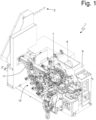
- reference numeral 1 indicates, as a whole, a packer machine which is designed to produce a rigid cigarette pack 2 with a hinged lid and operates with an intermittent motion (i.e. a motion that provides for a cyclical alternation of motion steps and still steps).
- the cigarette pack 2 comprises a cup-shaped outer container made of cardboard or rigid paperboard and a wrap 3 (illustrated in Figure 2 ) containing a group of cigarettes and housed inside the container; in particular, the container is made by folding a blank 4 (illustrated in Figure 2 ) and a collar 5 (illustrated in Figure 2 ) around the wrap 3.
- the packer machine 1 comprises a frame 6 which rests on the ground by means of a plurality of feet (not illustrated) and supports a wrapping line 7 provided with a plurality of movable wrapping devices 8 (rotating conveyors, linear conveyors, pushers, folders). According to what illustrated in Figure 2 , along the wrapping line 7 an insertion station S 1 is arranged in which the blanks 4 are fed one after the other to the wrapping line 7, i.e. get into the wrapping line 7.
- the packer machine 1 comprises at least one actuator 9 which is designed to cause the movable wrapping devices 8 of the wrapping line 7 to move.
- the packer machine 1 comprises one single actuator 9 (normally an electric motor) which alone (through a series of mechanical transmissions) causes all the movable wrapping devices 8 of the wrapping line 7 to move.
- the packer machine 1 comprises a series of actuators 9 that cause all the movable wrapping devices 8 of the wrapping line 7 to move; in this case, there is a main or master actuator 9 (normally an electric motor) that generally moves the main conveyors, and a group of secondary or slave actuators 9 (normally electric motors) which follow the motion of the main or master actuator 9 so as to always be synchronized with the main or master actuator 9.
- a main or master actuator 9 normally an electric motor
- secondary or slave actuators 9 normally electric motors
- the packer machine 1 comprises a feeding unit 10 which feeds the blanks 4 (partially glued and partially folded) one after the other to the insertion station S1 and is provided with a vertical hopper 11 (actually titled with respect to the vertical) which houses a stack of blanks 4.
- the hopper 11 has an upper input mouth in which bundles of blanks 4 are cyclically inserted and a lower output mouth from which single blanks 4 are extractable.
- the feeding unit 10 draws the motion (directly or indirectly) from the actuator 9 and thus the feeding unit 10 operates when also the wrapping line 7 operates and vice versa; in fact, the wrapping line 7 would not be able to operate without continuously receiving the blanks 4 from the feeding unit 10 and the feeding unit 10 cannot operate if the wrapping line 7 is stationary (since the stationary wrapping line 7 is not able to receive the blanks 4 provided by the feeding unit 10).
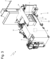
- the packer machine 1 comprises an input station S2 which is separate from the wrapping line 7 and from the feeding unit 10 (thus from the insertion station S 1); in fact, the wrapping line 7 and the feeding unit 10 stand on a front wall of the frame 6, whereas the input station S2 stands on a rear wall of the frame 6.
- the packer machine 1 comprises a transfer unit 12 which is designed to receive groups of blanks 4 (in particular bundles of blanks 4 kept together by respective paper strips or previously deprived of the respective paper strips owing to a manual removal carried out by an operator) in the input station S2 and to release the groups (bundles) of blanks 4 (devoid of the paper strips) in the upper input mouth of the hopper 11; i.e. the transfer unit 12 is designed to receive groups (bundles) of blanks 4 in the input station S2 so as to direct the blanks 4 towards the wrapping line 7 (i.e. towards the insertion station S1).
- the packer machine 1 comprises at least one actuator 13 which is designed to cause the transfer unit 12 (i.e. the various movable components of the transfer unit 12) to move.
- the packer machine 1 comprises one single actuator 13 (normally an electric motor) which alone (through a series of mechanical transmissions) causes all the movable components of the transfer unit 12 to move.
- the packer machine 1 comprises a series of actuators 13 that cause all the movable components of the transfer unit 12 to move; in this case, there is a main or master actuator 13 (normally an electric motor) that generally moves the main conveyors and a group of secondary or slave actuators 13 (normally electric motors) that follow the motion of the main or master actuator 13 so as to always be synchronized with the main or master actuator 13.
- a main or master actuator 13 normally an electric motor
- secondary or slave actuators 13 normally electric motors
- a virtual master reference could be used.
- the packer machine 1 comprises a protection case 14 which encloses the input station S2, i.e. which prevents the direct access from the outside to the input station S2.
- the protection case 14 has a loading opening 15 through which the groups (bundles) of blanks 7 can be manually inserted in the input station S2.
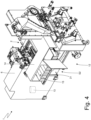
- a sensor device 16 is coupled to the loading opening 15, said sensor device 16 being designed to detect the presence of a body (object) in the loading opening 15 of the input station S2; in particular, the sensor device 16 is designed to detect any kind of body in the loading opening 15 of the input station S2 regardless of whether the body is a group (bundle) of blanks 4 or something else (such as, for example, the hand or the arm of an operator or also an object left by mistake).
- the sensor device 16 only detects the possible presence of a body in the loading opening 15 of the input station S2; alternatively, the sensor device 16 could also be able to recognize the nature of the body present in the loading opening 15 (i.e. recognize whether the body present in the loading opening 15 is a group of blanks 4 or something else).
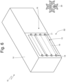
- the loading opening 15 of the input station S2 is devoid of physical doors (i.e. is always open) and the sensor device 16 creates a virtual barrier that is interrupted by a (foreign) body that stands in the loading opening 15 of the input station S2 (i.e. by anybody, object, that stands in the loading opening 15 of the input station S2 when the loading opening 15 should be free, empty); in this case, the sensor device 16 comprises a plurality of emitters 17 and of receivers 18: the emitters emit electromagnetic radiations 19 (generally not visible to the human eye) which are received by the receivers 18 and are screened by a possible body (such electromagnetic radiations 19 create the virtual barrier which is interrupted by a body).
- the loading opening 15 of the input station S2 is normally closed by a physical door (i.e. is normally closed) which constitutes a physical barrier; in this embodiment, the sensor device 16 detects the opening of the door and assumes that a body is (potentially) present in the input station S2 when the door is open.
- the packer machine 1 comprises a control unit 20 which is configured to stop, when the packer machine 1 is working, the actuator 13 of the transfer unit 12, thus allowing the actuator 9 of the wrapping line 7 to normally operate, if the sensor device 16 detects the presence of a body in the loading opening 15 of the input station S2, and to automatically restart the actuator 13 if the sensor device 16 stops detecting the presence of a body in the loading opening 15 of the input station S2.
- the control unit 20 is configured to automatically restart the actuator 13 of the transfer unit 12, if the sensor device 16 stops detecting the presence of a body in the loading opening 15 of the input station S2, from the same identical position the actuator 13 of the transfer unit 12 had when it was stopped.
- the control unit 20 preferably instantly stops the actuator 13; in this manner, it is possible to minimize the distance between the loading opening 15 of the input station S2 and the moving members that stand inside the protection case 14 which encloses the input station S2.
- the control unit 20 does not instantly stop the actuator 13, but stops the actuator 13 in a few seconds (1-3 seconds) so as to prevent leaving the actuator 13 stationary in a position that can make the following automatic restart of the actuator 13 difficult; the wait of a few seconds (1-3 seconds) between the instant when the sensor device 16 detects the presence of a body in the loading opening 15 of the input station S2 and the instant of complete stop of the actuator 13 is in no way hazardous since when entering from the loading opening 15 an operator has to anyway use many seconds before arriving in a zone where there are parts of the transfer unit 12 in quick movement.
- the transfer unit 12 comprises a horizontal conveyor belt 21 that starts in the input station S2 (or possibly also upstream of the input station S2) and is designed to support the bundles of blanks 7 moving (very slowly) the bundles of blanks 7 towards a loading device 22 that retrieves one single bundle of blanks 7 from the conveyor belt 21, eliminates (if still present, i.e. has not been previously removed) the strip that keeps the bundle of blanks 7 united, and thus inserts the bundle of blanks 7 in the upper input mouth of the hopper 11.
- the horizontal conveyor belt 21 can start upstream of the input station S2, i.e.
- control unit 20 is configured to completely stop the transfer unit 12 if the sensor device 16 detects the presence of a body in the loading opening 15 of the input station S2; i.e. if the sensor device 16 detects the presence of a body in the loading opening 15 of the input station S2, all the parts of the transfer unit 12 are stopped.
- the transfer unit 12 comprises an initial part in which the input station S2 is present and is moved by the actuator 13, and a final part in which the loading device 22 is present and is moved by a further actuator 23 (schematically illustrated in Figure 5 ) which is independent of the actuator 13; the control unit 20 could be configured to stop only the actuator 13 of the transfer unit 12, thus allowing the actuator 23 to normally operate, if the sensor device 16 detects the presence of a body in the loading opening 15 of the input station S2.
- control unit 20 could be configured to stop only the actuator 13 of the transfer unit 12, thus allowing the actuator 23 to operate at a reduced speed with respect to normal, if the sensor device 16 detects the presence of a body in the loading opening 15 of the input station S2; or the control unit 20 could be configured to initially stop only the actuator 13 of the transfer unit 12, thus allowing the actuator 23 to operate, if the sensor device 16 detects the presence of a body in the loading opening 15 of the input station S2 and to subsequently also stop the actuator 23 if the sensor device 16 continues to detect the presence of a body in the loading opening 15 of the input station S2 (i.e. if the presence of a body in the loading opening 15 of the input station S2 lasts, for example, for more than 5-10 seconds).
- the movable wrapping devices 8 of the wrapping line 7 are moved by means of the actuator 9 (which directly or indirectly also moves the feeding unit 10); the feeding unit 10 transfers to the wrapping line 7 single blanks 4 to be folded in the insertion station S 1 arranged along the wrapping line 7; the bundles of blanks 4 are received in the input station S2 which is separate from the wrapping line 7; and the transfer unit 12, moved by the actuator 13, cyclically inserts the bundles in the upper input mouth of the hopper 11.
- the sensor device 16 detects the presence of a body in the loading opening 15 of the input station S2; the control unit 20 stops, when the packer machine 1 is working, the sole actuator 13, thus allowing the actuator 9 to normally operate, if the sensor device 16 detects the presence of a body in the loading opening 15 of the input station S2; and the control unit 20 automatically restarts the actuator 13 of the transfer unit 12 if the sensor device 16 stops detecting the presence of a body in the loading opening 15 of the input station S2.
- the embodiment illustrated in the accompanying figures refers to the production of a cigarette pack, but the present invention is also applicable without substantial modifications to the production of any other kind of pack of smoking articles (for example a pack of cigars, a pack of electronic cigarettes of the liquid vaporization type, a cigarette pack of next generation without combustion of the tobacco..
- the above-described packer machine 1 has numerous advantages.
- an operator can manually rest the bundles of blanks 4 on the conveyor belt 21 and through the loading opening 15 of the input station S2 in perfect safety and without having to stop the production of the cigarette packs 1 (i.e. without having to stop the wrapping line 7). It is important to observe that this result is obtained without shifting the loading opening 15 far from the moving parts of the packer machine 1, i.e. without increasing the bulks of the packer machine 1; in fact, this result is obtained thanks to the fact of stopping, during the manual loading of the bundles of blanks 4, only the transfer unit 12 (which is then restarted in a completely automatic manner), thus allowing the wrapping line 7 and the feeding unit 10 to always work.
- the advantages of the above-described packer machine 1 consist in having one single sensor device 16, in having a simple operating logic, and in eliminating the need for tunnels and other elements for distancing the loading opening 15 from the moving parts of the packer machine 1 (thus reducing the bulks and/or maximizing the dimensions of the zone where it is possible to stock a pallet that carries the bundles of blanks 4).
- the above-described packer machine 1 provides, in the area of the loading opening 15 of the bundles of blanks 4, for a barrier (for example immaterial) which if opened (or passed through) interrupts the movement of the hazardous members (belonging to the transfer unit 12) reachable by the operator while carrying out the loading of the bundles of blanks 4; the movements of the transfer unit 12 that are interrupted are not indispensable (in a strictly continuous manner) for the operation of the wrapping line 7 which can anyway continue operating. That is, the movements of the transfer unit 12 that are interrupted are only those relative to the loading in the packer machine 1 of the bundles of blanks 4 and are part of a separate work cycle and much slower than a work cycle of the wrapping line 7.
Landscapes
- Engineering & Computer Science (AREA)
- Mechanical Engineering (AREA)
- Wrapping Of Specific Fragile Articles (AREA)
- Auxiliary Devices For And Details Of Packaging Control (AREA)
- Packages (AREA)
Description
- This Patent Application claims priority from
Italian Patent Application No. 102021000004145 filed on February 23, 2021 - The present invention relates to a packer machine and to a wrapping method for producing a pack.
- The present invention is advantageously applied to the production of a rigid cigarette pack with a hinged lid and containing a group of cigarettes, to which the following disclosure will explicitly refer without thereby losing generality.
- The production of a rigid cigarette pack with a hinged lid provides for folding a metallized wrapping sheet around a group of cigarettes so as to form an inner wrap and thus for folding around the inner wrap a collar and a blank so as to form a rigid outer container. Generally, the metallized wrapping sheet and the collar are separated by means of a transverse cut by corresponding continuous belts unwound by coils while the blank is retrieved from the bottom of a hopper.
- Alongside the packer machine a storage area of materials is defined in which a pallet is arranged supporting a group of bundles of blanks; an operator has to regularly retrieve bundles from the pallet so as to insert the bundles in a suitable material loading opening of the packer machine.
- The loading opening is potentially hazardous because it could enable the hands of the operator to reach moving parts of the packer machine. In order to protect the safety of the operator it has been suggested to close the loading opening with a (at least one) (physical or also virtual) door provided with sensors: when the door is opened, the packer machine is immediately stopped so as to lock all the moving parts; however, this solution entails the stopping of the packer machine every time it is necessary to load new materials with a consequent reduction in the average productivity of the packer machine (measured as number of cigarette packs produced in a relatively long period of time such as for example an eight-hour work shift). Alternatively, in order to protect the safety of the operator it has been suggested to shift the loading opening far from the moving parts of the packer machine (and thus from the material treatment zone) so that the operator can use the loading opening also when the packer machine is in movement; however, this solution remarkably increases the bulks of the packer machine.
-
Patent applications No. DE3827915A1 and No.US2020002034A1 describe a packer machine for producing a cigarette pack and provided with a feeding unit of stacks of blanks. -
Patent application No. EP2325116A1 describes a device for loading stacks of blanks to a packer machine. -
Patent application No. US2011090040A1 describes a safety system for detecting the presence of an undesired object in a safety area and for starting a stop sequence of the machine based on signals received from distance measurement sensors. - The object of the present invention is to provide a packer machine and a wrapping method for producing a pack which are devoid of the above-described drawbacks and at the same time are simple and cost-effective to embody.
- In accordance with the present invention, a packer machine and a wrapping method for producing a pack are provided, according to what claimed in the appended claims.
- The claims describe embodiments of the present invention forming integral part of the present description.
- The present invention will now be described with reference to the accompanying drawings, which illustrate a non-limiting example embodiment thereof, wherein:
-
Figure 1 is a front perspective view and with parts removed for clarity of a packer machine manufactured in accordance with the present invention; -
Figure 2 is a perspective and schematic view of part of the packer machine ofFigure 1 ; -
Figures 3 ,4 and5 are three different rear perspective views and with parts removed for clarity of the packer machine ofFigure 1 ; and -
Figure 6 is a perspective and schematic view of part of the packer machine ofFigure 1 . - In
Figure 1 ,reference numeral 1 indicates, as a whole, a packer machine which is designed to produce arigid cigarette pack 2 with a hinged lid and operates with an intermittent motion (i.e. a motion that provides for a cyclical alternation of motion steps and still steps). - The
cigarette pack 2 comprises a cup-shaped outer container made of cardboard or rigid paperboard and a wrap 3 (illustrated inFigure 2 ) containing a group of cigarettes and housed inside the container; in particular, the container is made by folding a blank 4 (illustrated inFigure 2 ) and a collar 5 (illustrated inFigure 2 ) around thewrap 3. - The
packer machine 1 comprises aframe 6 which rests on the ground by means of a plurality of feet (not illustrated) and supports awrapping line 7 provided with a plurality of movable wrapping devices 8 (rotating conveyors, linear conveyors, pushers, folders...). According to what illustrated inFigure 2 , along thewrapping line 7 aninsertion station S 1 is arranged in which theblanks 4 are fed one after the other to thewrapping line 7, i.e. get into thewrapping line 7. - According to what illustrated in
Figure 1 , thepacker machine 1 comprises at least oneactuator 9 which is designed to cause themovable wrapping devices 8 of thewrapping line 7 to move. According to a possible embodiment, thepacker machine 1 comprises one single actuator 9 (normally an electric motor) which alone (through a series of mechanical transmissions) causes all themovable wrapping devices 8 of thewrapping line 7 to move. Alternatively, thepacker machine 1 comprises a series ofactuators 9 that cause all themovable wrapping devices 8 of thewrapping line 7 to move; in this case, there is a main or master actuator 9 (normally an electric motor) that generally moves the main conveyors, and a group of secondary or slave actuators 9 (normally electric motors) which follow the motion of the main ormaster actuator 9 so as to always be synchronized with the main ormaster actuator 9. - According to what illustrated in
Figure 1 , thepacker machine 1 comprises afeeding unit 10 which feeds the blanks 4 (partially glued and partially folded) one after the other to the insertion station S1 and is provided with a vertical hopper 11 (actually titled with respect to the vertical) which houses a stack ofblanks 4. Thehopper 11 has an upper input mouth in which bundles ofblanks 4 are cyclically inserted and a lower output mouth from whichsingle blanks 4 are extractable. Thefeeding unit 10 draws the motion (directly or indirectly) from theactuator 9 and thus thefeeding unit 10 operates when also thewrapping line 7 operates and vice versa; in fact, thewrapping line 7 would not be able to operate without continuously receiving theblanks 4 from thefeeding unit 10 and thefeeding unit 10 cannot operate if thewrapping line 7 is stationary (since thestationary wrapping line 7 is not able to receive theblanks 4 provided by the feeding unit 10). According to what illustrated inFigures 3-6 , thepacker machine 1 comprises an input station S2 which is separate from thewrapping line 7 and from the feeding unit 10 (thus from the insertion station S 1); in fact, thewrapping line 7 and thefeeding unit 10 stand on a front wall of theframe 6, whereas the input station S2 stands on a rear wall of theframe 6. Furthermore, thepacker machine 1 comprises atransfer unit 12 which is designed to receive groups of blanks 4 (in particular bundles ofblanks 4 kept together by respective paper strips or previously deprived of the respective paper strips owing to a manual removal carried out by an operator) in the input station S2 and to release the groups (bundles) of blanks 4 (devoid of the paper strips) in the upper input mouth of thehopper 11; i.e. thetransfer unit 12 is designed to receive groups (bundles) ofblanks 4 in the input station S2 so as to direct theblanks 4 towards the wrapping line 7 (i.e. towards the insertion station S1). - The
packer machine 1 comprises at least oneactuator 13 which is designed to cause the transfer unit 12 (i.e. the various movable components of the transfer unit 12) to move. According to a possible embodiment, thepacker machine 1 comprises one single actuator 13 (normally an electric motor) which alone (through a series of mechanical transmissions) causes all the movable components of thetransfer unit 12 to move. Alternatively, thepacker machine 1 comprises a series ofactuators 13 that cause all the movable components of thetransfer unit 12 to move; in this case, there is a main or master actuator 13 (normally an electric motor) that generally moves the main conveyors and a group of secondary or slave actuators 13 (normally electric motors) that follow the motion of the main ormaster actuator 13 so as to always be synchronized with the main ormaster actuator 13. As an alternative to a physical master reference (i.e. a physical actuator which is taken as master reference to follow), a virtual master reference could be used. - According to what illustrated in
Figures 3 ,4 and6 , thepacker machine 1 comprises aprotection case 14 which encloses the input station S2, i.e. which prevents the direct access from the outside to the input station S2. Theprotection case 14 has a loading opening 15 through which the groups (bundles) ofblanks 7 can be manually inserted in the input station S2. - A
sensor device 16 is coupled to theloading opening 15, saidsensor device 16 being designed to detect the presence of a body (object) in theloading opening 15 of the input station S2; in particular, thesensor device 16 is designed to detect any kind of body in theloading opening 15 of the input station S2 regardless of whether the body is a group (bundle) ofblanks 4 or something else (such as, for example, the hand or the arm of an operator or also an object left by mistake). According to a preferred embodiment, thesensor device 16 only detects the possible presence of a body in theloading opening 15 of the input station S2; alternatively, thesensor device 16 could also be able to recognize the nature of the body present in the loading opening 15 (i.e. recognize whether the body present in theloading opening 15 is a group ofblanks 4 or something else). - According to a possible embodiment illustrated in the accompanying figures, the
loading opening 15 of the input station S2 is devoid of physical doors (i.e. is always open) and thesensor device 16 creates a virtual barrier that is interrupted by a (foreign) body that stands in theloading opening 15 of the input station S2 (i.e. by anybody, object, that stands in theloading opening 15 of the input station S2 when theloading opening 15 should be free, empty); in this case, thesensor device 16 comprises a plurality ofemitters 17 and of receivers 18: the emitters emit electromagnetic radiations 19 (generally not visible to the human eye) which are received by thereceivers 18 and are screened by a possible body (suchelectromagnetic radiations 19 create the virtual barrier which is interrupted by a body). According to an alternative embodiment, the loading opening 15 of the input station S2 is normally closed by a physical door (i.e. is normally closed) which constitutes a physical barrier; in this embodiment, thesensor device 16 detects the opening of the door and assumes that a body is (potentially) present in the input station S2 when the door is open. - The
packer machine 1 comprises acontrol unit 20 which is configured to stop, when thepacker machine 1 is working, theactuator 13 of thetransfer unit 12, thus allowing theactuator 9 of thewrapping line 7 to normally operate, if thesensor device 16 detects the presence of a body in theloading opening 15 of the input station S2, and to automatically restart theactuator 13 if thesensor device 16 stops detecting the presence of a body in theloading opening 15 of the input station S2. In particular, thecontrol unit 20 is configured to automatically restart theactuator 13 of thetransfer unit 12, if thesensor device 16 stops detecting the presence of a body in theloading opening 15 of the input station S2, from the same identical position theactuator 13 of thetransfer unit 12 had when it was stopped. To such regard, it is important to observe that, if thesensor device 16 detects the presence of a body in theloading opening 15 of the input station S2, thecontrol unit 20 preferably instantly stops theactuator 13; in this manner, it is possible to minimize the distance between theloading opening 15 of the input station S2 and the moving members that stand inside theprotection case 14 which encloses the input station S2. According to an alternative embodiment, if thesensor device 16 detects the presence of a body in theloading opening 15 of the input station S2, thecontrol unit 20 does not instantly stop theactuator 13, but stops theactuator 13 in a few seconds (1-3 seconds) so as to prevent leaving theactuator 13 stationary in a position that can make the following automatic restart of theactuator 13 difficult; the wait of a few seconds (1-3 seconds) between the instant when thesensor device 16 detects the presence of a body in the loading opening 15 of the input station S2 and the instant of complete stop of theactuator 13 is in no way hazardous since when entering from the loading opening 15 an operator has to anyway use many seconds before arriving in a zone where there are parts of thetransfer unit 12 in quick movement. - According to a preferred embodiment illustrated in the accompanying figures, the
transfer unit 12 comprises ahorizontal conveyor belt 21 that starts in the input station S2 (or possibly also upstream of the input station S2) and is designed to support the bundles ofblanks 7 moving (very slowly) the bundles ofblanks 7 towards aloading device 22 that retrieves one single bundle ofblanks 7 from theconveyor belt 21, eliminates (if still present, i.e. has not been previously removed) the strip that keeps the bundle ofblanks 7 united, and thus inserts the bundle ofblanks 7 in the upper input mouth of thehopper 11. In particular, thehorizontal conveyor belt 21 can start upstream of the input station S2, i.e. upstream of theloading opening 15 of the input station S2; in this manner, it is also possible to load groups (bundles) of blanks on theconveyor belt 21 without engaging theloading opening 15 of the input station S2 and thus without causing the temporary stopping of theactuator 13 of thetransfer unit 12. - According to a preferred embodiment, the
control unit 20 is configured to completely stop thetransfer unit 12 if thesensor device 16 detects the presence of a body in theloading opening 15 of the input station S2; i.e. if thesensor device 16 detects the presence of a body in theloading opening 15 of the input station S2, all the parts of thetransfer unit 12 are stopped. - According to an alternative embodiment, the
transfer unit 12 comprises an initial part in which the input station S2 is present and is moved by theactuator 13, and a final part in which theloading device 22 is present and is moved by a further actuator 23 (schematically illustrated inFigure 5 ) which is independent of theactuator 13; thecontrol unit 20 could be configured to stop only theactuator 13 of thetransfer unit 12, thus allowing theactuator 23 to normally operate, if thesensor device 16 detects the presence of a body in theloading opening 15 of the input station S2. In particular, thecontrol unit 20 could be configured to stop only theactuator 13 of thetransfer unit 12, thus allowing theactuator 23 to operate at a reduced speed with respect to normal, if thesensor device 16 detects the presence of a body in theloading opening 15 of the input station S2; or thecontrol unit 20 could be configured to initially stop only theactuator 13 of thetransfer unit 12, thus allowing theactuator 23 to operate, if thesensor device 16 detects the presence of a body in theloading opening 15 of the input station S2 and to subsequently also stop theactuator 23 if thesensor device 16 continues to detect the presence of a body in theloading opening 15 of the input station S2 (i.e. if the presence of a body in theloading opening 15 of the input station S2 lasts, for example, for more than 5-10 seconds). To summarize what described above: themovable wrapping devices 8 of thewrapping line 7 are moved by means of the actuator 9 (which directly or indirectly also moves the feeding unit 10); thefeeding unit 10 transfers to thewrapping line 7single blanks 4 to be folded in theinsertion station S 1 arranged along thewrapping line 7; the bundles ofblanks 4 are received in the input station S2 which is separate from thewrapping line 7; and thetransfer unit 12, moved by theactuator 13, cyclically inserts the bundles in the upper input mouth of thehopper 11. Furthermore, thesensor device 16 detects the presence of a body in theloading opening 15 of the input station S2; thecontrol unit 20 stops, when thepacker machine 1 is working, thesole actuator 13, thus allowing theactuator 9 to normally operate, if thesensor device 16 detects the presence of a body in theloading opening 15 of the input station S2; and thecontrol unit 20 automatically restarts theactuator 13 of thetransfer unit 12 if thesensor device 16 stops detecting the presence of a body in theloading opening 15 of the input station S2. - The embodiment illustrated in the accompanying figures refers to the production of a cigarette pack, but the present invention is also applicable without substantial modifications to the production of any other kind of pack of smoking articles (for example a pack of cigars, a pack of electronic cigarettes of the liquid vaporization type, a cigarette pack of next generation without combustion of the tobacco..
- The above-described
packer machine 1 has numerous advantages. - Firstly, an operator can manually rest the bundles of
blanks 4 on theconveyor belt 21 and through the loading opening 15 of the input station S2 in perfect safety and without having to stop the production of the cigarette packs 1 (i.e. without having to stop the wrapping line 7). It is important to observe that this result is obtained without shifting theloading opening 15 far from the moving parts of thepacker machine 1, i.e. without increasing the bulks of thepacker machine 1; in fact, this result is obtained thanks to the fact of stopping, during the manual loading of the bundles ofblanks 4, only the transfer unit 12 (which is then restarted in a completely automatic manner), thus allowing thewrapping line 7 and thefeeding unit 10 to always work. - In other words, the advantages of the above-described
packer machine 1 consist in having onesingle sensor device 16, in having a simple operating logic, and in eliminating the need for tunnels and other elements for distancing the loading opening 15 from the moving parts of the packer machine 1 (thus reducing the bulks and/or maximizing the dimensions of the zone where it is possible to stock a pallet that carries the bundles of blanks 4). - In fact, the above-described
packer machine 1 provides, in the area of the loading opening 15 of the bundles ofblanks 4, for a barrier (for example immaterial) which if opened (or passed through) interrupts the movement of the hazardous members (belonging to the transfer unit 12) reachable by the operator while carrying out the loading of the bundles ofblanks 4; the movements of thetransfer unit 12 that are interrupted are not indispensable (in a strictly continuous manner) for the operation of thewrapping line 7 which can anyway continue operating. That is, the movements of thetransfer unit 12 that are interrupted are only those relative to the loading in thepacker machine 1 of the bundles ofblanks 4 and are part of a separate work cycle and much slower than a work cycle of thewrapping line 7. The moment when the barrier is closed (or stops being passed through), the movements of thetransfer unit 12 that had been interrupted, immediately and automatically restart, without generating a hazard for the operator who is no longer in the hazardous zone; in restarting the movements, the work cycle that had been interrupted is continued resuming from the same point, without the need to reset or to reactivate movements or motors. In this manner, the cycle restarts and can continue exploiting all the moments in which the operator does not have his/her hands (or other parts of the body) in the zone near the potentially hazardous parts, i.e. in which the operator is not inside the loading opening 15 of the input station S2. - In use, between the loading of one or more bundles of
blanks 4, while the operator momentarily moves away from the loading opening 15 of the input station S2 for retrieving the following bundles ofblanks 4, the loading cycle continues from where it had remained, essentially allowing loading the bundles ofblanks 4 without there being repercussions on the working of thewrapping line 7.
Claims (10)
- A packer machine (1) to produce a pack (2); the packer machine (1) comprises:a protection case (14);a wrapping line (7), which is provided with a plurality of movable wrapping devices (8);at least one first actuator (9), which is designed to cause the movable wrapping devices (8) to move;an insertion station (S 1), which is arranged along the wrapping line (7) and where the wrapping line (7) receives one single wrapping material to be folded;an input station (S2), which is separate from the wrapping line (7) and has a loading opening (15) obtained in the protection case (14);a transfer unit (12), which is designed to receive wrapping material groups in the input station (S2) and to direct the wrapping material towards the wrapping line (7); andat least one second actuator (13), which is independent of the first actuator (9) and is designed to move the transfer unit (12);wherein the protection case (14) encloses the input station (S2), i.e. prevents the direct access from the outside to the input station (S2);the packer machine (1) is characterized in that it comprises:a sensor device (16), which is designed to detect the presence of a body in the loading opening (15) of the input station (S2); anda control unit (20), which is configured to stop, when the packer machine (1) is working, the sole second actuator (13), thus allowing the first actuator (9) to normally operate, if the sensor device (16) detects the presence of a body in the loading opening (15) and to automatically restart the second actuator (13) if the sensor device (16) stops detecting the presence of a body in the loading opening (15).
- The packer machine (1) according to claim 1, wherein the control unit (20) is configured to automatically restart the second actuator (13), if the sensor device (16) stops detecting the presence of a body in the loading opening (15), from the same identical position the second actuator (13) had when it was stopped.
- The packer machine (1) according to claim 1 or 2, wherein the control unit (20) is configured to completely stop the transfer unit (12) if the sensor device (16) detects the presence of a body in the loading opening (15).
- The packer machine (1) according to claim 1, 2 or 3, wherein the sensor device (16) is designed to detect any kind of body in the loading opening (15) regardless of whether the object is a wrapping material group or something else.
- The packer machine (1) according to one of the claims from 1 to 4, wherein the transfer unit (12) comprises a conveyor belt (21), which is designed to feed a series of wrapping material groups and starts in the area of the input station (S2) or upstream of the input station (S2).
- The packer machine (1) according to one of the claims from 1 to 5, wherein the sensor device (16) creates a virtual barrier, which is interrupted by a body standing in the loading opening (15).
- The packer machine (1) according to one of the claims from 1 to 5, wherein:the loading opening (15) is normally closed by a door;the sensor device (16) detects the opening and the closing of the door; andthe control unit (20) is configured to assume that there is a body in the input station (S2) when the door is open.
- The packer machine (1) according to one of the claims from 1 to 7, wherein the wrapping material is a blank (4) and a wrapping material group is a bundle of blanks (4).
- The packer machine (1) according to claim 8, wherein:a feeding unit (10) is provided, which feeds the blanks (4) one after the other to the insertion station (S1) and is provided with a hopper (11), which houses a stack of blanks (4); andthe transfer unit (12) is designed to insert the wrapping material groups into the hopper (11).
- A wrapping method to produce a pack (2); the wrapping method comprises the steps of:causing the movable wrapping devices (8) of a wrapping line (7) to move by means of at least one first actuator (9);transferring to the wrapping line (7) one single wrapping material to be folded in an insertion station (S 1) arranged along the wrapping line (7);receiving, by means of a transfer unit (12), wrapping material groups in an input station (S2), which is separate from the wrapping line (7) and has a loading opening (15) obtained in a protection case (14);directing the wrapping material towards the wrapping line (7) by means of the transfer unit (12); andmoving the transfer unit (12) by means of a second actuator (13), which is independent of the first actuator (9);wherein the protection case (14) encloses the input station (S2), i.e. prevents the direct access from the outside to the input station (S2);the wrapping method is characterized in that it comprises the further steps of:detecting the presence of a body in the loading opening (15) of the input station (S2) by means of at least one sensor device (16);stopping, when the packer machine (1) is working, the sole second actuator (13), thus allowing the first actuator (9) to normally operate, if the sensor device (16) detects the presence of a body in the loading opening (15); andautomatically restarting the second actuator (13) if the sensor device (16) stops detecting the presence of a body in the loading opening (15).
Applications Claiming Priority (1)
| Application Number | Priority Date | Filing Date | Title |
|---|---|---|---|
| IT102021000004145A IT202100004145A1 (en) | 2021-02-23 | 2021-02-23 | PACKAGING MACHINE AND WRAPPING METHOD TO PRODUCE A PACKAGE USING AT LEAST ONE WRAPPING MATERIAL |
Publications (2)
| Publication Number | Publication Date |
|---|---|
| EP4046924A1 EP4046924A1 (en) | 2022-08-24 |
| EP4046924B1 true EP4046924B1 (en) | 2024-12-04 |
Family
ID=75936986
Family Applications (1)
| Application Number | Title | Priority Date | Filing Date |
|---|---|---|---|
| EP22158349.5A Active EP4046924B1 (en) | 2021-02-23 | 2022-02-23 | Packer machine and wrapping method to produce a pack using at least one wrapping material |
Country Status (3)
| Country | Link |
|---|---|
| EP (1) | EP4046924B1 (en) |
| IT (1) | IT202100004145A1 (en) |
| PL (1) | PL4046924T3 (en) |
Family Cites Families (4)
| Publication number | Priority date | Publication date | Assignee | Title |
|---|---|---|---|---|
| DE3827915A1 (en) * | 1988-08-17 | 1990-03-01 | Focke & Co | DEVICE FOR FEEDING (PACKING) CUTTINGS TO A PACKING MACHINE |
| US8446247B2 (en) * | 2009-10-21 | 2013-05-21 | J&L Group International, Llc | Safety system |
| EP2325116A1 (en) * | 2009-11-23 | 2011-05-25 | Verpama AG | Device for loading a processing unit with blanks |
| IT201700025745A1 (en) * | 2017-03-08 | 2018-09-08 | Gd Spa | Method for making a package of smoking articles, a system that implements this method and package obtained by this method. |
-
2021
- 2021-02-23 IT IT102021000004145A patent/IT202100004145A1/en unknown
-
2022
- 2022-02-23 EP EP22158349.5A patent/EP4046924B1/en active Active
- 2022-02-23 PL PL22158349.5T patent/PL4046924T3/en unknown
Also Published As
| Publication number | Publication date |
|---|---|
| EP4046924A1 (en) | 2022-08-24 |
| PL4046924T3 (en) | 2025-03-03 |
| IT202100004145A1 (en) | 2022-08-23 |
Similar Documents
| Publication | Publication Date | Title |
|---|---|---|
| EP1371564B1 (en) | Method and machine for packing a product using a flat tubular package | |
| JP6911041B2 (en) | Machine to form filter bag for extraction products | |
| EP4051595B1 (en) | Grouping unit and method to form a group consisting of two wraps, each containing a group of smoking articles | |
| EP3546377B1 (en) | Packer machine and wrapping method to produce a cigarette pack provided with an outer container and a hinged lid by folding a blank around a wrap enclosing a group of smoking articles. | |
| EP3725690B1 (en) | Wrapping unit and wrapping method to fold a wrapping sheet around a group of smoking articles | |
| EP0949145B1 (en) | Method and machine for packaging of objects, by means of pieces of sheet material obtained from a continuous strip | |
| EP3725691A1 (en) | Packer machine and wrapping method to produce a rigid pack for smoking articles | |
| EP2626305B1 (en) | Packing machine and method for producing rigid packets, each comprising at least two containers one inside the other | |
| WO2012020374A1 (en) | Apparatus and method for feeding stacks of tissues or similar folded products to an automatic packaging system | |
| WO2011039707A1 (en) | Machine for packing infusion products into capsules | |
| EP0751069B1 (en) | Process and device for the fabrication of packages for cylindrical products, particularly cigarettes or similar | |
| EP4046924B1 (en) | Packer machine and wrapping method to produce a pack using at least one wrapping material | |
| KR20130019787A (en) | Paper cup automatic packing apparatus | |
| EP3630620B1 (en) | A method for controlling a packing machine manufacturing packets of smoking articles, each containing two distinct groups of smoking articles | |
| EP1772383A1 (en) | Method and machine for packing a product in at least one sheet of packing material | |
| EP3546378B1 (en) | Packer machine and wrapping method to fold a wrap around a group of smoking articles | |
| EP3546379B1 (en) | Wrapping unit and method for folding a wrap around a group of smoking articles | |
| EP4289752A1 (en) | Packer machine and wrapping method to couple an inner frame to two groups of smoking articles | |
| EP4577457A1 (en) | Packaging machine and method for packaging products | |
| GB1384722A (en) | Methods and apparatus for packing articles | |
| JP3071325B2 (en) | Product filling control method for small box packing machine | |
| JP3083713B2 (en) | Carton packing equipment | |
| EP4574691A1 (en) | Packer machine and wrapping method to produce a pack for smoking articles | |
| EP4667371A1 (en) | Forming unit and method to couple two reinforcement elements to two groups of smoking articles side by side | |
| EP4660088A2 (en) | A wrapping unit and method to produce, together, two sealed wraps containing two corresponding groups of smoking articles |
Legal Events
| Date | Code | Title | Description |
|---|---|---|---|
| PUAI | Public reference made under article 153(3) epc to a published international application that has entered the european phase |
Free format text: ORIGINAL CODE: 0009012 |
|
| STAA | Information on the status of an ep patent application or granted ep patent |
Free format text: STATUS: THE APPLICATION HAS BEEN PUBLISHED |
|
| AK | Designated contracting states |
Kind code of ref document: A1 Designated state(s): AL AT BE BG CH CY CZ DE DK EE ES FI FR GB GR HR HU IE IS IT LI LT LU LV MC MK MT NL NO PL PT RO RS SE SI SK SM TR |
|
| STAA | Information on the status of an ep patent application or granted ep patent |
Free format text: STATUS: REQUEST FOR EXAMINATION WAS MADE |
|
| 17P | Request for examination filed |
Effective date: 20230216 |
|
| RBV | Designated contracting states (corrected) |
Designated state(s): AL AT BE BG CH CY CZ DE DK EE ES FI FR GB GR HR HU IE IS IT LI LT LU LV MC MK MT NL NO PL PT RO RS SE SI SK SM TR |
|
| P01 | Opt-out of the competence of the unified patent court (upc) registered |
Effective date: 20230529 |
|
| GRAP | Despatch of communication of intention to grant a patent |
Free format text: ORIGINAL CODE: EPIDOSNIGR1 |
|
| STAA | Information on the status of an ep patent application or granted ep patent |
Free format text: STATUS: GRANT OF PATENT IS INTENDED |
|
| RIC1 | Information provided on ipc code assigned before grant |
Ipc: B65H 7/14 20060101ALI20240730BHEP Ipc: B65H 5/00 20060101ALI20240730BHEP Ipc: B65H 26/00 20060101ALI20240730BHEP Ipc: B65H 3/08 20060101ALI20240730BHEP Ipc: B65H 1/28 20060101ALI20240730BHEP Ipc: B65H 1/30 20060101ALI20240730BHEP Ipc: B65B 57/04 20060101ALI20240730BHEP Ipc: B65B 57/00 20060101ALI20240730BHEP Ipc: B65B 19/22 20060101ALI20240730BHEP Ipc: B65B 41/06 20060101ALI20240730BHEP Ipc: B65B 43/44 20060101ALI20240730BHEP Ipc: B65B 43/18 20060101AFI20240730BHEP |
|
| INTG | Intention to grant announced |
Effective date: 20240812 |
|
| GRAS | Grant fee paid |
Free format text: ORIGINAL CODE: EPIDOSNIGR3 |
|
| GRAA | (expected) grant |
Free format text: ORIGINAL CODE: 0009210 |
|
| STAA | Information on the status of an ep patent application or granted ep patent |
Free format text: STATUS: THE PATENT HAS BEEN GRANTED |
|
| AK | Designated contracting states |
Kind code of ref document: B1 Designated state(s): AL AT BE BG CH CY CZ DE DK EE ES FI FR GB GR HR HU IE IS IT LI LT LU LV MC MK MT NL NO PL PT RO RS SE SI SK SM TR |
|
| REG | Reference to a national code |
Ref country code: CH Ref legal event code: EP |
|
| REG | Reference to a national code |
Ref country code: DE Ref legal event code: R096 Ref document number: 602022008274 Country of ref document: DE |
|
| REG | Reference to a national code |
Ref country code: IE Ref legal event code: FG4D |
|
| REG | Reference to a national code |
Ref country code: LT Ref legal event code: MG9D |
|
| REG | Reference to a national code |
Ref country code: NL Ref legal event code: MP Effective date: 20241204 |
|
| PG25 | Lapsed in a contracting state [announced via postgrant information from national office to epo] |
Ref country code: HR Free format text: LAPSE BECAUSE OF FAILURE TO SUBMIT A TRANSLATION OF THE DESCRIPTION OR TO PAY THE FEE WITHIN THE PRESCRIBED TIME-LIMIT Effective date: 20241204 |
|
| PGFP | Annual fee paid to national office [announced via postgrant information from national office to epo] |
Ref country code: DE Payment date: 20250227 Year of fee payment: 4 |
|
| PG25 | Lapsed in a contracting state [announced via postgrant information from national office to epo] |
Ref country code: FI Free format text: LAPSE BECAUSE OF FAILURE TO SUBMIT A TRANSLATION OF THE DESCRIPTION OR TO PAY THE FEE WITHIN THE PRESCRIBED TIME-LIMIT Effective date: 20241204 |
|
| PG25 | Lapsed in a contracting state [announced via postgrant information from national office to epo] |
Ref country code: BG Free format text: LAPSE BECAUSE OF FAILURE TO SUBMIT A TRANSLATION OF THE DESCRIPTION OR TO PAY THE FEE WITHIN THE PRESCRIBED TIME-LIMIT Effective date: 20241204 |
|
| PG25 | Lapsed in a contracting state [announced via postgrant information from national office to epo] |
Ref country code: ES Free format text: LAPSE BECAUSE OF FAILURE TO SUBMIT A TRANSLATION OF THE DESCRIPTION OR TO PAY THE FEE WITHIN THE PRESCRIBED TIME-LIMIT Effective date: 20241204 |
|
| PG25 | Lapsed in a contracting state [announced via postgrant information from national office to epo] |
Ref country code: NO Free format text: LAPSE BECAUSE OF FAILURE TO SUBMIT A TRANSLATION OF THE DESCRIPTION OR TO PAY THE FEE WITHIN THE PRESCRIBED TIME-LIMIT Effective date: 20250304 |
|
| PG25 | Lapsed in a contracting state [announced via postgrant information from national office to epo] |
Ref country code: LV Free format text: LAPSE BECAUSE OF FAILURE TO SUBMIT A TRANSLATION OF THE DESCRIPTION OR TO PAY THE FEE WITHIN THE PRESCRIBED TIME-LIMIT Effective date: 20241204 Ref country code: GR Free format text: LAPSE BECAUSE OF FAILURE TO SUBMIT A TRANSLATION OF THE DESCRIPTION OR TO PAY THE FEE WITHIN THE PRESCRIBED TIME-LIMIT Effective date: 20250305 |
|
| PGFP | Annual fee paid to national office [announced via postgrant information from national office to epo] |
Ref country code: PL Payment date: 20250205 Year of fee payment: 4 |
|
| PG25 | Lapsed in a contracting state [announced via postgrant information from national office to epo] |
Ref country code: RS Free format text: LAPSE BECAUSE OF FAILURE TO SUBMIT A TRANSLATION OF THE DESCRIPTION OR TO PAY THE FEE WITHIN THE PRESCRIBED TIME-LIMIT Effective date: 20250304 |
|
| PG25 | Lapsed in a contracting state [announced via postgrant information from national office to epo] |
Ref country code: NL Free format text: LAPSE BECAUSE OF FAILURE TO SUBMIT A TRANSLATION OF THE DESCRIPTION OR TO PAY THE FEE WITHIN THE PRESCRIBED TIME-LIMIT Effective date: 20241204 |
|
| REG | Reference to a national code |
Ref country code: AT Ref legal event code: MK05 Ref document number: 1747953 Country of ref document: AT Kind code of ref document: T Effective date: 20241204 |
|
| PG25 | Lapsed in a contracting state [announced via postgrant information from national office to epo] |
Ref country code: SM Free format text: LAPSE BECAUSE OF FAILURE TO SUBMIT A TRANSLATION OF THE DESCRIPTION OR TO PAY THE FEE WITHIN THE PRESCRIBED TIME-LIMIT Effective date: 20241204 |
|
| PG25 | Lapsed in a contracting state [announced via postgrant information from national office to epo] |
Ref country code: IS Free format text: LAPSE BECAUSE OF FAILURE TO SUBMIT A TRANSLATION OF THE DESCRIPTION OR TO PAY THE FEE WITHIN THE PRESCRIBED TIME-LIMIT Effective date: 20250404 |
|
| PG25 | Lapsed in a contracting state [announced via postgrant information from national office to epo] |
Ref country code: PT Free format text: LAPSE BECAUSE OF FAILURE TO SUBMIT A TRANSLATION OF THE DESCRIPTION OR TO PAY THE FEE WITHIN THE PRESCRIBED TIME-LIMIT Effective date: 20250404 |
|
| PG25 | Lapsed in a contracting state [announced via postgrant information from national office to epo] |
Ref country code: EE Free format text: LAPSE BECAUSE OF FAILURE TO SUBMIT A TRANSLATION OF THE DESCRIPTION OR TO PAY THE FEE WITHIN THE PRESCRIBED TIME-LIMIT Effective date: 20241204 |
|
| PG25 | Lapsed in a contracting state [announced via postgrant information from national office to epo] |
Ref country code: AT Free format text: LAPSE BECAUSE OF FAILURE TO SUBMIT A TRANSLATION OF THE DESCRIPTION OR TO PAY THE FEE WITHIN THE PRESCRIBED TIME-LIMIT Effective date: 20241204 Ref country code: RO Free format text: LAPSE BECAUSE OF FAILURE TO SUBMIT A TRANSLATION OF THE DESCRIPTION OR TO PAY THE FEE WITHIN THE PRESCRIBED TIME-LIMIT Effective date: 20241204 |
|
| PG25 | Lapsed in a contracting state [announced via postgrant information from national office to epo] |
Ref country code: SK Free format text: LAPSE BECAUSE OF FAILURE TO SUBMIT A TRANSLATION OF THE DESCRIPTION OR TO PAY THE FEE WITHIN THE PRESCRIBED TIME-LIMIT Effective date: 20241204 |
|
| PG25 | Lapsed in a contracting state [announced via postgrant information from national office to epo] |
Ref country code: CZ Free format text: LAPSE BECAUSE OF FAILURE TO SUBMIT A TRANSLATION OF THE DESCRIPTION OR TO PAY THE FEE WITHIN THE PRESCRIBED TIME-LIMIT Effective date: 20241204 |
|
| PG25 | Lapsed in a contracting state [announced via postgrant information from national office to epo] |
Ref country code: IT Free format text: LAPSE BECAUSE OF FAILURE TO SUBMIT A TRANSLATION OF THE DESCRIPTION OR TO PAY THE FEE WITHIN THE PRESCRIBED TIME-LIMIT Effective date: 20241204 |
|
| REG | Reference to a national code |
Ref country code: DE Ref legal event code: R026 Ref document number: 602022008274 Country of ref document: DE |
|
| PLBI | Opposition filed |
Free format text: ORIGINAL CODE: 0009260 |
|
| PG25 | Lapsed in a contracting state [announced via postgrant information from national office to epo] |
Ref country code: SE Free format text: LAPSE BECAUSE OF FAILURE TO SUBMIT A TRANSLATION OF THE DESCRIPTION OR TO PAY THE FEE WITHIN THE PRESCRIBED TIME-LIMIT Effective date: 20241204 |
|
| PG25 | Lapsed in a contracting state [announced via postgrant information from national office to epo] |
Ref country code: MC Free format text: LAPSE BECAUSE OF FAILURE TO SUBMIT A TRANSLATION OF THE DESCRIPTION OR TO PAY THE FEE WITHIN THE PRESCRIBED TIME-LIMIT Effective date: 20241204 |
|
| PLAX | Notice of opposition and request to file observation + time limit sent |
Free format text: ORIGINAL CODE: EPIDOSNOBS2 |
|
| REG | Reference to a national code |
Ref country code: CH Ref legal event code: PL |
|
| 26 | Opposition filed |
Opponent name: FOCKE & CO. (GMBH & CO. KG) Effective date: 20250825 |
|
| PG25 | Lapsed in a contracting state [announced via postgrant information from national office to epo] |
Ref country code: DK Free format text: LAPSE BECAUSE OF FAILURE TO SUBMIT A TRANSLATION OF THE DESCRIPTION OR TO PAY THE FEE WITHIN THE PRESCRIBED TIME-LIMIT Effective date: 20241204 |
|
| PG25 | Lapsed in a contracting state [announced via postgrant information from national office to epo] |
Ref country code: LU Free format text: LAPSE BECAUSE OF NON-PAYMENT OF DUE FEES Effective date: 20250223 |
|
| PG25 | Lapsed in a contracting state [announced via postgrant information from national office to epo] |
Ref country code: CH Free format text: LAPSE BECAUSE OF NON-PAYMENT OF DUE FEES Effective date: 20250228 |
|
| REG | Reference to a national code |
Ref country code: BE Ref legal event code: MM Effective date: 20250228 |
|
| PG25 | Lapsed in a contracting state [announced via postgrant information from national office to epo] |
Ref country code: FR Free format text: LAPSE BECAUSE OF NON-PAYMENT OF DUE FEES Effective date: 20250228 |
|
| PG25 | Lapsed in a contracting state [announced via postgrant information from national office to epo] |
Ref country code: BE Free format text: LAPSE BECAUSE OF NON-PAYMENT OF DUE FEES Effective date: 20250228 |
|
| PG25 | Lapsed in a contracting state [announced via postgrant information from national office to epo] |
Ref country code: IE Free format text: LAPSE BECAUSE OF NON-PAYMENT OF DUE FEES Effective date: 20250223 |
|
| PLBB | Reply of patent proprietor to notice(s) of opposition received |
Free format text: ORIGINAL CODE: EPIDOSNOBS3 |