EP4046871A1 - Peripheral functional assembly for motor vehicles - Google Patents
Peripheral functional assembly for motor vehicles Download PDFInfo
- Publication number
- EP4046871A1 EP4046871A1 EP21382124.2A EP21382124A EP4046871A1 EP 4046871 A1 EP4046871 A1 EP 4046871A1 EP 21382124 A EP21382124 A EP 21382124A EP 4046871 A1 EP4046871 A1 EP 4046871A1
- Authority
- EP
- European Patent Office
- Prior art keywords
- assembly
- cover
- base bracket
- shaft
- driving means
- Prior art date
- Legal status (The legal status is an assumption and is not a legal conclusion. Google has not performed a legal analysis and makes no representation as to the accuracy of the status listed.)
- Granted
Links
Images


Classifications
-
- B—PERFORMING OPERATIONS; TRANSPORTING
- B60—VEHICLES IN GENERAL
- B60R—VEHICLES, VEHICLE FITTINGS, OR VEHICLE PARTS, NOT OTHERWISE PROVIDED FOR
- B60R1/00—Optical viewing arrangements; Real-time viewing arrangements for drivers or passengers using optical image capturing systems, e.g. cameras or video systems specially adapted for use in or on vehicles
- B60R1/02—Rear-view mirror arrangements
- B60R1/06—Rear-view mirror arrangements mounted on vehicle exterior
- B60R1/062—Rear-view mirror arrangements mounted on vehicle exterior with remote control for adjusting position
- B60R1/07—Rear-view mirror arrangements mounted on vehicle exterior with remote control for adjusting position by electrically powered actuators
- B60R1/074—Rear-view mirror arrangements mounted on vehicle exterior with remote control for adjusting position by electrically powered actuators for retracting the mirror arrangements to a non-use position alongside the vehicle
-
- B—PERFORMING OPERATIONS; TRANSPORTING
- B60—VEHICLES IN GENERAL
- B60Q—ARRANGEMENT OF SIGNALLING OR LIGHTING DEVICES, THE MOUNTING OR SUPPORTING THEREOF OR CIRCUITS THEREFOR, FOR VEHICLES IN GENERAL
- B60Q1/00—Arrangement of optical signalling or lighting devices, the mounting or supporting thereof or circuits therefor
- B60Q1/02—Arrangement of optical signalling or lighting devices, the mounting or supporting thereof or circuits therefor the devices being primarily intended to illuminate the way ahead or to illuminate other areas of way or environments
- B60Q1/04—Arrangement of optical signalling or lighting devices, the mounting or supporting thereof or circuits therefor the devices being primarily intended to illuminate the way ahead or to illuminate other areas of way or environments the devices being headlights
- B60Q1/06—Arrangement of optical signalling or lighting devices, the mounting or supporting thereof or circuits therefor the devices being primarily intended to illuminate the way ahead or to illuminate other areas of way or environments the devices being headlights adjustable, e.g. remotely-controlled from inside vehicle
- B60Q1/076—Arrangement of optical signalling or lighting devices, the mounting or supporting thereof or circuits therefor the devices being primarily intended to illuminate the way ahead or to illuminate other areas of way or environments the devices being headlights adjustable, e.g. remotely-controlled from inside vehicle by electrical means including means to transmit the movements, e.g. shafts or joints
-
- B—PERFORMING OPERATIONS; TRANSPORTING
- B60—VEHICLES IN GENERAL
- B60Q—ARRANGEMENT OF SIGNALLING OR LIGHTING DEVICES, THE MOUNTING OR SUPPORTING THEREOF OR CIRCUITS THEREFOR, FOR VEHICLES IN GENERAL
- B60Q1/00—Arrangement of optical signalling or lighting devices, the mounting or supporting thereof or circuits therefor
- B60Q1/26—Arrangement of optical signalling or lighting devices, the mounting or supporting thereof or circuits therefor the devices being primarily intended to indicate the vehicle, or parts thereof, or to give signals, to other traffic
- B60Q1/2692—Arrangement of optical signalling or lighting devices, the mounting or supporting thereof or circuits therefor the devices being primarily intended to indicate the vehicle, or parts thereof, or to give signals, to other traffic retractable lights
-
- B—PERFORMING OPERATIONS; TRANSPORTING
- B60—VEHICLES IN GENERAL
- B60Q—ARRANGEMENT OF SIGNALLING OR LIGHTING DEVICES, THE MOUNTING OR SUPPORTING THEREOF OR CIRCUITS THEREFOR, FOR VEHICLES IN GENERAL
- B60Q1/00—Arrangement of optical signalling or lighting devices, the mounting or supporting thereof or circuits therefor
- B60Q1/26—Arrangement of optical signalling or lighting devices, the mounting or supporting thereof or circuits therefor the devices being primarily intended to indicate the vehicle, or parts thereof, or to give signals, to other traffic
- B60Q1/46—Arrangement of optical signalling or lighting devices, the mounting or supporting thereof or circuits therefor the devices being primarily intended to indicate the vehicle, or parts thereof, or to give signals, to other traffic for giving flashing caution signals during drive, other than signalling change of direction, e.g. flashing the headlights or hazard lights
-
- B—PERFORMING OPERATIONS; TRANSPORTING
- B60—VEHICLES IN GENERAL
- B60R—VEHICLES, VEHICLE FITTINGS, OR VEHICLE PARTS, NOT OTHERWISE PROVIDED FOR
- B60R11/00—Arrangements for holding or mounting articles, not otherwise provided for
-
- B—PERFORMING OPERATIONS; TRANSPORTING
- B60—VEHICLES IN GENERAL
- B60R—VEHICLES, VEHICLE FITTINGS, OR VEHICLE PARTS, NOT OTHERWISE PROVIDED FOR
- B60R11/00—Arrangements for holding or mounting articles, not otherwise provided for
- B60R11/04—Mounting of cameras operative during drive; Arrangement of controls thereof relative to the vehicle
-
- F—MECHANICAL ENGINEERING; LIGHTING; HEATING; WEAPONS; BLASTING
- F16—ENGINEERING ELEMENTS AND UNITS; GENERAL MEASURES FOR PRODUCING AND MAINTAINING EFFECTIVE FUNCTIONING OF MACHINES OR INSTALLATIONS; THERMAL INSULATION IN GENERAL
- F16M—FRAMES, CASINGS OR BEDS OF ENGINES, MACHINES OR APPARATUS, NOT SPECIFIC TO ENGINES, MACHINES OR APPARATUS PROVIDED FOR ELSEWHERE; STANDS; SUPPORTS
- F16M11/00—Stands or trestles as supports for apparatus or articles placed thereon ; Stands for scientific apparatus such as gravitational force meters
- F16M11/02—Heads
- F16M11/04—Means for attachment of apparatus; Means allowing adjustment of the apparatus relatively to the stand
- F16M11/06—Means for attachment of apparatus; Means allowing adjustment of the apparatus relatively to the stand allowing pivoting
- F16M11/08—Means for attachment of apparatus; Means allowing adjustment of the apparatus relatively to the stand allowing pivoting around a vertical axis, e.g. panoramic heads
-
- F—MECHANICAL ENGINEERING; LIGHTING; HEATING; WEAPONS; BLASTING
- F16—ENGINEERING ELEMENTS AND UNITS; GENERAL MEASURES FOR PRODUCING AND MAINTAINING EFFECTIVE FUNCTIONING OF MACHINES OR INSTALLATIONS; THERMAL INSULATION IN GENERAL
- F16M—FRAMES, CASINGS OR BEDS OF ENGINES, MACHINES OR APPARATUS, NOT SPECIFIC TO ENGINES, MACHINES OR APPARATUS PROVIDED FOR ELSEWHERE; STANDS; SUPPORTS
- F16M13/00—Other supports for positioning apparatus or articles; Means for steadying hand-held apparatus or articles
- F16M13/02—Other supports for positioning apparatus or articles; Means for steadying hand-held apparatus or articles for supporting on, or attaching to, an object, e.g. tree, gate, window-frame, cycle
-
- B—PERFORMING OPERATIONS; TRANSPORTING
- B60—VEHICLES IN GENERAL
- B60R—VEHICLES, VEHICLE FITTINGS, OR VEHICLE PARTS, NOT OTHERWISE PROVIDED FOR
- B60R11/00—Arrangements for holding or mounting articles, not otherwise provided for
- B60R2011/0001—Arrangements for holding or mounting articles, not otherwise provided for characterised by position
- B60R2011/004—Arrangements for holding or mounting articles, not otherwise provided for characterised by position outside the vehicle
-
- B—PERFORMING OPERATIONS; TRANSPORTING
- B60—VEHICLES IN GENERAL
- B60R—VEHICLES, VEHICLE FITTINGS, OR VEHICLE PARTS, NOT OTHERWISE PROVIDED FOR
- B60R11/00—Arrangements for holding or mounting articles, not otherwise provided for
- B60R2011/0042—Arrangements for holding or mounting articles, not otherwise provided for characterised by mounting means
- B60R2011/008—Adjustable or movable supports
- B60R2011/0082—Adjustable or movable supports collapsible, e.g. for storing after use
-
- B—PERFORMING OPERATIONS; TRANSPORTING
- B60—VEHICLES IN GENERAL
- B60R—VEHICLES, VEHICLE FITTINGS, OR VEHICLE PARTS, NOT OTHERWISE PROVIDED FOR
- B60R11/00—Arrangements for holding or mounting articles, not otherwise provided for
- B60R2011/0042—Arrangements for holding or mounting articles, not otherwise provided for characterised by mounting means
- B60R2011/008—Adjustable or movable supports
- B60R2011/0092—Adjustable or movable supports with motorization
-
- B—PERFORMING OPERATIONS; TRANSPORTING
- B60—VEHICLES IN GENERAL
- B60R—VEHICLES, VEHICLE FITTINGS, OR VEHICLE PARTS, NOT OTHERWISE PROVIDED FOR
- B60R11/00—Arrangements for holding or mounting articles, not otherwise provided for
- B60R2011/0094—Arrangements for holding or mounting articles, not otherwise provided for characterised by means for covering after user, e.g. boxes, shutters or the like
Definitions
- the present disclosure relates in general to peripheral functional assemblies such as winglets intended to be used with electronic or optical devices such as mirrors, lenses, lights, radars, cameras, etc. in motor vehicles.
- Vehicle peripheral functional assemblies are typically mounted outside a motor vehicle for example to allow the driver to see or monitor the outside of the vehicle while driving.
- Peripheral functional assemblies such as for example winglets, rear-view mirrors, etc. are provided with an actuator that includes driving means.
- the driving means usually include an electric motor that is arranged within a housing and are intended for driving the functional assembly in rotation around a fixed part of a motor vehicle between, for example, non-driving and driving positions, relative to the motor vehicle. In a non-driving position, the peripheral functional assembly is folded inwards when the vehicle is parked for protection purposes.
- EP3663135 discloses a retractable viewing device including a base, a shaft and a viewing assembly rotatably attached to the shaft.
- the viewing assembly includes an upper housing and a lower housing, a viewing unit such as a camera, and an electric retracting unit having a casing, a motor arranged in the casing, and a transmission.
- the lower housing of the viewing assembly is recessed to be fitted to the base and is configured to attach the camera.
- the present peripheral functional assembly for motor vehicles comprises a base bracket to be fixedly attached to a motor vehicle and an electric actuator assembly that is pivotally mounted to the base bracket.
- the electric actuator assembly comprises driving means for pivoting to the base bracket.
- the driving means are thus intended for driving the electric actuator assembly in rotation relative to the base bracket that is attached to a motor vehicle.
- the driving means are preferably motor driven, may other types of means for pivoting the actuator assembly to the base bracket are possible, even manually operated.
- the electric actuator assembly of the present peripheral functional assembly further comprises a cover assembly.
- the cover assembly is arranged enclosing the driving means immediately adjacent said driving means.
- the cover assembly is also configured for supporting a functional element.
- a functional element refers to any element intended for performing a specific function, such as an electrical device, for example, a mirror, a video camera, a photo camera, a light, a blinker, a radar, a LIDAR, and so forth.
- the arrangement of the cover assembly immediately adjacent the driving means should be understood as the cover assembly being adjoining at least one part of the driving means, that is, with said elements being next arranged close or next to one another.
- the cover assembly is thus arranged contiguous, near or directly adjacent to the driving means, for example sharing a common border, wall or boundary.
- immediately adjacent does not necessarily involve direct contact between the parts.
- the cover assembly is configured for enclosing the driving means, i.e. for integrating the electric actuator assembly therein, and, at the same time, for supporting a functional element such as an electrical device, for example, a mirror, a camera, a radar, a LIDAR, etc.
- the functional element may be arranged at least partially covered by or supported on the cover assembly.
- the functional element may be arranged resting on the cover assembly.
- Other examples are envisaged for integration of the functional element with the cover assembly.
- the cover assembly may comprise at least a first cover, and a second cover. At least one of the first cover or the second cover is intended to receive the functional element supported therewith. At least one of the first cover or the second cover is stiffer than the other cover. Preferably, the cover intended to support the functional element is stiffer than the other cover.
- the cover assembly may be provided with an extension where the functional element is supported.
- Said extension may be integrally formed with at least one of the first cover or the second cover or it may be removably formed with at least one of the first cover or the second cover.
- the extension may be configured for performing the function of receiving the functional element, without enclosing the driving means.
- the first cover is at least 30% longer than the second cover, even more than 40%. However, there might be cases where the first cover is 10-20% longer than the second cover. In any case, the first cover may protrude in a driving position from the second cover away from the vehicle, transversely to a direction of travel.
- At least one of the first cover or the second cover may be countershaped to at least one portion of the driving means.
- the base bracket is associated with a shaft.
- the shaft may be fixed to or be made integral with the base bracket.
- the shaft may be divided into at least two sections one of which may be made integral with the base bracket.
- the shaft may have a hollow end positioned distal to the base bracket.
- At least one of the first cover or the second cover may surround the shaft externally or be internally arranged thereto. When the shaft is surrounded externally the shaft may protrude over the first or second cover.
- the at least one of the first or the second cover may have a downward projection for surrounding the shaft externally or arranged internally thereto arranged overlapping the shaft. This downward projection allows the electrical actuator to move along the shaft and serves as a guide during that movement.
- the length of the downward projection that overlaps the shaft is more than 2 mm, preferably more than 3 mm and optimally more than 5 mm.
- the base bracket is attached to the shaft and the first cover is coupled to the second cover.
- the shaft as stated above, includes at least two sections, they may be attached to each other through a screw.
- Other alternative attaching means for attaching the shaft sections are possible such as a rivet, glue, welding, etc.
- the assembly process can be advantageously automated avoiding handling a lot of pieces during the final assembly of the peripheral function assembly or the vehicle.
- one section of the shaft is arranged within the cover assembly together with the driving means.
- the actuator assembly with the cover assembly and the driving means can be thus assembled together with one shaft section and coupled to the base bracket.
- the present peripheral functional assembly may further include a plug for covering the hollow end of the base bracket shaft or the downward projection arranged internally to the base bracket shaft.
- the plug is intended to prevent dust and moisture from entering the assembly.
- the plug may be provided with a fastener for fixing cables over the shaft for ensuring that the cables passing through the center of the shaft are held properly in position.
- a series of ramps are associated with or be fixedly attached to the upper surface of the base bracket. No relative movement between the ramps and the base bracket and between the shaft and the base bracket exists. Said ramps may be attached to the upper surface of the base bracket or formed integrally therein. Said ramps associated with the upper surface of the base bracket are arranged such that, in use, interact with a series of ramps formed in a lower surface of the cover assembly and/or with further ramps formed in the driving means. The ramps allow the actuator to be moved along the shaft while rotating around the shaft.
- a small structural volume, simple structure is achieved with the cover assembly described above, since the cover assembly acts as functional element integrator without any accessory parts. No extra frame parts are required for supporting the functional element on the peripheral function assembly. As a result, a cost effective assembly is achieved.
- peripheral functional assembly 100 Examples of a peripheral functional assembly 100 will be described in the following according to the figures 1-8 of the drawings.
- the peripheral functional assembly 100 that is described herein comprises a base bracket 110.
- the base bracket 110 is fixedly attached to a motor vehicle, not shown.
- the peripheral functional assembly 100 further comprises an electric actuator assembly 120 that is pivotally mounted to the base bracket 110 through a shaft 115 that is fixedly attached to the base bracket 110.
- the electric actuator assembly 120 comprises driving means 130 for causing the actuator assembly 120 itself to pivot relative to the base bracket 110 around said shaft 115.
- the driving means 130 are enclosed within a cover assembly 140.
- the cover assembly 140 is arranged immediately adjacent the driving means 130, that is, adjoining at least one of a motor 135 or a transmission 136 of the driving means 130.
- the actuator assembly 120 can be moved along an axis z as shown in figure 1 through ramps 118, 119 which will be described further below in connection with figures 4 , 7, 8 of the drawings. Such movement of the actuator assembly 120 along an axis z is controlled by a spring 138 and is locked by a lock washer 137 shown in figure 1 .
- the actuator assembly 120 can be also rotated around the above mentioned shaft 115 which will be also described further below.
- the cover assembly 140 in addition of performing the function of housing, receiving, and enclosing the driving means 130 including the motor 135 and the transmission 136, it is also configured for supporting a functional element 200.
- the functional element 200 may be, for example, a mirror, an electrical device, such as a video camera, a photo camera, a light, a blinker, a radar, a LIDAR, etc, and in general any element intended for performing a specific function.
- the cover assembly 140 thus integrates the electric actuator assembly 120 therein and also the functional element 200.
- the functional element 200 is supported on the cover assembly 140.
- the cover assembly 140 comprises a first cover or upper cover, also referred herein to as housing bracket 150, and a second cover or lower cover 160.
- the housing bracket 150 is intended to receive the functional element 200 supported therewith.
- the housing bracket 150 is stiffer than the lower cover 160. Examples of ways for stiffening the housing bracket 150 may be providing stiffening elements such as ribs, ridges, etc.; increasing the thickness of the housing bracket 150 with respect to the lower cover, or selecting stiffer materials such as a metal, for example aluminium, magnesium or Zamak alloys, or a reinforced plastic material.
- the spring 138 is arranged to bias the lower cover 160 to the base bracket 110.
- the housing bracket 150 of the cover assembly has an extension 155 formed integrally therewith in the example shown.
- One free end of the extension 155 of the housing bracket 150 is adapted to support the functional element 200.
- the resulting configuration is such that the housing bracket 150 protrudes from the lower cover 160 away from the vehicle in a driving position, in a direction y depicted in figure 1 , transversely to a direction of travel, opposite to direction x depicted in figure 1 .
- the housing bracket 150 is at least 30% longer than the lower cover 160, as illustrated in the figures of the drawings.
- the housing bracket 150 is countershaped to the driving means 130 for example countershaped to at least one of the motor 135 or the transmission 136.
- a shaft 115 is associated with base bracket 110.
- the shaft 115 is divided into a first shaft section 115a and a second shaft section 115b, wherein the first shaft section 115a is the part attached to the base bracket 110, in the example integral to the base bracket 110.
- the shaft 115 has a single shaft section, in the example the single shaft section is made integral with the base bracket 110.
- the first shaft section 115a is attached to the base bracket 110.
- the first shaft section 115a is also attached to the second shaft section 115b that in use is inserted into a cavity 116b formed therein.
- the second shaft section 115b has a recess 116a that is formed in a distal end thereof.
- the recess 116a is intended for receiving therein a plug 170, which will be described further below.
- the base bracket 110 has a projection 156 arranged surrounding the shaft 115 externally or being arranged internally thereto.
- the projection 156 is arranged internally in the recess 116a. This projection 156 helps in guiding the electric actuator assembly 120 as it is displaced axially along the shaft 115 according to axis z shown in figure 1 .
- plug 170 is provided for covering said cavity 116a that is formed in a hollow end 116 of the shaft 115 fixedly attached to the base bracket 110 in order to protect the assembly 100 from dust and moisture.
- the plug 170 may also be placed within the projection 156 when the projection 156 arranged internally the recess 116a of the shaft 115.
- the plug 170 is provided with a fastener 180 for fixing cables over a central part of the shaft 115. This avoids cables to be stretched or shrunk as the electric actuator assembly 120 is pivoted to the base bracket 110 during operation.
- the base bracket 110 has an upper surface 117 with a series of ramps 118 formed thereon.
- the ramps 118 are arranged such that, in use, interact with a series of ramps 119 formed in a lower surface of the cover assembly 140 as shown in figures 4 , 7, 8 of the drawings and/or with other series or ramps formed in the driving means 130.
- the first shaft section 115a is made integral with the base bracket 110 and the second shaft section 115b is attached to the first shaft section 115a through a screw 112.
- the first shaft section 115a is inserted into the second shaft section 115b. This results in a stiffer shaft 115.
- a top cover cap 190 and a bottom cover cap 195 are provided for receiving therein the peripheral functional assembly 100 as shown in figure 1 .
Landscapes
- Engineering & Computer Science (AREA)
- Mechanical Engineering (AREA)
- General Engineering & Computer Science (AREA)
- Multimedia (AREA)
- Motor Or Generator Frames (AREA)
Abstract
Description
- The present disclosure relates in general to peripheral functional assemblies such as winglets intended to be used with electronic or optical devices such as mirrors, lenses, lights, radars, cameras, etc. in motor vehicles.
- Vehicle peripheral functional assemblies are typically mounted outside a motor vehicle for example to allow the driver to see or monitor the outside of the vehicle while driving. Peripheral functional assemblies, such as for example winglets, rear-view mirrors, etc. are provided with an actuator that includes driving means. The driving means usually include an electric motor that is arranged within a housing and are intended for driving the functional assembly in rotation around a fixed part of a motor vehicle between, for example, non-driving and driving positions, relative to the motor vehicle. In a non-driving position, the peripheral functional assembly is folded inwards when the vehicle is parked for protection purposes.
-
EP3663135 discloses a retractable viewing device including a base, a shaft and a viewing assembly rotatably attached to the shaft. The viewing assembly includes an upper housing and a lower housing, a viewing unit such as a camera, and an electric retracting unit having a casing, a motor arranged in the casing, and a transmission. The lower housing of the viewing assembly is recessed to be fitted to the base and is configured to attach the camera. - Known prior art peripheral functional assemblies have been shown to be complex and costly. A need still exists for an improved peripheral functional assembly which at least partially overcomes the above issues.
- The above disadvantages are overcome by the present peripheral functional assembly for vehicles with which important benefits are also obtained.
- The present peripheral functional assembly for motor vehicles comprises a base bracket to be fixedly attached to a motor vehicle and an electric actuator assembly that is pivotally mounted to the base bracket. The electric actuator assembly comprises driving means for pivoting to the base bracket. The driving means are thus intended for driving the electric actuator assembly in rotation relative to the base bracket that is attached to a motor vehicle. Although the driving means are preferably motor driven, may other types of means for pivoting the actuator assembly to the base bracket are possible, even manually operated.
- The electric actuator assembly of the present peripheral functional assembly further comprises a cover assembly. The cover assembly is arranged enclosing the driving means immediately adjacent said driving means. In addition, the cover assembly is also configured for supporting a functional element.
- Within the meaning of the present disclosure, a functional element refers to any element intended for performing a specific function, such as an electrical device, for example, a mirror, a video camera, a photo camera, a light, a blinker, a radar, a LIDAR, and so forth.
- Also within the meaning of the present disclosure, the arrangement of the cover assembly immediately adjacent the driving means should be understood as the cover assembly being adjoining at least one part of the driving means, that is, with said elements being next arranged close or next to one another. The cover assembly is thus arranged contiguous, near or directly adjacent to the driving means, for example sharing a common border, wall or boundary. However, it is to be understood that immediately adjacent does not necessarily involve direct contact between the parts.
- According to the configuration described above, the cover assembly is configured for enclosing the driving means, i.e. for integrating the electric actuator assembly therein, and, at the same time, for supporting a functional element such as an electrical device, for example, a mirror, a camera, a radar, a LIDAR, etc.
- The functional element may be arranged at least partially covered by or supported on the cover assembly. The functional element may be arranged resting on the cover assembly. Other examples are envisaged for integration of the functional element with the cover assembly.
- The cover assembly may comprise at least a first cover, and a second cover. At least one of the first cover or the second cover is intended to receive the functional element supported therewith. At least one of the first cover or the second cover is stiffer than the other cover. Preferably, the cover intended to support the functional element is stiffer than the other cover.
- The cover assembly may be provided with an extension where the functional element is supported. Said extension may be integrally formed with at least one of the first cover or the second cover or it may be removably formed with at least one of the first cover or the second cover.
- The extension may be configured for performing the function of receiving the functional element, without enclosing the driving means.
- It is preferred that the first cover is at least 30% longer than the second cover, even more than 40%. However, there might be cases where the first cover is 10-20% longer than the second cover. In any case, the first cover may protrude in a driving position from the second cover away from the vehicle, transversely to a direction of travel.
- At least one of the first cover or the second cover may be countershaped to at least one portion of the driving means.
- The base bracket is associated with a shaft. The shaft may be fixed to or be made integral with the base bracket. In some examples, the shaft may be divided into at least two sections one of which may be made integral with the base bracket. The shaft may have a hollow end positioned distal to the base bracket. At least one of the first cover or the second cover may surround the shaft externally or be internally arranged thereto. When the shaft is surrounded externally the shaft may protrude over the first or second cover. The at least one of the first or the second cover may have a downward projection for surrounding the shaft externally or arranged internally thereto arranged overlapping the shaft. This downward projection allows the electrical actuator to move along the shaft and serves as a guide during that movement. The length of the downward projection that overlaps the shaft is more than 2 mm, preferably more than 3 mm and optimally more than 5 mm.
- The base bracket is attached to the shaft and the first cover is coupled to the second cover.
- In the event that the shaft, as stated above, includes at least two sections, they may be attached to each other through a screw. Other alternative attaching means for attaching the shaft sections are possible such as a rivet, glue, welding, etc.
- With the shaft comprising at least two sections, the assembly process can be advantageously automated avoiding handling a lot of pieces during the final assembly of the peripheral function assembly or the vehicle. In use, one section of the shaft is arranged within the cover assembly together with the driving means. The actuator assembly with the cover assembly and the driving means can be thus assembled together with one shaft section and coupled to the base bracket.
- The present peripheral functional assembly may further include a plug for covering the hollow end of the base bracket shaft or the downward projection arranged internally to the base bracket shaft. The plug is intended to prevent dust and moisture from entering the assembly. The plug may be provided with a fastener for fixing cables over the shaft for ensuring that the cables passing through the center of the shaft are held properly in position.
- A series of ramps are associated with or be fixedly attached to the upper surface of the base bracket. No relative movement between the ramps and the base bracket and between the shaft and the base bracket exists. Said ramps may be attached to the upper surface of the base bracket or formed integrally therein. Said ramps associated with the upper surface of the base bracket are arranged such that, in use, interact with a series of ramps formed in a lower surface of the cover assembly and/or with further ramps formed in the driving means. The ramps allow the actuator to be moved along the shaft while rotating around the shaft.
- Some aspects, embodiments, or examples of the present peripheral functional assembly are set forth in the following clauses.
- 1. Peripheral functional assembly for motor vehicles, the peripheral functional assembly comprising a base bracket to be fixedly attached to a motor vehicle; and an electric actuator assembly pivotally mounted to the base bracket, the electric actuator assembly comprising driving means for pivoting to the base bracket and a cover assembly; wherein the cover assembly is arranged enclosing the driving means immediately adjacent said driving means, and wherein the cover assembly is arranged to surround externally a shaft associated with the base bracket or be received therein.
- 2. The assembly of clause 1, wherein the cover assembly has a projection arranged to surround externally the shaft associated with the base bracket or be received therein.
- 3. The assembly of clause 1 or 2, wherein the cover assembly comprises at least a first cover and a second cover.
- 4. The assembly of any of the preceding clauses, wherein the cover assembly also supports a functional element.
- 5. The assembly of any of the preceding clauses, wherein the cover assembly has an extension for supporting the functional element.
- 6. The assembly of any of clauses 3-5, wherein the first cover is at least 30% longer than the second cover.
- 7. The assembly of any of clauses 3-6, wherein at least one of the first cover or the second cover is countershaped to at least one portion of the driving means.
- 8. The assembly of any of clauses 2-7, wherein it further includes a plug for covering a hollow end of the base bracket shaft or the projection arranged internally to the base bracket shaft.
- 9. The assembly of clause 8, wherein the plug has a fastener for fixing cables passing over the base bracket shaft.
- 10. The assembly of any of clauses 1-9, wherein the base bracket shaft is divided into at least two sections.
- 11. The assembly of any of the preceding clauses, wherein the shaft is made integral with the base bracket.
- 12. The assembly of any of the preceding clauses, wherein it comprises a series of ramps formed in an upper surface of the base bracket which in use interact with a series of ramps formed in a lower surface of the cover assembly.
- 13. The assembly (100) of any of clauses 3-12, wherein at least one of the first cover or the second cover is stiffer than the other cover.
- 14. The assembly (100) of any of clauses 2-13, wherein the projection overlaps the shaft.
- 15. The assembly (100) of clause 14, wherein the length of the projection that overlaps the shaft is more than 2 mm.
- Still further aspects, embodiments, or examples of the present peripheral functional assembly are set forth in the following clauses.
- 1. Peripheral functional assembly for motor vehicles, the peripheral functional assembly comprising a base bracket to be fixedly attached to a motor vehicle; and an electric actuator assembly pivotally mounted to the base bracket, the electric actuator assembly comprising driving means for pivoting to the base bracket and a cover assembly; wherein the cover assembly is arranged enclosing the driving means immediately adjacent said driving means, and wherein it further includes a plug for covering the hollow end of the base bracket shaft.
- 2. The assembly of clause 1, wherein the plug has a fastener for fixing cables passing over the base bracket.
- 3. The assembly of clause 1 or 2, wherein the cover assembly comprises at least a first cover and a second cover.
- 4. The assembly of any of the preceding clauses, wherein the cover assembly also supports a functional element.
- 5. The assembly of any of the preceding clauses, wherein the cover assembly has an extension where the functional element is supported on or integrally formed with or removably formed with.
- 6. The assembly of any of clauses 3-5, wherein the first cover is at least 30% longer than the second cover.
- 7. The assembly of any of clauses 3-6, wherein at least one of the first cover or the second cover is countershaped to at least one portion of the driving means.
- 8. The assembly of any of the clauses 1-7, wherein the base bracket shaft is divided into at least two sections.
- 9. The assembly of any of the preceding clauses, wherein the shaft is made integral with the base bracket.
- 10. The assembly of any of the preceding clauses, wherein it comprises a series of ramps formed in an upper surface of the base bracket which in use interact with a series of ramps formed in a lower surface of the cover assembly.
- 11. The assembly (100) of any of clauses 3-10, wherein the first cover has a higher stiffness than the second cover.
- 12. The assembly (100) of any clauses 2-10, wherein the fastener ensures that the cables passing through the center of the shaft are held properly in position.
- Other aspects, embodiments, or examples of the present peripheral functional assembly are also set forth in the following clauses.
- 1. Peripheral functional assembly for motor vehicles, the peripheral functional assembly comprising a base bracket to be fixedly attached to a motor vehicle; and an electric actuator assembly pivotally mounted to the base bracket, the electric actuator assembly comprising driving means for pivoting to the base bracket and a cover assembly; wherein the cover assembly is arranged enclosing the driving means immediately adjacent said driving means, and wherein a shaft is associated with the base bracket comprising at least two sections arranged to be inserted into one another.
- 2. The assembly of clause 1, wherein the shaft is made integral with the base bracket.
- 3. The assembly of clause 1 or 2, wherein the cover assembly comprises at least a first cover and a second cover.
- 4. The assembly of any of the preceding clauses, wherein a functional element is supported on or integrally formed with or removably formed with the cover assembly.
- 5. The assembly of any of the preceding, wherein the cover assembly has an extension for supporting the functional element.
- 6. The assembly of any of clauses 3-5, wherein the first cover is at least 30% longer than the second cover.
- 7. The assembly of any of clauses 3-6, wherein at least one of the first cover or the second cover is countershaped to at least one portion of the driving means.
- 8. The assembly of any preceding claims, wherein the cover assembly has a projection arranged to surround externally the shaft associated with the base bracket or be received therein.
- 9. The assembly of clause 8, wherein it further includes a plug for covering a hollow end of the base bracket shaft or the projection arranged internally to the base bracket shaft.
- 10. The assembly of clause 9, wherein the plug has a fastener for fixing cables passing over the base bracket shaft.
- 11. The assembly of any of the preceding clauses, wherein it comprises a series of ramps formed in an upper surface of the base bracket which in use interact with a series of ramps formed in a lower surface of the cover assembly.
- 12. The assembly (100) of any of clauses 3-11, wherein at least one of the first cover or the second cover is stiffer than the other cover.
- Still further aspects, embodiments, or examples of the present peripheral functional assembly are set forth in the following clauses.
- 1. Peripheral functional assembly for motor vehicles, the peripheral functional assembly comprising a base bracket to be fixedly attached to a motor vehicle; and an electric actuator assembly pivotally mounted to the base bracket, the electric actuator assembly comprising driving means for pivoting to the base bracket and a cover assembly; wherein the cover assembly is arranged enclosing the driving means immediately adjacent said driving means, and wherein a shaft is associated the base bracket comprising at least two sections at least one of which sections is made integral with the base bracket.
- 2. The assembly of clause 1, wherein the at least two sections are arranged to be inserted into one another.
- 3. The assembly of clause 1 or 2, wherein the cover assembly comprises at least a first cover and a second cover.
- 4. The assembly of any of the preceding clauses, wherein a functional element is supported on or integrally formed with or removably formed with the cover assembly.
- 5. The assembly of any of the preceding, wherein the cover assembly has an extension for supporting the functional element.
- 6. The assembly of any of clauses 3-5, wherein the first cover is at least 30% longer than the second cover.
- 7. The assembly of any of clauses 3-6, wherein at least one of the first cover or the second cover is countershaped to at least one portion of the driving means.
- 8. The assembly of any preceding claims, wherein the cover assembly has a projection arranged to surround externally the shaft associated with the base bracket or be received therein.
- 9. The assembly of clause 8, wherein it further includes a plug for covering a hollow end of the base bracket shaft or the projection arranged internally to the base bracket shaft.
- 10. The assembly of clause 9, wherein the plug has a fastener for fixing cables passing over the base bracket shaft.
- 11. The assembly of any of the preceding clauses, wherein it comprises a series of ramps formed in an upper surface of the base bracket which in use interact with a series of ramps formed in a lower surface of the cover assembly.
- 12. The assembly (100) of any of clauses 3-11, wherein at least one of the first cover or the second cover is stiffer than the other cover.
- A small structural volume, simple structure is achieved with the cover assembly described above, since the cover assembly acts as functional element integrator without any accessory parts. No extra frame parts are required for supporting the functional element on the peripheral function assembly. As a result, a cost effective assembly is achieved.
- Additional objects, advantages and features of examples of the present peripheral functional assembly for motor vehicles will become apparent to those skilled in the art upon examination of the description or may be learned by practice thereof.
- Particular examples of a peripheral functional assembly for motor vehicles will be described in the following by way of non-limiting examples, with reference to the appended drawings.
- In the drawings:
-
Figure 1 is an exploded perspective view of a first example of the present peripheral functional assembly for motor vehicles with a shaft formed with two sections; -
Figure 2 is a perspective view of the housing bracket of the peripheral functional assembly shown infigure 1 ; -
Figure 3 is a perspective view of the electric actuator assembly of the peripheral functional assembly infigures 1 and2 shown without the first cover; -
Figure 4 is a perspective view of the second cover of the electric actuator assembly infigure 3 shown from the bottom; -
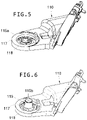
Figure 5 is a perspective view of the base bracket with the first example of the shaft formed with two sections; -
Figure 6 is a perspective view of the base bracket with a second example of the shaft formed with a single section; -
Figure 7 is a cross-sectional view of the present peripheral functional assembly using the first example, with both sections of the shaft attached through a screw; and -
Figure 8 is a cross-sectional view of the present peripheral functional assembly of the second example. - Examples of a peripheral
functional assembly 100 will be described in the following according to thefigures 1-8 of the drawings. - The peripheral
functional assembly 100 that is described herein comprises abase bracket 110. Thebase bracket 110 is fixedly attached to a motor vehicle, not shown. - The peripheral
functional assembly 100 further comprises anelectric actuator assembly 120 that is pivotally mounted to thebase bracket 110 through ashaft 115 that is fixedly attached to thebase bracket 110. Theelectric actuator assembly 120 comprises driving means 130 for causing theactuator assembly 120 itself to pivot relative to thebase bracket 110 around saidshaft 115. - The driving means 130 are enclosed within a
cover assembly 140. Thecover assembly 140 is arranged immediately adjacent the driving means 130, that is, adjoining at least one of amotor 135 or atransmission 136 of the driving means 130. - The
actuator assembly 120 can be moved along an axis z as shown infigure 1 throughramps figures 4 ,7, 8 of the drawings. Such movement of theactuator assembly 120 along an axis z is controlled by aspring 138 and is locked by alock washer 137 shown infigure 1 . Theactuator assembly 120 can be also rotated around the above mentionedshaft 115 which will be also described further below. - The
cover assembly 140, in addition of performing the function of housing, receiving, and enclosing the driving means 130 including themotor 135 and thetransmission 136, it is also configured for supporting afunctional element 200. - The
functional element 200 may be, for example, a mirror, an electrical device, such as a video camera, a photo camera, a light, a blinker, a radar, a LIDAR, etc, and in general any element intended for performing a specific function. Thecover assembly 140 thus integrates theelectric actuator assembly 120 therein and also thefunctional element 200. In the example shown, thefunctional element 200 is supported on thecover assembly 140. - As shown in the figures, the
cover assembly 140 comprises a first cover or upper cover, also referred herein to ashousing bracket 150, and a second cover orlower cover 160. In this non-limiting example, thehousing bracket 150 is intended to receive thefunctional element 200 supported therewith. For this purpose, thehousing bracket 150 is stiffer than thelower cover 160. Examples of ways for stiffening thehousing bracket 150 may be providing stiffening elements such as ribs, ridges, etc.; increasing the thickness of thehousing bracket 150 with respect to the lower cover, or selecting stiffer materials such as a metal, for example aluminium, magnesium or Zamak alloys, or a reinforced plastic material. Thespring 138 is arranged to bias thelower cover 160 to thebase bracket 110. - The
housing bracket 150 of the cover assembly has anextension 155 formed integrally therewith in the example shown. One free end of theextension 155 of thehousing bracket 150 is adapted to support thefunctional element 200. The resulting configuration is such that thehousing bracket 150 protrudes from thelower cover 160 away from the vehicle in a driving position, in a direction y depicted infigure 1 , transversely to a direction of travel, opposite to direction x depicted infigure 1 . Thus, thehousing bracket 150 is at least 30% longer than thelower cover 160, as illustrated in the figures of the drawings. - The
housing bracket 150 is countershaped to the driving means 130 for example countershaped to at least one of themotor 135 or thetransmission 136. - As described above, a
shaft 115 is associated withbase bracket 110. In a first example shown infigures 1 ,5 and7 theshaft 115 is divided into afirst shaft section 115a and asecond shaft section 115b, wherein thefirst shaft section 115a is the part attached to thebase bracket 110, in the example integral to thebase bracket 110. In second example shown infigures 6 and8 , theshaft 115 has a single shaft section, in the example the single shaft section is made integral with thebase bracket 110. - The
first shaft section 115a is attached to thebase bracket 110. Thefirst shaft section 115a is also attached to thesecond shaft section 115b that in use is inserted into acavity 116b formed therein. Thesecond shaft section 115b has arecess 116a that is formed in a distal end thereof. Therecess 116a is intended for receiving therein aplug 170, which will be described further below. - The
base bracket 110 has aprojection 156 arranged surrounding theshaft 115 externally or being arranged internally thereto. In the example, theprojection 156 is arranged internally in therecess 116a. Thisprojection 156 helps in guiding theelectric actuator assembly 120 as it is displaced axially along theshaft 115 according to axis z shown infigure 1 . - As stated above
plug 170 is provided for covering saidcavity 116a that is formed in ahollow end 116 of theshaft 115 fixedly attached to thebase bracket 110 in order to protect theassembly 100 from dust and moisture. Theplug 170 may also be placed within theprojection 156 when theprojection 156 arranged internally therecess 116a of theshaft 115. Theplug 170 is provided with afastener 180 for fixing cables over a central part of theshaft 115. This avoids cables to be stretched or shrunk as theelectric actuator assembly 120 is pivoted to thebase bracket 110 during operation. - The
base bracket 110 has anupper surface 117 with a series oframps 118 formed thereon. Theramps 118 are arranged such that, in use, interact with a series oframps 119 formed in a lower surface of thecover assembly 140 as shown infigures 4 ,7, 8 of the drawings and/or with other series or ramps formed in the driving means 130. - In the first example, when the
shaft 115 is divided in twosections first shaft section 115a is made integral with thebase bracket 110 and thesecond shaft section 115b is attached to thefirst shaft section 115a through ascrew 112. Thefirst shaft section 115a is inserted into thesecond shaft section 115b. This results in astiffer shaft 115. - A
top cover cap 190 and abottom cover cap 195 are provided for receiving therein the peripheralfunctional assembly 100 as shown infigure 1 . - Although only a number of particular embodiments and examples of the present winglet assembly for motor vehicles have been disclosed herein, it will be understood by those skilled in the art that other alternative examples and/or uses and obvious modifications and equivalents thereof are possible. The present disclosure covers all possible combinations of the particular examples described.
- The use of terms "first", "second", etc. for indicating different parts does not involve any order and does not necessarily exclude other further parts. Reference signs related to drawings and placed in parentheses in a claim, are solely for attempting to increase the intelligibility of the claim, and shall not be construed as limiting the scope of the claim.
- The scope of the present disclosure should not be limited by particular examples, but should be determined only by a fair reading of the claims that follow.
Claims (15)
- Peripheral functional assembly (100) for motor vehicles, the peripheral functional assembly (100) comprising:- a base bracket (110) to be fixedly attached to a motor vehicle; and- an electric actuator assembly (120) pivotally mounted to the base bracket (110), the electric actuator assembly (120) comprising:- driving means (130) for pivoting to the base bracket (110) and- a cover assembly (140);wherein the cover assembly (140) is arranged enclosing the driving means (130) immediately adjacent said driving means (130), and
wherein the cover assembly (140) is also configured for supporting a functional element (200). - The assembly (100) of claim 1, wherein the cover assembly (140) comprises at least a first cover (150) and a second cover (160).
- The assembly (100) of claim 1 or 2, wherein the cover assembly (140) has an extension (155) where the functional element (200) is supported.
- The assembly (100) of claim 3, wherein the extension (155) is integrally formed with at least one of the first cover (150) or the second cover (160).
- The assembly (100) of claim 3, wherein the extension (155) is removably formed with at least one of the first cover (150) or the second cover (160).
- The assembly (100) of any of claims 2-5, wherein the first cover (150) is at least 30% longer than the second cover (150).
- The assembly (100) of any of claims 2-6, wherein at least one of the first cover (150) or the second cover (160) is countershaped to at least one portion of the driving means (130).
- The assembly (100) of any of claims 1-7, wherein the base bracket (110) includes a shaft (115) having at least one hollow end (116) and the cover assembly (140) has a downward projection (156) surrounding the shaft (115) externally or arranged internally thereto.
- The assembly (100) of claim 8, wherein the downward projection (156) is arranged overlapping the shaft (115).
- The assembly (100) of claim 8 or 9, wherein it further includes a plug (170) for covering the hollow end (116) of the base bracket shaft (115) or the downward projection (156) arranged internally to the base bracket shaft (115).
- The assembly (100) of claim 10, wherein the plug has (170) a fastener (180) for fixing cables passing over the base bracket shaft (115).
- The assembly (100) of any of the claims 8-11, wherein the base bracket shaft (115) is divided into at least two sections (115a, 115b).
- The assembly (100) of the claims claim 8-12, wherein the shaft (115) is made integral with the base bracket (110).
- The assembly (100) of any of the preceding claims, wherein it comprises a series of ramps (118) formed in an upper surface (117) of the base bracket (110) which in use interact with a series of ramps (119) formed in a lower surface of the cover assembly (140).
- The assembly (100) of any of claims 2-14, wherein at least one of the first cover (150) or the second cover (160) is stiffer than the other cover.
Priority Applications (4)
| Application Number | Priority Date | Filing Date | Title |
|---|---|---|---|
| EP26152734.5A EP4722046A2 (en) | 2021-02-17 | 2021-02-17 | Peripheral functional assembly for motor vehicles |
| EP21382124.2A EP4046871B1 (en) | 2021-02-17 | 2021-02-17 | Peripheral functional assembly for motor vehicles |
| CN202210146824.4A CN114940123A (en) | 2021-02-17 | 2022-02-17 | Peripheral function module for a motor vehicle |
| US17/674,135 US20220258668A1 (en) | 2021-02-17 | 2022-02-17 | Peripheral functional assembly for motor vehicles |
Applications Claiming Priority (1)
| Application Number | Priority Date | Filing Date | Title |
|---|---|---|---|
| EP21382124.2A EP4046871B1 (en) | 2021-02-17 | 2021-02-17 | Peripheral functional assembly for motor vehicles |
Related Child Applications (1)
| Application Number | Title | Priority Date | Filing Date |
|---|---|---|---|
| EP26152734.5A Division EP4722046A2 (en) | 2021-02-17 | 2021-02-17 | Peripheral functional assembly for motor vehicles |
Publications (2)
| Publication Number | Publication Date |
|---|---|
| EP4046871A1 true EP4046871A1 (en) | 2022-08-24 |
| EP4046871B1 EP4046871B1 (en) | 2026-01-21 |
Family
ID=74732851
Family Applications (2)
| Application Number | Title | Priority Date | Filing Date |
|---|---|---|---|
| EP21382124.2A Active EP4046871B1 (en) | 2021-02-17 | 2021-02-17 | Peripheral functional assembly for motor vehicles |
| EP26152734.5A Pending EP4722046A2 (en) | 2021-02-17 | 2021-02-17 | Peripheral functional assembly for motor vehicles |
Family Applications After (1)
| Application Number | Title | Priority Date | Filing Date |
|---|---|---|---|
| EP26152734.5A Pending EP4722046A2 (en) | 2021-02-17 | 2021-02-17 | Peripheral functional assembly for motor vehicles |
Country Status (3)
| Country | Link |
|---|---|
| US (1) | US20220258668A1 (en) |
| EP (2) | EP4046871B1 (en) |
| CN (1) | CN114940123A (en) |
Families Citing this family (1)
| Publication number | Priority date | Publication date | Assignee | Title |
|---|---|---|---|---|
| EP4691853A1 (en) * | 2024-12-02 | 2026-02-11 | Ficosa Automotive, S.L.U. | System for attaching an indirect vision device to a vehicle |
Citations (5)
| Publication number | Priority date | Publication date | Assignee | Title |
|---|---|---|---|---|
| EP0860323A2 (en) * | 1997-02-19 | 1998-08-26 | Britax (Geco) S.A. | Vehicle exterior rear view mirror |
| JP2017039377A (en) * | 2015-08-19 | 2017-02-23 | 株式会社石▲崎▼本店 | Image display device for vehicle |
| CN107835341A (en) * | 2017-11-04 | 2018-03-23 | 魏景泉 | A kind of vehicle-mounted waterproof intelligent video camera head and its installation method |
| EP3663135A1 (en) | 2017-08-02 | 2020-06-10 | Ichikoh Industries, Ltd. | Electric retractable vehicle periphery viewing device |
| KR102135950B1 (en) * | 2020-01-15 | 2020-07-20 | 최병대 | Slim folding apparatus of rear mirror for vehicle |
Family Cites Families (3)
| Publication number | Priority date | Publication date | Assignee | Title |
|---|---|---|---|---|
| WO2007034853A1 (en) * | 2005-09-26 | 2007-03-29 | Kabushiki Kaisha Honda Lock | Integrated mirror device for vehicle |
| EP3524474B1 (en) * | 2018-02-13 | 2021-04-07 | Ficomirrors, S.A.U. | Connector arrangement for a motor vehicle rear-view mirror |
| DE102020103285B4 (en) * | 2019-02-26 | 2024-11-14 | Illinois Tool Works Inc. | ACTUATOR FOR OPENING AND CLOSING A COVER IN OR ON A VEHICLE AS NEEDED AND COVER WITH SUCH ACTUATOR |
-
2021
- 2021-02-17 EP EP21382124.2A patent/EP4046871B1/en active Active
- 2021-02-17 EP EP26152734.5A patent/EP4722046A2/en active Pending
-
2022
- 2022-02-17 US US17/674,135 patent/US20220258668A1/en active Pending
- 2022-02-17 CN CN202210146824.4A patent/CN114940123A/en active Pending
Patent Citations (5)
| Publication number | Priority date | Publication date | Assignee | Title |
|---|---|---|---|---|
| EP0860323A2 (en) * | 1997-02-19 | 1998-08-26 | Britax (Geco) S.A. | Vehicle exterior rear view mirror |
| JP2017039377A (en) * | 2015-08-19 | 2017-02-23 | 株式会社石▲崎▼本店 | Image display device for vehicle |
| EP3663135A1 (en) | 2017-08-02 | 2020-06-10 | Ichikoh Industries, Ltd. | Electric retractable vehicle periphery viewing device |
| CN107835341A (en) * | 2017-11-04 | 2018-03-23 | 魏景泉 | A kind of vehicle-mounted waterproof intelligent video camera head and its installation method |
| KR102135950B1 (en) * | 2020-01-15 | 2020-07-20 | 최병대 | Slim folding apparatus of rear mirror for vehicle |
Also Published As
| Publication number | Publication date |
|---|---|
| CN114940123A (en) | 2022-08-26 |
| EP4046871B1 (en) | 2026-01-21 |
| EP4722046A2 (en) | 2026-04-08 |
| US20220258668A1 (en) | 2022-08-18 |
Similar Documents
| Publication | Publication Date | Title |
|---|---|---|
| KR101433407B1 (en) | Apparatus and system for providing a virtual display for a vehicle | |
| US7813639B2 (en) | Camera cover | |
| EP1321334A2 (en) | Exterior rearview mirror with built-in camera | |
| US9630559B2 (en) | Vehicle visual recognition device | |
| EP1640215B1 (en) | Outside rear-view mirror assembly for vehicle, which is designed to support an image-detector device | |
| CN115959044B (en) | rearview mirror structure | |
| CN115959045B (en) | rearview mirror structure | |
| EP4046871B1 (en) | Peripheral functional assembly for motor vehicles | |
| KR20200086524A (en) | Camera Angle Adjustment Device | |
| EP0040168A1 (en) | Composite vent window and rear view mirror | |
| JP7470627B2 (en) | Rear Vision Device | |
| US20230234507A1 (en) | Exterior rear view assembly for road vehicles and method of manufacturing an exterior rear view assembly for road vehicles | |
| KR100684969B1 (en) | Surveillance Camera Installation Bracket | |
| EP3922515B1 (en) | Periphery visual recognition device for electric retractable vehicle | |
| JP7509669B2 (en) | Rear Vision Device | |
| JPH0747378B2 (en) | Vehicle side mirror | |
| KR102870476B1 (en) | Camera Apparatus | |
| CN219843672U (en) | Vehicle-mounted image pickup device | |
| KR101564354B1 (en) | Black-box for vehicle | |
| US12559030B2 (en) | Folding actuator cover assembly | |
| JP7470626B2 (en) | Rear Vision Device | |
| CN110901668A (en) | Motor train unit and rearview mirror thereof | |
| CN220752746U (en) | Vehicle type recognition equipment for road test type laser video fusion | |
| NL2033251B1 (en) | Truck comprising a camera housing that encloses a camera module | |
| EP1531085A1 (en) | Front-viewing system for vehicles |
Legal Events
| Date | Code | Title | Description |
|---|---|---|---|
| PUAI | Public reference made under article 153(3) epc to a published international application that has entered the european phase |
Free format text: ORIGINAL CODE: 0009012 |
|
| STAA | Information on the status of an ep patent application or granted ep patent |
Free format text: STATUS: THE APPLICATION HAS BEEN PUBLISHED |
|
| AK | Designated contracting states |
Kind code of ref document: A1 Designated state(s): AL AT BE BG CH CY CZ DE DK EE ES FI FR GB GR HR HU IE IS IT LI LT LU LV MC MK MT NL NO PL PT RO RS SE SI SK SM TR |
|
| STAA | Information on the status of an ep patent application or granted ep patent |
Free format text: STATUS: REQUEST FOR EXAMINATION WAS MADE |
|
| 17P | Request for examination filed |
Effective date: 20230224 |
|
| RBV | Designated contracting states (corrected) |
Designated state(s): AL AT BE BG CH CY CZ DE DK EE ES FI FR GB GR HR HU IE IS IT LI LT LU LV MC MK MT NL NO PL PT RO RS SE SI SK SM TR |
|
| STAA | Information on the status of an ep patent application or granted ep patent |
Free format text: STATUS: EXAMINATION IS IN PROGRESS |
|
| 17Q | First examination report despatched |
Effective date: 20230613 |
|
| 17Q | First examination report despatched |
Effective date: 20240626 |
|
| GRAP | Despatch of communication of intention to grant a patent |
Free format text: ORIGINAL CODE: EPIDOSNIGR1 |
|
| STAA | Information on the status of an ep patent application or granted ep patent |
Free format text: STATUS: GRANT OF PATENT IS INTENDED |
|
| INTG | Intention to grant announced |
Effective date: 20250808 |
|
| RAP1 | Party data changed (applicant data changed or rights of an application transferred) |
Owner name: FICOSA AUTOMOTIVE, S.L.U. |
|
| GRAS | Grant fee paid |
Free format text: ORIGINAL CODE: EPIDOSNIGR3 |
|
| GRAA | (expected) grant |
Free format text: ORIGINAL CODE: 0009210 |
|
| STAA | Information on the status of an ep patent application or granted ep patent |
Free format text: STATUS: THE PATENT HAS BEEN GRANTED |
|
| RAP3 | Party data changed (applicant data changed or rights of an application transferred) |
Owner name: FICOSA AUTOMOTIVE, S.L.U. |
|
| AK | Designated contracting states |
Kind code of ref document: B1 Designated state(s): AL AT BE BG CH CY CZ DE DK EE ES FI FR GB GR HR HU IE IS IT LI LT LU LV MC MK MT NL NO PL PT RO RS SE SI SK SM TR |
|
| REG | Reference to a national code |
Ref country code: CH Ref legal event code: F10 Free format text: ST27 STATUS EVENT CODE: U-0-0-F10-F00 (AS PROVIDED BY THE NATIONAL OFFICE) Effective date: 20260121 |
|
| REG | Reference to a national code |
Ref country code: DE Ref legal event code: R096 Ref document number: 602021046310 Country of ref document: DE |
|
| REG | Reference to a national code |
Ref country code: IE Ref legal event code: FG4D |
|
| PGFP | Annual fee paid to national office [announced via postgrant information from national office to epo] |
Ref country code: DE Payment date: 20260327 Year of fee payment: 6 |