EP4046861A1 - Notstromversorgungsvorrichtung eines schienenfahrzeugs - Google Patents
Notstromversorgungsvorrichtung eines schienenfahrzeugs Download PDFInfo
- Publication number
- EP4046861A1 EP4046861A1 EP22154604.7A EP22154604A EP4046861A1 EP 4046861 A1 EP4046861 A1 EP 4046861A1 EP 22154604 A EP22154604 A EP 22154604A EP 4046861 A1 EP4046861 A1 EP 4046861A1
- Authority
- EP
- European Patent Office
- Prior art keywords
- voltage battery
- volts
- low voltage
- battery
- high voltage
- Prior art date
- Legal status (The legal status is an assumption and is not a legal conclusion. Google has not performed a legal analysis and makes no representation as to the accuracy of the status listed.)
- Withdrawn
Links
- 238000006243 chemical reaction Methods 0.000 claims abstract description 102
- 230000002441 reversible effect Effects 0.000 claims description 33
- 238000000034 method Methods 0.000 claims description 32
- 230000006978 adaptation Effects 0.000 claims description 23
- 238000004146 energy storage Methods 0.000 claims description 6
- 210000000352 storage cell Anatomy 0.000 claims description 3
- WHXSMMKQMYFTQS-UHFFFAOYSA-N Lithium Chemical compound [Li] WHXSMMKQMYFTQS-UHFFFAOYSA-N 0.000 description 5
- 229910052744 lithium Inorganic materials 0.000 description 5
- 210000004027 cell Anatomy 0.000 description 2
- 238000013461 design Methods 0.000 description 2
- 230000007257 malfunction Effects 0.000 description 2
- 238000011144 upstream manufacturing Methods 0.000 description 2
- 238000009423 ventilation Methods 0.000 description 2
- 241001080024 Telles Species 0.000 description 1
- 230000015556 catabolic process Effects 0.000 description 1
- 238000006731 degradation reaction Methods 0.000 description 1
- 230000001934 delay Effects 0.000 description 1
- 238000010438 heat treatment Methods 0.000 description 1
- 230000003116 impacting effect Effects 0.000 description 1
- 238000009413 insulation Methods 0.000 description 1
- 230000003137 locomotive effect Effects 0.000 description 1
- 238000012986 modification Methods 0.000 description 1
- 230000004048 modification Effects 0.000 description 1
- 238000012544 monitoring process Methods 0.000 description 1
- 238000012546 transfer Methods 0.000 description 1
Images
Classifications
-
- B—PERFORMING OPERATIONS; TRANSPORTING
- B60—VEHICLES IN GENERAL
- B60L—PROPULSION OF ELECTRICALLY-PROPELLED VEHICLES; SUPPLYING ELECTRIC POWER FOR AUXILIARY EQUIPMENT OF ELECTRICALLY-PROPELLED VEHICLES; ELECTRODYNAMIC BRAKE SYSTEMS FOR VEHICLES IN GENERAL; MAGNETIC SUSPENSION OR LEVITATION FOR VEHICLES; MONITORING OPERATING VARIABLES OF ELECTRICALLY-PROPELLED VEHICLES; ELECTRIC SAFETY DEVICES FOR ELECTRICALLY-PROPELLED VEHICLES
- B60L58/00—Methods or circuit arrangements for monitoring or controlling batteries or fuel cells, specially adapted for electric vehicles
- B60L58/10—Methods or circuit arrangements for monitoring or controlling batteries or fuel cells, specially adapted for electric vehicles for monitoring or controlling batteries
- B60L58/18—Methods or circuit arrangements for monitoring or controlling batteries or fuel cells, specially adapted for electric vehicles for monitoring or controlling batteries of two or more battery modules
- B60L58/20—Methods or circuit arrangements for monitoring or controlling batteries or fuel cells, specially adapted for electric vehicles for monitoring or controlling batteries of two or more battery modules having different nominal voltages
-
- B—PERFORMING OPERATIONS; TRANSPORTING
- B60—VEHICLES IN GENERAL
- B60L—PROPULSION OF ELECTRICALLY-PROPELLED VEHICLES; SUPPLYING ELECTRIC POWER FOR AUXILIARY EQUIPMENT OF ELECTRICALLY-PROPELLED VEHICLES; ELECTRODYNAMIC BRAKE SYSTEMS FOR VEHICLES IN GENERAL; MAGNETIC SUSPENSION OR LEVITATION FOR VEHICLES; MONITORING OPERATING VARIABLES OF ELECTRICALLY-PROPELLED VEHICLES; ELECTRIC SAFETY DEVICES FOR ELECTRICALLY-PROPELLED VEHICLES
- B60L50/00—Electric propulsion with power supplied within the vehicle
- B60L50/50—Electric propulsion with power supplied within the vehicle using propulsion power supplied by batteries or fuel cells
- B60L50/53—Electric propulsion with power supplied within the vehicle using propulsion power supplied by batteries or fuel cells in combination with an external power supply, e.g. from overhead contact lines
-
- B—PERFORMING OPERATIONS; TRANSPORTING
- B60—VEHICLES IN GENERAL
- B60L—PROPULSION OF ELECTRICALLY-PROPELLED VEHICLES; SUPPLYING ELECTRIC POWER FOR AUXILIARY EQUIPMENT OF ELECTRICALLY-PROPELLED VEHICLES; ELECTRODYNAMIC BRAKE SYSTEMS FOR VEHICLES IN GENERAL; MAGNETIC SUSPENSION OR LEVITATION FOR VEHICLES; MONITORING OPERATING VARIABLES OF ELECTRICALLY-PROPELLED VEHICLES; ELECTRIC SAFETY DEVICES FOR ELECTRICALLY-PROPELLED VEHICLES
- B60L2200/00—Type of vehicles
- B60L2200/26—Rail vehicles
-
- B—PERFORMING OPERATIONS; TRANSPORTING
- B60—VEHICLES IN GENERAL
- B60L—PROPULSION OF ELECTRICALLY-PROPELLED VEHICLES; SUPPLYING ELECTRIC POWER FOR AUXILIARY EQUIPMENT OF ELECTRICALLY-PROPELLED VEHICLES; ELECTRODYNAMIC BRAKE SYSTEMS FOR VEHICLES IN GENERAL; MAGNETIC SUSPENSION OR LEVITATION FOR VEHICLES; MONITORING OPERATING VARIABLES OF ELECTRICALLY-PROPELLED VEHICLES; ELECTRIC SAFETY DEVICES FOR ELECTRICALLY-PROPELLED VEHICLES
- B60L2210/00—Converter types
- B60L2210/10—DC to DC converters
-
- Y—GENERAL TAGGING OF NEW TECHNOLOGICAL DEVELOPMENTS; GENERAL TAGGING OF CROSS-SECTIONAL TECHNOLOGIES SPANNING OVER SEVERAL SECTIONS OF THE IPC; TECHNICAL SUBJECTS COVERED BY FORMER USPC CROSS-REFERENCE ART COLLECTIONS [XRACs] AND DIGESTS
- Y02—TECHNOLOGIES OR APPLICATIONS FOR MITIGATION OR ADAPTATION AGAINST CLIMATE CHANGE
- Y02T—CLIMATE CHANGE MITIGATION TECHNOLOGIES RELATED TO TRANSPORTATION
- Y02T10/00—Road transport of goods or passengers
- Y02T10/60—Other road transportation technologies with climate change mitigation effect
- Y02T10/70—Energy storage systems for electromobility, e.g. batteries
Definitions
- the present invention relates to an emergency power supply device for a railway vehicle. It also relates to an emergency power supply method implementing such a device and a railway vehicle comprising such a device.
- the field of the invention is the railway field, and more particularly the field of emergency power supply devices for rail vehicles when the latter cannot be powered by an external energy source such as a catenary.
- Rail vehicles are powered by external sources, called catenaries. Malfunctions occurring in the power supply of rail vehicles create safety problems and cause long delays.
- Power supply devices are known which make it possible to respond to malfunctions in the power supply of a railway vehicle.
- one solution is to use a battery on board said vehicle to power both the traction of said vehicle and the auxiliary equipment.
- the object of the invention is to overcome the aforementioned drawbacks.
- an object of the invention is to propose an emergency power supply device for a railway vehicle making it possible to guarantee optimum operation of said vehicle.
- Another object of the invention is to provide an emergency power supply device for a railway vehicle with increased autonomy over time.
- Another object of the invention is to propose an emergency supply device for a railway vehicle, which is lighter and less bulky.
- the device according to the invention is arranged so that, when the charge level of said low voltage battery is less than or equal to a first threshold, the high voltage and low voltage battery are connected to each other via a second power conversion unit so that said low voltage battery is powered by said high voltage battery.
- the high voltage battery supplies the low voltage battery, which makes it possible to maintain optimal operation, ie without degradation of performance or comfort.
- an external energy source such as a catenary.
- the transfer of energy between the high voltage battery to the low voltage battery also makes it possible to extend the power supply to the auxiliary equipment, which makes it possible, among other things, to increase the autonomy time of the vehicle's battery power supply.
- the device according to the invention makes it possible to optimize the mass and the volume of the high and low voltage batteries.
- the connection between the high voltage and low voltage batteries makes it possible to reduce the size and the mass of the low voltage battery because the high voltage battery can provide part of the energy necessary for the low voltage battery, thus acting as a reservoir energy for the low voltage battery.
- the device according to the invention is therefore lighter and less bulky than the devices of the prior art.
- “Auxiliary equipment” means any electrical device or appliance located within the railway vehicle, other than the elements of the traction chain such as the electric traction motor(s), also called “traction motor”.
- battery any electrical energy storage module, in particular rechargeable, which may comprise one or more electrical energy storage elements.
- battery can designate a set of several batteries, or several electrical energy storage modules, possibly distributed within the electric vehicle.
- the voltage delivered by the high voltage and/or low voltage battery is preferably a DC direct voltage.
- high voltage is meant an electrical signal with a voltage greater than or equal to 750 volts.
- intermediate voltage an electrical signal with a voltage of between 120 volts and 750 volts.
- Low voltage means an electrical signal with a voltage less than or equal to 120 volts.
- the nominal voltage of the low voltage battery can be 72 volts or 110 volts direct current DC.
- the first threshold can be less than or equal to 90 or 91% of the nominal charge level of the low voltage battery.
- nominal voltage or “nominal load level” is meant an optimum voltage for use or an optimal level of load for use.
- the second emergency power conversion unit of the device according to the invention may comprise an adaptation converter and an isolated reversible converter, said isolated reversible converter possibly comprising a conversion factor greater than that of the adaptation converter, in especially between two and ten times larger, and preferably nine times larger.
- the second power unit converts a high voltage electrical signal into a low voltage electrical signal.
- the difference in conversion factor between the two converters belonging to the second power conversion unit makes it possible to obtain a more precise conversion and therefore to guarantee an optimal conversion of the high voltage electrical signal into a desired low voltage electrical signal.
- the reversible converter isolated from the device according to the invention can be arranged to convert a high voltage electrical signal greater than 750 volts, preferably greater than or equal to 750 volts, and more particularly a high voltage electrical signal equal to 750 volts, or 1200 volts into an electrical signal with a voltage of less than 120 volts, preferably equal to 80 volts.
- the adaptation converter of the device according to the invention can be arranged to convert an electrical signal with a voltage of less than or equal to 120 volts, and more particularly equal to 80 volts, into an electrical signal with a voltage of less than 80 volts, preferably equal to 72 volts.
- the adaptation converter of the device according to the invention can be arranged to supply the low voltage battery with an electrical signal of voltage between 70 volts and 120 volts, preferably equal to 72 volts.
- the device according to the invention when the train is powered by its external source, that is to say during the nominal operation of the vehicle, the device according to the invention is loaded by the “conventional” components involved in the nominal operation of the vehicle.
- the batteries used in the emergency power supply device are therefore rechargeable and therefore reusable and do not require the use of an additional element not present in the nominal mode of the vehicle.
- the charge level of the high voltage battery of the device according to the invention is greater than a second threshold, said high voltage battery can be arranged to supply the first power conversion unit, which can supply at least one auxiliary equipment
- the second threshold can be greater than 1200 volts, preferably equal to 1200 volts or 1500 volts in DC direct voltage.
- the high voltage battery and/or the low voltage battery of the device according to the invention can consist of one or more series-connected battery modules each comprising several energy storage cells.
- the emergency device according to the invention is adaptable to different types and designs of batteries.
- the high voltage battery of the device according to the invention may consist of at least two batteries each delivering a voltage lower than the output voltage of said high voltage battery, and connected in series by a switch.
- the high voltage battery can be arranged to deliver a high voltage electrical signal greater than 750 volts, preferably greater than or equal to 750 volts, and more particularly an electrical signal with a voltage equal to 750 volts, or 1200 volts.
- the low voltage battery of the device according to the invention may have a lower energy density than that of the high voltage battery of the device according to the invention, in particular between two and twelve times lower, and preferably ten times lower. .
- the size of the low voltage battery can be "reduced” compared to conventional systems in which the low voltage battery comprises a high energy density to ensure the supply of energy necessary for the needs. of the rail vehicle.
- the size of the low voltage battery is smaller because the high voltage battery can supply energy to the components of the rail vehicle, which compensates for the energy which the low voltage battery must supply.
- the device according to the invention therefore makes it possible to optimize the energy density of the low voltage battery.
- the low voltage battery is therefore less voluminous than that used in conventional systems.
- the high voltage battery and/or the low voltage battery of the device according to the invention can comprise a lithium battery.
- the low voltage battery of the device according to the invention can be arranged to power the auxiliary equipment for at least three hours.
- the emergency device according to the invention can operate for a long period of time, which allows the vehicle to reach remote stations or stopping stations for a pick-up of said vehicle.
- the low voltage battery of the device according to the invention can be arranged to supply at least one safety device.
- a railway vehicle comprising a supply device according to the invention.
- Such a railway vehicle can be a train, a locomotive, etc.
- the method according to the invention guarantees the same advantages as the device according to the invention.
- the method according to the invention therefore makes it possible to guarantee optimal operation of the vehicle when the latter is powered by batteries, which makes it possible, among other things, to increase the time of operation by batteries.
- the method according to the invention allows the device according to the invention to be less bulky and less heavy.
- the method according to the invention can comprise a power supply by the low-voltage battery matching converter with an electrical signal with a voltage of between 70 volts and 120 volts, preferably equal to 72 volts.
- the low voltage battery of the method according to the invention can be arranged to supply at least one safety device.
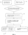
- the FIGURE 1 is a schematic representation of a non-limiting exemplary embodiment of a method according to the invention.
- the method 100 is a method for emergency powering a rail vehicle when said rail vehicle is no longer powered by an external power source, such as a catenary.
- the method 100 then comprises a supply 102 of the traction chain of the railway vehicle via a first power conversion unit.
- the first power conversion unit is powered by a high voltage battery supplying a high voltage electrical signal.
- the method 100 also includes a power supply 104, by a low voltage battery delivering a low voltage electric signal, of at least one auxiliary equipment.
- the high voltage battery is arranged to supply the traction chain of the vehicle via the first power conversion unit.
- the low voltage battery is arranged to supply at least one auxiliary equipment.
- the first threshold can be reached when the charge level of the low voltage battery is less than or equal to 91% or 90% of the nominal charge level of the low voltage battery.
- the traction chain remains powered by said high voltage battery and the at least one auxiliary remains powered by the low voltage battery.
- the traction chain of said vehicle is no longer powered by the high voltage battery.
- the first power conversion unit when the vehicle is stationary, can be powered by the high voltage battery even if the rail vehicle has to remain stationary.
- the supply of the traction chain is interrupted by the control device following, for example, a command from the driver of said vehicle. The movement of the vehicle is blocked.
- the power supply 102 of the traction chain via the first power conversion unit by the high voltage battery is stopped by the control device. No energy is sent to the first power conversion unit.
- the low voltage battery can for its part continue to supply 104 the auxiliaries of the vehicle.
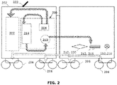
- the FIGURE 2 is a first schematic representation of an embodiment of a device according to the invention, in a configuration in which the railway vehicle is not powered by an external source.
- the device 200 of the FIGURE 2 is an autonomous emergency power supply device for a railway vehicle 202, on board said railway vehicle 202.
- the device 200 is used when said railway vehicle 202 is no longer powered by an external power source, for example during a power failure.
- the device 200 is arranged so that, when the charge level of said low voltage battery 210 is less than or equal to the first threshold, the high voltage 204 and low voltage 210 battery are connected to each other via a second unit converter 214 so that said low voltage battery 210 is powered by said high voltage battery 204.
- the high voltage 204 and low voltage 210 battery are arranged to deliver a direct DC voltage.
- this first threshold can be reached when the charge level of the low voltage battery is equal to 66 volts direct current DC.
- the second power conversion unit 214 makes it possible to convert a high voltage electric signal into a low voltage electric signal.
- the high voltage battery 204 is arranged to supply the traction chain 206 of the railway vehicle 202 via the first power conversion unit 208.
- the low voltage battery 210 is arranged to supply at least one auxiliary equipment 212.
- the low voltage battery 210 can power the auxiliary equipment 212 cumulatively or alternately.
- the traction chain 206 comprises at least one motor (not shown) arranged to transform the electrical energy at the output of the first power conversion unit 208 into mechanical energy to move the rail vehicle 202 forward and mechanical components to make the advancement of said vehicle 202.
- the external power source may be a catenary (not shown).
- the vehicle comprises a pantograph 222 arranged to, when the railway vehicle 202 is connected to the external energy source, capture electrical energy from the catenary. On the FIGURE 2 , the pantograph 222 is not connected to the external power source.
- the first power conversion unit 208 is arranged to change the form of electrical energy, for example converting alternating current AC into direct current DC; or convert DC direct current to AC alternating current, etc.
- High voltage battery 204 and/or low voltage battery 210 may include a lithium battery.
- the high voltage 204 and low voltage 210 batteries can be lithium batteries.
- the low voltage battery 210 can be sized to power auxiliary equipment for at least three hours.
- the low voltage battery can comprise a lower energy density than that of the high voltage battery, in particular between two and twelve times lower, and preferably ten times lower.
- the low voltage battery is therefore more compact than that which can be used in conventional systems.
- the railway vehicle 202 which can for example be a train
- the traction chain 206 of the vehicle 202 can be blocked by a control device (not illustrated).
- the traction chain of said vehicle 202 is no longer powered by the high voltage battery 204.
- the device 200 is arranged to implement the steps of the method 100 of the FIGURE 1 .
- the low voltage battery 210 is arranged to power at least one safety device 220.
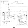
- the FIGURE 3 is a schematic representation of an embodiment of an electrical circuit of a device according to the invention, and in particular of the device 200 of the FIGURE 2 .
- the second emergency power conversion unit 214 includes a matching converter 302 and an isolated reversible converter 304.
- the isolated reversible converter 304 is arranged to serve as an interface between the high voltage battery 204 and the adaptation converter 302. Thus, the isolated reversible converter 304 is connected to the high voltage battery 204 and to the adaptation converter 302.
- the adaptation converter 302 is arranged to serve as an interface between the isolated reversible converter 304 and the low voltage battery 210. Thus, the adaptation converter is connected to the low voltage battery 210 and to the isolated reversible converter 304.
- the isolated reversible converter 304 comprises a greater conversion factor than that of the adaptation converter 302, in particular between two and ten times greater, and preferably nine times greater.
- the isolated reversible converter 304 is arranged to convert a high voltage electrical signal greater than 750 volts, preferably greater than or equal to 750 volts, and more particularly a high voltage electrical signal equal to 750 volts, or 1200 volts into an electrical signal with a voltage of less than 120 volts, preferably equal to 80 volts.
- the matching converter 302 is arranged to convert an electrical signal with a voltage of less than or equal to 120 volts, and more particularly equal to 80 volts, into an electrical signal with a voltage of less than 80 volts, preferably equal to 72 volts.
- the high voltage battery 204 is a lithium battery composed of several modules connected in series, which are themselves formed of several cells.
- the high voltage battery 204 is arranged to deliver a voltage of 750 volts (V), with a capacity of 23 Ampere hours (Ah) and a minimum energy of 10 kilowatt hours (kWh).
- the high voltage battery is also arranged to provide a voltage greater than 1200 V upstream of a main direct current circuit breaker (not shown), which via the first conversion unit 208 (not shown in this figure), supplies the vehicle traction motors 202.
- the high voltage battery 204 supplies the low voltage battery 210 and thus serves as an energy reserve. additional for the low voltage battery 210.
- the supply of the low voltage battery 210 by the high voltage battery 204 makes it possible to guarantee a longer supply of energy to the auxiliary equipment.
- the low voltage battery 210 is a lithium battery composed of several modules connected in series, which are themselves formed of several cells.
- the low voltage battery 210 is arranged to deliver a voltage of 72 V, with a capacity of 230 Ah and an energy of 16.5 kWh.
- the low voltage battery 210 supplies with a direct voltage (DC) of 72 V the auxiliary equipment of the train such as for example lighting, ventilation, etc.
- DC direct voltage
- the high voltage battery 204 and the low voltage battery 210 consist of one or more battery modules connected in series each comprising several energy storage cells.
- High voltage battery 204 is connected upstream of a DC DC main circuit breaker (not shown).
- the high voltage battery 204 produces a supply voltage equivalent to that injected into the main DC signal circuit breaker of the railway vehicle.
- the low voltage battery 210 has a lower energy density than the high voltage battery 204 and is connected to supply all the auxiliary equipment 212 operating at low voltage.
- the high voltage battery 204 consists of at least two batteries delivering a voltage lower than the output voltage of said high voltage battery, for example two medium voltage batteries, connected in series by a switch.
- Matching converter 302 is a DC/DC direct voltage converter and is connected to low voltage battery 210 and to a battery charger 306. Battery charger 306 is arranged to ensure adequate charging of low voltage battery 210 when the vehicle 202 is powered by the external source. Matching converter 302 is also connected to isolated reversible converter 304. Matching converter 302 is arranged to supply the low voltage battery with an electrical signal with a voltage between 70 volts and 120 volts, preferably equal to 72 volts. In the case considered, the battery charger 306 and the matching converter are arranged to supply the low voltage battery 210 with a direct DC voltage of 72 volts (V).
- Battery charger 306 is connected to matching converter 302 via a first node 316.
- the isolated reversible converter 304 is a DC/DC direct voltage converter and is arranged to convert a voltage of +/- 750 V into a voltage of +/- 80 V.
- the isolated reversible converter 304 is a 4 kilowatt (kW) power converter connecting the voltage +/- 750 V direct current DC and the low voltage network +/- 80 V direct current DC and including an insulation level of 4 kV.
- the isolated reversible converter 304 is arranged to charge the high voltage battery 204 when the vehicle 202 is powered by the external energy source.
- Isolated reversible converter 304 is connected to matching converter 302, which is connected to low voltage battery 210, to allow high voltage battery 204 to power low voltage battery 210 when the battery charge level is low.
- voltage 210 is less than or equal to the first threshold.
- the first threshold can be reached when the charge level of the low voltage battery 210 is 50 V direct current DC.
- Switching, monitoring and safety devices corresponding for example to contactors, diodes, etc., are also illustrated in picture 3 .
- First switches 308 are arranged to connect or disconnect the high voltage battery 204 to the first power conversion unit 208 (not illustrated in picture 3 ), i.e. to the "main" conversion system of the railway vehicle.
- Second switches 310 are arranged to connect or disconnect the high voltage battery 204 with the second power conversion unit 214, in particular via the isolated reversible converter 304.
- the high voltage battery 204 can be connected to the first power conversion unit 208 without being connected to the second power conversion unit 214.
- Auxiliary equipment (not shown in picture 3 ) are connected to the low voltage battery through a node 314.
- the supply of the low voltage battery 210 by the high voltage battery 204 is controlled and/or monitored by the control device (not shown).
- the control device is arranged to control and control the high batteries 204 and low voltage 210.
- This battery control device is also connected to the second power conversion unit 214.
- This battery control device is notably connected to the isolated reversible converter 304 and to the matching converter 302.
- control device is arranged to control the opening or closing of the first, second and third switches 308, 310, 312 simultaneously or alternately.
- the high voltage battery 204 and/or the low voltage battery 210 may not be connected to the second power conversion unit 214 when the switches 308 and/or 310 and/or 312 are open. Furthermore, the high voltage 204 and low voltage 210 batteries are not necessarily connected to each other when the switches 308 and/or 310 and/or 312 are open.
- the high voltage battery 204 when the charge level of the high voltage battery 204 is greater than a second threshold, said high voltage battery 204 is arranged to supply the first power conversion unit 208, which supplies at least one auxiliary equipment 212
- the second threshold can be 1200 V DC direct voltage or 1500 V DC direct voltage.
- the high voltage battery 204 when the high voltage battery 204 is not connected to the second power conversion unit 214, the high voltage battery 204 is in charge of supplying the energy and the power necessary to rescue the vehicle 202 and allow it to drop off passengers at the next station.
- the power generated by the high voltage battery 204 will make it possible, via the first power conversion unit 208, to supply the traction chain 206 and at least one auxiliary equipment 212.
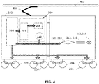
- the FIGURE 4 is a schematic representation of the device of the FIGURE 2 , in a configuration in which the railway vehicle is powered by an external source.
- the external source 402 is a catenary 402.
- Part of the energy captured by the catenary is used to recharge the high voltage battery and the low voltage battery.
- the first power unit 208 supplies the second power conversion unit 214.
- the auxiliary equipment is supplied with low voltage by the first power conversion unit directly via the battery charger 306, the latter being connected to the low voltage battery via the adaptation converter 302.
- the device 200 of the FIGURE 4 is arranged to carry out the steps of the method 100 of the FIGURE 1 .
Landscapes
- Engineering & Computer Science (AREA)
- Life Sciences & Earth Sciences (AREA)
- Sustainable Development (AREA)
- Sustainable Energy (AREA)
- Power Engineering (AREA)
- Transportation (AREA)
- Mechanical Engineering (AREA)
- Stand-By Power Supply Arrangements (AREA)
- Electric Propulsion And Braking For Vehicles (AREA)
Applications Claiming Priority (1)
| Application Number | Priority Date | Filing Date | Title |
|---|---|---|---|
| FR2101548A FR3119822B1 (fr) | 2021-02-18 | 2021-02-18 | dispositif d’alimentation d’urgence d’un vehicule ferroviaire |
Publications (1)
| Publication Number | Publication Date |
|---|---|
| EP4046861A1 true EP4046861A1 (de) | 2022-08-24 |
Family
ID=75339933
Family Applications (1)
| Application Number | Title | Priority Date | Filing Date |
|---|---|---|---|
| EP22154604.7A Withdrawn EP4046861A1 (de) | 2021-02-18 | 2022-02-01 | Notstromversorgungsvorrichtung eines schienenfahrzeugs |
Country Status (2)
| Country | Link |
|---|---|
| EP (1) | EP4046861A1 (de) |
| FR (1) | FR3119822B1 (de) |
Cited By (1)
| Publication number | Priority date | Publication date | Assignee | Title |
|---|---|---|---|---|
| CN116946194A (zh) * | 2023-07-27 | 2023-10-27 | 中车青岛四方机车车辆股份有限公司 | 一种列车的紧急供电控制方法、装置及列车 |
Citations (3)
| Publication number | Priority date | Publication date | Assignee | Title |
|---|---|---|---|---|
| WO2017148496A1 (en) * | 2016-03-01 | 2017-09-08 | Volvo Truck Corporation | A method and system for controlling a current being fed to a battery pack |
| EP3269581A1 (de) * | 2016-07-12 | 2018-01-17 | SNCF Mobilités | Leistungsversorgungssystem für schienenfahrzeug und schienenfahrzeug umfassend das leistungsversorgungssystem |
| US20200353828A1 (en) * | 2019-05-07 | 2020-11-12 | Dr. Ing. H.C. F. Porsche Aktiengesellschaft | Method and apparatus for charging an electric vehicle using a charging cable |
-
2021
- 2021-02-18 FR FR2101548A patent/FR3119822B1/fr active Active
-
2022
- 2022-02-01 EP EP22154604.7A patent/EP4046861A1/de not_active Withdrawn
Patent Citations (3)
| Publication number | Priority date | Publication date | Assignee | Title |
|---|---|---|---|---|
| WO2017148496A1 (en) * | 2016-03-01 | 2017-09-08 | Volvo Truck Corporation | A method and system for controlling a current being fed to a battery pack |
| EP3269581A1 (de) * | 2016-07-12 | 2018-01-17 | SNCF Mobilités | Leistungsversorgungssystem für schienenfahrzeug und schienenfahrzeug umfassend das leistungsversorgungssystem |
| US20200353828A1 (en) * | 2019-05-07 | 2020-11-12 | Dr. Ing. H.C. F. Porsche Aktiengesellschaft | Method and apparatus for charging an electric vehicle using a charging cable |
Cited By (1)
| Publication number | Priority date | Publication date | Assignee | Title |
|---|---|---|---|---|
| CN116946194A (zh) * | 2023-07-27 | 2023-10-27 | 中车青岛四方机车车辆股份有限公司 | 一种列车的紧急供电控制方法、装置及列车 |
Also Published As
| Publication number | Publication date |
|---|---|
| FR3119822A1 (fr) | 2022-08-19 |
| FR3119822B1 (fr) | 2025-06-13 |
Similar Documents
| Publication | Publication Date | Title |
|---|---|---|
| EP2684274B1 (de) | Ladungsausgleichssysteme für batterien | |
| EP3016817B1 (de) | Elektrofahrzeug und verbundene transporteinrichtung | |
| EP2781001B1 (de) | Gleichspannungsquelle einschliesslich brennstoffzellen mit anpassungfähigem spannungspegel | |
| EP3224923B1 (de) | Batteriepack für ein kraftfahrzeug | |
| FR2976737A1 (fr) | Element de batterie securise | |
| EP4046861A1 (de) | Notstromversorgungsvorrichtung eines schienenfahrzeugs | |
| FR3053851A1 (fr) | Dispositif de commande d'un systeme d'alimentation pour vehicule a couplage pile a combustible/batteries | |
| FR3101489A1 (fr) | Chargeur électrique pour équipement de maintenance aéronautique | |
| EP3981056B1 (de) | Wiederaufladbare elektrische energiespeichervorrichtung und system, fahrzeug und anlage mit einem solchen system | |
| FR3074984A1 (fr) | Convertisseur continu-continu avec pre-charge d’un premier reseau electrique a partir d’un deuxieme reseau electrique | |
| FR2994896A1 (fr) | Dispositif de stockage d'electricite comportant une batterie a haute tension et une batterie a basse tension de type lithium-ion | |
| EP3269581B1 (de) | Leistungsversorgungssystem für schienenfahrzeug und schienenfahrzeug umfassend das leistungsversorgungssystem | |
| US20240106259A1 (en) | Power-densifying charging station | |
| EP3594047B1 (de) | Regulierungsverfahren der elektrischen sofortleistung, die einem schienenfahrzeug von einer externen quelle geliefert wird | |
| EP3377366A1 (de) | Verfahren und system zum elektrischen aufladen eines elektrofahrzeugs | |
| WO2022018226A1 (fr) | Systeme d'alimentation d'un moteur de traction | |
| WO2020002820A1 (fr) | Système de stockage d'énergie embarqué | |
| FR3164155A1 (fr) | Procede de commande d’un systeme electrique polyphase pour une charge rapide en tension continue | |
| EP4406772A1 (de) | Schienenfahrzeug mit stromspeicherung | |
| EP4721225A1 (de) | Verfahren zur steuerung einer batterieladung eines mehrphasigen elektrischen systems zur erzeugung einer gleichspannung durch schalten der stromleitungen | |
| FR3138561A1 (fr) | Ensemble electrique pour securiser un reseau electrique haute tension d’un vehicule automobile electrifie | |
| FR3119572A1 (fr) | véhicule de traction embarquant un dispositif de stockage d’énergie électrique | |
| EP4410629A1 (de) | Zugsystem für ein schienenfahrzeug und entsprechendes schienenfahrzeug | |
| FR3019395A1 (fr) | Systeme d'alimentation d'une machine electrique de traction d'un vehicule hybride, pour la recharge de sa batterie par un reseau exterieur | |
| FR2912850A1 (fr) | Vehicule de transport en commun, procede d'utilisation et bloc batterie pour ce vehicule |
Legal Events
| Date | Code | Title | Description |
|---|---|---|---|
| PUAI | Public reference made under article 153(3) epc to a published international application that has entered the european phase |
Free format text: ORIGINAL CODE: 0009012 |
|
| STAA | Information on the status of an ep patent application or granted ep patent |
Free format text: STATUS: THE APPLICATION HAS BEEN PUBLISHED |
|
| AK | Designated contracting states |
Kind code of ref document: A1 Designated state(s): AL AT BE BG CH CY CZ DE DK EE ES FI FR GB GR HR HU IE IS IT LI LT LU LV MC MK MT NL NO PL PT RO RS SE SI SK SM TR |
|
| STAA | Information on the status of an ep patent application or granted ep patent |
Free format text: STATUS: THE APPLICATION IS DEEMED TO BE WITHDRAWN |
|
| 18D | Application deemed to be withdrawn |
Effective date: 20230225 |