EP4046860A1 - Electric vehicle - Google Patents
Electric vehicle Download PDFInfo
- Publication number
- EP4046860A1 EP4046860A1 EP21215201.1A EP21215201A EP4046860A1 EP 4046860 A1 EP4046860 A1 EP 4046860A1 EP 21215201 A EP21215201 A EP 21215201A EP 4046860 A1 EP4046860 A1 EP 4046860A1
- Authority
- EP
- European Patent Office
- Prior art keywords
- electric vehicle
- power
- power supply
- supply device
- base
- Prior art date
- Legal status (The legal status is an assumption and is not a legal conclusion. Google has not performed a legal analysis and makes no representation as to the accuracy of the status listed.)
- Pending
Links
Images


Classifications
-
- B—PERFORMING OPERATIONS; TRANSPORTING
- B60—VEHICLES IN GENERAL
- B60K—ARRANGEMENT OR MOUNTING OF PROPULSION UNITS OR OF TRANSMISSIONS IN VEHICLES; ARRANGEMENT OR MOUNTING OF PLURAL DIVERSE PRIME-MOVERS IN VEHICLES; AUXILIARY DRIVES FOR VEHICLES; INSTRUMENTATION OR DASHBOARDS FOR VEHICLES; ARRANGEMENTS IN CONNECTION WITH COOLING, AIR INTAKE, GAS EXHAUST OR FUEL SUPPLY OF PROPULSION UNITS IN VEHICLES
- B60K1/00—Arrangement or mounting of electrical propulsion units
- B60K1/04—Arrangement or mounting of electrical propulsion units of the electric storage means for propulsion
-
- B—PERFORMING OPERATIONS; TRANSPORTING
- B60—VEHICLES IN GENERAL
- B60L—PROPULSION OF ELECTRICALLY-PROPELLED VEHICLES; SUPPLYING ELECTRIC POWER FOR AUXILIARY EQUIPMENT OF ELECTRICALLY-PROPELLED VEHICLES; ELECTRODYNAMIC BRAKE SYSTEMS FOR VEHICLES IN GENERAL; MAGNETIC SUSPENSION OR LEVITATION FOR VEHICLES; MONITORING OPERATING VARIABLES OF ELECTRICALLY-PROPELLED VEHICLES; ELECTRIC SAFETY DEVICES FOR ELECTRICALLY-PROPELLED VEHICLES
- B60L53/00—Methods of charging batteries, specially adapted for electric vehicles; Charging stations or on-board charging equipment therefor; Exchange of energy storage elements in electric vehicles
- B60L53/80—Exchanging energy storage elements, e.g. removable batteries
-
- A—HUMAN NECESSITIES
- A01—AGRICULTURE; FORESTRY; ANIMAL HUSBANDRY; HUNTING; TRAPPING; FISHING
- A01D—HARVESTING; MOWING
- A01D69/00—Driving mechanisms or parts thereof for harvesters or mowers
- A01D69/02—Driving mechanisms or parts thereof for harvesters or mowers electric
-
- B—PERFORMING OPERATIONS; TRANSPORTING
- B60—VEHICLES IN GENERAL
- B60K—ARRANGEMENT OR MOUNTING OF PROPULSION UNITS OR OF TRANSMISSIONS IN VEHICLES; ARRANGEMENT OR MOUNTING OF PLURAL DIVERSE PRIME-MOVERS IN VEHICLES; AUXILIARY DRIVES FOR VEHICLES; INSTRUMENTATION OR DASHBOARDS FOR VEHICLES; ARRANGEMENTS IN CONNECTION WITH COOLING, AIR INTAKE, GAS EXHAUST OR FUEL SUPPLY OF PROPULSION UNITS IN VEHICLES
- B60K11/00—Arrangement in connection with cooling of propulsion units
- B60K11/06—Arrangement in connection with cooling of propulsion units with air cooling
-
- B—PERFORMING OPERATIONS; TRANSPORTING
- B60—VEHICLES IN GENERAL
- B60L—PROPULSION OF ELECTRICALLY-PROPELLED VEHICLES; SUPPLYING ELECTRIC POWER FOR AUXILIARY EQUIPMENT OF ELECTRICALLY-PROPELLED VEHICLES; ELECTRODYNAMIC BRAKE SYSTEMS FOR VEHICLES IN GENERAL; MAGNETIC SUSPENSION OR LEVITATION FOR VEHICLES; MONITORING OPERATING VARIABLES OF ELECTRICALLY-PROPELLED VEHICLES; ELECTRIC SAFETY DEVICES FOR ELECTRICALLY-PROPELLED VEHICLES
- B60L50/00—Electric propulsion with power supplied within the vehicle
- B60L50/50—Electric propulsion with power supplied within the vehicle using propulsion power supplied by batteries or fuel cells
- B60L50/51—Electric propulsion with power supplied within the vehicle using propulsion power supplied by batteries or fuel cells characterised by AC-motors
-
- B—PERFORMING OPERATIONS; TRANSPORTING
- B60—VEHICLES IN GENERAL
- B60L—PROPULSION OF ELECTRICALLY-PROPELLED VEHICLES; SUPPLYING ELECTRIC POWER FOR AUXILIARY EQUIPMENT OF ELECTRICALLY-PROPELLED VEHICLES; ELECTRODYNAMIC BRAKE SYSTEMS FOR VEHICLES IN GENERAL; MAGNETIC SUSPENSION OR LEVITATION FOR VEHICLES; MONITORING OPERATING VARIABLES OF ELECTRICALLY-PROPELLED VEHICLES; ELECTRIC SAFETY DEVICES FOR ELECTRICALLY-PROPELLED VEHICLES
- B60L50/00—Electric propulsion with power supplied within the vehicle
- B60L50/50—Electric propulsion with power supplied within the vehicle using propulsion power supplied by batteries or fuel cells
- B60L50/60—Electric propulsion with power supplied within the vehicle using propulsion power supplied by batteries or fuel cells using power supplied by batteries
- B60L50/64—Constructional details of batteries specially adapted for electric vehicles
-
- B—PERFORMING OPERATIONS; TRANSPORTING
- B60—VEHICLES IN GENERAL
- B60L—PROPULSION OF ELECTRICALLY-PROPELLED VEHICLES; SUPPLYING ELECTRIC POWER FOR AUXILIARY EQUIPMENT OF ELECTRICALLY-PROPELLED VEHICLES; ELECTRODYNAMIC BRAKE SYSTEMS FOR VEHICLES IN GENERAL; MAGNETIC SUSPENSION OR LEVITATION FOR VEHICLES; MONITORING OPERATING VARIABLES OF ELECTRICALLY-PROPELLED VEHICLES; ELECTRIC SAFETY DEVICES FOR ELECTRICALLY-PROPELLED VEHICLES
- B60L50/00—Electric propulsion with power supplied within the vehicle
- B60L50/50—Electric propulsion with power supplied within the vehicle using propulsion power supplied by batteries or fuel cells
- B60L50/60—Electric propulsion with power supplied within the vehicle using propulsion power supplied by batteries or fuel cells using power supplied by batteries
- B60L50/66—Arrangements of batteries
-
- B—PERFORMING OPERATIONS; TRANSPORTING
- B60—VEHICLES IN GENERAL
- B60L—PROPULSION OF ELECTRICALLY-PROPELLED VEHICLES; SUPPLYING ELECTRIC POWER FOR AUXILIARY EQUIPMENT OF ELECTRICALLY-PROPELLED VEHICLES; ELECTRODYNAMIC BRAKE SYSTEMS FOR VEHICLES IN GENERAL; MAGNETIC SUSPENSION OR LEVITATION FOR VEHICLES; MONITORING OPERATING VARIABLES OF ELECTRICALLY-PROPELLED VEHICLES; ELECTRIC SAFETY DEVICES FOR ELECTRICALLY-PROPELLED VEHICLES
- B60L53/00—Methods of charging batteries, specially adapted for electric vehicles; Charging stations or on-board charging equipment therefor; Exchange of energy storage elements in electric vehicles
- B60L53/10—Methods of charging batteries, specially adapted for electric vehicles; Charging stations or on-board charging equipment therefor; Exchange of energy storage elements in electric vehicles characterised by the energy transfer between the charging station and the vehicle
- B60L53/14—Conductive energy transfer
- B60L53/16—Connectors, e.g. plugs or sockets, specially adapted for charging electric vehicles
-
- B—PERFORMING OPERATIONS; TRANSPORTING
- B60—VEHICLES IN GENERAL
- B60L—PROPULSION OF ELECTRICALLY-PROPELLED VEHICLES; SUPPLYING ELECTRIC POWER FOR AUXILIARY EQUIPMENT OF ELECTRICALLY-PROPELLED VEHICLES; ELECTRODYNAMIC BRAKE SYSTEMS FOR VEHICLES IN GENERAL; MAGNETIC SUSPENSION OR LEVITATION FOR VEHICLES; MONITORING OPERATING VARIABLES OF ELECTRICALLY-PROPELLED VEHICLES; ELECTRIC SAFETY DEVICES FOR ELECTRICALLY-PROPELLED VEHICLES
- B60L53/00—Methods of charging batteries, specially adapted for electric vehicles; Charging stations or on-board charging equipment therefor; Exchange of energy storage elements in electric vehicles
- B60L53/20—Methods of charging batteries, specially adapted for electric vehicles; Charging stations or on-board charging equipment therefor; Exchange of energy storage elements in electric vehicles characterised by converters located in the vehicle
- B60L53/22—Constructional details or arrangements of charging converters specially adapted for charging electric vehicles
-
- B—PERFORMING OPERATIONS; TRANSPORTING
- B60—VEHICLES IN GENERAL
- B60L—PROPULSION OF ELECTRICALLY-PROPELLED VEHICLES; SUPPLYING ELECTRIC POWER FOR AUXILIARY EQUIPMENT OF ELECTRICALLY-PROPELLED VEHICLES; ELECTRODYNAMIC BRAKE SYSTEMS FOR VEHICLES IN GENERAL; MAGNETIC SUSPENSION OR LEVITATION FOR VEHICLES; MONITORING OPERATING VARIABLES OF ELECTRICALLY-PROPELLED VEHICLES; ELECTRIC SAFETY DEVICES FOR ELECTRICALLY-PROPELLED VEHICLES
- B60L53/00—Methods of charging batteries, specially adapted for electric vehicles; Charging stations or on-board charging equipment therefor; Exchange of energy storage elements in electric vehicles
- B60L53/30—Constructional details of charging stations
- B60L53/302—Cooling of charging equipment
-
- B—PERFORMING OPERATIONS; TRANSPORTING
- B60—VEHICLES IN GENERAL
- B60L—PROPULSION OF ELECTRICALLY-PROPELLED VEHICLES; SUPPLYING ELECTRIC POWER FOR AUXILIARY EQUIPMENT OF ELECTRICALLY-PROPELLED VEHICLES; ELECTRODYNAMIC BRAKE SYSTEMS FOR VEHICLES IN GENERAL; MAGNETIC SUSPENSION OR LEVITATION FOR VEHICLES; MONITORING OPERATING VARIABLES OF ELECTRICALLY-PROPELLED VEHICLES; ELECTRIC SAFETY DEVICES FOR ELECTRICALLY-PROPELLED VEHICLES
- B60L58/00—Methods or circuit arrangements for monitoring or controlling batteries or fuel cells, specially adapted for electric vehicles
- B60L58/10—Methods or circuit arrangements for monitoring or controlling batteries or fuel cells, specially adapted for electric vehicles for monitoring or controlling batteries
- B60L58/24—Methods or circuit arrangements for monitoring or controlling batteries or fuel cells, specially adapted for electric vehicles for monitoring or controlling batteries for controlling the temperature of batteries
- B60L58/26—Methods or circuit arrangements for monitoring or controlling batteries or fuel cells, specially adapted for electric vehicles for monitoring or controlling batteries for controlling the temperature of batteries by cooling
-
- H—ELECTRICITY
- H01—ELECTRIC ELEMENTS
- H01M—PROCESSES OR MEANS, e.g. BATTERIES, FOR THE DIRECT CONVERSION OF CHEMICAL ENERGY INTO ELECTRICAL ENERGY
- H01M10/00—Secondary cells; Manufacture thereof
- H01M10/42—Methods or arrangements for servicing or maintenance of secondary cells or secondary half-cells
- H01M10/425—Structural combination with electronic components, e.g. electronic circuits integrated to the outside of the casing
-
- H—ELECTRICITY
- H01—ELECTRIC ELEMENTS
- H01M—PROCESSES OR MEANS, e.g. BATTERIES, FOR THE DIRECT CONVERSION OF CHEMICAL ENERGY INTO ELECTRICAL ENERGY
- H01M10/00—Secondary cells; Manufacture thereof
- H01M10/60—Heating or cooling; Temperature control
- H01M10/61—Types of temperature control
- H01M10/613—Cooling or keeping cold
-
- H—ELECTRICITY
- H01—ELECTRIC ELEMENTS
- H01M—PROCESSES OR MEANS, e.g. BATTERIES, FOR THE DIRECT CONVERSION OF CHEMICAL ENERGY INTO ELECTRICAL ENERGY
- H01M10/00—Secondary cells; Manufacture thereof
- H01M10/60—Heating or cooling; Temperature control
- H01M10/62—Heating or cooling; Temperature control specially adapted for specific applications
- H01M10/625—Vehicles
-
- H—ELECTRICITY
- H01—ELECTRIC ELEMENTS
- H01M—PROCESSES OR MEANS, e.g. BATTERIES, FOR THE DIRECT CONVERSION OF CHEMICAL ENERGY INTO ELECTRICAL ENERGY
- H01M10/00—Secondary cells; Manufacture thereof
- H01M10/60—Heating or cooling; Temperature control
- H01M10/65—Means for temperature control structurally associated with the cells
- H01M10/653—Means for temperature control structurally associated with the cells characterised by electrically insulating or thermally conductive materials
-
- H—ELECTRICITY
- H01—ELECTRIC ELEMENTS
- H01M—PROCESSES OR MEANS, e.g. BATTERIES, FOR THE DIRECT CONVERSION OF CHEMICAL ENERGY INTO ELECTRICAL ENERGY
- H01M10/00—Secondary cells; Manufacture thereof
- H01M10/60—Heating or cooling; Temperature control
- H01M10/65—Means for temperature control structurally associated with the cells
- H01M10/656—Means for temperature control structurally associated with the cells characterised by the type of heat-exchange fluid
- H01M10/6561—Gases
- H01M10/6563—Gases with forced flow, e.g. by blowers
-
- H—ELECTRICITY
- H01—ELECTRIC ELEMENTS
- H01M—PROCESSES OR MEANS, e.g. BATTERIES, FOR THE DIRECT CONVERSION OF CHEMICAL ENERGY INTO ELECTRICAL ENERGY
- H01M50/00—Constructional details or processes of manufacture of the non-active parts of electrochemical cells other than fuel cells, e.g. hybrid cells
- H01M50/20—Mountings; Secondary casings or frames; Racks, modules or packs; Suspension devices; Shock absorbers; Transport or carrying devices; Holders
- H01M50/244—Secondary casings; Racks; Suspension devices; Carrying devices; Holders characterised by their mounting method
-
- H—ELECTRICITY
- H01—ELECTRIC ELEMENTS
- H01M—PROCESSES OR MEANS, e.g. BATTERIES, FOR THE DIRECT CONVERSION OF CHEMICAL ENERGY INTO ELECTRICAL ENERGY
- H01M50/00—Constructional details or processes of manufacture of the non-active parts of electrochemical cells other than fuel cells, e.g. hybrid cells
- H01M50/20—Mountings; Secondary casings or frames; Racks, modules or packs; Suspension devices; Shock absorbers; Transport or carrying devices; Holders
- H01M50/249—Mountings; Secondary casings or frames; Racks, modules or packs; Suspension devices; Shock absorbers; Transport or carrying devices; Holders specially adapted for aircraft or vehicles, e.g. cars or trains
-
- H—ELECTRICITY
- H02—GENERATION; CONVERSION OR DISTRIBUTION OF ELECTRIC POWER
- H02J—ELECTRIC POWER NETWORKS; CIRCUIT ARRANGEMENTS OR SYSTEMS FOR SUPPLYING OR DISTRIBUTING ELECTRIC POWER; SYSTEMS FOR STORING ELECTRIC ENERGY
- H02J7/00—Circuit arrangements for charging or discharging batteries or for supplying loads from batteries
- H02J7/70—Circuit arrangements for charging or discharging batteries or for supplying loads from batteries characterised by the mechanical construction
- H02J7/731—Circuit arrangements for charging or discharging batteries or for supplying loads from batteries characterised by the mechanical construction specially adapted for holding portable devices containing batteries
-
- A—HUMAN NECESSITIES
- A01—AGRICULTURE; FORESTRY; ANIMAL HUSBANDRY; HUNTING; TRAPPING; FISHING
- A01D—HARVESTING; MOWING
- A01D2101/00—Lawn-mowers
-
- A—HUMAN NECESSITIES
- A01—AGRICULTURE; FORESTRY; ANIMAL HUSBANDRY; HUNTING; TRAPPING; FISHING
- A01D—HARVESTING; MOWING
- A01D34/00—Mowers; Mowing apparatus of harvesters
- A01D34/01—Mowers; Mowing apparatus of harvesters characterised by features relating to the type of cutting apparatus
- A01D34/412—Mowers; Mowing apparatus of harvesters characterised by features relating to the type of cutting apparatus having rotating cutters
- A01D34/63—Mowers; Mowing apparatus of harvesters characterised by features relating to the type of cutting apparatus having rotating cutters having cutters rotating about a vertical axis
- A01D34/64—Mowers; Mowing apparatus of harvesters characterised by features relating to the type of cutting apparatus having rotating cutters having cutters rotating about a vertical axis mounted on a vehicle, e.g. a tractor, or drawn by an animal or a vehicle
-
- A—HUMAN NECESSITIES
- A01—AGRICULTURE; FORESTRY; ANIMAL HUSBANDRY; HUNTING; TRAPPING; FISHING
- A01D—HARVESTING; MOWING
- A01D34/00—Mowers; Mowing apparatus of harvesters
- A01D34/01—Mowers; Mowing apparatus of harvesters characterised by features relating to the type of cutting apparatus
- A01D34/412—Mowers; Mowing apparatus of harvesters characterised by features relating to the type of cutting apparatus having rotating cutters
- A01D34/63—Mowers; Mowing apparatus of harvesters characterised by features relating to the type of cutting apparatus having rotating cutters having cutters rotating about a vertical axis
- A01D34/76—Driving mechanisms for the cutters
- A01D34/78—Driving mechanisms for the cutters electric
-
- B—PERFORMING OPERATIONS; TRANSPORTING
- B60—VEHICLES IN GENERAL
- B60K—ARRANGEMENT OR MOUNTING OF PROPULSION UNITS OR OF TRANSMISSIONS IN VEHICLES; ARRANGEMENT OR MOUNTING OF PLURAL DIVERSE PRIME-MOVERS IN VEHICLES; AUXILIARY DRIVES FOR VEHICLES; INSTRUMENTATION OR DASHBOARDS FOR VEHICLES; ARRANGEMENTS IN CONNECTION WITH COOLING, AIR INTAKE, GAS EXHAUST OR FUEL SUPPLY OF PROPULSION UNITS IN VEHICLES
- B60K1/00—Arrangement or mounting of electrical propulsion units
- B60K2001/003—Arrangement or mounting of electrical propulsion units with means for cooling the electrical propulsion units
- B60K2001/005—Arrangement or mounting of electrical propulsion units with means for cooling the electrical propulsion units the electric storage means
-
- B—PERFORMING OPERATIONS; TRANSPORTING
- B60—VEHICLES IN GENERAL
- B60K—ARRANGEMENT OR MOUNTING OF PROPULSION UNITS OR OF TRANSMISSIONS IN VEHICLES; ARRANGEMENT OR MOUNTING OF PLURAL DIVERSE PRIME-MOVERS IN VEHICLES; AUXILIARY DRIVES FOR VEHICLES; INSTRUMENTATION OR DASHBOARDS FOR VEHICLES; ARRANGEMENTS IN CONNECTION WITH COOLING, AIR INTAKE, GAS EXHAUST OR FUEL SUPPLY OF PROPULSION UNITS IN VEHICLES
- B60K1/00—Arrangement or mounting of electrical propulsion units
- B60K1/04—Arrangement or mounting of electrical propulsion units of the electric storage means for propulsion
- B60K2001/0405—Arrangement or mounting of electrical propulsion units of the electric storage means for propulsion characterised by their position
- B60K2001/0416—Arrangement in the rear part of the vehicle
-
- B—PERFORMING OPERATIONS; TRANSPORTING
- B60—VEHICLES IN GENERAL
- B60K—ARRANGEMENT OR MOUNTING OF PROPULSION UNITS OR OF TRANSMISSIONS IN VEHICLES; ARRANGEMENT OR MOUNTING OF PLURAL DIVERSE PRIME-MOVERS IN VEHICLES; AUXILIARY DRIVES FOR VEHICLES; INSTRUMENTATION OR DASHBOARDS FOR VEHICLES; ARRANGEMENTS IN CONNECTION WITH COOLING, AIR INTAKE, GAS EXHAUST OR FUEL SUPPLY OF PROPULSION UNITS IN VEHICLES
- B60K1/00—Arrangement or mounting of electrical propulsion units
- B60K1/04—Arrangement or mounting of electrical propulsion units of the electric storage means for propulsion
- B60K2001/0405—Arrangement or mounting of electrical propulsion units of the electric storage means for propulsion characterised by their position
- B60K2001/0422—Arrangement under the front seats
-
- B—PERFORMING OPERATIONS; TRANSPORTING
- B60—VEHICLES IN GENERAL
- B60K—ARRANGEMENT OR MOUNTING OF PROPULSION UNITS OR OF TRANSMISSIONS IN VEHICLES; ARRANGEMENT OR MOUNTING OF PLURAL DIVERSE PRIME-MOVERS IN VEHICLES; AUXILIARY DRIVES FOR VEHICLES; INSTRUMENTATION OR DASHBOARDS FOR VEHICLES; ARRANGEMENTS IN CONNECTION WITH COOLING, AIR INTAKE, GAS EXHAUST OR FUEL SUPPLY OF PROPULSION UNITS IN VEHICLES
- B60K1/00—Arrangement or mounting of electrical propulsion units
- B60K1/04—Arrangement or mounting of electrical propulsion units of the electric storage means for propulsion
- B60K2001/0405—Arrangement or mounting of electrical propulsion units of the electric storage means for propulsion characterised by their position
- B60K2001/0433—Arrangement under the rear seats
-
- B—PERFORMING OPERATIONS; TRANSPORTING
- B60—VEHICLES IN GENERAL
- B60K—ARRANGEMENT OR MOUNTING OF PROPULSION UNITS OR OF TRANSMISSIONS IN VEHICLES; ARRANGEMENT OR MOUNTING OF PLURAL DIVERSE PRIME-MOVERS IN VEHICLES; AUXILIARY DRIVES FOR VEHICLES; INSTRUMENTATION OR DASHBOARDS FOR VEHICLES; ARRANGEMENTS IN CONNECTION WITH COOLING, AIR INTAKE, GAS EXHAUST OR FUEL SUPPLY OF PROPULSION UNITS IN VEHICLES
- B60K1/00—Arrangement or mounting of electrical propulsion units
- B60K1/04—Arrangement or mounting of electrical propulsion units of the electric storage means for propulsion
- B60K2001/0455—Removal or replacement of the energy storages
- B60K2001/0466—Removal or replacement of the energy storages from above
-
- B—PERFORMING OPERATIONS; TRANSPORTING
- B60—VEHICLES IN GENERAL
- B60L—PROPULSION OF ELECTRICALLY-PROPELLED VEHICLES; SUPPLYING ELECTRIC POWER FOR AUXILIARY EQUIPMENT OF ELECTRICALLY-PROPELLED VEHICLES; ELECTRODYNAMIC BRAKE SYSTEMS FOR VEHICLES IN GENERAL; MAGNETIC SUSPENSION OR LEVITATION FOR VEHICLES; MONITORING OPERATING VARIABLES OF ELECTRICALLY-PROPELLED VEHICLES; ELECTRIC SAFETY DEVICES FOR ELECTRICALLY-PROPELLED VEHICLES
- B60L2200/00—Type of vehicles
- B60L2200/40—Working vehicles
-
- B—PERFORMING OPERATIONS; TRANSPORTING
- B60—VEHICLES IN GENERAL
- B60L—PROPULSION OF ELECTRICALLY-PROPELLED VEHICLES; SUPPLYING ELECTRIC POWER FOR AUXILIARY EQUIPMENT OF ELECTRICALLY-PROPELLED VEHICLES; ELECTRODYNAMIC BRAKE SYSTEMS FOR VEHICLES IN GENERAL; MAGNETIC SUSPENSION OR LEVITATION FOR VEHICLES; MONITORING OPERATING VARIABLES OF ELECTRICALLY-PROPELLED VEHICLES; ELECTRIC SAFETY DEVICES FOR ELECTRICALLY-PROPELLED VEHICLES
- B60L2240/00—Control parameters of input or output; Target parameters
- B60L2240/10—Vehicle control parameters
- B60L2240/36—Temperature of vehicle components or parts
-
- B—PERFORMING OPERATIONS; TRANSPORTING
- B60—VEHICLES IN GENERAL
- B60L—PROPULSION OF ELECTRICALLY-PROPELLED VEHICLES; SUPPLYING ELECTRIC POWER FOR AUXILIARY EQUIPMENT OF ELECTRICALLY-PROPELLED VEHICLES; ELECTRODYNAMIC BRAKE SYSTEMS FOR VEHICLES IN GENERAL; MAGNETIC SUSPENSION OR LEVITATION FOR VEHICLES; MONITORING OPERATING VARIABLES OF ELECTRICALLY-PROPELLED VEHICLES; ELECTRIC SAFETY DEVICES FOR ELECTRICALLY-PROPELLED VEHICLES
- B60L2240/00—Control parameters of input or output; Target parameters
- B60L2240/40—Drive Train control parameters
- B60L2240/52—Drive Train control parameters related to converters
- B60L2240/525—Temperature of converter or components thereof
-
- B—PERFORMING OPERATIONS; TRANSPORTING
- B60—VEHICLES IN GENERAL
- B60Y—INDEXING SCHEME RELATING TO ASPECTS CROSS-CUTTING VEHICLE TECHNOLOGY
- B60Y2200/00—Type of vehicle
- B60Y2200/20—Off-Road Vehicles
- B60Y2200/22—Agricultural vehicles
- B60Y2200/223—Ridable lawn mowers
-
- B—PERFORMING OPERATIONS; TRANSPORTING
- B60—VEHICLES IN GENERAL
- B60Y—INDEXING SCHEME RELATING TO ASPECTS CROSS-CUTTING VEHICLE TECHNOLOGY
- B60Y2200/00—Type of vehicle
- B60Y2200/90—Vehicles comprising electric prime movers
- B60Y2200/91—Electric vehicles
-
- B—PERFORMING OPERATIONS; TRANSPORTING
- B60—VEHICLES IN GENERAL
- B60Y—INDEXING SCHEME RELATING TO ASPECTS CROSS-CUTTING VEHICLE TECHNOLOGY
- B60Y2306/00—Other features of vehicle sub-units
- B60Y2306/05—Cooling
-
- H—ELECTRICITY
- H01—ELECTRIC ELEMENTS
- H01M—PROCESSES OR MEANS, e.g. BATTERIES, FOR THE DIRECT CONVERSION OF CHEMICAL ENERGY INTO ELECTRICAL ENERGY
- H01M10/00—Secondary cells; Manufacture thereof
- H01M10/42—Methods or arrangements for servicing or maintenance of secondary cells or secondary half-cells
- H01M10/425—Structural combination with electronic components, e.g. electronic circuits integrated to the outside of the casing
- H01M2010/4271—Battery management systems including electronic circuits, e.g. control of current or voltage to keep battery in healthy state, cell balancing
-
- H—ELECTRICITY
- H01—ELECTRIC ELEMENTS
- H01M—PROCESSES OR MEANS, e.g. BATTERIES, FOR THE DIRECT CONVERSION OF CHEMICAL ENERGY INTO ELECTRICAL ENERGY
- H01M2220/00—Batteries for particular applications
- H01M2220/20—Batteries in motive systems, e.g. vehicle, ship, plane
-
- H—ELECTRICITY
- H01—ELECTRIC ELEMENTS
- H01M—PROCESSES OR MEANS, e.g. BATTERIES, FOR THE DIRECT CONVERSION OF CHEMICAL ENERGY INTO ELECTRICAL ENERGY
- H01M2220/00—Batteries for particular applications
- H01M2220/30—Batteries in portable systems, e.g. mobile phone, laptop
-
- H—ELECTRICITY
- H02—GENERATION; CONVERSION OR DISTRIBUTION OF ELECTRIC POWER
- H02J—ELECTRIC POWER NETWORKS; CIRCUIT ARRANGEMENTS OR SYSTEMS FOR SUPPLYING OR DISTRIBUTING ELECTRIC POWER; SYSTEMS FOR STORING ELECTRIC ENERGY
- H02J2207/00—Details of circuit arrangements for charging or discharging batteries or supplying loads from batteries
- H02J2207/20—Charging or discharging characterised by the power electronics converter
-
- Y—GENERAL TAGGING OF NEW TECHNOLOGICAL DEVELOPMENTS; GENERAL TAGGING OF CROSS-SECTIONAL TECHNOLOGIES SPANNING OVER SEVERAL SECTIONS OF THE IPC; TECHNICAL SUBJECTS COVERED BY FORMER USPC CROSS-REFERENCE ART COLLECTIONS [XRACs] AND DIGESTS
- Y02—TECHNOLOGIES OR APPLICATIONS FOR MITIGATION OR ADAPTATION AGAINST CLIMATE CHANGE
- Y02T—CLIMATE CHANGE MITIGATION TECHNOLOGIES RELATED TO TRANSPORTATION
- Y02T10/00—Road transport of goods or passengers
- Y02T10/60—Other road transportation technologies with climate change mitigation effect
- Y02T10/70—Energy storage systems for electromobility, e.g. batteries
-
- Y—GENERAL TAGGING OF NEW TECHNOLOGICAL DEVELOPMENTS; GENERAL TAGGING OF CROSS-SECTIONAL TECHNOLOGIES SPANNING OVER SEVERAL SECTIONS OF THE IPC; TECHNICAL SUBJECTS COVERED BY FORMER USPC CROSS-REFERENCE ART COLLECTIONS [XRACs] AND DIGESTS
- Y02—TECHNOLOGIES OR APPLICATIONS FOR MITIGATION OR ADAPTATION AGAINST CLIMATE CHANGE
- Y02T—CLIMATE CHANGE MITIGATION TECHNOLOGIES RELATED TO TRANSPORTATION
- Y02T10/00—Road transport of goods or passengers
- Y02T10/60—Other road transportation technologies with climate change mitigation effect
- Y02T10/7072—Electromobility specific charging systems or methods for batteries, ultracapacitors, supercapacitors or double-layer capacitors
Definitions
- the disclosure relates to an electric vehicle.
- the riding mower is a mechanical tool for mowing law and vegetation, which can effectively improve the efficiency of mowing and save a lot of manpower. Since the riding mower can be ridden by the operator, it is convenient for the operator to work on a larger grassland. However, the battery pack and the vehicle body of the existing riding mower are usually arranged as a whole, which makes the battery pack of the riding mower useless except for powering the riding mower. Secondly, when the user is working outdoors, sometimes it is necessary to use other power tools besides the mower. At this time, the user has to carry an extra battery pack that matches the power tool, which brings inconvenience to the user.
- the disclosure provides an electric vehicle, the electric vehicle is provided with a detachable power supply device, which is convenient for users to remove the power supply device for charging, or use the power supply device as an emergency power supply.
- the battery pack can be detachably inserted into the charger, the battery pack can also be used as a power source of other power tools, or a battery pack of other power tools can be inserted into the charger to serve as a power source of the electric vehicle.
- the disclosure provides an electric vehicle, the electric vehicle includes a vehicle body provided with a power input port, and a power supply device detachably mounted on the vehicle body.
- the power supply device supplies power for the electric vehicle and includes a charger and a battery pack that can be detachably inserted into the charger.
- the charger includes a power interface used to obtain external power, a charging portion provided with a docking interface to connect with the battery pack, an output part used to output power to the outside, and a control unit.
- the output part includes a first power output interface connected with the power input port to supply power to the electric vehicle. When the power interface is connected with external power, the control unit controls the charging portion to charge the battery pack.
- the charger is also provided with an inverter unit, the output part further includes a second power output interface, and the inverter unit is used to invert the power obtained by the docking interface from the battery pack into alternating current, and output the alternating current through the second power output interface.
- the battery pack is detachably connected to a power tool.
- the vehicle body is provided with a charging port to obtain external power and a power output port electrically connected with the charging port, and when the power supply device is installed on the vehicle body, the power output port is connected with the power interface, at this time, the charger obtains external power through the charging port of the vehicle body and charges the battery pack.
- the charger also includes a base to house the inverter unit and the control unit.
- the base is located on one side of the charging portion and perpendicular to the charging portion
- the charger is also provided with a ventilation fan housed in the base and a ventilation hole arranged on a side wall of the base and matched with the ventilation fan
- the ventilation fan is located at an end of the base away from the charging portion.
- the base is located on one side of the charging portion and perpendicular to the charging portion, the number of the charging portion is 1, the electric vehicle includes one or more power supply devices, the one or more power supply devices are arranged along a forward direction of the electric vehicle; and in a direction perpendicular to the forward direction of the electric vehicle, the number of the power supply devices is not more than two.
- the charger further includes a supporting part mounted on the base, the base is provided with one or more charging portions, and the charging portions are arranged around the supporting part, and the inverter unit and the control unit are housed in the base.
- the support part is provided with a first heat dissipation unit to dissipate heat for the battery pack inserted into the charger.
- the supporting part includes a first wall facing the battery pack and a second wall located between adjacent charging portions, the first wall is provided with a first vent, and the second wall is provided with a second vent corresponding to the first vent, and the first heat dissipation unit drives airflow to flow into one of the first vent and the second vent, and flow out from the other one of the first vent and the second vent.
- the number of the charging portions is two, the two charging portions are respectively located on both sides of the supporting part to allow the two charging portions and the supporting parts to be collinear in a first direction, the electric vehicle includes one or more power supply devices, the one or more power supply devices are arranged along a forward direction of the electric vehicle, wherein, the first direction is parallel to the forward direction of the electric vehicle; and in a direction perpendicular to the forward direction of the electric vehicle, the number of the power supply devices is not more than two.
- the number of the charging portions is two, the two charging portions are respectively located on both sides of the supporting part to allow the two charging portions and the supporting parts to be collinear in a first direction,
- the electric vehicle includes one or more power supply devices, the one or more power supply devices are arranged along a forward direction of the electric vehicle, wherein, the first direction is perpendicular to the forward direction of the electric vehicle; and, in the first direction, the number of the power supply device is one.
- the charger also includes a base, the base is provided with one or more charging portions and a ventilation fan, and the ventilation fan drives airflow to dissipate heat for the charger.
- the base is also provided with an air-duct
- the air-duct is arranged along a forward direction of the electric vehicle
- the one or more charging portions are arranged on both sides of the air-duct
- the ventilation fan is located in the air-duct and drives the airflow to flow into one end of the air-duct and flow out from the other end.
- control unit obtains information of power of the battery pack, determines a discharge priority level of each battery pack according to level of the power, and then controls the battery pack with a highest discharge priority level to discharge, and when power difference between a current working battery pack and a battery pack of a next discharge priority level is within a first preset threshold, the control unit controls the battery pack of the next discharge priority level to discharge together with the current working battery pack.
- the electric vehicle includes a walking mechanism, the walking mechanism includes front wheels and rear wheels, and a center/center of gravity of the power supply device or a power supply device group including several power supply devices is located between the front wheels and the rear wheels, and a distance between the center/center of gravity and an axis of the rear wheels is less than 490 mm.
- the electric vehicle includes a walking mechanism
- the walking mechanism includes a pair of rear wheels, in a forward direction of the electric vehicle, the pair of rear wheels are symmetrical about a first axis, and a horizontal distance between a center/center of gravity of the power supply device or a power supply device group including several power supply devices and the first axis is not greater than 500 mm.
- a weight ratio of the power supply device or the power supply device group including a plurality of the power supply devices to the electric vehicle without the power supply device or without the power supply device group is not greater than 0.5.
- the weight ratio of the power supply device or the power supply device group including the plurality of the power supply devices to the electric vehicle without the power supply device or without the power supply device group is not more than 1/3.
- the electric vehicle further includes a walking mechanism, the walking mechanism includes front wheels and rear wheels, and a distance between a center of gravity of the electric vehicle provided with the power supply device and an axis of the rear wheels is not greater than 500 mm.
- the beneficial effects of the disclosure are: because the power supply device of the electric vehicle of the disclosure is detachable, it is convenient for the user to remove the power supply device for charging, or use the power supply device as an emergency power supply.
- the battery pack can be detachably inserted into the charger, the battery pack can also be used as a power source of other power tools, or a battery pack of other power tools can be inserted into the charger to become the power source of the electric vehicle.
- the disclosure provides an electric vehicle 100, the electric vehicle 100 can be an electric mower, a golf cart, an all-terrain vehicle, and so on.
- the electric vehicle 100 includes a walking mechanism 10, a vehicle body 20 mounted on the walking mechanism 10, a work apparatus (not shown) mounted on the vehicle body 20 to perform working functions, a driving mechanism (not shown) for driving the walking mechanism 10 and the work apparatus to work, and a power supply device 30 that provides energy for the driving mechanism.
- the walking mechanism 10 includes a front wheel assembly 11 and a rear wheel assembly 12 arranged opposite to the front wheel assembly 11.
- the front wheel assembly 11 includes a front axle 111 and a pair of front wheels 112 mounted at both ends of the front axle 111.
- the rear wheel assembly 12 includes a rear axle 121 parallel to the front axle 111 and a pair of rear wheels 122 mounted at both ends of the rear axle 121.
- the front axle 111 and the rear axle 121 jointly form an axial plane.
- the vehicle body 20 is mounted on the walking mechanism 10, and includes a base 21 located between the front axle 111 and the rear axle 121 and a tail 22 which is on a side of the rear axle 121 away from the front axle 111.
- the base 21 is provided with a receiving cavity 211, a seat 212, pedals 213, an operating assembly 214, and a power input port (not shown).
- the receiving cavity 211 is located on a side of the base 21 close to the tail 22 for receiving the power supply device 30.
- the seat 212 is pivotally mounted on one side of the receiving cavity 211 through a pivot (not shown).
- a shock-absorbing component 2121 is provided on a side of the seat 212 away from the pivot, so as to prevent vibrations generated during a movement of the electric vehicle 100 from causing discomfort to the user.
- the shock-absorbing component 2121 is a spring.
- the shock-absorbing component 2121 may also be other forms of parts, which is not limited in the disclosure.
- the seat 212 When the seat 212 is rotated and then is transformed from the first state to a second state (as shown in FIG. 2 ), the seat 212 is located on a side of the receiving cavity 211 away from the tail 22. At this time, the receiving cavity 211 is exposed to the outside to facilitate the user to put in or take out the power supply device 30.
- the pedals 213 are located on a side of the receiving cavity 211 away from the tail 22 for the user to step on.
- the seat 212 When the seat 212 is in the second state, the seat 212 is located above the pedal 213.
- the operating assembly 214 is arranged on one side or both sides of the seat 212 for the user to operate.
- the operating assembly 214 usually includes a brake, a speed control key, an on-off key, etc., which belong to the prior art, and the disclosure will not elaborate on this in detail.
- the power input port is arranged in the receiving cavity 211 to match with the power supply device 30 and obtain power from the power supply device 30, so that the power input port can provide power for the driving mechanism.
- the tail 22 is provided with a receiving space 221 for receiving various parts, tools and so on.
- the work apparatus is used to perform working functions.
- the work apparatus may be a cutter assembly mounted on a side of the base 21 facing the ground, or a snow pushing assembly mounted at a front end of the base 21 or the like.
- the disclosure does not limit the specific functions realized by the work apparatus.
- the driving mechanism is used to drive the walking mechanism 10 and the work apparatus to work, and usually includes a first motor (not shown) that drives the walking mechanism 10 to work and a second motor (not shown) that drives the work apparatus to work(not shown).
- the power supply device 30 is detachably installed in the receiving cavity 211 and matches with the power input port to supply power to the electric vehicle 100.
- the power supply device 30 includes a charger 31 and a battery pack 32 matched with the charger 31.
- the charger 31 includes a base 311, a charging portion 312 and a circuit board.
- the circuit board integrates an inverter unit and a control unit 313.
- the base 311 is located at one side of the charging portion 312 and perpendicular to the charging portion 312.
- the base 311 is provided with several ventilation holes 3111, a ventilation fan 3112 matched with the ventilation holes 3111 and a power interface 3113.
- the ventilation hole 3111 is arranged on a side wall of the base 311, and the ventilation fan 3112 is arranged in the base 311.
- the ventilation fan 3112 drives the air to flow into the base 311 from part of the ventilation holes 3111, flow through the circuit board, and then flow out from the remaining ventilation holes 3111, so that heat dissipation of the electronic components on the circuit board can be realized.
- the power interface 3113 is arranged on a side wall of the base 311 to obtain external power.
- the charging portion 312 is used to carry the battery pack 32, and is provided with a docking interface 3121 and an output part.
- the docking interface 3121 is used to connect with the battery pack 32 to obtain the power in the battery pack 32 or to charge the battery pack 32.
- the output part is arranged at a bottom of the charging portion 312 to output power to the outside.
- the output part includes a first power output interface 3122 and a second power output interface (not shown).
- the first power output interface 3122 is used to connect with the power input port to supply power to the electric vehicle 100.
- the inverter unit and the control unit 313 are housed in the base 311.
- the inverter unit is used to invert the power obtained by the docking interface 3121 from the battery pack 32 into alternating current, and output the alternating current through the second power output interface.
- the charging portion 312 can also be provided with a direct current output interface (not shown) to output direct current.
- the control unit 313 controls the charging portion 312 to charge the battery pack 32.
- the docking interface 3121 obtains power from the battery pack 32 and supply power to the electric vehicle 100 through the matching between the first power output interface 3122 and the power input port.
- the battery pack 32 can be removed from the charger 31, and the battery pack 32 can be inserted into the power tool to be used.
- the electric vehicle 100 of the disclosure can share the battery pack 32 with other power tools, which increases the usage rate of the battery pack 32 and reduces the user's cost and the maintenance cost of the battery pack.
- the vehicle body 20 is further provided with a charging port 215 for obtaining external power and a power output port (not shown) electrically connected with the charging port 215.
- the charging port 215 is arranged on a side of the tail 22 away from the base 21.
- the charging port 215 can also be arranged in other positions of the vehicle body 20.
- the disclosure does not limit the location of the charging port 215.
- the power output port is arranged in the receiving cavity 211.
- the power interface 3113 includes a first power interface 3113a and a second power interface 3113b.
- the first power interface 3113a is provided at a bottom of the charging portion 312 to be connected with the power output port so as to obtain external power through the charging port 215 of the vehicle body 20.
- the number of the charging unit 312 of the power supply device 30 is one.
- the electric vehicle 100 is usually provided with one or more power supply devices 30.
- the one or more power supply devices 30 are arranged along a forward direction of AA of the electric vehicle 100.
- the number of the power supply devices 30 is not more than two. This arrangement can effectively shorten a width of the electric vehicle 100 in the direction BB.
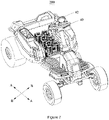
- a center/center of gravity G of the power supply device 30 or a power supply device group including several power supply devices 30 is located between the front axle 111 and the rear axle 121, and a distance S1 between the center/center of gravity G and the rear axle of the rear wheels 122 in direction AA is less than 490 mm.
- This arrangement makes the electric vehicle 100 difficult to roll over.
- the pair of rear wheels 122 are symmetrical about a first axis CC.
- a distance S2 between the center/center of gravity G of the power supply device 30 or the power supply device group including several power supply devices 30 and the first axis BB is not greater than 500 mm.
- a weight ratio of the power supply device 30 or the power supply device group including several power supply devices 30 to the electric vehicle 100 without the power supply device 30 or without the power supply device group is not greater than 0.5.
- the weight ratio of the power supply device 30 or the power supply device group including several power supply devices 30 to the electric vehicle 100 without the power supply device 30 or without the power supply device group is not more than 1/3.
- a distance between a center of gravity of the electric vehicle 100 on which the power supply device 30 is mounted and an axis of the rear wheel 122 in direction AA is not greater than 500 mm.
- the power supply device 30 of the electric vehicle 100 of the disclosure is detachable, it is convenient for users to remove the power supply device 30 for charging the power supply device 30, or use the power supply device 30 as an emergency power source.
- the battery pack 32 since the battery pack 32 is detachably inserted into the charger 31, the battery pack 32 can also be used as a power source for other power tools, or a battery pack of other power tools can be inserted into the charger 31 to become the power source of the electric vehicle 100.
- the power supply device 30 of the electric vehicle 100 of the disclosure can also provide alternating current for emergency use, which meets the user's demand for alternating current outdoors.
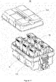
- FIG. 7 shows an electric vehicle 200 according to a second embodiment of the disclosure.
- the structure of the electric vehicle 200 is basically the same as the structure of the electric vehicle 100, the electric vehicle 200 includes the walking mechanism 10, the vehicle body 20, the work apparatus, and the driving mechanism.
- the difference between the electric vehicle 200 and the electric vehicle 100 is that a power supply device 40 of the electric vehicle 200 is different from the power supply device 30 of the electric vehicle 100.
- the power supply device 40 is detachably mounted in the receiving cavity 211 and matches with the power input port to supply power to the electric vehicle 200.
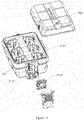
- the power supply device 40 includes a charger 41 and a battery pack 42 matched with the charger 41.
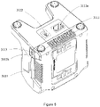
- the charger 41 includes a base 411, a supporting part 412 mounted on the base 411, and a control circuit board.
- the control circuit board integrates an inverter unit (not shown) and a control unit (not shown).
- the base 411 is provided with a power interface 4111, one or more charging portions 4112, and an output part.
- the power interface 4111 is located on a side wall of the base 411 for obtaining external power.
- the charging portion 4112 is arranged on a top of the base 411 and partly around the supporting part 412.
- the charging portion 4112 is provided with a docking interface 4112a connected with the battery pack 42 to obtain power of the battery pack 42 or to charge the battery pack 42.
- the number of the charging portions 4112 is two, and the two charging portions 4112 are located on both sides of the supporting part 412, so that the two charging portions 4112 and the supporting part 412 are collinear in a first direction DD.
- the output part is arranged at a bottom of the base 411 and includes a first power output interface 4113 and a second power output interface (not shown).
- the first power output interface 4113 is used to connect with the power input port to supply power to the electric vehicle 200.
- the output part is arranged at the bottom of the base 411, but in other embodiments, the output part can also be arranged at other positions. For example: a side wall, top wall and so on of the base 411.
- the inverter unit and the control unit are housed in the base 411.
- the inverter unit is used for inverting the power obtained by the docking interface 4112a from the battery pack 42 into alternating current, and outputting the alternating current through the second power output interface.
- the output part may also be provided with a direct current output interface (not shown) to output direct current power.
- the direct current output interface includes one or more of a USB 2.0 interface, a USB 3.0 interface, a Micro USB interface, and a Type-C interface.
- An output voltage of the direct current output interface can be 5V, 20V, etc., which is not limited in the disclosure.
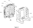
- the base 411 is further provided with a second heat dissipation unit 4114 for dissipating heat for the control circuit board.
- the side wall of the base 411 is further provided with an air inlet 4115 and an air outlet 4116 corresponding to the air inlet 4115.
- the second heat dissipation unit 4114 drives the airflow to flow into the air inlet 4115 and out from the air outlet 4116, so as to dissipate heat of the control circuit board located in the base 411.
- heat sinks (not shown) for auxiliary heat dissipation of the control circuit board is provided in the base 411. Airflow directions of the air inlet 4115 and the air outlet 4116 are parallel to the heat sinks.
- the power interface 4111 includes a first power interface 4111a and a second power interface 4111b.
- the first power interface 4111a is provided at the bottom of the base 411 to connect with the power output port so as to obtain external power through the charging port 215 of the vehicle body 20.
- the second power interface 4111b is arranged on the side wall of the base 411.
- the power supply device 40 is mounted in the receiving cavity 211, the power output port of the vehicle body 20 is directly connected with the first power port 4111a.
- the user takes the power supply device 40 out of the receiving cavity 211, the user can supply power to the charger 41 through the second power interface 4111b.
- the supporting part 412 includes a first wall 4121 facing the battery pack 42, a second wall 4122 located between adjacent charging portions 4112, and a first heat dissipation unit 4123 for heat dissipation of the battery pack 42.
- the first wall 4121 is provided with a first vent 4121a
- the second wall 4122 is provided with a second vent 4122a corresponding to the first vent 4121a.
- the first heat dissipation unit 4123 is mounted in the support part 412, and drives air to flow into one of the first vent 4121a and the second vent 4122a and out from the other one for heat dissipation of the battery pack 42.
- the electric vehicle 200 is usually provided with one or more power supply devices 40.
- the one or more power supply devices 40 are arranged along the forward direction AA of the electric vehicle 200.
- the number of the power supply devices 40 is not more than two in the direction BB perpendicular to the forward direction of the electric vehicle 200.
- the number of the power supply devices 40 is one in the direction BB perpendicular to the forward direction of the electric vehicle 200.
- FIG. 11 shows an electric vehicle 300 according to a third embodiment of the disclosure.
- the structure of the electric vehicle 300 is basically the same as the structure of the electric vehicle 100, including the walking mechanism 10, the vehicle body 20, the work apparatus, and the driving mechanism.
- the difference between the electric vehicle 300 and the electric vehicle 100 is: the power supply device 50 of the electric vehicle 300 is different from the power supply device 30 of the electric vehicle 100.
- the power supply device 50 is detachably mounted in the receiving cavity 211 and matches with the power input port to supply power to the electric vehicle 300.
- the power supply device 50 includes a charger 51 and a battery pack 52 matched with the charger 51.
- the charger 51 includes a base 511, a top cover 512 matched with the base 511, an inverter unit (not shown), and a control unit (not shown).
- the inverter unit and the control unit are housed in the base 511.
- the base 511 is provided with a power interface 5111, one or more charging portions 5112, an air-duct 5113, a ventilation fan 5114, and an output part.
- the power interface 5111 is located on a side wall of the base 511 for obtaining external power.
- the charging portion 5112 is arranged in the base 511, and is provided with a docking interface (not shown) to be connected with the battery pack 52, which is used to obtain the power of the battery pack 52 or charge the battery pack 52.
- the number of the charging portions 5112 is six, and the charging portions are arranged along the forward direction AA of the electric vehicle 300. In addition, in the direction BB perpendicular to the forward direction of the electric vehicle 300, the number of the charging portions 5112 is not more than two.
- the charging portions 5111 are located on both sides of the air-duct 5113, and the air-duct 5113 is arranged along the forward direction AA of the electric vehicle 300 and penetrates the base 511.
- the ventilation fan 5114 is located in the air-duct 5113, and drives the airflow to flow into one end of the air-duct 5113 and flow out from the other end, so as to dissipate heat for the battery pack 52, the inverter unit and the control unit in the charging portion 5112.
- the output part is arranged at the bottom of the base 511 and includes a first power output interface 5115 and a second power output interface (not shown).
- the first power output interface 5115 is used to connect with the power input port to supply power to the electric vehicle 200.
- the inverter unit is used for inverting the power obtained by the docking interface from the battery pack 52 into alternating current, and outputting the alternating current through the second power output interface.
- the output part can also be provided with a direct current output interface (not shown) to output direct current.
- the direct current output interface includes one or more of a USB 2.0 interface, a USB 3.0 interface, a Micro USB interface, and a Type-C interface.
- An output voltage of the direct current output interface can be 5V, 20V, etc., which is not limited in the disclosure.
- the power interface 5111 further includes a first power interface 5111a and a second power interface 5111b.
- the first power interface 5111a is provided at the bottom of the base 511 to be connected with the power output port, so as to facilitate obtaining external power through the charging port 215 of the vehicle body 20.
- the second power interface 5111b is arranged on the side wall of the base 511.
- the control unit obtains information of power of the battery packs, determines discharge priority level of each battery pack according to level of the power, and then controls the battery pack with a highest discharge priority level to discharge.
- the control unit controls the battery pack of the next discharge priority level to discharge together with the currently working battery pack.
- the first preset threshold can be set by the user or the manufacturer as required.
- the control unit obtains information of power of the battery pack, determines charging priority level of each battery pack according to the level of power, and then controls a battery pack with a highest charging priority level to charge. For example, if the power of the battery pack A is lower than the power of the battery pack B, the charging priority level of the battery pack A is higher than the charging priority level of the battery pack B.
- the control unit controls the battery pack of the next charging priority level to charge together with the currently working battery pack.
- the second preset threshold can be set by the user or the manufacturer as required.
Landscapes
- Engineering & Computer Science (AREA)
- Mechanical Engineering (AREA)
- Transportation (AREA)
- Power Engineering (AREA)
- Chemical & Material Sciences (AREA)
- Chemical Kinetics & Catalysis (AREA)
- Electrochemistry (AREA)
- General Chemical & Material Sciences (AREA)
- Manufacturing & Machinery (AREA)
- Life Sciences & Earth Sciences (AREA)
- Combustion & Propulsion (AREA)
- Sustainable Development (AREA)
- Sustainable Energy (AREA)
- Environmental Sciences (AREA)
- Microelectronics & Electronic Packaging (AREA)
- Aviation & Aerospace Engineering (AREA)
- Charge And Discharge Circuits For Batteries Or The Like (AREA)
- Electric Propulsion And Braking For Vehicles (AREA)
Abstract
Description
- The disclosure relates to an electric vehicle.
- The riding mower is a mechanical tool for mowing law and vegetation, which can effectively improve the efficiency of mowing and save a lot of manpower. Since the riding mower can be ridden by the operator, it is convenient for the operator to work on a larger grassland. However, the battery pack and the vehicle body of the existing riding mower are usually arranged as a whole, which makes the battery pack of the riding mower useless except for powering the riding mower. Secondly, when the user is working outdoors, sometimes it is necessary to use other power tools besides the mower. At this time, the user has to carry an extra battery pack that matches the power tool, which brings inconvenience to the user.
- In view of the above problems, it is necessary to provide a new electric vehicle to solve the above problems.
- The disclosure provides an electric vehicle, the electric vehicle is provided with a detachable power supply device, which is convenient for users to remove the power supply device for charging, or use the power supply device as an emergency power supply. At the same time, because the battery pack can be detachably inserted into the charger, the battery pack can also be used as a power source of other power tools, or a battery pack of other power tools can be inserted into the charger to serve as a power source of the electric vehicle.
- The disclosure provides an electric vehicle, the electric vehicle includes a vehicle body provided with a power input port, and a power supply device detachably mounted on the vehicle body. The power supply device supplies power for the electric vehicle and includes a charger and a battery pack that can be detachably inserted into the charger. The charger includes a power interface used to obtain external power, a charging portion provided with a docking interface to connect with the battery pack, an output part used to output power to the outside, and a control unit. The output part includes a first power output interface connected with the power input port to supply power to the electric vehicle. When the power interface is connected with external power, the control unit controls the charging portion to charge the battery pack.
- As a further improvement of the disclosure, the charger is also provided with an inverter unit, the output part further includes a second power output interface, and the inverter unit is used to invert the power obtained by the docking interface from the battery pack into alternating current, and output the alternating current through the second power output interface.
- As a further improvement of the disclosure, the battery pack is detachably connected to a power tool.
- As a further improvement of the disclosure, the vehicle body is provided with a charging port to obtain external power and a power output port electrically connected with the charging port, and when the power supply device is installed on the vehicle body, the power output port is connected with the power interface, at this time, the charger obtains external power through the charging port of the vehicle body and charges the battery pack.
- As a further improvement of the disclosure, the power interface includes a first power interface matched with the power output port and a second power interface to connect with an external power source, the first power interface is arranged on a bottom wall of the charger, and the second power interface is arranged on a side wall of the charger.
- As a further improvement of the disclosure, the charger also includes a base to house the inverter unit and the control unit.
- As a further improvement of the disclosure, the base is located on one side of the charging portion and perpendicular to the charging portion, the charger is also provided with a ventilation fan housed in the base and a ventilation hole arranged on a side wall of the base and matched with the ventilation fan, and the ventilation fan is located at an end of the base away from the charging portion.
- As a further improvement of the disclosure, the base is located on one side of the charging portion and perpendicular to the charging portion, the number of the charging portion is 1, the electric vehicle includes one or more power supply devices, the one or more power supply devices are arranged along a forward direction of the electric vehicle; and in a direction perpendicular to the forward direction of the electric vehicle, the number of the power supply devices is not more than two.
- As a further improvement of the disclosure, the charger further includes a supporting part mounted on the base, the base is provided with one or more charging portions, and the charging portions are arranged around the supporting part, and the inverter unit and the control unit are housed in the base.
- As a further improvement of the disclosure, the support part is provided with a first heat dissipation unit to dissipate heat for the battery pack inserted into the charger.
- As a further improvement of the disclosure, the supporting part includes a first wall facing the battery pack and a second wall located between adjacent charging portions, the first wall is provided with a first vent, and the second wall is provided with a second vent corresponding to the first vent, and the first heat dissipation unit drives airflow to flow into one of the first vent and the second vent, and flow out from the other one of the first vent and the second vent.
- As a further improvement of the disclosure, a second heat dissipation unit to dissipate heat for the inverter unit and the control unit is provided in the base, the base is also provided with an air inlet and an air outlet corresponding to the air inlet, and the second heat dissipation unit drives the airflow to flow into the air inlet and out from the air outlet, so as to dissipate heat for the inverter unit and the control unit.
- As a further improvement of the disclosure, the base is also provided with heat sinks for auxiliary heat dissipation for the inverter unit and the control unit, and an airflow direction of the air inlet and the air outlet is parallel to the heat sinks.
- As a further improvement of the disclosure, the number of the charging portions is two, the two charging portions are respectively located on both sides of the supporting part to allow the two charging portions and the supporting parts to be collinear in a first direction, the electric vehicle includes one or more power supply devices, the one or more power supply devices are arranged along a forward direction of the electric vehicle, wherein, the first direction is parallel to the forward direction of the electric vehicle; and in a direction perpendicular to the forward direction of the electric vehicle, the number of the power supply devices is not more than two.
- As a further improvement of the disclosure, the number of the charging portions is two, the two charging portions are respectively located on both sides of the supporting part to allow the two charging portions and the supporting parts to be collinear in a first direction, the electric vehicle includes one or more power supply devices, the one or more power supply devices are arranged along a forward direction of the electric vehicle, wherein, the first direction is perpendicular to the forward direction of the electric vehicle; and, in the first direction, the number of the power supply device is one.
- As a further improvement of the disclosure, the charger also includes a base, the base is provided with one or more charging portions and a ventilation fan, and the ventilation fan drives airflow to dissipate heat for the charger.
- As a further improvement of the disclosure, the base is also provided with an air-duct, the air-duct is arranged along a forward direction of the electric vehicle, the one or more charging portions are arranged on both sides of the air-duct, and the ventilation fan is located in the air-duct and drives the airflow to flow into one end of the air-duct and flow out from the other end.
- As a further improvement of the disclosure, the control unit obtains information of power of the battery pack, determines a discharge priority level of each battery pack according to level of the power, and then controls the battery pack with a highest discharge priority level to discharge, and when power difference between a current working battery pack and a battery pack of a next discharge priority level is within a first preset threshold, the control unit controls the battery pack of the next discharge priority level to discharge together with the current working battery pack.
- As a further improvement of the disclosure, the electric vehicle includes a walking mechanism, the walking mechanism includes front wheels and rear wheels, and a center/center of gravity of the power supply device or a power supply device group including several power supply devices is located between the front wheels and the rear wheels, and a distance between the center/center of gravity and an axis of the rear wheels is less than 490 mm.
- As a further improvement of the disclosure, the electric vehicle includes a walking mechanism, and the walking mechanism includes a pair of rear wheels, in a forward direction of the electric vehicle, the pair of rear wheels are symmetrical about a first axis, and a horizontal distance between a center/center of gravity of the power supply device or a power supply device group including several power supply devices and the first axis is not greater than 500 mm.
- As a further improvement of the disclosure, a weight ratio of the power supply device or the power supply device group including a plurality of the power supply devices to the electric vehicle without the power supply device or without the power supply device group is not greater than 0.5.
- As a further improvement of the disclosure, the weight ratio of the power supply device or the power supply device group including the plurality of the power supply devices to the electric vehicle without the power supply device or without the power supply device group is not more than 1/3.
- As a further improvement of the disclosure, the electric vehicle further includes a walking mechanism, the walking mechanism includes front wheels and rear wheels, and a distance between a center of gravity of the electric vehicle provided with the power supply device and an axis of the rear wheels is not greater than 500 mm.
- The beneficial effects of the disclosure are: because the power supply device of the electric vehicle of the disclosure is detachable, it is convenient for the user to remove the power supply device for charging, or use the power supply device as an emergency power supply. At the same time, because the battery pack can be detachably inserted into the charger, the battery pack can also be used as a power source of other power tools, or a battery pack of other power tools can be inserted into the charger to become the power source of the electric vehicle.
-
-
FIG. 1 is a perspective schematic view of an electric vehicle according to a first embodiment of the disclosure. -
FIG. 2 is a perspective schematic view of the electric vehicle shown inFIG. 1 in another state. -
FIG. 3 is a perspective schematic view of the electric vehicle shown inFIG. 1 without a seat and power supply device. -
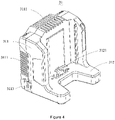
FIG. 4 is a perspective schematic view of a charger of the first embodiment. -
FIG. 5 is a perspective schematic view of the charger shown inFIG. 4 from another angle. -
FIG. 6 is an exploded perspective view of the charger shown inFIG. 4 . -
FIG. 7 is a perspective schematic view of an electric vehicle according to a second embodiment of the disclosure. -
FIG. 8 is a perspective schematic view of a charger of the second embodiment. -
FIG. 9 is a perspective schematic view of the charger shown inFIG. 8 from another angle. -
FIG. 10 is an exploded perspective view of the charger shown inFIG. 8 . -
FIG. 11 is a perspective schematic view of an electric vehicle according to a third embodiment of the disclosure. -
FIG. 12 is a perspective schematic view of a charger of the third embodiment. -
FIG. 13 is a perspective schematic view of the charger shown inFIG. 12 from another angle. -
Fig. 14 is an exploded perspective view of the charger shown inFIG. 12 . - In order to make the purpose, technical solutions and advantages of the disclosure clearer, the disclosure will be described in detail below with reference to the accompanying drawings and specific embodiments.
- Please refer to
FIG. 1 ,FIG. 2 andFIG. 3 . The disclosure provides anelectric vehicle 100, theelectric vehicle 100 can be an electric mower, a golf cart, an all-terrain vehicle, and so on. Theelectric vehicle 100 includes awalking mechanism 10, avehicle body 20 mounted on thewalking mechanism 10, a work apparatus (not shown) mounted on thevehicle body 20 to perform working functions, a driving mechanism (not shown) for driving thewalking mechanism 10 and the work apparatus to work, and apower supply device 30 that provides energy for the driving mechanism. - Please refer to
FIG. 1 andFIG. 2 , thewalking mechanism 10 includes afront wheel assembly 11 and arear wheel assembly 12 arranged opposite to thefront wheel assembly 11. Thefront wheel assembly 11 includes afront axle 111 and a pair offront wheels 112 mounted at both ends of thefront axle 111. Therear wheel assembly 12 includes arear axle 121 parallel to thefront axle 111 and a pair ofrear wheels 122 mounted at both ends of therear axle 121. Thefront axle 111 and therear axle 121 jointly form an axial plane. - Please refer to
FIG. 1 ,FIG. 2 andFIG. 3 , thevehicle body 20 is mounted on thewalking mechanism 10, and includes a base 21 located between thefront axle 111 and therear axle 121 and atail 22 which is on a side of therear axle 121 away from thefront axle 111. Thebase 21 is provided with a receivingcavity 211, aseat 212,pedals 213, an operatingassembly 214, and a power input port (not shown). The receivingcavity 211 is located on a side of the base 21 close to thetail 22 for receiving thepower supply device 30. Theseat 212 is pivotally mounted on one side of the receivingcavity 211 through a pivot (not shown). A shock-absorbingcomponent 2121 is provided on a side of theseat 212 away from the pivot, so as to prevent vibrations generated during a movement of theelectric vehicle 100 from causing discomfort to the user. In this embodiment, the shock-absorbingcomponent 2121 is a spring. Of course, the shock-absorbingcomponent 2121 may also be other forms of parts, which is not limited in the disclosure. When theseat 212 is in a first state (as shown inFIG. 1 ), theseat 212 is located above the receivingcavity 211 and can serve as a cover for the receivingcavity 211 to prevent thepower supply device 30 located in the receivingcavity 211 from being exposed to the outside, so that thepower supply device 30 can be protected. When theseat 212 is rotated and then is transformed from the first state to a second state (as shown inFIG. 2 ), theseat 212 is located on a side of the receivingcavity 211 away from thetail 22. At this time, the receivingcavity 211 is exposed to the outside to facilitate the user to put in or take out thepower supply device 30. Thepedals 213 are located on a side of the receivingcavity 211 away from thetail 22 for the user to step on. When theseat 212 is in the second state, theseat 212 is located above thepedal 213. The operatingassembly 214 is arranged on one side or both sides of theseat 212 for the user to operate. The operating assembly 214 usually includes a brake, a speed control key, an on-off key, etc., which belong to the prior art, and the disclosure will not elaborate on this in detail. The power input port is arranged in the receivingcavity 211 to match with thepower supply device 30 and obtain power from thepower supply device 30, so that the power input port can provide power for the driving mechanism. Thetail 22 is provided with a receivingspace 221 for receiving various parts, tools and so on. The work apparatus is used to perform working functions. The work apparatus may be a cutter assembly mounted on a side of the base 21 facing the ground, or a snow pushing assembly mounted at a front end of the base 21 or the like. The disclosure does not limit the specific functions realized by the work apparatus. The driving mechanism is used to drive thewalking mechanism 10 and the work apparatus to work, and usually includes a first motor (not shown) that drives thewalking mechanism 10 to work and a second motor (not shown) that drives the work apparatus to work(not shown). - Please refer to
FIG. 2 ,FIG. 3 ,FIG. 5 andFIG. 6 , thepower supply device 30 is detachably installed in the receivingcavity 211 and matches with the power input port to supply power to theelectric vehicle 100. Thepower supply device 30 includes acharger 31 and abattery pack 32 matched with thecharger 31. Thecharger 31 includes abase 311, a chargingportion 312 and a circuit board. The circuit board integrates an inverter unit and acontrol unit 313. Thebase 311 is located at one side of the chargingportion 312 and perpendicular to the chargingportion 312. Thebase 311 is provided withseveral ventilation holes 3111, aventilation fan 3112 matched with theventilation holes 3111 and apower interface 3113. Theventilation hole 3111 is arranged on a side wall of thebase 311, and theventilation fan 3112 is arranged in thebase 311. When theventilation fan 3112 works, theventilation fan 3112 drives the air to flow into the base 311 from part of the ventilation holes 3111, flow through the circuit board, and then flow out from the remainingventilation holes 3111, so that heat dissipation of the electronic components on the circuit board can be realized. Thepower interface 3113 is arranged on a side wall of the base 311 to obtain external power. The chargingportion 312 is used to carry thebattery pack 32, and is provided with adocking interface 3121 and an output part. Thedocking interface 3121 is used to connect with thebattery pack 32 to obtain the power in thebattery pack 32 or to charge thebattery pack 32. The output part is arranged at a bottom of the chargingportion 312 to output power to the outside. The output part includes a firstpower output interface 3122 and a second power output interface (not shown). The firstpower output interface 3122 is used to connect with the power input port to supply power to theelectric vehicle 100. The inverter unit and thecontrol unit 313 are housed in thebase 311. The inverter unit is used to invert the power obtained by thedocking interface 3121 from thebattery pack 32 into alternating current, and output the alternating current through the second power output interface. As another embodiment, the chargingportion 312 can also be provided with a direct current output interface (not shown) to output direct current. The direct current output interface includes one or more of a USB 2.0 interface, a USB 3.0 interface, a Micro USB interface, and a Type-C interface. An output voltage of the direct current output interface can be 5V, 20V, etc., which is not limited in the disclosure. - When the
power interface 3113 is connected to external power, thecontrol unit 313 controls the chargingportion 312 to charge thebattery pack 32. When thepower supply device 30 supplies power to theelectric vehicle 100, thedocking interface 3121 obtains power from thebattery pack 32 and supply power to theelectric vehicle 100 through the matching between the firstpower output interface 3122 and the power input port. When other power tools need to use the battery pack, thebattery pack 32 can be removed from thecharger 31, and thebattery pack 32 can be inserted into the power tool to be used. With this arrangement, theelectric vehicle 100 of the disclosure can share thebattery pack 32 with other power tools, which increases the usage rate of thebattery pack 32 and reduces the user's cost and the maintenance cost of the battery pack. - Preferably, the
vehicle body 20 is further provided with a chargingport 215 for obtaining external power and a power output port (not shown) electrically connected with the chargingport 215. The chargingport 215 is arranged on a side of thetail 22 away from thebase 21. Of course, it is understandable that the chargingport 215 can also be arranged in other positions of thevehicle body 20. The disclosure does not limit the location of the chargingport 215. The power output port is arranged in the receivingcavity 211. Thepower interface 3113 includes afirst power interface 3113a and asecond power interface 3113b. Thefirst power interface 3113a is provided at a bottom of the chargingportion 312 to be connected with the power output port so as to obtain external power through the chargingport 215 of thevehicle body 20. Thesecond power interface 3113b is arranged on a side wall of thebase 311. When thepower supply device 30 is mounted in the receivingcavity 211, the power output port is directly connected with thefirst power interface 3113a. Due to the gravity of thepower supply device 30, the connection between thefirst power interface 3113a and the power output port is relatively firm. - In this embodiment, the number of the charging
unit 312 of thepower supply device 30 is one. Please refer toFIG. 2 , theelectric vehicle 100 is usually provided with one or morepower supply devices 30. Preferably, the one or morepower supply devices 30 are arranged along a forward direction of AA of theelectric vehicle 100. And in a direction BB perpendicular to the forward direction of theelectric vehicle 100, the number of thepower supply devices 30 is not more than two. This arrangement can effectively shorten a width of theelectric vehicle 100 in the direction BB. - Preferably, please refer to
FIG. 2 , a center/center of gravity G of thepower supply device 30 or a power supply device group including severalpower supply devices 30 is located between thefront axle 111 and therear axle 121, and a distance S1 between the center/center of gravity G and the rear axle of therear wheels 122 in direction AA is less than 490 mm. This arrangement makes theelectric vehicle 100 difficult to roll over. In the forward direction of theelectric vehicle 100 mentioned above, the pair ofrear wheels 122 are symmetrical about a first axis CC. A distance S2 between the center/center of gravity G of thepower supply device 30 or the power supply device group including severalpower supply devices 30 and the first axis BB is not greater than 500 mm. This arrangement makes theelectric vehicle 100 difficult to roll over from the side. Further, a weight ratio of thepower supply device 30 or the power supply device group including severalpower supply devices 30 to theelectric vehicle 100 without thepower supply device 30 or without the power supply device group is not greater than 0.5. Preferably, the weight ratio of thepower supply device 30 or the power supply device group including severalpower supply devices 30 to theelectric vehicle 100 without thepower supply device 30 or without the power supply device group is not more than 1/3. Further, a distance between a center of gravity of theelectric vehicle 100 on which thepower supply device 30 is mounted and an axis of therear wheel 122 in direction AA is not greater than 500 mm. - The
power supply device 30 of theelectric vehicle 100 of the disclosure is detachable, it is convenient for users to remove thepower supply device 30 for charging thepower supply device 30, or use thepower supply device 30 as an emergency power source. At the same time, since thebattery pack 32 is detachably inserted into thecharger 31, thebattery pack 32 can also be used as a power source for other power tools, or a battery pack of other power tools can be inserted into thecharger 31 to become the power source of theelectric vehicle 100. Secondly, thepower supply device 30 of theelectric vehicle 100 of the disclosure can also provide alternating current for emergency use, which meets the user's demand for alternating current outdoors. -
FIG. 7 shows anelectric vehicle 200 according to a second embodiment of the disclosure. The structure of theelectric vehicle 200 is basically the same as the structure of theelectric vehicle 100, theelectric vehicle 200 includes thewalking mechanism 10, thevehicle body 20, the work apparatus, and the driving mechanism. The difference between theelectric vehicle 200 and theelectric vehicle 100 is that apower supply device 40 of theelectric vehicle 200 is different from thepower supply device 30 of theelectric vehicle 100. Please refer toFIG. 8 ,FIG. 9 ,FIG. 10 andFIG. 7 , thepower supply device 40 is detachably mounted in the receivingcavity 211 and matches with the power input port to supply power to theelectric vehicle 200. Thepower supply device 40 includes acharger 41 and abattery pack 42 matched with thecharger 41. Thecharger 41 includes abase 411, a supportingpart 412 mounted on thebase 411, and a control circuit board. The control circuit board integrates an inverter unit (not shown) and a control unit (not shown). Thebase 411 is provided with apower interface 4111, one ormore charging portions 4112, and an output part. Thepower interface 4111 is located on a side wall of thebase 411 for obtaining external power. The chargingportion 4112 is arranged on a top of thebase 411 and partly around the supportingpart 412. The chargingportion 4112 is provided with adocking interface 4112a connected with thebattery pack 42 to obtain power of thebattery pack 42 or to charge thebattery pack 42. In this embodiment, the number of the chargingportions 4112 is two, and the two chargingportions 4112 are located on both sides of the supportingpart 412, so that the two chargingportions 4112 and the supportingpart 412 are collinear in a first direction DD. The output part is arranged at a bottom of thebase 411 and includes a firstpower output interface 4113 and a second power output interface (not shown). The firstpower output interface 4113 is used to connect with the power input port to supply power to theelectric vehicle 200. In this embodiment, the output part is arranged at the bottom of thebase 411, but in other embodiments, the output part can also be arranged at other positions. For example: a side wall, top wall and so on of thebase 411. The inverter unit and the control unit are housed in thebase 411. The inverter unit is used for inverting the power obtained by thedocking interface 4112a from thebattery pack 42 into alternating current, and outputting the alternating current through the second power output interface. As another embodiment, the output part may also be provided with a direct current output interface (not shown) to output direct current power. The direct current output interface includes one or more of a USB 2.0 interface, a USB 3.0 interface, a Micro USB interface, and a Type-C interface. An output voltage of the direct current output interface can be 5V, 20V, etc., which is not limited in the disclosure. Preferably, thebase 411 is further provided with a secondheat dissipation unit 4114 for dissipating heat for the control circuit board. The side wall of thebase 411 is further provided with anair inlet 4115 and anair outlet 4116 corresponding to theair inlet 4115. The secondheat dissipation unit 4114 drives the airflow to flow into theair inlet 4115 and out from theair outlet 4116, so as to dissipate heat of the control circuit board located in thebase 411. Preferably, heat sinks (not shown) for auxiliary heat dissipation of the control circuit board is provided in thebase 411. Airflow directions of theair inlet 4115 and theair outlet 4116 are parallel to the heat sinks. - Preferably, the
power interface 4111 includes afirst power interface 4111a and asecond power interface 4111b. Thefirst power interface 4111a is provided at the bottom of the base 411 to connect with the power output port so as to obtain external power through the chargingport 215 of thevehicle body 20. Thesecond power interface 4111b is arranged on the side wall of thebase 411. When thepower supply device 40 is mounted in the receivingcavity 211, the power output port of thevehicle body 20 is directly connected with thefirst power port 4111a. When the user takes thepower supply device 40 out of the receivingcavity 211, the user can supply power to thecharger 41 through thesecond power interface 4111b. - Please refer to
FIG. 8 andFIG. 10 , the supportingpart 412 includes afirst wall 4121 facing thebattery pack 42, asecond wall 4122 located between adjacent chargingportions 4112, and a firstheat dissipation unit 4123 for heat dissipation of thebattery pack 42. Thefirst wall 4121 is provided with afirst vent 4121a, and thesecond wall 4122 is provided with asecond vent 4122a corresponding to thefirst vent 4121a. The firstheat dissipation unit 4123 is mounted in thesupport part 412, and drives air to flow into one of thefirst vent 4121a and thesecond vent 4122a and out from the other one for heat dissipation of thebattery pack 42. - Please refer to
FIG. 7 , theelectric vehicle 200 is usually provided with one or morepower supply devices 40. Preferably, the one or morepower supply devices 40 are arranged along the forward direction AA of theelectric vehicle 200. When the first direction DD of thecharger 41 is parallel to the forward direction AA of theelectric vehicle 200, the number of thepower supply devices 40 is not more than two in the direction BB perpendicular to the forward direction of theelectric vehicle 200. When the first direction DD of thecharger 41 is perpendicular to the forward direction AA of theelectric vehicle 200, the number of thepower supply devices 40 is one in the direction BB perpendicular to the forward direction of theelectric vehicle 200. -
FIG. 11 shows anelectric vehicle 300 according to a third embodiment of the disclosure. The structure of theelectric vehicle 300 is basically the same as the structure of theelectric vehicle 100, including thewalking mechanism 10, thevehicle body 20, the work apparatus, and the driving mechanism. The difference between theelectric vehicle 300 and theelectric vehicle 100 is: thepower supply device 50 of theelectric vehicle 300 is different from thepower supply device 30 of theelectric vehicle 100. Please refer toFIG. 12 ,FIG. 13 andFIG. 14 , thepower supply device 50 is detachably mounted in the receivingcavity 211 and matches with the power input port to supply power to theelectric vehicle 300. Thepower supply device 50 includes acharger 51 and abattery pack 52 matched with thecharger 51. Thecharger 51 includes abase 511, atop cover 512 matched with thebase 511, an inverter unit (not shown), and a control unit (not shown). The inverter unit and the control unit are housed in thebase 511. Thebase 511 is provided with apower interface 5111, one ormore charging portions 5112, an air-duct 5113, aventilation fan 5114, and an output part. Thepower interface 5111 is located on a side wall of thebase 511 for obtaining external power. The chargingportion 5112 is arranged in thebase 511, and is provided with a docking interface (not shown) to be connected with thebattery pack 52, which is used to obtain the power of thebattery pack 52 or charge thebattery pack 52. In this embodiment, the number of the chargingportions 5112 is six, and the charging portions are arranged along the forward direction AA of theelectric vehicle 300. In addition, in the direction BB perpendicular to the forward direction of theelectric vehicle 300, the number of the chargingportions 5112 is not more than two. The chargingportions 5111 are located on both sides of the air-duct 5113, and the air-duct 5113 is arranged along the forward direction AA of theelectric vehicle 300 and penetrates thebase 511. Theventilation fan 5114 is located in the air-duct 5113, and drives the airflow to flow into one end of the air-duct 5113 and flow out from the other end, so as to dissipate heat for thebattery pack 52, the inverter unit and the control unit in the chargingportion 5112. The output part is arranged at the bottom of thebase 511 and includes a firstpower output interface 5115 and a second power output interface (not shown). The firstpower output interface 5115 is used to connect with the power input port to supply power to theelectric vehicle 200. The inverter unit is used for inverting the power obtained by the docking interface from thebattery pack 52 into alternating current, and outputting the alternating current through the second power output interface. As another embodiment, the output part can also be provided with a direct current output interface (not shown) to output direct current. The direct current output interface includes one or more of a USB 2.0 interface, a USB 3.0 interface, a Micro USB interface, and a Type-C interface. An output voltage of the direct current output interface can be 5V, 20V, etc., which is not limited in the disclosure. - Preferably, the
power interface 5111 further includes afirst power interface 5111a and asecond power interface 5111b. Thefirst power interface 5111a is provided at the bottom of the base 511 to be connected with the power output port, so as to facilitate obtaining external power through the chargingport 215 of thevehicle body 20. Thesecond power interface 5111b is arranged on the side wall of thebase 511. - Since there are multiple battery packs in the
power supply device 40 and thepower supply device 50. Preferably, the control unit obtains information of power of the battery packs, determines discharge priority level of each battery pack according to level of the power, and then controls the battery pack with a highest discharge priority level to discharge. When power difference between a currently working battery pack and a battery pack corresponding to a next discharge priority level is within a first preset threshold, the control unit controls the battery pack of the next discharge priority level to discharge together with the currently working battery pack. The first preset threshold can be set by the user or the manufacturer as required. - When the
power supply device 40 and thepower supply device 50 are in a charging state, the control unit obtains information of power of the battery pack, determines charging priority level of each battery pack according to the level of power, and then controls a battery pack with a highest charging priority level to charge. For example, if the power of the battery pack A is lower than the power of the battery pack B, the charging priority level of the battery pack A is higher than the charging priority level of the battery pack B. When power difference between a currently working battery pack and a battery pack corresponding to a next charging priority level is within a second preset threshold, the control unit controls the battery pack of the next charging priority level to charge together with the currently working battery pack. The second preset threshold can be set by the user or the manufacturer as required. - The above embodiments are only used to illustrate the technical solution of the disclosure and not to limit it. Although the disclosure is described in detail with reference to the preferred embodiments, those of ordinary skill in the art should understand that the technical solution of the disclosure can be modified or replaced without departing from the spirit and scope of the technical solution of the disclosure.
Claims (15)
- An electric vehicle (100, 200), comprising:a vehicle body (20), provided with a power input port; anda power supply device (30, 40, 50), detachably mounted on the vehicle body (20), the power supply device (30, 40, 50) supplying power for the electric vehicle (100) and comprising a charger (31, 41, 51) and a battery pack (32,42,52) capable of detachably inserting into the charger (31, 41, 51),
wherein the charger (31, 41, 51) comprises:a power interface (3113, 4111, 5111), used to obtain external power,a charging portion (312, 4112, 5112), provided with a docking interface (3121, 4112a) to connect with the battery pack,an output part, used to output power to the outside, the output part comprising a first power output interface (3122, 4113, 5115) connected with the power input port to supply power to the electric vehicle (100), anda control unit,wherein when the power interface (3113, 4111, 5111) is connected with external power, the control unit controls the charging portion (312, 4112, 5112) to charge the battery pack. - The electric vehicle (100, 200) according to any proceeding claim, whereinthe charger (31, 41, 51) is further provided with an inverter unit, the output part further comprises a second power output interface, and the inverter unit is used to invert the power obtained by the docking interface (3121, 4112a) from the battery pack (32,42,52) into alternating current, and output the alternating current through the second power output interface;the charger (31, 41, 51) further comprises a base (311, 411, 511) to house the inverter unit and the control unit.
- The electric vehicle (100, 200) according to any proceeding claim, wherein the battery pack (32,42,52) is detachably connected to a power tool.
- The electric vehicle (100, 200) according to any proceeding claim, whereinthe vehicle body (20) is provided with a charging port to obtain external power and a power output port electrically connected with the charging port, and when the power supply device is installed on the vehicle body (20), the power output port is connected with the power interface (3113, 4111, 5111), at this time, the charger (31, 41, 51) obtains external power through the charging port of the vehicle body (20) and charges the battery pack (32,42,52);the power interface (3113, 4111, 5111) comprises a first power interface (3111a, 4111a, 5111a) matched with the power output port and a second power interface (3111b, 4111b, 5111b) to connect with an external power source, the first power interface (3111a, 4111a, 5111a) is arranged on a bottom wall of the charger (31, 41, 51), and the second power interface (3111b, 4111b, 5111b) is arranged on a side wall of the charger.
- The electric vehicle (100, 200) according to claim 2, wherein
the base (311, 411, 511) is located on one side of the charging portion and perpendicular to the charging portion (312, 4112, 5112); the charger is further provided with a ventilation fan (3112, 4114, 5114) housed in the base, and a ventilation hole (3111,4116,) arranged on a side wall of the base and matched with the ventilation fan; and the ventilation fan is located at an end of the base (311, 411, 511) away from the charging portion (312, 4112, 5112). - The electric vehicle (100, 200) according to claim 2, wherein
the base (311, 411, 511) is located on one side of the charging portion (312, 4112, 5112) and perpendicular to the charging portion, the number of the charging portion is 1, the electric vehicle (100,200) comprises one or more power supply devices, the one or more power supply devices are arranged along a forward direction (AA) of the electric vehicle; and in a direction (BB) perpendicular to the forward direction of the electric vehicle, the number of the power supply devices is not more than two. - The electric vehicle (100, 200) according to claim 2, whereinthe charger (31, 41, 51) further comprises a supporting part (412) mounted on the base, the base is provided with one or more charging portions; and the charging portions are arranged around the supporting part; and the inverter unit and the control unit are housed in the base;the support part is provided with a first heat dissipation unit for heat dissipation of the battery pack inserted into the charger.
- The electric vehicle (100, 200) according to claim 7, whereinthe supporting part (412) comprises a first wall (4121) facing the battery pack and a second wall (4122) located between adjacent charging portions, the first wall is provided with a first vent (4121a), and the second wall is provided with a second vent (4122a) corresponding to the first vent; and the first heat dissipation unit (4123) drives airflow to flow into one of the first vent and the second vent, and flow out from the other one; anda second heat dissipation unit (4114) for heat dissipation of the inverter unit and the control unit is provided in the base, the base (411) is further provided with an air inlet (4115) and an air outlet (4116) corresponding to the air inlet, and the second heat dissipation unit (4114) drives the airflow to flow into the air inlet and out from the air outlet, so as to dissipate heat for the inverter unit and the control unit.
- The electric vehicle (100, 200) according to claim 8, wherein
the base is further provided with heat sinks for auxiliary heat dissipation for the inverter unit and the control unit, and an airflow direction of the air inlet and the air outlet is parallel to the heat sinks. - The electric vehicle (100, 200) according to claim 7, wherein
the number of the charging portions is two, the two charging portions are respectively located on both sides of the supporting part to allow the two charging portions and the supporting parts to be collinear in a first direction, the electric vehicle comprises one or more power supply devices, the one or more power supply devices are arranged along a forward direction (AA) of the electric vehicle, wherein, the first direction is parallel to the forward direction of the electric vehicle; and in a direction (BB) perpendicular to the forward direction of the electric vehicle, the number of the power supply devices is not more than two. - The electric vehicle (100, 200) according to claim 7, wherein
the number of the charging portions is two, the two charging portions are respectively located on both sides of the supporting part to allow the two charging portions and the supporting parts to be collinear in a first direction, the electric vehicle comprises one or more power supply devices, the one or more power supply devices are arranged along a forward direction of the electric vehicle, wherein, the first direction is perpendicular to the forward direction of the electric vehicle; and, in the first direction, the number of the power supply device is one. - The electric vehicle (100, 200) according to any proceeding claim, whereinthe charger further comprises a base, the base is provided with one or more charging portions and a ventilation fan, and the ventilation fan drives airflow to dissipate heat for the charger; andthe base is further provided with an air-duct, the air-duct is arranged along a forward direction of the electric vehicle, the one or more charging portions are arranged on both sides of the air-duct, and the ventilation fan is located in the air-duct and drives the airflow to flow into one end of the air-duct and flow out from the other end.
- The electric vehicle (100, 200) according to any proceeding claim, further comprising a walking mechanism (10), whereinthe walking mechanism comprises front wheels (11) and rear wheels (12), and a center/center of gravity of the power supply device or a power supply device group comprising a plurality of the power supply devices is located between the front wheels and the rear wheels, and a distance (S1) between the center/center of gravity and an axis (121) of the rear wheels (12) is less than 490 mm;the walking mechanism (10) comprises a pair of rear wheels (12), in a forward direction of the electric vehicle, the pair of rear wheels (12) are symmetrical about a first axis (CC), and a horizontal distance (S2) between a center/center of gravity of the power supply device or a power supply device group comprising a plurality of the power supply devices and the first axis (CC) is not greater than 500 mm.
- The electric vehicle (100, 200) according to any proceeding claim, whereina weight ratio of the power supply device or the power supply device group comprising a plurality of the power supply devices to the electric vehicle without the power supply device or without the power supply device group is not greater than 0.5;the weight ratio of the power supply device or the power supply device group comprising the plurality of the power supply devices to the electric vehicle without the power supply device or without the power supply device group is not more than 1/3.
- The electric vehicle (100, 200) according to any proceeding claim, further comprising a walking mechanism (10), wherein
the walking mechanism comprises front wheels (11) and rear wheels (12), and a distance (S1) between a center of gravity of the electric vehicle with the power supply device and an axis of the rear wheels (121) is not greater than 500 mm.
Applications Claiming Priority (1)
| Application Number | Priority Date | Filing Date | Title |
|---|---|---|---|
| CN202011550948.6A CN112706602A (en) | 2020-12-24 | 2020-12-24 | Electric vehicle |
Publications (1)
| Publication Number | Publication Date |
|---|---|
| EP4046860A1 true EP4046860A1 (en) | 2022-08-24 |
Family
ID=75544289
Family Applications (1)
| Application Number | Title | Priority Date | Filing Date |
|---|---|---|---|
| EP21215201.1A Pending EP4046860A1 (en) | 2020-12-24 | 2021-12-16 | Electric vehicle |
Country Status (4)
| Country | Link |
|---|---|
| US (2) | US12208668B2 (en) |
| EP (1) | EP4046860A1 (en) |
| CN (1) | CN112706602A (en) |
| AU (1) | AU2021286306A1 (en) |
Families Citing this family (15)
| Publication number | Priority date | Publication date | Assignee | Title |
|---|---|---|---|---|
| US20230147651A1 (en) * | 2020-03-23 | 2023-05-11 | Techtronic Cordless Gp | Multi-battery management for a portable device |
| US12296694B2 (en) | 2021-03-10 | 2025-05-13 | Techtronic Cordless Gp | Lawnmowers |
| MX2023014849A (en) * | 2021-06-16 | 2024-06-11 | Globe Jiangsu Co Ltd | Mower. |
| USD1042223S1 (en) * | 2021-12-24 | 2024-09-17 | Hyundai Motor Company | Personal mobility |
| CN116418066A (en) * | 2021-12-30 | 2023-07-11 | 南京泉峰科技有限公司 | Charger (charger) |
| USD1015381S1 (en) | 2022-02-14 | 2024-02-20 | Techtronic Cordless Gp | Lawn mower |
| USD1014568S1 (en) | 2022-02-14 | 2024-02-13 | Techtronic Cordless Gp | Lawn mower |
| WO2024064793A1 (en) * | 2022-09-21 | 2024-03-28 | Ariens Company | Removable battery storage for outdoor power equipment |
| CN120265122A (en) * | 2022-10-13 | 2025-07-04 | 布里格斯斯特拉顿有限责任公司 | Electrified chore products with integrated on-board charger |
| CN116034715A (en) * | 2022-12-05 | 2023-05-02 | 浙江亚特电器股份有限公司 | A riding lawn mower |
| WO2024125035A1 (en) * | 2022-12-15 | 2024-06-20 | 南京泉峰科技有限公司 | Electric all-terrain vehicle |
| JP2024114021A (en) * | 2023-02-10 | 2024-08-23 | 株式会社豊田自動織機 | Industrial Vehicles |
| CN118542152A (en) * | 2023-02-24 | 2024-08-27 | 南京泉峰科技有限公司 | Outdoor work vehicle |
| US12520461B2 (en) * | 2023-03-24 | 2026-01-06 | Livewire Ev, Llc | Power electronics module for electric vehicle |
| WO2024074044A1 (en) * | 2023-05-19 | 2024-04-11 | 皖西学院 | Hybrid energy storage system apparatus for power supply of battery electric vehicle |
Citations (5)
| Publication number | Priority date | Publication date | Assignee | Title |
|---|---|---|---|---|
| CA3107893A1 (en) * | 2018-08-01 | 2020-02-06 | Nanjing Chervon Industry Co., Ltd. | Riding lawn mower, and current-limiting protection method for same |
| CN210092928U (en) * | 2019-08-01 | 2020-02-18 | 常州格力博有限公司 | Charging device |
| CN111296044A (en) * | 2020-03-26 | 2020-06-19 | 常州格力博有限公司 | Mower and battery management system |
| CN111492783A (en) * | 2019-01-30 | 2020-08-07 | 南京德朔实业有限公司 | Riding type lawn nursing vehicle |
| US20200315095A1 (en) * | 2017-12-28 | 2020-10-08 | Nanjing Chervon Industry Co., Ltd. | Electric riding lawn mower |
Family Cites Families (15)
| Publication number | Priority date | Publication date | Assignee | Title |
|---|---|---|---|---|
| US8653786B2 (en) * | 2008-04-25 | 2014-02-18 | Black & Decker Inc. | Cordless mower including battery with two charging connectors |
| US9016412B2 (en) * | 2013-08-30 | 2015-04-28 | Ford Global Technologies, Llc | Duct to influence air cooling distribution to battery module and DC/DC module |
| CN104752655B (en) * | 2013-12-31 | 2017-12-29 | 南京德朔实业有限公司 | Battery bag, charger and charging combination |
| CN105794411B (en) * | 2014-12-30 | 2020-04-07 | 南京德朔实业有限公司 | Power tool |
| CN205901380U (en) * | 2016-08-05 | 2017-01-18 | 常州格力博有限公司 | Charger |
| CN108819747B (en) * | 2018-06-13 | 2021-11-02 | 蔚来(安徽)控股有限公司 | Multi-branch power distribution management of multi-branch energy storage system |
| CN209298226U (en) * | 2018-10-10 | 2019-08-23 | 深圳乐行运动科技有限公司 | Battery component and electronic equipment |
| CN109941149B (en) * | 2019-04-12 | 2021-08-20 | 爱驰汽车有限公司 | Multi-source battery pack charging and discharging method and device, electronic equipment and storage medium |
| CN210694954U (en) * | 2019-06-26 | 2020-06-09 | 苏州金莱克精密机械有限公司 | a lawn mower |
| CN210092927U (en) * | 2019-08-01 | 2020-02-18 | 常州格力博有限公司 | Charging device |
| CN111123910B (en) * | 2019-11-15 | 2023-04-14 | 苏州博迷科技有限公司 | A dual-core four-wheel drive UWB positioning mowing robot and its control method |
| CN110696958A (en) * | 2019-11-21 | 2020-01-17 | 常州格力博有限公司 | Riding type electric tool |
| CN211353152U (en) * | 2019-12-05 | 2020-08-28 | 格力博(江苏)股份有限公司 | Lawn mower and battery pack assembly |
| CN111509804A (en) * | 2020-04-27 | 2020-08-07 | 格力博(江苏)股份有限公司 | Charger, mower and charging control method |
| CN111262311A (en) * | 2020-03-27 | 2020-06-09 | 常州格力博有限公司 | Charger, mower and charging control method |
-
2020
- 2020-12-24 CN CN202011550948.6A patent/CN112706602A/en active Pending
-
2021
- 2021-12-14 AU AU2021286306A patent/AU2021286306A1/en active Pending
- 2021-12-14 US US17/551,125 patent/US12208668B2/en active Active
- 2021-12-16 EP EP21215201.1A patent/EP4046860A1/en active Pending
-
2024
- 2024-12-22 US US18/991,665 patent/US20250121670A1/en active Pending
Patent Citations (5)
| Publication number | Priority date | Publication date | Assignee | Title |
|---|---|---|---|---|
| US20200315095A1 (en) * | 2017-12-28 | 2020-10-08 | Nanjing Chervon Industry Co., Ltd. | Electric riding lawn mower |
| CA3107893A1 (en) * | 2018-08-01 | 2020-02-06 | Nanjing Chervon Industry Co., Ltd. | Riding lawn mower, and current-limiting protection method for same |
| CN111492783A (en) * | 2019-01-30 | 2020-08-07 | 南京德朔实业有限公司 | Riding type lawn nursing vehicle |
| CN210092928U (en) * | 2019-08-01 | 2020-02-18 | 常州格力博有限公司 | Charging device |
| CN111296044A (en) * | 2020-03-26 | 2020-06-19 | 常州格力博有限公司 | Mower and battery management system |
Also Published As
| Publication number | Publication date |
|---|---|
| US20250121670A1 (en) | 2025-04-17 |
| US20220203816A1 (en) | 2022-06-30 |
| AU2021286306A1 (en) | 2022-07-14 |
| CN112706602A (en) | 2021-04-27 |
| US12208668B2 (en) | 2025-01-28 |
Similar Documents
| Publication | Publication Date | Title |
|---|---|---|
| US12208668B2 (en) | Electric vehicle | |
| JP2014147353A (en) | Electric lawn mower | |
| CN204045695U (en) | power supply unit | |
| WO2017211324A1 (en) | Adapter, portable power system, and power system | |
| CN110768320A (en) | Adapters and Portable Power Supplies | |
| US20240090374A1 (en) | Power tool | |
| GB2419557A (en) | Hand held sanding power tool | |
| US20250055111A1 (en) | Electrical device, electrical system, and battery pack | |
| CN213471501U (en) | Circular saw | |
| CN216564567U (en) | Adapter, portable power source and electric tool | |
| EP4032672A2 (en) | Chain saw | |
| JP7062532B2 (en) | Cleaner | |
| CN113782862A (en) | Cordless Power Tools | |
| CN210668504U (en) | New energy automobile battery box | |
| WO2024055971A1 (en) | Power head and power system | |
| WO2020216287A1 (en) | Long-rod type grinding machine | |
| CN218241955U (en) | Cordless Power Tools | |
| GB2419559A (en) | Sanding soleplate for a hand held sander | |
| CN118542152A (en) | Outdoor work vehicle | |
| JPH08241730A (en) | Rechargeable battery | |
| WO2025139860A1 (en) | Outdoor garden lawn mower, energy source system, and outdoor work device | |
| CN218850447U (en) | Portable power source with wind channel heat dissipation | |
| CN223584562U (en) | Power management devices with heat dissipation function and outdoor work vehicles | |
| GB2419558A (en) | Hand held sanding tool with pressure switch | |
| EP4683158A1 (en) | Holding device |
Legal Events
| Date | Code | Title | Description |
|---|---|---|---|
| PUAI | Public reference made under article 153(3) epc to a published international application that has entered the european phase |
Free format text: ORIGINAL CODE: 0009012 |
|
| STAA | Information on the status of an ep patent application or granted ep patent |
Free format text: STATUS: THE APPLICATION HAS BEEN PUBLISHED |
|
| AK | Designated contracting states |
Kind code of ref document: A1 Designated state(s): AL AT BE BG CH CY CZ DE DK EE ES FI FR GB GR HR HU IE IS IT LI LT LU LV MC MK MT NL NO PL PT RO RS SE SI SK SM TR |
|
| STAA | Information on the status of an ep patent application or granted ep patent |
Free format text: STATUS: REQUEST FOR EXAMINATION WAS MADE |
|
| 17P | Request for examination filed |
Effective date: 20230117 |
|
| RBV | Designated contracting states (corrected) |
Designated state(s): AL AT BE BG CH CY CZ DE DK EE ES FI FR GB GR HR HU IE IS IT LI LT LU LV MC MK MT NL NO PL PT RO RS SE SI SK SM TR |