EP4046818A1 - Wheel hub for mounting a wheel on an axle of a work vehicle - Google Patents
Wheel hub for mounting a wheel on an axle of a work vehicle Download PDFInfo
- Publication number
- EP4046818A1 EP4046818A1 EP20877764.9A EP20877764A EP4046818A1 EP 4046818 A1 EP4046818 A1 EP 4046818A1 EP 20877764 A EP20877764 A EP 20877764A EP 4046818 A1 EP4046818 A1 EP 4046818A1
- Authority
- EP
- European Patent Office
- Prior art keywords
- sleeve
- wheel hub
- axle
- planetary gearbox
- wheel
- Prior art date
- Legal status (The legal status is an assumption and is not a legal conclusion. Google has not performed a legal analysis and makes no representation as to the accuracy of the status listed.)
- Granted
Links
Images
Classifications
-
- F—MECHANICAL ENGINEERING; LIGHTING; HEATING; WEAPONS; BLASTING
- F16—ENGINEERING ELEMENTS AND UNITS; GENERAL MEASURES FOR PRODUCING AND MAINTAINING EFFECTIVE FUNCTIONING OF MACHINES OR INSTALLATIONS; THERMAL INSULATION IN GENERAL
- F16H—GEARING
- F16H63/00—Control outputs from the control unit to change-speed- or reversing-gearings for conveying rotary motion or to other devices than the final output mechanism
- F16H63/02—Final output mechanisms therefor; Actuating means for the final output mechanisms
- F16H63/30—Constructional features of the final output mechanisms
- F16H63/3023—Constructional features of the final output mechanisms the final output mechanisms comprising elements moved by fluid pressure
-
- B—PERFORMING OPERATIONS; TRANSPORTING
- B60—VEHICLES IN GENERAL
- B60B—VEHICLE WHEELS; CASTORS; AXLES FOR WHEELS OR CASTORS; INCREASING WHEEL ADHESION
- B60B27/00—Hubs
- B60B27/02—Hubs adapted to be rotatably arranged on axle
- B60B27/04—Hubs adapted to be rotatably arranged on axle housing driving means, e.g. sprockets
-
- B—PERFORMING OPERATIONS; TRANSPORTING
- B60—VEHICLES IN GENERAL
- B60K—ARRANGEMENT OR MOUNTING OF PROPULSION UNITS OR OF TRANSMISSIONS IN VEHICLES; ARRANGEMENT OR MOUNTING OF PLURAL DIVERSE PRIME-MOVERS IN VEHICLES; AUXILIARY DRIVES FOR VEHICLES; INSTRUMENTATION OR DASHBOARDS FOR VEHICLES; ARRANGEMENTS IN CONNECTION WITH COOLING, AIR INTAKE, GAS EXHAUST OR FUEL SUPPLY OF PROPULSION UNITS IN VEHICLES
- B60K17/00—Arrangement or mounting of transmissions in vehicles
- B60K17/04—Arrangement or mounting of transmissions in vehicles characterised by arrangement, location or kind of gearing
- B60K17/043—Transmission unit disposed in on near the vehicle wheel, or between the differential gear unit and the wheel
- B60K17/046—Transmission unit disposed in on near the vehicle wheel, or between the differential gear unit and the wheel with planetary gearing having orbital motion
-
- F—MECHANICAL ENGINEERING; LIGHTING; HEATING; WEAPONS; BLASTING
- F16—ENGINEERING ELEMENTS AND UNITS; GENERAL MEASURES FOR PRODUCING AND MAINTAINING EFFECTIVE FUNCTIONING OF MACHINES OR INSTALLATIONS; THERMAL INSULATION IN GENERAL
- F16H—GEARING
- F16H3/00—Toothed gearings for conveying rotary motion with variable gear ratio or for reversing rotary motion
- F16H3/44—Toothed gearings for conveying rotary motion with variable gear ratio or for reversing rotary motion using gears having orbital motion
- F16H3/46—Gearings having only two central gears, connected by orbital gears
- F16H3/48—Gearings having only two central gears, connected by orbital gears with single orbital gears or pairs of rigidly-connected orbital gears
- F16H3/50—Gearings having only two central gears, connected by orbital gears with single orbital gears or pairs of rigidly-connected orbital gears comprising orbital conical gears
-
- B—PERFORMING OPERATIONS; TRANSPORTING
- B60—VEHICLES IN GENERAL
- B60Y—INDEXING SCHEME RELATING TO ASPECTS CROSS-CUTTING VEHICLE TECHNOLOGY
- B60Y2200/00—Type of vehicle
- B60Y2200/10—Road Vehicles
- B60Y2200/14—Trucks; Load vehicles, Busses
- B60Y2200/142—Heavy duty trucks
-
- F—MECHANICAL ENGINEERING; LIGHTING; HEATING; WEAPONS; BLASTING
- F16—ENGINEERING ELEMENTS AND UNITS; GENERAL MEASURES FOR PRODUCING AND MAINTAINING EFFECTIVE FUNCTIONING OF MACHINES OR INSTALLATIONS; THERMAL INSULATION IN GENERAL
- F16D—COUPLINGS FOR TRANSMITTING ROTATION; CLUTCHES; BRAKES
- F16D25/00—Fluid-actuated clutches
- F16D25/06—Fluid-actuated clutches in which the fluid actuates a piston incorporated in, i.e. rotating with the clutch
- F16D25/061—Fluid-actuated clutches in which the fluid actuates a piston incorporated in, i.e. rotating with the clutch the clutch having interengaging clutch members
-
- F—MECHANICAL ENGINEERING; LIGHTING; HEATING; WEAPONS; BLASTING
- F16—ENGINEERING ELEMENTS AND UNITS; GENERAL MEASURES FOR PRODUCING AND MAINTAINING EFFECTIVE FUNCTIONING OF MACHINES OR INSTALLATIONS; THERMAL INSULATION IN GENERAL
- F16H—GEARING
- F16H63/00—Control outputs from the control unit to change-speed- or reversing-gearings for conveying rotary motion or to other devices than the final output mechanism
- F16H63/02—Final output mechanisms therefor; Actuating means for the final output mechanisms
- F16H63/30—Constructional features of the final output mechanisms
- F16H2063/3093—Final output elements, i.e. the final elements to establish gear ratio, e.g. coupling sleeves or other means establishing coupling to shaft
- F16H2063/3096—Sliding keys as final output elements; Details thereof
-
- F—MECHANICAL ENGINEERING; LIGHTING; HEATING; WEAPONS; BLASTING
- F16—ENGINEERING ELEMENTS AND UNITS; GENERAL MEASURES FOR PRODUCING AND MAINTAINING EFFECTIVE FUNCTIONING OF MACHINES OR INSTALLATIONS; THERMAL INSULATION IN GENERAL
- F16H—GEARING
- F16H2200/00—Transmissions for multiple ratios
- F16H2200/20—Transmissions using gears with orbital motion
- F16H2200/2002—Transmissions using gears with orbital motion characterised by the number of sets of orbital gears
- F16H2200/2005—Transmissions using gears with orbital motion characterised by the number of sets of orbital gears with one sets of orbital gears
-
- F—MECHANICAL ENGINEERING; LIGHTING; HEATING; WEAPONS; BLASTING
- F16—ENGINEERING ELEMENTS AND UNITS; GENERAL MEASURES FOR PRODUCING AND MAINTAINING EFFECTIVE FUNCTIONING OF MACHINES OR INSTALLATIONS; THERMAL INSULATION IN GENERAL
- F16H—GEARING
- F16H2200/00—Transmissions for multiple ratios
- F16H2200/20—Transmissions using gears with orbital motion
- F16H2200/203—Transmissions using gears with orbital motion characterised by the engaging friction means not of the freewheel type, e.g. friction clutches or brakes
- F16H2200/2033—Transmissions using gears with orbital motion characterised by the engaging friction means not of the freewheel type, e.g. friction clutches or brakes with one engaging means
-
- F—MECHANICAL ENGINEERING; LIGHTING; HEATING; WEAPONS; BLASTING
- F16—ENGINEERING ELEMENTS AND UNITS; GENERAL MEASURES FOR PRODUCING AND MAINTAINING EFFECTIVE FUNCTIONING OF MACHINES OR INSTALLATIONS; THERMAL INSULATION IN GENERAL
- F16H—GEARING
- F16H2200/00—Transmissions for multiple ratios
- F16H2200/20—Transmissions using gears with orbital motion
- F16H2200/203—Transmissions using gears with orbital motion characterised by the engaging friction means not of the freewheel type, e.g. friction clutches or brakes
- F16H2200/2064—Transmissions using gears with orbital motion characterised by the engaging friction means not of the freewheel type, e.g. friction clutches or brakes using at least one positive clutch, e.g. dog clutch
-
- F—MECHANICAL ENGINEERING; LIGHTING; HEATING; WEAPONS; BLASTING
- F16—ENGINEERING ELEMENTS AND UNITS; GENERAL MEASURES FOR PRODUCING AND MAINTAINING EFFECTIVE FUNCTIONING OF MACHINES OR INSTALLATIONS; THERMAL INSULATION IN GENERAL
- F16H—GEARING
- F16H2200/00—Transmissions for multiple ratios
- F16H2200/20—Transmissions using gears with orbital motion
- F16H2200/2094—Transmissions using gears with orbital motion using positive clutches, e.g. dog clutches
Definitions
- the present invention relates to wheel hubs of a work vehicle, specifically, to a reduction system for a wheel hub.
- a work vehicle such as a large truck, generally includes a chassis, a suspension system, an engine to provide a driving force, a transmission, and a drive train, which includes at least three axles with wheels attached.
- the work vehicle may include a front steering axle and a pair of rear tandem axles to increase the load bearing and towing capacity of the work vehicle.
- the work vehicle drive train may include multiple clutches to drive one or more rear axles and gearboxes to provide one or more speed reductions between the engine and the wheels.
- the drive train of the work vehicle may have multiple traction, i.e. drive configurations, such as a 6x2, 6x4, 6x6, 8x4, 8x8 or 10x8 drive configuration, due to the various clutches that selectively (dis)connect the driving force to the axles.
- a work vehicle with a 6x4 drive configuration may include an undriven steerable front axle and a pair of rear tandem or individual axles. Therefore, when the work vehicle is towing a payload, such as a semi-trailer loaded with goods, both rear axles can be driven to increase the towing capabilities of a work vehicle, and when the work vehicle is on a return trip with no payload, only one of the rear axles can be driven to increase fuel economy. Additionally, in other circumstances, for example when towing a heavy load uphill, it may be desirable to provide a driving force to all three axles of the work vehicle in a 6x6 drive configuration to increase traction.
- the work vehicle may also provide one or more speed reductions between the engine and the wheels in order to reduce wheel speed and increase engine torque.
- a reduction system may be provided for each wheel hub of the respective axle.
- the reduction system may include a planetary gearbox operably connected between the differential drive axle and the wheel hub.
- the reduction ratio between the drive axle and the wheel hub is fixed, for example at a 2:1 reduction.
- some reduction systems include a selectively engaging planetary gearbox that allows full disengagement as well as a variable reduction ratio.
- Document WO 2016/110823 describes a wheel hub reduction system with a single piston and a sliding sleeve for selectively engaging a planetary gearbox with the wheel hub in two indexed positions, which results in a reduction ratio of 2:1 or 1:1 between the drive axle and the wheel hub. In this way, the speed reduction at the wheels can be appropriately matched with the loading of the work vehicle.
- WO 2018/107258 describes a reduction system with a two-piston system and a sliding sleeve for selectively engaging and disengaging a planetary gearbox to/from the wheel hub.
- the reduction system can completely disengage the driving force from the wheel hub and provides a reduction ratio of 2:1 or 1:1. In this way, the reduction system can accommodate a wider spectrum of operating positions, and the full disengagement position can substantially increase the work vehicle's fuel economy.
- the two-piston system can increase manufacturing and operating costs.
- an integrated reduction system is provided within the wheel hub of a work vehicle.
- the reduction system includes a planetary gearbox configured to be operably connected between the axle and the wheel, the sleeve configured to slidably connect to the axle, and an actuation device connected to the sleeve and configured to slide the sleeve.
- the reduction system provides an operating position for reducing speed and increasing traction on the wheels, and an operating position for disengaging or completely releasing the traction wheels.
- a wheel hub for mounting a wheel on an axle of a work vehicle.
- the wheel hub includes a housing with a side end cap and a reduction system.
- the reduction system includes a planetary gearbox configured to be operably connected between the axle and the wheel, a sleeve configured to slidably connect to the axle, and an actuation device connected to the sleeve and configured to slide the sleeve.
- the reduction system has a first operating position in which the sleeve engages with the planetary gearbox to transmit the driving force from the axle at a speed reduction ratio, and a second operating position in which the sleeve disengages from the planetary gearbox to cease transmitting the driving force from the axle so as to release the wheel.
- a possible advantage of this embodiment of the work vehicle is that the reduction system can accommodate various drive conditions of the work vehicle to selectively increase or decrease wheel torque and traction.
- a further possible advantage of the embodiment of the work vehicle is that the reduction system can substantially increase the fuel economy of the work vehicle by completely releasing the traction wheels.
- front used in connection with a vehicle and/or components thereof are generally determined with reference to the forward direction of travel of a vehicle and are not to be construed as limiting.
- longitudinal and “transverse” are determined with reference to the forward and rearward direction of the vehicle and are not to be construed as limiting.
- a work vehicle 10 typically includes a chassis 12, a cab 14 for an operator, a main engine 16, for example, a diesel engine 16, a front axle 18, a rear axle assembly 20 with at least two axles 22, 24, wheels 26 attached to the axles 18, 22, 24, and a drive system including a transmission, that accompanies a gearbox(es), and a main drive axle 28 for transmitting driving force, i.e., drive torque, from the engine 16 to the rear axle assembly 20 to provide primary traction for the work vehicle 10.
- the front wheels 26 of the front axle 18 are normally configured to be steered to provide directional control for the work vehicle 10.
- the engine 16, via the transmission system, may drive the wheels 26 of any axle 18, 22, 24.
- the work vehicle 10 may have any desired drive configuration, such as a 4x2, 6x6, 6x4, 6x2, 8x8, 8x4, or 10x6 drive configuration.
- the work vehicle 10 may be in the form of any desired vehicle 10, such as a heavy/large truck or bus.
- the work vehicle 10 may be a commercial truck, up to 45 tons, with a 4x2 or 6x2 drive configuration.
- the wheel hub 30 may generally include a housing 32 and a reduction system 34 arranged within the housing 32.
- the reduction system 34 has a first reduction operating position to provide a reduction in speed ratio, such as a 2:1 reduction, between a driven axle 36, for example, the drive axle 36 extending from a rear differential of the respective axle 22, and the wheels 26 ( Figure 2 ).
- the reduction system 34 also has a second position of wheel disengagement or wheel release to cease transmitting the driving force from the drive axle 36 to the wheels 26 so that the wheels 26 are completely free of traction ( Figure 3 ).
- the reduction system 34 may selectively choose the appropriate speed ratio or disengagement position to appropriately accommodate an operating condition of the work vehicle 10, for example, fully loaded, partially loaded or unloaded.
- the reduction system 34 may provide the speed ratio reduction 2:1 in its reduction position to increase torque and force to the wheels 26 or alternatively, when the work vehicle 10 is unloaded, the reduction system 34 may disengage traction to the wheels 26 to significantly increase the fuel economy of the work vehicle 10.
- one or more of the front and/or rear axles 18, 22, 24 may include the wheel hubs 30.
- the housing 32 of the wheel hub 30 is connected to the liner or housing 38 of the drive axle 36 by means of bearings 40.
- the housing 32 includes a cylindrical portion 42 and a side end cap 44 connected to the cylindrical portion 42.
- the inner surface of the side end cap 44 may include teeth 46. It should be appreciated that the housing 32 may have any desired shape and may comprise any desired material.
- the reduction system 34 may generally include a planetary gear housing 48, a sliding sleeve 50, and an actuation device 52 for sliding the sleeve 50 between the reduction and wheel release positions.
- the reduction system 34 may also include a tilting member 54 for tilting the sleeve 50 so that it is engaged with the planetary gearbox 48.
- the planetary gearbox 48 is operably connected between the axle 36 and the wheels 26.
- the planetary gearbox 48 may be located within the housing 32
- the planetary gearbox 48 may generally include a fixed gear 56, a moving gear 58, at least two intermediate gears 60, 62 positioned between the central fixed and moving gears 56, 58, and a planetary carrier 64 for carrying the gears 60, 62.
- the inner fixed gear 56 may be securely attached to the housing 38 of the drive axle 36.
- the outer movable gear 58 e.g., central gear 58, may be movably mounted within the housing 32 of the wheel hub 30 via the bearing and/or a designated planetary liner.
- the intermediate gears 60, 62 are in the form of satellite or planetary gears 60, 62 which are operably connected between and rotate relative to the fixed and movable central gears 56, 58.
- the planetary gearbox 48 includes four planetary gears 60, 62.
- the gears 56, 58, 60, 62 may be bevel gears; however, the gears 56, 58, 60, 62 may have any desired configuration.
- the planetary carriers 64 have a receiving orifice that at least partially receives the sleeve 50.
- the planetary carrier 64 may be in the form of any desired key, fork or gear carrier.
- the term planetary gearbox 48 broadly refers to the central planetary device which transmits force from the drive axle 36 to the wheels 26. It should be appreciated that the planetary gearbox 48 can be configured in various ways so as to have any desired number and size of gears.
- the sleeve 50 is selectively connectable to the planetary gearbox 48 in order to provide the 2:1 speed reduction ratio and wheel release 26.
- the sleeve 50 has an inner bore 66 connected to the drive axle 36 and an outer side end 68 connected to the actuation device 52.
- the bore 66 turns and opens towards the end of the drive axle 36. It should be appreciated that the bore 66 may have an internal groove or teeth to engage with the corresponding engagement members on the axle 36.
- the sleeve 50 also has at least one group of teeth 70 which are circumferentially arranged around the outer perimeter of the sleeve 50.
- the teeth 70 of the sleeve 50 selectively engage with the corresponding teeth on the central gear 58 of the planetary gearbox 48 in the reduction operating position ( Figure 2 ).
- the sleeve 50 does not operably engage with the housing 32 in the wheel release operation position ( Figure 3 ).
- the sleeve 50 may include one, two or more groups of teeth 70 that engage respectively with the planetary gearbox 48 and the housing 32.
- the sleeve 50 does not operably engage with the carrier 64 by means of designated grooves or teeth in order to transmit driving force through the same; and thus, the sleeve 50 can rotate and slide independently in relation to the carrier 64.
- the driving force passes from the axle 36 through the sleeve 50, the outer central gear 58 which is completely coupled to the sleeve 50, the planetary gears 60, 62, and the inner fixed gear 56, and finally out of the housing 32 of the wheel hub 30 by means of the bearings 40.
- the actuation device 52 is operably connected to the sleeve 50.
- the actuation device 52 includes a fluid line 72, a valve 74, and a piston 76 which is fluidly connected to the fluid line 72.
- the fluid line 72 extends through the housing 32.
- the fluid line 72 may be in the form of a designated hose pipe or a series of conduits, for example slots, within the wheel hub 30.
- the valve 74 may fluidly connect the fluid line 72 to the piston 76.
- the valve 74 may be in the form of any desired valve.
- the piston 76 generally includes a cylinder 78 that defines a fluid chamber 80 and the piston head 82 that is located within and slides relative to the cylinder 78 ( Figure 3 ).
- the cylinder 78 at least partially receives the sleeve 50 so that the fluid chamber 80 and the piston head 82 are external relative to the sleeve 50.
- the piston head 82 is connected with the side end 68 of the sleeve 50 by means of (separated) bearings.
- the actuation device 52 is illustrated as a pneumatic control device with a pneumatic piston 76; however, the actuation device 52 can use any desired fluid. It should be appreciated that the actuation device 52 may also include an air pump, a compressor, various valves, seals, and/or an accumulator.
- the actuation device 52 may also be operably connected to a control system within the cab of the work vehicle 10 so that the operator may enter a user command within the control system to consequently switch between the desired speed ratio.
- the tilting member 54 is located within the bore 66 of the sleeve 50, and is thereby connected between the end of the drive axle 36 and the sleeve 50 to tilt the sleeve 50 so that it can engage with the planetary gearbox 48 in the 2:1 reduction operating position.
- the tilting member 54 is internal relative to the sleeve 50 and acts in an opposite way to the piston 76.
- the tilting member 54 may be in the form of any desired tilting member 54, such as a coil spring 54.
- the fluid chamber 80 In operation, in the 2:1 reduction operating position, the fluid chamber 80 is emptied of fluid so that the force of the tilting member 54 engages the sleeve 50 with the planetary gearbox 48 ( Figure 2 ). In more detail, the teeth 70 of the sleeve 50 slide so as to engage with the moving gear 58. In the wheel release operating position, the fluid chamber 80 is filled with fluid so that the force of the fluid within the fluid chamber 80 overcomes the force of the tilting member 54 and disengages the sleeve 50 from the planetary gearbox 48 ( Figure 3 ). The teeth 70 of the sleeve 50 slide inwards to disengage the moving gear 58. In this way, the sleeve 50 is not connected to the carrier 64, the mobile gear 58 or the housing 32 and the wheels 26 are consequently released from traction.
Landscapes
- Engineering & Computer Science (AREA)
- Mechanical Engineering (AREA)
- General Engineering & Computer Science (AREA)
- Physics & Mathematics (AREA)
- Fluid Mechanics (AREA)
- Chemical & Material Sciences (AREA)
- Combustion & Propulsion (AREA)
- Transportation (AREA)
- Retarders (AREA)
- Arrangement And Driving Of Transmission Devices (AREA)
Abstract
Description
- The present invention relates to wheel hubs of a work vehicle, specifically, to a reduction system for a wheel hub.
- A work vehicle, such as a large truck, generally includes a chassis, a suspension system, an engine to provide a driving force, a transmission, and a drive train, which includes at least three axles with wheels attached. For example, the work vehicle may include a front steering axle and a pair of rear tandem axles to increase the load bearing and towing capacity of the work vehicle. To accommodate various driving conditions, the work vehicle drive train may include multiple clutches to drive one or more rear axles and gearboxes to provide one or more speed reductions between the engine and the wheels.
- The drive train of the work vehicle may have multiple traction, i.e. drive configurations, such as a 6x2, 6x4, 6x6, 8x4, 8x8 or 10x8 drive configuration, due to the various clutches that selectively (dis)connect the driving force to the axles. For example, a work vehicle with a 6x4 drive configuration may include an undriven steerable front axle and a pair of rear tandem or individual axles. Therefore, when the work vehicle is towing a payload, such as a semi-trailer loaded with goods, both rear axles can be driven to increase the towing capabilities of a work vehicle, and when the work vehicle is on a return trip with no payload, only one of the rear axles can be driven to increase fuel economy. Additionally, in other circumstances, for example when towing a heavy load uphill, it may be desirable to provide a driving force to all three axles of the work vehicle in a 6x6 drive configuration to increase traction.
- The work vehicle may also provide one or more speed reductions between the engine and the wheels in order to reduce wheel speed and increase engine torque. For example, a reduction system may be provided for each wheel hub of the respective axle. The reduction system may include a planetary gearbox operably connected between the differential drive axle and the wheel hub. Typically, the reduction ratio between the drive axle and the wheel hub is fixed, for example at a 2:1 reduction. However, some reduction systems include a selectively engaging planetary gearbox that allows full disengagement as well as a variable reduction ratio.
- Document
WO 2016/110823 describes a wheel hub reduction system with a single piston and a sliding sleeve for selectively engaging a planetary gearbox with the wheel hub in two indexed positions, which results in a reduction ratio of 2:1 or 1:1 between the drive axle and the wheel hub. In this way, the speed reduction at the wheels can be appropriately matched with the loading of the work vehicle. -
WO 2018/107258 describes a reduction system with a two-piston system and a sliding sleeve for selectively engaging and disengaging a planetary gearbox to/from the wheel hub. The reduction system can completely disengage the driving force from the wheel hub and provides a reduction ratio of 2:1 or 1:1. In this way, the reduction system can accommodate a wider spectrum of operating positions, and the full disengagement position can substantially increase the work vehicle's fuel economy. However, the two-piston system can increase manufacturing and operating costs. - What is needed is a cost-effective wheel hub reduction system to accommodate various types of drive conditions.
- In one embodiment in accordance with the present invention, an integrated reduction system is provided within the wheel hub of a work vehicle. The reduction system includes a planetary gearbox configured to be operably connected between the axle and the wheel, the sleeve configured to slidably connect to the axle, and an actuation device connected to the sleeve and configured to slide the sleeve. The reduction system provides an operating position for reducing speed and increasing traction on the wheels, and an operating position for disengaging or completely releasing the traction wheels.
- In another exemplary embodiment in accordance with the present invention, a wheel hub is provided for mounting a wheel on an axle of a work vehicle. The wheel hub includes a housing with a side end cap and a reduction system. The reduction system includes a planetary gearbox configured to be operably connected between the axle and the wheel, a sleeve configured to slidably connect to the axle, and an actuation device connected to the sleeve and configured to slide the sleeve. The reduction system has a first operating position in which the sleeve engages with the planetary gearbox to transmit the driving force from the axle at a speed reduction ratio, and a second operating position in which the sleeve disengages from the planetary gearbox to cease transmitting the driving force from the axle so as to release the wheel.
- A possible advantage of this embodiment of the work vehicle is that the reduction system can accommodate various drive conditions of the work vehicle to selectively increase or decrease wheel torque and traction.
- A further possible advantage of the embodiment of the work vehicle is that the reduction system can substantially increase the fuel economy of the work vehicle by completely releasing the traction wheels.
- For the purpose of illustration, the figures show certain embodiments of the present invention. It should be understood, however, that the invention is not limited to the precise arrangements, dimensions and instruments shown. The same numbers refer to the same features in the figures. In the figures:
-
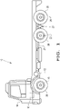
Figure 1 illustrates a side view of one embodiment of a work vehicle, the work vehicle comprising a rear tandem axle assembly according to an embodiment of the present invention; -
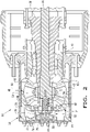
Figure 2 illustrates a cross-section view of a wheel hub with a housing and a reduction system, in which the reduction system is in the 2:1 speed ratio reduction operating position, according to an embodiment of the present invention; and -
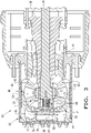
Figure 3 illustrates a cross-section view of a wheel hub inFigure 2 , in which the reduction system is in the operating position to disengage or freely rotate the wheels. - The terms "front", "rear", "left" and "right" used in connection with a vehicle and/or components thereof are generally determined with reference to the forward direction of travel of a vehicle and are not to be construed as limiting. The terms "longitudinal" and "transverse" are determined with reference to the forward and rearward direction of the vehicle and are not to be construed as limiting.
- Referring now to the figures, and more particularly to
Figure 1 , awork vehicle 10 is shown which typically includes achassis 12, acab 14 for an operator, amain engine 16, for example, adiesel engine 16, afront axle 18, arear axle assembly 20 with at least twoaxles wheels 26 attached to theaxles main drive axle 28 for transmitting driving force, i.e., drive torque, from theengine 16 to therear axle assembly 20 to provide primary traction for thework vehicle 10. Thefront wheels 26 of thefront axle 18 are normally configured to be steered to provide directional control for thework vehicle 10. Theengine 16, via the transmission system, may drive thewheels 26 of anyaxle work vehicle 10 may have any desired drive configuration, such as a 4x2, 6x6, 6x4, 6x2, 8x8, 8x4, or 10x6 drive configuration. Thework vehicle 10 may be in the form of any desiredvehicle 10, such as a heavy/large truck or bus. For example, thework vehicle 10 may be a commercial truck, up to 45 tons, with a 4x2 or 6x2 drive configuration. - Referring now to
Figures 2 and3 collectively, awheel hub 30 for thework vehicle 10 is shown. Thewheel hub 30 may generally include ahousing 32 and areduction system 34 arranged within thehousing 32. Thereduction system 34 has a first reduction operating position to provide a reduction in speed ratio, such as a 2:1 reduction, between a drivenaxle 36, for example, thedrive axle 36 extending from a rear differential of therespective axle 22, and the wheels 26 (Figure 2 ). Thereduction system 34 also has a second position of wheel disengagement or wheel release to cease transmitting the driving force from thedrive axle 36 to thewheels 26 so that thewheels 26 are completely free of traction (Figure 3 ). Accordingly, thereduction system 34 may selectively choose the appropriate speed ratio or disengagement position to appropriately accommodate an operating condition of thework vehicle 10, for example, fully loaded, partially loaded or unloaded. For example, when thework vehicle 10 is fully loaded, thereduction system 34 may provide the speed ratio reduction 2:1 in its reduction position to increase torque and force to thewheels 26 or alternatively, when thework vehicle 10 is unloaded, thereduction system 34 may disengage traction to thewheels 26 to significantly increase the fuel economy of thework vehicle 10. As can be appreciated, one or more of the front and/orrear axles wheel hubs 30. - The
housing 32 of thewheel hub 30 is connected to the liner orhousing 38 of thedrive axle 36 by means ofbearings 40. Thehousing 32 includes acylindrical portion 42 and aside end cap 44 connected to thecylindrical portion 42. The inner surface of theside end cap 44 may include teeth 46. It should be appreciated that thehousing 32 may have any desired shape and may comprise any desired material. - The
reduction system 34 may generally include aplanetary gear housing 48, asliding sleeve 50, and anactuation device 52 for sliding thesleeve 50 between the reduction and wheel release positions. Thereduction system 34 may also include a tiltingmember 54 for tilting thesleeve 50 so that it is engaged with theplanetary gearbox 48. - The
planetary gearbox 48 is operably connected between theaxle 36 and thewheels 26. Theplanetary gearbox 48 may be located within thehousing 32 Theplanetary gearbox 48 may generally include afixed gear 56, a movinggear 58, at least twointermediate gears gears planetary carrier 64 for carrying thegears fixed gear 56 may be securely attached to thehousing 38 of thedrive axle 36. The outermovable gear 58, e.g.,central gear 58, may be movably mounted within thehousing 32 of thewheel hub 30 via the bearing and/or a designated planetary liner. The intermediate gears 60, 62 are in the form of satellite orplanetary gears central gears planetary gearbox 48 includes fourplanetary gears gears gears planetary carriers 64 have a receiving orifice that at least partially receives thesleeve 50. Theplanetary carrier 64 may be in the form of any desired key, fork or gear carrier. As used herein, the termplanetary gearbox 48 broadly refers to the central planetary device which transmits force from thedrive axle 36 to thewheels 26. It should be appreciated that theplanetary gearbox 48 can be configured in various ways so as to have any desired number and size of gears. - The
sleeve 50 is selectively connectable to theplanetary gearbox 48 in order to provide the 2:1 speed reduction ratio andwheel release 26. Thesleeve 50 has aninner bore 66 connected to thedrive axle 36 and an outer side end 68 connected to theactuation device 52. Thebore 66 turns and opens towards the end of thedrive axle 36. It should be appreciated that thebore 66 may have an internal groove or teeth to engage with the corresponding engagement members on theaxle 36. Thesleeve 50 also has at least one group ofteeth 70 which are circumferentially arranged around the outer perimeter of thesleeve 50. Theteeth 70 of thesleeve 50 selectively engage with the corresponding teeth on thecentral gear 58 of theplanetary gearbox 48 in the reduction operating position (Figure 2 ). Thesleeve 50 does not operably engage with thehousing 32 in the wheel release operation position (Figure 3 ). As can be appreciated, thesleeve 50 may include one, two or more groups ofteeth 70 that engage respectively with theplanetary gearbox 48 and thehousing 32. Thesleeve 50 does not operably engage with thecarrier 64 by means of designated grooves or teeth in order to transmit driving force through the same; and thus, thesleeve 50 can rotate and slide independently in relation to thecarrier 64. Accordingly, when the driving force is transmitted through theplanetary gearbox 48 in the reduction position, the driving force passes from theaxle 36 through thesleeve 50, the outercentral gear 58 which is completely coupled to thesleeve 50, theplanetary gears gear 56, and finally out of thehousing 32 of thewheel hub 30 by means of thebearings 40. - The
actuation device 52 is operably connected to thesleeve 50. Theactuation device 52 includes afluid line 72, avalve 74, and apiston 76 which is fluidly connected to thefluid line 72. Thefluid line 72 extends through thehousing 32. Thefluid line 72 may be in the form of a designated hose pipe or a series of conduits, for example slots, within thewheel hub 30. Thevalve 74 may fluidly connect thefluid line 72 to thepiston 76. Thevalve 74 may be in the form of any desired valve. Thepiston 76 generally includes acylinder 78 that defines afluid chamber 80 and thepiston head 82 that is located within and slides relative to the cylinder 78 (Figure 3 ). Thecylinder 78 at least partially receives thesleeve 50 so that thefluid chamber 80 and thepiston head 82 are external relative to thesleeve 50. Thepiston head 82 is connected with the side end 68 of thesleeve 50 by means of (separated) bearings. Theactuation device 52 is illustrated as a pneumatic control device with apneumatic piston 76; however, theactuation device 52 can use any desired fluid. It should be appreciated that theactuation device 52 may also include an air pump, a compressor, various valves, seals, and/or an accumulator. Theactuation device 52 may also be operably connected to a control system within the cab of thework vehicle 10 so that the operator may enter a user command within the control system to consequently switch between the desired speed ratio. - The tilting
member 54 is located within thebore 66 of thesleeve 50, and is thereby connected between the end of thedrive axle 36 and thesleeve 50 to tilt thesleeve 50 so that it can engage with theplanetary gearbox 48 in the 2:1 reduction operating position. The tiltingmember 54 is internal relative to thesleeve 50 and acts in an opposite way to thepiston 76. The tiltingmember 54 may be in the form of any desired tiltingmember 54, such as acoil spring 54. - In operation, in the 2:1 reduction operating position, the
fluid chamber 80 is emptied of fluid so that the force of the tiltingmember 54 engages thesleeve 50 with the planetary gearbox 48 (Figure 2 ). In more detail, theteeth 70 of thesleeve 50 slide so as to engage with the movinggear 58. In the wheel release operating position, thefluid chamber 80 is filled with fluid so that the force of the fluid within thefluid chamber 80 overcomes the force of the tiltingmember 54 and disengages thesleeve 50 from the planetary gearbox 48 (Figure 3 ). Theteeth 70 of thesleeve 50 slide inwards to disengage the movinggear 58. In this way, thesleeve 50 is not connected to thecarrier 64, themobile gear 58 or thehousing 32 and thewheels 26 are consequently released from traction. - These and other advantages of the present invention will be apparent to those skilled in the art from the above descriptive report. Consequently, it should be recognised by those skilled in the art that changes or modifications may be made to the above described embodiments without departing from the broad inventive concepts of the invention. It is to be understood that the invention is not limited to the particular embodiments described herein, but is intended to include all changes and modifications falling within the scope and spirit of the invention.
Claims (15)
- WHEEL HUB (30) FOR MOUNTING A WHEEL (26) ON AN AXLE (36) OF A WORK VEHICLE (10) which comprises:a housing (32) comprising a side end cap (44); anda reduction system (34) comprising:a planetary gearbox (48) configured to be operably connected between the axle (36) and the wheel (26);a sleeve (50) configured to connect in a sliding manner to the axle (36); andan actuation device (52) connected to the sleeve (50) and configured to slide the sleeve (50),characterised in that:
the reduction system (34) comprises a first operating position in which the sleeve (50) engages with the planetary gearbox (48) to transmit the driving force from the axle (36) at a speed reduction rate, and a second operating position in which the sleeve (50) disengages from the planetary gearbox (48) in order to cease transmitting the driving force from the axle (36) to release the wheel (26). - WHEEL HUB (30), according to claim 1, characterised in that the wheel (26) is completely traction free in the second operating position of the reduction system (34).
- WHEEL HUB (30), according to claim 1 or claim 2, characterised in that the actuation device (52) comprises a fluid line (72) and a piston (76) fluidly connected to the fluid line (72).
- WHEEL HUB (30), according to claim 3, characterised in that the piston (76) comprises a cylinder (78) defining a fluid chamber (80) and a piston head (82) which is located within and slides relative to the cylinder (78), the cylinder (78) at least partially receives the sleeve (50), and the piston head (82) is connected to the sleeve (50) so that the piston (76) is configured to slide the sleeve (50) to engage with or disengage from the planetary gearbox (48).
- WHEEL HUB (30), according to claim 3 or claim 4, characterised in that the actuation device (52) comprises a single piston (76).
- WHEEL HUB (30), according to any of claims 3 to 5, characterised in that the piston (76) is a pneumatic piston (76).
- WHEEL HUB (30), according to claim 4, characterised in that the sleeve (50) comprises a side end (68) connected to the piston (76) and a bore (66) for connecting to the axle (36), and the sleeve (50) slides relative to the axle (36).
- WHEEL HUB (30), according to claim 7, characterised in that the reduction system (34) further comprises a tilting member (54) which is internally arranged within the bore (66) of the sleeve (50) and connected between the sleeve (50) and at the end of the axle (36), and the tilting member (54) is configured to tilt the sleeve (50) so that it is engaged with the planetary gearbox (48).
- WHEEL HUB (30), according to claim 8, characterised in that the tilting member (54) is a coil spring (54).
- WHEEL HUB (30), according to claim 8 or claim 9, characterised in that the fluid chamber (80) is external with respect to the sleeve (50), and the tilting member (54) is internal with respect to the sleeve (50) and acts on the sleeve (50) in an opposite manner with respect to the piston (76); in the first operating position the fluid chamber (80) is emptied of fluid so that the force of the tilting member (54) engages the sleeve (50) with the planetary gearbox (48); in the second operating position the fluid chamber (80) is filled with fluid so that the force of the fluid within the fluid chamber (80) overcomes the force of the tilting member (54) and disengages the sleeve (50) from the planetary gearbox (48).
- WHEEL HUB (30), according to any of the preceding claims, characterised in that the sleeve (50) is not operably connected to the housing (32) of the wheel hub (30) in the second operating position.
- WHEEL HUB (30), according to any of the preceding claims, characterised in that the sleeve (50) comprises at least one group of teeth (70), arranged circumferentially around the outer perimeter of the sleeve (50), for selectively engaging with the planetary gearbox (48) in the first operating position.
- WHEEL HUB (30), according to any one of the preceding claims, characterised in that the planetary gearbox (48) comprises a gear (56), a mobile gear (58), at least two planetary gears (60, 62), and a carrier (64) for carrying the planetary gears (60, 62), and the carrier (64) comprises a receiving orifice to at least partially receive the sleeve (50).
- WHEEL HUB (30), according to claim 13, characterised in that the sleeve (50) does not operably engage with the carrier (64) to transmit the driving force so that the sleeve (50) slides in relation to the carrier (64), and in the first operating position the sleeve (50) fully engages with the mobile gear (58) to transmit the driving force through the planetary gearbox (48)
- WHEEL HUB (30), according to any of the preceding claims, characterised in that the speed reduction ratio of the first operating position is 2:1.
Applications Claiming Priority (2)
| Application Number | Priority Date | Filing Date | Title |
|---|---|---|---|
| BR102019021704-9A BR102019021704B1 (en) | 2019-10-16 | WHEEL HUB FOR MOUNTING A WHEEL TO AN AXLE OF A WORKING VEHICLE | |
| PCT/BR2020/050404 WO2021072517A1 (en) | 2019-10-16 | 2020-10-13 | Wheel hub for mounting a wheel on an axle of a work vehicle |
Publications (3)
| Publication Number | Publication Date |
|---|---|
| EP4046818A1 true EP4046818A1 (en) | 2022-08-24 |
| EP4046818A4 EP4046818A4 (en) | 2023-11-22 |
| EP4046818B1 EP4046818B1 (en) | 2025-10-01 |
Family
ID=75537675
Family Applications (1)
| Application Number | Title | Priority Date | Filing Date |
|---|---|---|---|
| EP20877764.9A Active EP4046818B1 (en) | 2019-10-16 | 2020-10-13 | Wheel hub for mounting a wheel on an axle of a work vehicle |
Country Status (3)
| Country | Link |
|---|---|
| EP (1) | EP4046818B1 (en) |
| CN (1) | CN114728545B (en) |
| WO (1) | WO2021072517A1 (en) |
Family Cites Families (16)
| Publication number | Priority date | Publication date | Assignee | Title |
|---|---|---|---|---|
| US4040312A (en) * | 1974-10-29 | 1977-08-09 | Eaton Corporation | Planetary reduction drive unit |
| CN2507693Y (en) * | 2001-08-31 | 2002-08-28 | 泰安特种车制造厂 | Hub reduction gear |
| BRPI0400810A (en) * | 2004-02-11 | 2005-09-27 | Jose Francivaldo Pereira Lemos | Reduction for the differential hubs of extra heavy duty trucks |
| US20070117672A1 (en) * | 2005-11-18 | 2007-05-24 | Elvins Francis J | Tandem axle system |
| ITTO20060894A1 (en) * | 2006-12-15 | 2008-06-16 | Oto Melara Spa | MOTORIZED WHEEL FOR A MILITARY VEHICLE |
| US9109635B2 (en) * | 2013-02-07 | 2015-08-18 | Arvinmeritor Technology, Llc | Axle assembly having a moveable clutch collar |
| JP2016124441A (en) * | 2015-01-06 | 2016-07-11 | Ntn株式会社 | In-wheel motor drive unit |
| AU2016205869B2 (en) * | 2015-01-08 | 2019-08-22 | Iveco S.P.A. | Reduction system applied to a wheel hub, and more particularly to a wheel hub connected to a differential of a goods vehicle |
| TW201713516A (en) * | 2015-10-07 | 2017-04-16 | Chosen Co Ltd | Hub ratchet structure greatly enhancing the smoothness and agility of a hub ratchet in meshing interlocking movement, and increasing the transfer efficiency of the hub ratchet |
| TW201736158A (en) * | 2016-04-12 | 2017-10-16 | Shui-Sheng Bao | Flywheel set switchable to idle state for performing speed change on bicycle in situ capable of enabling the bicycle chain in forward rotation to enter the idle state |
| FR3055379B1 (en) * | 2016-08-24 | 2018-08-10 | Safran Landing Systems | AIRCRAFT WHEEL WITH SEPARABLE BEARING HOUSING |
| CN206206511U (en) * | 2016-11-28 | 2017-05-31 | 清远浩和仪器设计有限公司 | Wheel-side reduction device |
| BR102016029398B1 (en) * | 2016-12-14 | 2021-03-16 | Cnh Industrial America Llc | wheel hub for combined axles and vehicle |
| EP3554877B1 (en) * | 2016-12-14 | 2021-02-24 | Iveco S.p.A. | Freewheeling system for tandem axles |
| TW201834879A (en) * | 2017-03-21 | 2018-10-01 | 雅瑟斯工業股份有限公司 | Hub for bicycle wheel including a mandrel, a hub body, a toothed disc base and a ratchet device |
| CN110454550B (en) * | 2018-05-08 | 2022-02-01 | 德纳(无锡)技术有限公司 | Multistage planetary reduction transmission and mounting structure for vehicle |
-
2020
- 2020-10-13 EP EP20877764.9A patent/EP4046818B1/en active Active
- 2020-10-13 CN CN202080078533.5A patent/CN114728545B/en active Active
- 2020-10-13 WO PCT/BR2020/050404 patent/WO2021072517A1/en not_active Ceased
Also Published As
| Publication number | Publication date |
|---|---|
| EP4046818A4 (en) | 2023-11-22 |
| CN114728545A (en) | 2022-07-08 |
| WO2021072517A1 (en) | 2021-04-22 |
| BR102019021704A2 (en) | 2021-04-20 |
| EP4046818B1 (en) | 2025-10-01 |
| CN114728545B (en) | 2025-09-30 |
Similar Documents
| Publication | Publication Date | Title |
|---|---|---|
| US7028801B2 (en) | Multi-wheel-drive vehicle with a front transaxle device | |
| EP4047242B1 (en) | Wheel hub for mounting a wheel on an axle of a work vehicle | |
| CN201437330U (en) | Automobile chassis | |
| US20060000207A1 (en) | Regenerative drive system for trailers | |
| AU2016205869B2 (en) | Reduction system applied to a wheel hub, and more particularly to a wheel hub connected to a differential of a goods vehicle | |
| CN105236308A (en) | bidirectional forklift | |
| US9097340B2 (en) | Work vehicle | |
| EP4046818B1 (en) | Wheel hub for mounting a wheel on an axle of a work vehicle | |
| US8925702B2 (en) | PTM multiplex hydraulic diagram with two position spool valve | |
| SE540826C2 (en) | An axle gear system, a driving axle system and a motor vehicle | |
| CN113853321B (en) | Disengagement system for vehicles with first and second axles | |
| BR102019021704B1 (en) | WHEEL HUB FOR MOUNTING A WHEEL TO AN AXLE OF A WORKING VEHICLE | |
| US10245946B2 (en) | Platform heavy duty transfer case | |
| BR102019021705B1 (en) | WHEEL HUB FOR MOUNTING A WHEEL TO AN AXLE OF A WORKING VEHICLE | |
| EP3967536B1 (en) | Drive shaft for a vehicle with a first axle and a second axle that is a lifting axle | |
| RU2486071C1 (en) | Truck with front and rear drive axles | |
| RU2808306C2 (en) | Drive shaft for vehicle with first axle and second axle which can be lifted | |
| RU2493023C1 (en) | All-wheel drive truck | |
| US20160252173A1 (en) | Output transfer group for mobile machine powertrain | |
| RU2483945C1 (en) | All-wheel drive truck | |
| US9765881B2 (en) | Hydraulic circuit for powertrain having OTG | |
| BR102019007822B1 (en) | DISCONNECTION SYSTEM FOR A VEHICLE WITH A FIRST AXLE AND A SECOND AXLE | |
| RU2486069C1 (en) | All-wheel drive vehicle transmission |
Legal Events
| Date | Code | Title | Description |
|---|---|---|---|
| STAA | Information on the status of an ep patent application or granted ep patent |
Free format text: STATUS: THE INTERNATIONAL PUBLICATION HAS BEEN MADE |
|
| PUAI | Public reference made under article 153(3) epc to a published international application that has entered the european phase |
Free format text: ORIGINAL CODE: 0009012 |
|
| STAA | Information on the status of an ep patent application or granted ep patent |
Free format text: STATUS: REQUEST FOR EXAMINATION WAS MADE |
|
| 17P | Request for examination filed |
Effective date: 20220502 |
|
| AK | Designated contracting states |
Kind code of ref document: A1 Designated state(s): AL AT BE BG CH CY CZ DE DK EE ES FI FR GB GR HR HU IE IS IT LI LT LU LV MC MK MT NL NO PL PT RO RS SE SI SK SM TR |
|
| RIN1 | Information on inventor provided before grant (corrected) |
Inventor name: PEREIRA DE LEMOS, JOSE FRANCIVALDO |
|
| DAV | Request for validation of the european patent (deleted) | ||
| DAX | Request for extension of the european patent (deleted) | ||
| A4 | Supplementary search report drawn up and despatched |
Effective date: 20231020 |
|
| RIC1 | Information provided on ipc code assigned before grant |
Ipc: F16D 25/061 20060101ALN20231016BHEP Ipc: B60K 17/04 20060101ALI20231016BHEP Ipc: F16H 63/30 20060101ALI20231016BHEP Ipc: F16H 3/50 20060101ALI20231016BHEP Ipc: B60B 27/04 20060101AFI20231016BHEP |
|
| GRAP | Despatch of communication of intention to grant a patent |
Free format text: ORIGINAL CODE: EPIDOSNIGR1 |
|
| STAA | Information on the status of an ep patent application or granted ep patent |
Free format text: STATUS: GRANT OF PATENT IS INTENDED |
|
| RIC1 | Information provided on ipc code assigned before grant |
Ipc: F16D 25/061 20060101ALN20250417BHEP Ipc: B60K 17/04 20060101ALI20250417BHEP Ipc: F16H 63/30 20060101ALI20250417BHEP Ipc: F16H 3/50 20060101ALI20250417BHEP Ipc: B60B 27/04 20060101AFI20250417BHEP |
|
| INTG | Intention to grant announced |
Effective date: 20250508 |
|
| GRAS | Grant fee paid |
Free format text: ORIGINAL CODE: EPIDOSNIGR3 |
|
| GRAA | (expected) grant |
Free format text: ORIGINAL CODE: 0009210 |
|
| STAA | Information on the status of an ep patent application or granted ep patent |
Free format text: STATUS: THE PATENT HAS BEEN GRANTED |
|
| AK | Designated contracting states |
Kind code of ref document: B1 Designated state(s): AL AT BE BG CH CY CZ DE DK EE ES FI FR GB GR HR HU IE IS IT LI LT LU LV MC MK MT NL NO PL PT RO RS SE SI SK SM TR |
|
| REG | Reference to a national code |
Ref country code: GB Ref legal event code: FG4D Ref country code: CH Ref legal event code: F10 Free format text: ST27 STATUS EVENT CODE: U-0-0-F10-F00 (AS PROVIDED BY THE NATIONAL OFFICE) Effective date: 20251001 |
|
| REG | Reference to a national code |
Ref country code: IE Ref legal event code: FG4D |
|
| REG | Reference to a national code |
Ref country code: DE Ref legal event code: R096 Ref document number: 602020059903 Country of ref document: DE |
|
| PGFP | Annual fee paid to national office [announced via postgrant information from national office to epo] |
Ref country code: DE Payment date: 20251028 Year of fee payment: 6 |
|
| PGFP | Annual fee paid to national office [announced via postgrant information from national office to epo] |
Ref country code: IT Payment date: 20251031 Year of fee payment: 6 |
|
| PGFP | Annual fee paid to national office [announced via postgrant information from national office to epo] |
Ref country code: FR Payment date: 20251027 Year of fee payment: 6 |
|
| REG | Reference to a national code |
Ref country code: NL Ref legal event code: MP Effective date: 20251001 |
|
| REG | Reference to a national code |
Ref country code: AT Ref legal event code: MK05 Ref document number: 1842169 Country of ref document: AT Kind code of ref document: T Effective date: 20251001 |
|
| PG25 | Lapsed in a contracting state [announced via postgrant information from national office to epo] |
Ref country code: NL Free format text: LAPSE BECAUSE OF FAILURE TO SUBMIT A TRANSLATION OF THE DESCRIPTION OR TO PAY THE FEE WITHIN THE PRESCRIBED TIME-LIMIT Effective date: 20251001 |
|
| PG25 | Lapsed in a contracting state [announced via postgrant information from national office to epo] |
Ref country code: ES Free format text: LAPSE BECAUSE OF FAILURE TO SUBMIT A TRANSLATION OF THE DESCRIPTION OR TO PAY THE FEE WITHIN THE PRESCRIBED TIME-LIMIT Effective date: 20251001 |
|
| REG | Reference to a national code |
Ref country code: LT Ref legal event code: MG9D |
|
| PG25 | Lapsed in a contracting state [announced via postgrant information from national office to epo] |
Ref country code: NO Free format text: LAPSE BECAUSE OF FAILURE TO SUBMIT A TRANSLATION OF THE DESCRIPTION OR TO PAY THE FEE WITHIN THE PRESCRIBED TIME-LIMIT Effective date: 20260101 |
|
| PG25 | Lapsed in a contracting state [announced via postgrant information from national office to epo] |
Ref country code: AT Free format text: LAPSE BECAUSE OF FAILURE TO SUBMIT A TRANSLATION OF THE DESCRIPTION OR TO PAY THE FEE WITHIN THE PRESCRIBED TIME-LIMIT Effective date: 20251001 Ref country code: FI Free format text: LAPSE BECAUSE OF FAILURE TO SUBMIT A TRANSLATION OF THE DESCRIPTION OR TO PAY THE FEE WITHIN THE PRESCRIBED TIME-LIMIT Effective date: 20251001 Ref country code: HR Free format text: LAPSE BECAUSE OF FAILURE TO SUBMIT A TRANSLATION OF THE DESCRIPTION OR TO PAY THE FEE WITHIN THE PRESCRIBED TIME-LIMIT Effective date: 20251001 |
|
| PG25 | Lapsed in a contracting state [announced via postgrant information from national office to epo] |
Ref country code: RS Free format text: LAPSE BECAUSE OF FAILURE TO SUBMIT A TRANSLATION OF THE DESCRIPTION OR TO PAY THE FEE WITHIN THE PRESCRIBED TIME-LIMIT Effective date: 20260101 |
|
| PG25 | Lapsed in a contracting state [announced via postgrant information from national office to epo] |
Ref country code: IS Free format text: LAPSE BECAUSE OF FAILURE TO SUBMIT A TRANSLATION OF THE DESCRIPTION OR TO PAY THE FEE WITHIN THE PRESCRIBED TIME-LIMIT Effective date: 20260201 |
|
| PG25 | Lapsed in a contracting state [announced via postgrant information from national office to epo] |
Ref country code: CZ Free format text: LAPSE BECAUSE OF FAILURE TO SUBMIT A TRANSLATION OF THE DESCRIPTION OR TO PAY THE FEE WITHIN THE PRESCRIBED TIME-LIMIT Effective date: 20251001 Ref country code: PT Free format text: LAPSE BECAUSE OF FAILURE TO SUBMIT A TRANSLATION OF THE DESCRIPTION OR TO PAY THE FEE WITHIN THE PRESCRIBED TIME-LIMIT Effective date: 20260202 |
|
| PG25 | Lapsed in a contracting state [announced via postgrant information from national office to epo] |
Ref country code: PL Free format text: LAPSE BECAUSE OF FAILURE TO SUBMIT A TRANSLATION OF THE DESCRIPTION OR TO PAY THE FEE WITHIN THE PRESCRIBED TIME-LIMIT Effective date: 20251001 |
|
| PG25 | Lapsed in a contracting state [announced via postgrant information from national office to epo] |
Ref country code: LV Free format text: LAPSE BECAUSE OF FAILURE TO SUBMIT A TRANSLATION OF THE DESCRIPTION OR TO PAY THE FEE WITHIN THE PRESCRIBED TIME-LIMIT Effective date: 20251001 |