EP4046817A1 - Method for laser treatment of a timepiece component intended to darken at least one portion - Google Patents
Method for laser treatment of a timepiece component intended to darken at least one portion Download PDFInfo
- Publication number
- EP4046817A1 EP4046817A1 EP21158752.2A EP21158752A EP4046817A1 EP 4046817 A1 EP4046817 A1 EP 4046817A1 EP 21158752 A EP21158752 A EP 21158752A EP 4046817 A1 EP4046817 A1 EP 4046817A1
- Authority
- EP
- European Patent Office
- Prior art keywords
- predefined parameters
- laser
- treated
- laser beam
- pulses
- Prior art date
- Legal status (The legal status is an assumption and is not a legal conclusion. Google has not performed a legal analysis and makes no representation as to the accuracy of the status listed.)
- Granted
Links
- 238000000034 method Methods 0.000 title claims abstract description 39
- 238000013532 laser treatment Methods 0.000 title claims abstract description 21
- 239000000758 substrate Substances 0.000 claims abstract description 47
- 239000002086 nanomaterial Substances 0.000 claims abstract description 16
- 229910052751 metal Inorganic materials 0.000 claims description 22
- 239000002184 metal Substances 0.000 claims description 22
- 238000011282 treatment Methods 0.000 claims description 12
- 230000002093 peripheral effect Effects 0.000 claims description 11
- 238000005530 etching Methods 0.000 claims description 9
- 239000000463 material Substances 0.000 claims description 6
- BASFCYQUMIYNBI-UHFFFAOYSA-N platinum Chemical compound [Pt] BASFCYQUMIYNBI-UHFFFAOYSA-N 0.000 claims description 6
- 229910001369 Brass Inorganic materials 0.000 claims description 3
- RYGMFSIKBFXOCR-UHFFFAOYSA-N Copper Chemical compound [Cu] RYGMFSIKBFXOCR-UHFFFAOYSA-N 0.000 claims description 3
- BQCADISMDOOEFD-UHFFFAOYSA-N Silver Chemical compound [Ag] BQCADISMDOOEFD-UHFFFAOYSA-N 0.000 claims description 3
- 229910000831 Steel Inorganic materials 0.000 claims description 3
- RTAQQCXQSZGOHL-UHFFFAOYSA-N Titanium Chemical compound [Ti] RTAQQCXQSZGOHL-UHFFFAOYSA-N 0.000 claims description 3
- 239000010951 brass Substances 0.000 claims description 3
- 229910052802 copper Inorganic materials 0.000 claims description 3
- 239000010949 copper Substances 0.000 claims description 3
- PCHJSUWPFVWCPO-UHFFFAOYSA-N gold Chemical compound [Au] PCHJSUWPFVWCPO-UHFFFAOYSA-N 0.000 claims description 3
- 229910052737 gold Inorganic materials 0.000 claims description 3
- 239000010931 gold Substances 0.000 claims description 3
- 229910052697 platinum Inorganic materials 0.000 claims description 3
- 229910052709 silver Inorganic materials 0.000 claims description 3
- 239000004332 silver Substances 0.000 claims description 3
- 229910001220 stainless steel Inorganic materials 0.000 claims description 3
- 239000010959 steel Substances 0.000 claims description 3
- 239000010936 titanium Substances 0.000 claims description 3
- 229910052719 titanium Inorganic materials 0.000 claims description 3
- WFKWXMTUELFFGS-UHFFFAOYSA-N tungsten Chemical compound [W] WFKWXMTUELFFGS-UHFFFAOYSA-N 0.000 claims description 3
- 229910052721 tungsten Inorganic materials 0.000 claims description 3
- 239000010937 tungsten Substances 0.000 claims description 3
- 230000003287 optical effect Effects 0.000 description 6
- 238000006073 displacement reaction Methods 0.000 description 5
- 239000013598 vector Substances 0.000 description 4
- 238000004040 coloring Methods 0.000 description 3
- 238000003754 machining Methods 0.000 description 3
- 238000010586 diagram Methods 0.000 description 2
- 238000009826 distribution Methods 0.000 description 2
- 238000004519 manufacturing process Methods 0.000 description 2
- 230000000007 visual effect Effects 0.000 description 2
- VYZAMTAEIAYCRO-UHFFFAOYSA-N Chromium Chemical compound [Cr] VYZAMTAEIAYCRO-UHFFFAOYSA-N 0.000 description 1
- 238000003486 chemical etching Methods 0.000 description 1
- 229910052804 chromium Inorganic materials 0.000 description 1
- 239000011651 chromium Substances 0.000 description 1
- 230000000694 effects Effects 0.000 description 1
- 230000007613 environmental effect Effects 0.000 description 1
- 239000011521 glass Substances 0.000 description 1
- 238000010147 laser engraving Methods 0.000 description 1
- 239000000203 mixture Substances 0.000 description 1
- 238000005086 pumping Methods 0.000 description 1
- 239000000126 substance Substances 0.000 description 1
- 238000009827 uniform distribution Methods 0.000 description 1
Images
Classifications
-
- G—PHYSICS
- G04—HOROLOGY
- G04B—MECHANICALLY-DRIVEN CLOCKS OR WATCHES; MECHANICAL PARTS OF CLOCKS OR WATCHES IN GENERAL; TIME PIECES USING THE POSITION OF THE SUN, MOON OR STARS
- G04B37/00—Cases
- G04B37/22—Materials or processes of manufacturing pocket watch or wrist watch cases
-
- B—PERFORMING OPERATIONS; TRANSPORTING
- B23—MACHINE TOOLS; METAL-WORKING NOT OTHERWISE PROVIDED FOR
- B23K—SOLDERING OR UNSOLDERING; WELDING; CLADDING OR PLATING BY SOLDERING OR WELDING; CUTTING BY APPLYING HEAT LOCALLY, e.g. FLAME CUTTING; WORKING BY LASER BEAM
- B23K26/00—Working by laser beam, e.g. welding, cutting or boring
- B23K26/0006—Working by laser beam, e.g. welding, cutting or boring taking account of the properties of the material involved
-
- B—PERFORMING OPERATIONS; TRANSPORTING
- B23—MACHINE TOOLS; METAL-WORKING NOT OTHERWISE PROVIDED FOR
- B23K—SOLDERING OR UNSOLDERING; WELDING; CLADDING OR PLATING BY SOLDERING OR WELDING; CUTTING BY APPLYING HEAT LOCALLY, e.g. FLAME CUTTING; WORKING BY LASER BEAM
- B23K26/00—Working by laser beam, e.g. welding, cutting or boring
- B23K26/02—Positioning or observing the workpiece, e.g. with respect to the point of impact; Aligning, aiming or focusing the laser beam
- B23K26/06—Shaping the laser beam, e.g. by masks or multi-focusing
- B23K26/062—Shaping the laser beam, e.g. by masks or multi-focusing by direct control of the laser beam
- B23K26/0622—Shaping the laser beam, e.g. by masks or multi-focusing by direct control of the laser beam by shaping pulses
- B23K26/0624—Shaping the laser beam, e.g. by masks or multi-focusing by direct control of the laser beam by shaping pulses using ultrashort pulses, i.e. pulses of 1ns or less
-
- B—PERFORMING OPERATIONS; TRANSPORTING
- B23—MACHINE TOOLS; METAL-WORKING NOT OTHERWISE PROVIDED FOR
- B23K—SOLDERING OR UNSOLDERING; WELDING; CLADDING OR PLATING BY SOLDERING OR WELDING; CUTTING BY APPLYING HEAT LOCALLY, e.g. FLAME CUTTING; WORKING BY LASER BEAM
- B23K26/00—Working by laser beam, e.g. welding, cutting or boring
- B23K26/08—Devices involving relative movement between laser beam and workpiece
- B23K26/082—Scanning systems, i.e. devices involving movement of the laser beam relative to the laser head
-
- B—PERFORMING OPERATIONS; TRANSPORTING
- B23—MACHINE TOOLS; METAL-WORKING NOT OTHERWISE PROVIDED FOR
- B23K—SOLDERING OR UNSOLDERING; WELDING; CLADDING OR PLATING BY SOLDERING OR WELDING; CUTTING BY APPLYING HEAT LOCALLY, e.g. FLAME CUTTING; WORKING BY LASER BEAM
- B23K26/00—Working by laser beam, e.g. welding, cutting or boring
- B23K26/352—Working by laser beam, e.g. welding, cutting or boring for surface treatment
- B23K26/355—Texturing
-
- B—PERFORMING OPERATIONS; TRANSPORTING
- B23—MACHINE TOOLS; METAL-WORKING NOT OTHERWISE PROVIDED FOR
- B23K—SOLDERING OR UNSOLDERING; WELDING; CLADDING OR PLATING BY SOLDERING OR WELDING; CUTTING BY APPLYING HEAT LOCALLY, e.g. FLAME CUTTING; WORKING BY LASER BEAM
- B23K26/00—Working by laser beam, e.g. welding, cutting or boring
- B23K26/352—Working by laser beam, e.g. welding, cutting or boring for surface treatment
- B23K26/3568—Modifying rugosity
- B23K26/3576—Diminishing rugosity, e.g. grinding; Polishing; Smoothing
-
- B—PERFORMING OPERATIONS; TRANSPORTING
- B23—MACHINE TOOLS; METAL-WORKING NOT OTHERWISE PROVIDED FOR
- B23K—SOLDERING OR UNSOLDERING; WELDING; CLADDING OR PLATING BY SOLDERING OR WELDING; CUTTING BY APPLYING HEAT LOCALLY, e.g. FLAME CUTTING; WORKING BY LASER BEAM
- B23K26/00—Working by laser beam, e.g. welding, cutting or boring
- B23K26/352—Working by laser beam, e.g. welding, cutting or boring for surface treatment
- B23K26/3568—Modifying rugosity
- B23K26/3584—Increasing rugosity, e.g. roughening
-
- B—PERFORMING OPERATIONS; TRANSPORTING
- B41—PRINTING; LINING MACHINES; TYPEWRITERS; STAMPS
- B41M—PRINTING, DUPLICATING, MARKING, OR COPYING PROCESSES; COLOUR PRINTING
- B41M5/00—Duplicating or marking methods; Sheet materials for use therein
- B41M5/24—Ablative recording, e.g. by burning marks; Spark recording
-
- B—PERFORMING OPERATIONS; TRANSPORTING
- B44—DECORATIVE ARTS
- B44C—PRODUCING DECORATIVE EFFECTS; MOSAICS; TARSIA WORK; PAPERHANGING
- B44C1/00—Processes, not specifically provided for elsewhere, for producing decorative surface effects
- B44C1/005—Processes, not specifically provided for elsewhere, for producing decorative surface effects by altering locally the surface material
-
- B—PERFORMING OPERATIONS; TRANSPORTING
- B44—DECORATIVE ARTS
- B44C—PRODUCING DECORATIVE EFFECTS; MOSAICS; TARSIA WORK; PAPERHANGING
- B44C1/00—Processes, not specifically provided for elsewhere, for producing decorative surface effects
- B44C1/22—Removing surface-material, e.g. by engraving, by etching
- B44C1/228—Removing surface-material, e.g. by engraving, by etching by laser radiation
-
- G—PHYSICS
- G04—HOROLOGY
- G04B—MECHANICALLY-DRIVEN CLOCKS OR WATCHES; MECHANICAL PARTS OF CLOCKS OR WATCHES IN GENERAL; TIME PIECES USING THE POSITION OF THE SUN, MOON OR STARS
- G04B19/00—Indicating the time by visual means
- G04B19/06—Dials
-
- G—PHYSICS
- G04—HOROLOGY
- G04D—APPARATUS OR TOOLS SPECIALLY DESIGNED FOR MAKING OR MAINTAINING CLOCKS OR WATCHES
- G04D3/00—Watchmakers' or watch-repairers' machines or tools for working materials
- G04D3/0069—Watchmakers' or watch-repairers' machines or tools for working materials for working with non-mechanical means, e.g. chemical, electrochemical, metallising, vapourising; with electron beams, laser beams
-
- B—PERFORMING OPERATIONS; TRANSPORTING
- B23—MACHINE TOOLS; METAL-WORKING NOT OTHERWISE PROVIDED FOR
- B23K—SOLDERING OR UNSOLDERING; WELDING; CLADDING OR PLATING BY SOLDERING OR WELDING; CUTTING BY APPLYING HEAT LOCALLY, e.g. FLAME CUTTING; WORKING BY LASER BEAM
- B23K2103/00—Materials to be soldered, welded or cut
- B23K2103/02—Iron or ferrous alloys
- B23K2103/04—Steel or steel alloys
- B23K2103/05—Stainless steel
-
- B—PERFORMING OPERATIONS; TRANSPORTING
- B23—MACHINE TOOLS; METAL-WORKING NOT OTHERWISE PROVIDED FOR
- B23K—SOLDERING OR UNSOLDERING; WELDING; CLADDING OR PLATING BY SOLDERING OR WELDING; CUTTING BY APPLYING HEAT LOCALLY, e.g. FLAME CUTTING; WORKING BY LASER BEAM
- B23K2103/00—Materials to be soldered, welded or cut
- B23K2103/08—Non-ferrous metals or alloys
- B23K2103/12—Copper or alloys thereof
-
- B—PERFORMING OPERATIONS; TRANSPORTING
- B23—MACHINE TOOLS; METAL-WORKING NOT OTHERWISE PROVIDED FOR
- B23K—SOLDERING OR UNSOLDERING; WELDING; CLADDING OR PLATING BY SOLDERING OR WELDING; CUTTING BY APPLYING HEAT LOCALLY, e.g. FLAME CUTTING; WORKING BY LASER BEAM
- B23K2103/00—Materials to be soldered, welded or cut
- B23K2103/08—Non-ferrous metals or alloys
- B23K2103/14—Titanium or alloys thereof
Landscapes
- Physics & Mathematics (AREA)
- Engineering & Computer Science (AREA)
- Optics & Photonics (AREA)
- Plasma & Fusion (AREA)
- Mechanical Engineering (AREA)
- General Physics & Mathematics (AREA)
- Manufacturing & Machinery (AREA)
- Health & Medical Sciences (AREA)
- General Health & Medical Sciences (AREA)
- Toxicology (AREA)
- Laser Beam Processing (AREA)
Abstract
L'invention concerne un procédé de traitement laser d'un substrat (2) au moyen d'une source laser (4, 8, 10) agencée pour noircir au moins une portion (A) du substrat (2) comportant les étapes consistant à:- mettre en œuvre une première opération de traitement laser, suivant un premier jeu de paramètres prédéfini, pour noircir la portion (A) à traiter en créant des microstructures et des nanostructures,- mettre en œuvre une deuxième opération de traitement laser, suivant un deuxième jeu de paramètres prédéfini, pour lisser la surface de la portion (A) à traiter,- mettre en œuvre une troisième opération de traitement laser, suivant un troisième jeu de paramètres prédéfini, pour noircir la portion (A) à traiter en recréant des microstructures et des nanostructures sur essentiellement toute sa surface.The invention relates to a method for laser treatment of a substrate (2) by means of a laser source (4, 8, 10) arranged to blacken at least a portion (A) of the substrate (2) comprising the steps consisting in :- implementing a first laser treatment operation, according to a first set of predefined parameters, to blacken the portion (A) to be treated by creating microstructures and nanostructures,- implementing a second laser treatment operation, according to a second set of predefined parameters, to smooth the surface of the portion (A) to be treated, - implementing a third laser treatment operation, according to a third set of predefined parameters, to blacken the portion (A) to be treated by recreating microstructures and nanostructures over essentially its entire surface.
Description
La présente invention concerne un procédé de traitement laser d'un substrat métallique pour composant horloger, au moyen d'une source laser destinée à émettre des impulsions de durées égales ou inférieures à la picoseconde et agencée pour définir un faisceau laser incident mobile relativement au substrat et réaliser un traitement de ce dernier pour en noircir au moins une portion de manière sélective.The present invention relates to a process for the laser treatment of a metal substrate for a watch component, by means of a laser source intended to emit pulses of duration equal to or less than one picosecond and arranged to define a moving incident laser beam relative to the substrate. and carrying out a treatment of the latter in order to blacken at least a portion thereof selectively.
De tels procédés de traitement laser de composants horlogers sont déjà connus de l'état de la technique, et sont avantageux notamment parce qu'ils permettent de se passer de l'utilisation du chrome, ce qui est très intéressant du point de vue environnemental.Such processes for the laser treatment of watch components are already known in the state of the art, and are advantageous in particular because they make it possible to dispense with the use of chromium, which is very interesting from an environmental point of view.
Ainsi, par exemple, la demande de brevet
Par ailleurs, la demande de brevet
Un but principal de la présente invention est de proposer un procédé alternatif aux procédés de traitement de composants horlogers par faisceau laser connus de l'art antérieur, le procédé selon l'invention permettant la réalisation d'une portion noire sur le composant horloger traité, avec une bonne profondeur du noir obtenu et une apparence très propre, notamment une surface uniforme de la portion traitée, et donc avec une qualité perçue élevée.A main object of the present invention is to propose an alternative method to the methods of treatment of watchmaking components by laser beam known from the prior art, the method according to the invention allowing the production of a black portion on the treated watchmaking component, with a good depth of black obtained and a very clean appearance, in particular a uniform surface of the treated portion, and therefore with a high perceived quality.
A cet effet, la présente invention concerne plus particulièrement un procédé de traitement laser d'un substrat métallique pour composant horloger du type mentionné plus haut, caractérisé par le fait qu'il comporte les étapes consistant à:
- se munir d'un substrat métallique comprenant une portion à traiter,
- mettre en œuvre une première opération de traitement laser visant à balayer la portion à traiter avec un faisceau laser incident, suivant un premier jeu de paramètres prédéfini, adapté pour noircir la portion à traiter en créant des microstructures et des nanostructures sur essentiellement toute sa surface,
- mettre en œuvre une deuxième opération de traitement laser visant à balayer la portion à traiter avec un faisceau laser incident, suivant un deuxième jeu de paramètres prédéfini, différent du premier jeu de paramètre prédéfini et adapté pour lisser la surface de la portion à traiter, par réduction de la rugosité de la surface de la portion à traiter d'au moins 40%, préférablement d'au moins 50%,
- mettre en œuvre une troisième opération de traitement laser visant à balayer la portion à traiter avec un faisceau laser incident, suivant un troisième jeu de paramètres prédéfini, similaire au premier jeu de paramètres prédéfini et adapté pour noircir la portion à traiter en recréant des microstructures et des nanostructures sur essentiellement toute sa surface.
- obtain a metal substrate comprising a portion to be treated,
- implement a first laser treatment operation aimed at scanning the portion to be treated with an incident laser beam, according to a first set of predefined parameters, suitable for blackening the portion to be treated by creating microstructures and nanostructures over essentially its entire surface,
- implement a second laser treatment operation aimed at scanning the portion to be treated with an incident laser beam, according to a second set of predefined parameters, different from the first set of predefined parameters and adapted to smooth the surface of the portion to be treated, by reduction of the roughness of the surface of the portion to be treated by at least 40%, preferably by at least 50%,
- implement a third laser processing operation aimed at scanning the portion to be processed with an incident laser beam, according to a third set of predefined parameters, similar to the first set of predefined parameters and adapted to darken the portion to be processed by recreating microstructures and nanostructures over essentially its entire surface.
Le substrat à traiter peut être un composant horloger en tant que tel ou seulement une portion d'un composant horloger, soit réalisé d'une pièce avec le reste du composant, soit rapportée sur le reste du composant avant ou après la mise en œuvre du procédé selon l'invention, sans sortir du cadre de cette dernière.The substrate to be treated can be a watch component as such or only a portion of a watch component, either made in one piece with the rest of the component, or attached to the rest of the component before or after the implementation of the method according to the invention, without departing from the scope of the latter.
Grâce à ces caractéristiques, il est possible de noircir une portion à traiter avec l'obtention d'un noir profond et parfaitement uniforme, grâce à la grande finesse et à la répartition uniforme des microstructures créées. Le procédé selon l'invention permet de réaliser un tel traitement avec un contrôle très précis, donc avec une bonne reproductibilité. En effet, la première opération de traitement laser, visant à noircir la portion à traiter, permet de créer un état de surface présentant une capacité d'absorption élevée de l'énergie du faisceau laser balayant la portion à traiter lors de la deuxième opération. Il est ainsi possible d'obtenir un nouvel état de surface, présentant une coloration sensiblement grise, parfaitement adapté pour absorber l'énergie apportée par le faisceau laser lors de la troisième opération de traitement, visant à noircir à nouveau la portion à traiter, avec un résultat qualitatif amélioré en comparaison avec le résultat obtenu après mise en œuvre de la première opération.Thanks to these characteristics, it is possible to blacken a portion to be treated obtaining a deep and perfectly uniform black, thanks to the great finesse and uniform distribution of the microstructures created. The method according to the invention makes it possible to carry out such a treatment with very precise control, therefore with good reproducibility. Indeed, the first laser treatment operation, aimed at blackening the portion to be treated, makes it possible to create a surface condition having a high capacity for absorbing the energy of the laser beam scanning the portion to be treated during the second operation. It is thus possible to obtain a new surface state, having a substantially gray coloring, perfectly suited to absorb the energy provided by the laser beam during the third treatment operation, aimed at blackening again the portion to be treated, with an improved qualitative result compared to the result obtained after implementation of the first operation.
De manière avantageuse, on peut prévoir que le premier jeu de paramètres prédéfini inclue une valeur de fluence comprise entre 0.05 et 0.35 J/cm2.Advantageously, provision can be made for the first set of predefined parameters to include a fluence value of between 0.05 and 0.35 J/cm 2 .
De manière alternative ou complémentaire, on peut avantageusement prévoir que le premier jeu de paramètres prédéfini inclue une valeur de taux de recouvrement longitudinal supérieure ou égale à 65% et strictement inférieure à 100%, préférablement comprise entre 65% et 85%.Alternatively or additionally, provision can advantageously be made for the first set of predefined parameters to include a longitudinal overlap rate value greater than or equal to 65% and strictly less than 100%, preferably between 65% and 85%.
De manière alternative ou complémentaire, on peut avantageusement prévoir que le deuxième jeu de paramètres prédéfini inclue une valeur de fluence comprise entre 0.15 et 1 J/cm2.Alternatively or additionally, provision can advantageously be made for the second set of predefined parameters to include a fluence value of between 0.15 and 1 J/cm 2 .
De manière alternative ou complémentaire, on peut avantageusement prévoir que le deuxième jeu de paramètres prédéfini inclue une valeur de taux de recouvrement longitudinal supérieure ou égale à 85% et strictement inférieure à 100%, préférablement supérieure ou égale à 90% et inférieure à 99%.Alternatively or additionally, provision can advantageously be made for the second set of predefined parameters to include a longitudinal overlap rate value greater than or equal to 85% and strictly less than 100%, preferably greater than or equal to 90% and less than 99%.
De manière alternative ou complémentaire, on peut avantageusement prévoir que le troisième jeu de paramètres prédéfini inclue une valeur de fluence comprise entre 0.05 et 0.35 J/cm2.Alternatively or additionally, provision can advantageously be made for the third set of predefined parameters to include a fluence value of between 0.05 and 0.35 J/cm 2 .
De manière alternative ou complémentaire, on peut avantageusement prévoir que le troisième jeu de paramètres prédéfini inclue une valeur de taux de recouvrement longitudinal supérieure ou égale à 65% et strictement inférieure à 100%, préférablement comprise entre 65% et 85%.Alternatively or additionally, provision can advantageously be made for the third set of predefined parameters to include a longitudinal overlap rate value greater than or equal to 65% and strictly less than 100%, preferably between 65% and 85%.
Selon une variante de réalisation préférée, on peut prévoir qu'au cours de la première opération et/ou de la troisième opération, la source laser soit agencée pour émettre des impulsions laser en mode "burst", en étant réparties en des groupes d'impulsions successifs, avec une période de groupe P, les impulsions d'un groupe donné étant émises pendant 20 à 100% de la période P.According to a preferred variant embodiment, provision can be made for the laser source to be arranged during the first operation and/or the third operation to emit laser pulses in "burst" mode, being divided into groups of successive pulses, with a group period P, the pulses of a given group being emitted during 20 to 100% of the period P.
Selon un mode de réalisation préféré, lorsque la portion à traiter est située dans une gravure préalablement réalisée dans le substrat métallique et présente une paroi périphérique au moins partiellement incurvée pour relier la surface libre du substrat métallique au fond de la gravure, on peut avantageusement prévoir que le procédé comporte une étape supplémentaire consistant à mettre en œuvre une quatrième opération de traitement laser visant à balayer au moins une partie de la paroi périphérique avec un faisceau laser incident, suivant un quatrième jeu de paramètres prédéfini, différent des premier, deuxième et troisième jeux de paramètres prédéfinis et adapté pour noircir la paroi périphérique en créant des microstructures et des nanostructures sur essentiellement toute sa surface.According to a preferred embodiment, when the portion to be treated is located in an etching previously made in the metal substrate and has an at least partially curved peripheral wall to connect the free surface of the metal substrate to the bottom of the etching, it is advantageous to provide that the method comprises an additional step consisting in implementing a fourth laser processing operation aimed at scanning at least part of the peripheral wall with an incident laser beam, according to a fourth set of predefined parameters, different from the first, second and third sets of predefined parameters and adapted to blacken the peripheral wall by creating microstructures and nanostructures on essentially its entire surface.
Dans ce cas, on peut avantageusement prévoir que le quatrième jeu de paramètres prédéfini inclue une valeur de fluence comprise entre 0.10 et 0.25 J/cm2.In this case, provision can advantageously be made for the fourth set of predefined parameters to include a fluence value of between 0.10 and 0.25 J/cm 2 .
En outre, on peut avantageusement prévoir dans ce cas, de manière alternative ou complémentaire, que le quatrième jeu de paramètres prédéfini inclue une valeur de taux de recouvrement longitudinal supérieure ou égale à 85% et strictement inférieure à 100%, préférablement supérieure ou égale à 90% et inférieure à 99%.In addition, provision can advantageously be made in this case, alternatively or additionally, for the fourth set of predefined parameters to include a higher longitudinal overlap rate value or equal to 85% and strictly less than 100%, preferably greater than or equal to 90% and less than 99%.
Selon un mode de réalisation préféré, on peut prévoir que le substrat comporte un ou plusieurs des matériaux pris dans le groupe comprenant: les aciers, y compris les aciers inoxydables, le titane, le cuivre, le laiton, l'or, l'argent, le platine, le tungstène.According to a preferred embodiment, provision may be made for the substrate to comprise one or more of the materials taken from the group comprising: steels, including stainless steels, titanium, copper, brass, gold, silver , platinum, tungsten.
D'autres caractéristiques et avantages de la présente invention apparaîtront plus clairement à la lecture de la description détaillée d'un mode de réalisation préféré qui suit, faite en référence aux dessins annexés donnés à titre d'exemple non limitatif et dans lesquels:
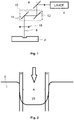
- la
figure 1 représente un schéma de principe simplifié d'une source laser permettant la mise en œuvre du procédé selon la présente invention, et - la
figure 2 représente une vue en coupe transversale schématique d'une portion à traiter située dans une gravure selon un mode de réalisation préféré de la présente invention.
- the
figure 1 represents a simplified block diagram of a laser source allowing the implementation of the method according to the present invention, and - the
figure 2 shows a schematic cross-sectional view of a portion to be treated located in an engraving according to a preferred embodiment of the present invention.
La
Plus précisément, le procédé d'usinage par faisceau laser selon la présente invention vise à traiter un substrat métallique 2 pour un composant horloger (non représenté dans son intégralité), ce substrat métallique 2 absorbant avantageusement au moins partiellement la lumière du faisceau laser à la longueur d'onde du faisceau laser utilisé pour réaliser le traitement, préférablement entre 500 et 1100 nm. Ainsi, de manière générale, on pourra mettre en œuvre le procédé selon l'invention en relation avec toutes sortes de matériaux susceptibles d'être usinés par laser, et le substrat pourra comporter un ou plusieurs des matériaux pris dans le groupe comprenant: les aciers, y compris les aciers inoxydables, le titane, le cuivre, le laiton, l'or, l'argent, le platine, le tungstène, à titre illustratif non limitatif.More specifically, the laser beam machining method according to the present invention aims to treat a
Le substrat métallique 2 peut être directement un composant horloger en tant que tel ou seulement une portion d'un composant horloger, soit réalisée d'une pièce avec le reste du composant, soit rapportée sur le reste du composant, sans sortir du cadre de l'invention.The
Par ailleurs, on pourra prévoir que le composant horloger soit directement visible sur la pièce d'horlogerie correspondante, en étant situé à l'extérieur de la boite ou à l'intérieur mais en étant visible au travers d'une glace, ou il peut être logé à l'intérieur de la boite et n'être au moins partiellement visible qu'une fois celle-ci ouverte.Furthermore, provision may be made for the timepiece component to be directly visible on the corresponding timepiece, being located outside the case or inside but being visible through a glass, or it may be housed inside the box and only be at least partially visible once it has been opened.
De manière générale, pour réaliser l'usinage selon l'invention, on utilise une première source laser 4 agencée, en relation avec un dispositif optique, pour définir un faisceau laser incident 6 destiné à réaliser le traitement souhaité sur le substrat métallique 2 du composant horloger, c'est-à-dire un traitement visant à en noircir au moins une portion prédéfinie.In general, to carry out the machining according to the invention, a
Plus précisément, le dispositif optique peut comporter, à titre illustratif non limitatif, au moins un premier miroir 8 agencé en sortie de la première source laser 4, cette dernière pouvant typiquement être associée à une tête galvanométrique 10 comprenant un jeu de miroirs supplémentaires, ici schématisés sous la forme de deux miroirs 12 et 14, permettant de contrôler la direction de propagation du faisceau laser incident 6 et de faire faire un balayage à ce dernier pour réaliser le traitement requis sur le substrat métallique 2, selon l'invention. Le dispositif optique comporte également, de manière avantageuse, un dispositif de focalisation 16, schématisé ici sous la forme d'une lentille convergente pour définir un plan de focalisation souhaité pour le faisceau laser incident 6. En alternative ou en complément, il est possible de prévoir un support mobile pour le substrat métallique 2, pour pouvoir le déplacer relativement au faisceau laser incident, sans sortir du cadre de la présente invention.More specifically, the optical device may comprise, by way of non-limiting illustration, at least one
De manière avantageuse, la première source laser 4 peut être associée au dispositif optique directement à l'intérieur d'une machine à commande numérique multi-axes.Advantageously, the
Lorsqu'une machine à commande numérique est utilisée, elle est avantageusement programmée pour contrôler le faisceau laser incident 6 et ses déplacements de façon appropriée pour procéder au traitement du substrat métallique 2 suivant un trajet prédéfini. La machine à commande numérique comporte typiquement un dispositif de pilotage, à cet effet, prenant en compte la géométrie du substrat métallique 2 et du traitement à réaliser, et définissant la vitesse de balayage de la surface à traiter par le faisceau laser incident 6 ainsi que l'amplitude de mouvement du faisceau et la génération des impulsions laser, de manière à obtenir le résultat souhaité.When a numerically controlled machine is used, it is advantageously programmed to control the
De manière avantageuse, la première source laser est choisie de telle manière qu'elle définisse un faisceau laser incident 6 composé d'impulsions lumineuses dont la durée est de l'ordre de grandeur de la picoseconde ou plus courte. De plus, le dispositif optique est préférablement agencé de telle manière que le faisceau laser incident 6 présente un plan focal situé sensiblement à la surface du substrat métallique 2.Advantageously, the first laser source is chosen in such a way that it defines an
Typiquement, pour traiter des substrats tels que ceux mentionnés plus haut, on pourra choisir une première source laser 4 telle que le faisceau laser incident 6 soit composé d'impulsions présentant une fréquence moyenne comprise entre 1 et 200 kHz, et telle que celui-ci présente une puissance moyenne comprise entre 1 et 10 Watts. En outre, on peut avantageusement prévoir que le faisceau laser incident présente une énergie d'impulsion comprise entre 2 et 10 µJ et que la vitesse du déplacement relatif entre le faisceau laser incident et le substrat soit comprise entre 10 et 300 mm/s. Ces différents paramètres peuvent avantageusement être affinés pour prendre en compte la composition exacte du substrat métallique.Typically, to treat substrates such as those mentioned above, it is possible to choose a
De manière préférée, le traitement laser selon la présente invention est réalisé par une programmation adéquate de la source laser (dans son acception large, c'est-à-dire en incluant le dispositif optique et/ou un support mobile permettant d'induire un déplacement relatif entre le faisceau incident et le substrat métallique), autrement dit en définissant au moins un vecteur, préférablement une pluralité de vecteurs, dont chacun est délimité par un point de départ et un point d'arrivée et composé d'un trajet à parcourir par le faisceau laser incident 6 relativement au substrat métallique 2, et d'une série d'impacts du faisceau laser incident 6 le long du trajet.Preferably, the laser treatment according to the present invention is carried out by suitable programming of the laser source (in its broad sense, that is to say by including the optical device and/or a mobile support making it possible to induce a relative displacement between the incident beam and the metallic substrate), in other words by defining at least one vector, preferably a plurality of vectors, each of which is delimited by a starting point and an ending point and composed of a path to be traveled by the
Le procédé selon la présente invention concerne indifféremment la mise en œuvre de simples passes ou de passes multiples, éventuellement croisées ("cross-hatch").The method according to the present invention concerns either the implementation of single passes or multiple passes, possibly crossed ("cross-hatch").
La
Selon ce mode de réalisation préféré illustratif et non limitatif, le substrat métallique 2 présente une portion gravée, la gravure 20 correspondante étant réalisée préalablement à la mise en œuvre du procédé de traitement selon l'invention. Le procédé de traitement laser selon la présente invention peut bien entendu être mis en œuvre directement sur la surface libre d'un substrat qui ne serait pas gravée au préalable, sans pour autant sortir du cadre de l'invention tel que défini par les revendications.According to this illustrative and non-limiting preferred embodiment, the
La gravure peut par exemple être réalisée par laser ou par attaque chimique. Lorsqu'elle est réalisée par un procédé de gravure laser conventionnel, la gravure présente typiquement des flancs droits reliés au fond de la gravure par des jonctions sensiblement à angle droit. Il est possible d'introduire un décalage temporel entre le début du déplacement du faisceau laser, au début de chaque vecteur de gravure, et le début de l'émission des impulsions laser, pour incurver la jonction entre le flanc initial et le fond de la gravure. De manière similaire, il est possible d'arrêter l'émission des impulsions laser avant que le faisceau laser n'ait atteint la fin d'un vecteur de gravure pour incurver la jonction entre le flanc final et le fond de la gravure, comme illustré sur la
Conformément à la présente invention, il est prévu que le procédé de traitement laser du substrat métallique 2 comporte les étapes consistant à:
- mettre en œuvre une première opération de traitement laser visant à balayer la portion à traiter, repérée par la lettre A sur la
figure 2 , avec un faisceau laser incident, suivant un premier jeu de paramètres prédéfini, adapté pour noircir la portion A à traiter en créant des microstructures et des nanostructures sur essentiellement toute sa surface, - mettre en œuvre une deuxième opération de traitement laser visant à balayer la portion A à traiter avec un faisceau laser incident, suivant un deuxième jeu de paramètres prédéfini, différent du premier jeu de paramètre prédéfini et adapté pour lisser la surface de la portion A à traiter, par réduction de la rugosité de la surface de la portion A à traiter d'au moins 40%, préférablement d'au moins 50%,
- mettre en œuvre une troisième opération de traitement laser visant à balayer la portion A à traiter avec un faisceau laser incident, suivant un troisième jeu de paramètres prédéfini, similaire au premier jeu de paramètres prédéfini et adapté pour noircir la portion A à traiter en recréant des microstructures et des nanostructures sur essentiellement toute sa surface.
- implement a first laser treatment operation aimed at scanning the portion to be treated, marked with the letter A on the
picture 2 - implement a second laser treatment operation aimed at scanning the portion A to be treated with an incident laser beam, according to a second set of predefined parameters, different from the first set of predefined parameters and adapted to smooth the surface of the portion A to be treated , by reducing the roughness of the surface of portion A to be treated by at least 40%, preferably by at least 50%,
- implement a third laser processing operation aimed at scanning the portion A to be processed with an incident laser beam, according to a third set of predefined parameters, similar to the first set of predefined parameters and adapted to darken the portion A to be processed by recreating microstructures and nanostructures over essentially its entire surface.
De manière préférée, le premier jeu de paramètres prédéfini inclut une valeur de fluence comprise entre 0.05 et 0.35 J/cm2.Preferably, the first set of predefined parameters includes a fluence value of between 0.05 and 0.35 J/cm 2 .
De manière alternative ou complémentaire, le premier jeu de paramètres prédéfini inclut préférablement une valeur de taux de recouvrement longitudinal supérieure ou égale à 65% et strictement inférieure à 100%, préférablement comprise entre 65% et 85%.Alternatively or additionally, the first set of predefined parameters preferably includes a longitudinal overlap rate value greater than or equal to 65% and strictly less than 100%, preferably between 65% and 85%.
Par ailleurs, le deuxième jeu de paramètres prédéfini inclut préférablement une valeur de fluence comprise entre 0.15 et 1 J/cm2, et une valeur de taux de recouvrement longitudinal supérieure ou égale à 85% et strictement inférieure à 100%, préférablement supérieure ou égale à 90% et inférieure à 99%.Furthermore, the second set of predefined parameters preferably includes a fluence value of between 0.15 and 1 J/cm 2 , and a longitudinal overlap rate value greater than or equal to 85% and strictly less than 100%, preferably greater than or equal to than 90% and less than 99%.
Par ailleurs, le troisième jeu de paramètres prédéfini inclut préférablement une valeur de fluence comprise entre 0.05 et 0.35 J/cm2, et une valeur de taux de recouvrement longitudinal supérieure ou égale à 65% et strictement inférieure à 100%, préférablement comprise entre 65% et 85%.Furthermore, the third set of predefined parameters preferably includes a fluence value comprised between 0.05 and 0.35 J/cm 2 , and a longitudinal overlap rate value greater than or equal to 65% and strictly less than 100%, preferably comprised between 65 % and 85%.
Lorsque la portion A à traiter est située dans une gravure et présente une paroi périphérique au moins partiellement incurvée pour relier la surface libre du substrat métallique 2 au fond de la gravure, comme illustré sur la
Selon un mode de réalisation préféré, le quatrième jeu de paramètres prédéfini inclut une valeur de fluence comprise entre 0.10 et 0.25 J/cm2.According to a preferred embodiment, the fourth set of predefined parameters includes a fluence value of between 0.10 and 0.25 J/cm 2 .
En outre, on peut avantageusement prévoir dans ce cas, de manière alternative ou complémentaire, que le quatrième jeu de paramètres prédéfini inclue une valeur de taux de recouvrement longitudinal supérieure ou égale à 85% et strictement inférieure à 100%, préférablement supérieure ou égale à 90% et inférieure à 99%.In addition, it can advantageously be provided in this case, alternatively or additionally, for the fourth set of predefined parameters to include a longitudinal overlap rate value greater than or equal to 85% and strictly less than 100%, preferably greater than or equal to 90% and less than 99%.
Grâce à cette opération supplémentaire, on obtient un aspect noir relativement uniforme de la portion traitée du substrat métallique 2, tant au niveau du fond de la gravure que de ses flancs, ce qui lui confère une apparence d'un niveau qualitatif très élevé.By virtue of this additional operation, a relatively uniform black appearance is obtained for the treated portion of the
De manière générale, la source laser est préférablement programmée de telle manière que le taux de recouvrement latéral soit compris entre 50 et 98% lors de la mise en œuvre des trois premières opérations de traitement du fond de la gravure (ou de la surface libre du substrat le cas échéant). Généralement, une seule passe devrait suffire pour traiter la paroi périphérique B de la gravure, mais un taux de recouvrement latéral similaire peut être mis en œuvre lorsque plusieurs passes sont nécessaires.In general, the laser source is preferably programmed in such a way that the lateral coverage rate is between 50 and 98% during the implementation of the first three processing operations of the bottom of the engraving (or of the free surface of the substrate if applicable). Typically, a single pass should be sufficient to process the peripheral wall B of the etch, but a similar side coverage rate can be implemented when multiple passes are required.
Selon une variante de réalisation préférée de mise en œuvre des première et troisième opérations visant à créer des microstructures et, surtout, des nanostructures, on utilise préférablement un mode "burst" de la source laser 4. De manière générale, une source laser émet typiquement des impulsions de faible énergie, avec une fréquence propre Fosc, filtrées pour sélectionner des impulsions à une fréquence Fpp qui est un quotient entier de la fréquence propre Fosc. Ces impulsions sont généralement amplifiées grâce à effet de pompage, par l'association d'une autre source laser permettant d'augmenter l'énergie des impulsions ainsi obtenues. Ces impulsions peuvent ensuite être fractionnées, en mode burst, en groupes d'impulsions d'énergie réduite, de fréquence Fpp, les impulsions au sein de chaque groupe présentant une fréquence Fosc. Ainsi, le mode burst permet d'éclater chaque impulsion d'énergie E, en groupes de N impulsions dont chacune présente une énergie E/N. Il est alors possible d'émettre des groupes d'impulsions d'énergie réduite avec une fréquence F qui est un quotient entier de la fréquence de groupes Fpp. Ainsi, au cours d'une période P=1/F, il est possible d'émettre au maximum R groupes d'impulsions d'énergie réduite, R étant égal à P/Ppp, avec Ppp=1/Fpp.According to a preferred implementation variant of the first and third operations aimed at creating microstructures and, above all, nanostructures, a "burst" mode of the
La Demanderesse a constaté, au cours de ses essais expérimentaux, qu'une répartition dans le temps de l'énergie transmise au substrat permet d'améliorer la qualité du traitement noir réalisé.The Applicant has observed, during its experimental tests, that a distribution over time of the energy transmitted to the substrate makes it possible to improve the quality of the black treatment carried out.
Par conséquent, l'utilisation du mode burst se révèle avantageuse pour répartir l'énergie d'une seule impulsion sous la forme d'un groupe d'impulsions d'énergie réduite (dont la somme correspond à l'énergie de l'impulsion unique).Therefore, the use of the burst mode proves advantageous to distribute the energy of a single pulse in the form of a group of pulses of reduced energy (the sum of which corresponds to the energy of the single pulse ).
Le mode burst peut être modelé plus finement en fonction des besoins, en définissant le nombre de groupes d'impulsions émises au cours de chaque période P, avec la limite supérieure égale à R comme exposé plus haut. Lorsque le nombre de groupes d'impulsions est inférieur à R, on comprend que chaque période P comporte un certain nombre de groupes d'impulsions puis un délai d'attente, sans impulsion, jusqu'à la fin de la période, avant le début de la période suivante. Ainsi, en comparaison avec l'utilisation d'impulsions de période P de forte énergie, un tel mode burst permet d'étaler l'apport de la même quantité d'énergie au substrat sur une fraction de la même période P, au lieu de le faire sur la durée d'une impulsion unique, tout en préservant éventuellement un délai de repos à la matière.The burst mode can be modeled more finely according to the needs, by defining the number of groups of pulses emitted during each period P, with the upper limit equal to R as explained above. When the number of groups of pulses is less than R, it is understood that each period P comprises a certain number of groups of pulses then a waiting period, without a pulse, until the end of the period, before the start of the following period. Thus, in comparison with the use of pulses of period P of high energy, such a burst mode makes it possible to spread the supply of the same quantity of energy to the substrate over a fraction of the same period P, instead of do so over the duration of a single pulse, while optionally preserving a rest delay to the material.
Finalement, la Demanderesse a constaté qu'une répartition des impulsions sur 20 à 100% de la durée de la période P permet d'obtenir un résultat de meilleure qualité, y compris lorsque chaque groupe d'impulsion n'est composé que d'une seule impulsion.Finally, the Applicant has found that a distribution of the pulses over 20 to 100% of the duration of the period P makes it possible to obtain a result of better quality, including when each group of pulses is composed of only one single impulse.
On notera que la mise en œuvre du mode burst implique une variation du taux de recouvrement longitudinal puisque l'émission des impulsions laser répond à deux périodes différentes, une période plus longue définissant les moments auxquels des groupes d'impulsions sont émis, et une période plus courte séparant deux impulsions successives au sein d'un même groupe d'impulsions.It will be noted that the implementation of the burst mode involves a variation of the longitudinal overlap rate since the emission of the laser pulses responds to two different periods, a longer period defining the times at which groups of pulses are emitted, and a period shorter separating two successive pulses within the same group of pulses.
Ainsi, par exemple, avec Fpp=1823 kHz et une vitesse de déplacement relatif entre le faisceau laser et le substrat de 50 mm/s, on obtient une distance de 0,0275 µm entre deux impacts successifs, soit un taux de recouvrement longitudinal supérieur à 99% avec un diamètre d'impact de l'ordre de 40 µm. Toutefois, lorsque la fréquence de travail du faisceau laser F est fixée à 5 kHz, on obtient une distance entre deux impacts successifs de 10 µm pour une même vitesse de déplacement relatif, soit un taux de recouvrement longitudinal de seulement 75%. En mettant en œuvre un mode burst, on obtient encore un résultat différent. A titre d'exemple, en fixant N=95, la source laser émet des groupes de 95 impulsions à une fréquence de 5 kHz, la fréquence des impulsions dans chaque groupe étant de 1823 kHz. De ce fait, on a, lors de chaque période de 200 µs (correspondant à la fréquence F de 5 kHz), une première phase lors de laquelle les 95 impulsions sont émises à la fréquence de 1823 kHz, soit pendant 52,25 µs, puis une deuxième phase s'étendant jusqu'à la fin de la période de 200 µs, au cours de laquelle aucune impulsion n'est émise. Dans ce cas, le taux de recouvrement longitudinal est supérieur à 99% lors de la première phase tandis qu'il est plutôt de l'ordre de 80% lors de la deuxième phase.Thus, for example, with Fpp=1823 kHz and a relative displacement speed between the laser beam and the substrate of 50 mm/s, a distance of 0.0275 µm is obtained between two successive impacts, i.e. a higher longitudinal overlap rate at 99% with an impact diameter of around 40 µm. However, when the working frequency of the laser beam F is fixed at 5 kHz, a distance between two successive impacts of 10 μm is obtained for the same relative displacement speed, ie a longitudinal overlap rate of only 75%. By implementing a burst mode, we still get a different result. By way of example, by setting N=95, the laser source emits groups of 95 pulses at a frequency of 5 kHz, the frequency of the pulses in each group being 1823 kHz. As a result, during each period of 200 µs (corresponding to the frequency F of 5 kHz), there is a first phase during which the 95 pulses are emitted at the frequency of 1823 kHz, i.e. for 52.25 µs, then a second phase extending until the end of the 200 μs period, during which no pulse is emitted. In this case, the longitudinal overlap rate is greater than 99% during the first phase, while it is rather around 80% during the second phase.
L'homme du métier ne rencontrera pas de difficulté particulière pour sélectionner des paramètres de fonctionnement de la source laser (notamment ceux de mise en œuvre d'un éventuel mode burst) en fonction de ses propres besoins, de la source laser qu'il a à sa disposition, ou encore de la nature du substrat à traiter.A person skilled in the art will not encounter any particular difficulty in selecting the operating parameters of the laser source (in particular those for implementing a possible burst mode) according to his own needs, the laser source he has at his disposal, or the nature of the substrate to be treated.
La mise en œuvre de la présente invention n'est pas limitée à un composant horloger faisant partie de l'habillage d'une pièce d'horlogerie. En effet, tout composant horloger peut permettre la mise en œuvre de la présente invention pour conférer un caractère distinctif au composant horloger et donc à la pièce d'horlogerie correspondante. L'homme du métier ne rencontrera aucune difficulté particulière pour adapter le présent enseignement à la fabrication de composants horlogers d'habillage ou du mouvement horloger.The implementation of the present invention is not limited to a timepiece component forming part of the casing of a timepiece. Indeed, any watch component can allow the implementation of this invention to confer a distinctive character on the timepiece component and therefore on the corresponding timepiece. A person skilled in the art will not encounter any particular difficulty in adapting the present teaching to the manufacture of watch components for coverings or of the watch movement.
La description qui précède s'attache à décrire un mode de réalisation particulier à titre d'illustration non limitative et, l'invention n'est pas limitée à la mise en œuvre de certaines caractéristiques particulières qui viennent d'être décrites, comme par exemple la nature du composant horloger ou encore la matière dans laquelle il est réalisé.The foregoing description sets out to describe a particular embodiment by way of non-limiting illustration and the invention is not limited to the implementation of certain particular characteristics which have just been described, such as for example the nature of the watch component or even the material in which it is made.
Claims (12)
Priority Applications (1)
| Application Number | Priority Date | Filing Date | Title |
|---|---|---|---|
| EP21158752.2A EP4046817B1 (en) | 2021-02-23 | 2021-02-23 | Method for laser treatment of a timepiece component intended to darken at least one portion |
Applications Claiming Priority (1)
| Application Number | Priority Date | Filing Date | Title |
|---|---|---|---|
| EP21158752.2A EP4046817B1 (en) | 2021-02-23 | 2021-02-23 | Method for laser treatment of a timepiece component intended to darken at least one portion |
Publications (2)
| Publication Number | Publication Date |
|---|---|
| EP4046817A1 true EP4046817A1 (en) | 2022-08-24 |
| EP4046817B1 EP4046817B1 (en) | 2024-01-03 |
Family
ID=74732636
Family Applications (1)
| Application Number | Title | Priority Date | Filing Date |
|---|---|---|---|
| EP21158752.2A Active EP4046817B1 (en) | 2021-02-23 | 2021-02-23 | Method for laser treatment of a timepiece component intended to darken at least one portion |
Country Status (1)
| Country | Link |
|---|---|
| EP (1) | EP4046817B1 (en) |
Citations (4)
| Publication number | Priority date | Publication date | Assignee | Title |
|---|---|---|---|---|
| EP1840107A1 (en) * | 2006-03-28 | 2007-10-03 | Comadur S.A. | Process for decorating a ceramic part |
| WO2008097374A2 (en) | 2006-09-29 | 2008-08-14 | University Of Rochester | Ultra-short duration laser methods for the nanostructuring of materials |
| US20140363608A1 (en) * | 2013-06-09 | 2014-12-11 | Apple Inc. | Laser-formed features |
| EP2825347A1 (en) | 2012-03-12 | 2015-01-21 | Rolex Sa | Method for engraving a timepiece component and timepiece component obtained using such a method |
Family Cites Families (1)
| Publication number | Priority date | Publication date | Assignee | Title |
|---|---|---|---|---|
| CN104884205A (en) * | 2012-12-20 | 2015-09-02 | 伊雷克托科学工业股份有限公司 | Methods of forming images by laser micromachining |
-
2021
- 2021-02-23 EP EP21158752.2A patent/EP4046817B1/en active Active
Patent Citations (4)
| Publication number | Priority date | Publication date | Assignee | Title |
|---|---|---|---|---|
| EP1840107A1 (en) * | 2006-03-28 | 2007-10-03 | Comadur S.A. | Process for decorating a ceramic part |
| WO2008097374A2 (en) | 2006-09-29 | 2008-08-14 | University Of Rochester | Ultra-short duration laser methods for the nanostructuring of materials |
| EP2825347A1 (en) | 2012-03-12 | 2015-01-21 | Rolex Sa | Method for engraving a timepiece component and timepiece component obtained using such a method |
| US20140363608A1 (en) * | 2013-06-09 | 2014-12-11 | Apple Inc. | Laser-formed features |
Also Published As
| Publication number | Publication date |
|---|---|
| EP4046817B1 (en) | 2024-01-03 |
Similar Documents
| Publication | Publication Date | Title |
|---|---|---|
| EP2576127B1 (en) | Process of engraving at least one groove for forming incipient fractures using a optical fibre laser device | |
| EP2825347B1 (en) | Method of etching a watch element | |
| EP3352974B1 (en) | System and method for additively manufacturing by laser melting of a powder bed | |
| FR2989628A1 (en) | TRANSPARENT GLASS OBJECT LOCALLY COLORED IN MASS AND PROCESS RELATING THERETO | |
| EP2117764B1 (en) | Method for cutting parts to be machined using a pulsed laser | |
| EP3530476A1 (en) | Treatment of a painted surface using a laser | |
| EP2040875B1 (en) | Method and device for machining a target using a femtosecond laser beam | |
| EP4046817B1 (en) | Method for laser treatment of a timepiece component intended to darken at least one portion | |
| CH718375A2 (en) | Process for the laser treatment of a watch component aimed at blackening at least a portion thereof. | |
| EP4046741B1 (en) | Method for laser machining of a timepiece component | |
| CH718373A2 (en) | Laser machining process for a watch component. | |
| CH715906B1 (en) | Watch component having a diffraction grating on its surface and corresponding method of manufacture. | |
| CH717123B1 (en) | Metal marking process for a watch component. | |
| EP3956095A1 (en) | Method for the creation of an iridescent effect on the surface of a material, and devices for carrying out said method | |
| EP3956096A1 (en) | Method for creating an iridescent visual effect on the surface of a material, devices for carrying out said method, and part obtained thereby | |
| EP3921108A1 (en) | Method for determining the operational conditions of a method for high-repetition rate femtosecond laser ablation for a given material and method for laser welding between parts of a determined material | |
| EP3820644B1 (en) | Process of nanostructuring the surface of a material by laser | |
| CH633470A5 (en) | ELECTRO-EROSION MACHINING PROCESS. | |
| CH715981A2 (en) | Method for marking a sapphire watch crystal. | |
| EP3712717A1 (en) | Method for marking a sapphire watchglass | |
| WO2021205031A1 (en) | Laser turning system, laser turning method, and part obtained by using such a system | |
| WO2021205030A1 (en) | Laser turning system, laser turning method using such a system, and part obtained by such a method | |
| FR3121060A1 (en) | Method and device for forming a figure on or in a piece | |
| FR3090680A1 (en) | Method of preparing a surface to adjust, in a reproducible manner, its adhesion capacity | |
| WO2019002301A1 (en) | Method for structuring a substrate, assembly comprising a substrate and a device for structuring said substrate, and substrate with such a structure |
Legal Events
| Date | Code | Title | Description |
|---|---|---|---|
| PUAI | Public reference made under article 153(3) epc to a published international application that has entered the european phase |
Free format text: ORIGINAL CODE: 0009012 |
|
| STAA | Information on the status of an ep patent application or granted ep patent |
Free format text: STATUS: THE APPLICATION HAS BEEN PUBLISHED |
|
| AK | Designated contracting states |
Kind code of ref document: A1 Designated state(s): AL AT BE BG CH CY CZ DE DK EE ES FI FR GB GR HR HU IE IS IT LI LT LU LV MC MK MT NL NO PL PT RO RS SE SI SK SM TR |
|
| STAA | Information on the status of an ep patent application or granted ep patent |
Free format text: STATUS: REQUEST FOR EXAMINATION WAS MADE |
|
| 17P | Request for examination filed |
Effective date: 20230214 |
|
| RBV | Designated contracting states (corrected) |
Designated state(s): AL AT BE BG CH CY CZ DE DK EE ES FI FR GB GR HR HU IE IS IT LI LT LU LV MC MK MT NL NO PL PT RO RS SE SI SK SM TR |
|
| GRAP | Despatch of communication of intention to grant a patent |
Free format text: ORIGINAL CODE: EPIDOSNIGR1 |
|
| STAA | Information on the status of an ep patent application or granted ep patent |
Free format text: STATUS: GRANT OF PATENT IS INTENDED |
|
| INTG | Intention to grant announced |
Effective date: 20230612 |
|
| GRAJ | Information related to disapproval of communication of intention to grant by the applicant or resumption of examination proceedings by the epo deleted |
Free format text: ORIGINAL CODE: EPIDOSDIGR1 |
|
| STAA | Information on the status of an ep patent application or granted ep patent |
Free format text: STATUS: REQUEST FOR EXAMINATION WAS MADE |
|
| INTC | Intention to grant announced (deleted) | ||
| GRAP | Despatch of communication of intention to grant a patent |
Free format text: ORIGINAL CODE: EPIDOSNIGR1 |
|
| STAA | Information on the status of an ep patent application or granted ep patent |
Free format text: STATUS: GRANT OF PATENT IS INTENDED |
|
| GRAS | Grant fee paid |
Free format text: ORIGINAL CODE: EPIDOSNIGR3 |
|
| GRAA | (expected) grant |
Free format text: ORIGINAL CODE: 0009210 |
|
| STAA | Information on the status of an ep patent application or granted ep patent |
Free format text: STATUS: THE PATENT HAS BEEN GRANTED |
|
| INTG | Intention to grant announced |
Effective date: 20231121 |
|
| AK | Designated contracting states |
Kind code of ref document: B1 Designated state(s): AL AT BE BG CH CY CZ DE DK EE ES FI FR GB GR HR HU IE IS IT LI LT LU LV MC MK MT NL NO PL PT RO RS SE SI SK SM TR |
|
| REG | Reference to a national code |
Ref country code: GB Ref legal event code: FG4D Free format text: NOT ENGLISH |
|
| REG | Reference to a national code |
Ref country code: DE Ref legal event code: R096 Ref document number: 602021008183 Country of ref document: DE |
|
| REG | Reference to a national code |
Ref country code: CH Ref legal event code: EP |
|
| REG | Reference to a national code |
Ref country code: IE Ref legal event code: FG4D Free format text: LANGUAGE OF EP DOCUMENT: FRENCH |
|
| REG | Reference to a national code |
Ref country code: LT Ref legal event code: MG9D |