EP4046485B1 - Anordnung für ein spritzgestänge mit einer vorrichtung zum abmildern des peitscheneffekts - Google Patents
Anordnung für ein spritzgestänge mit einer vorrichtung zum abmildern des peitscheneffekts Download PDFInfo
- Publication number
- EP4046485B1 EP4046485B1 EP22156522.9A EP22156522A EP4046485B1 EP 4046485 B1 EP4046485 B1 EP 4046485B1 EP 22156522 A EP22156522 A EP 22156522A EP 4046485 B1 EP4046485 B1 EP 4046485B1
- Authority
- EP
- European Patent Office
- Prior art keywords
- sheath
- structural element
- shaft
- assembly
- guide member
- Prior art date
- Legal status (The legal status is an assumption and is not a legal conclusion. Google has not performed a legal analysis and makes no representation as to the accuracy of the status listed.)
- Active
Links
Images


Classifications
-
- A—HUMAN NECESSITIES
- A01—AGRICULTURE; FORESTRY; ANIMAL HUSBANDRY; HUNTING; TRAPPING; FISHING
- A01M—CATCHING, TRAPPING OR SCARING OF ANIMALS; APPARATUS FOR THE DESTRUCTION OF NOXIOUS ANIMALS OR NOXIOUS PLANTS
- A01M7/00—Special adaptations or arrangements of liquid-spraying apparatus for purposes covered by this subclass
- A01M7/005—Special arrangements or adaptations of the spraying or distributing parts, e.g. adaptations or mounting of the spray booms, mounting of the nozzles, protection shields
- A01M7/0071—Construction of the spray booms
-
- A—HUMAN NECESSITIES
- A01—AGRICULTURE; FORESTRY; ANIMAL HUSBANDRY; HUNTING; TRAPPING; FISHING
- A01M—CATCHING, TRAPPING OR SCARING OF ANIMALS; APPARATUS FOR THE DESTRUCTION OF NOXIOUS ANIMALS OR NOXIOUS PLANTS
- A01M7/00—Special adaptations or arrangements of liquid-spraying apparatus for purposes covered by this subclass
- A01M7/005—Special arrangements or adaptations of the spraying or distributing parts, e.g. adaptations or mounting of the spray booms, mounting of the nozzles, protection shields
- A01M7/0053—Mounting of the spraybooms
- A01M7/0057—Mounting of the spraybooms with active regulation of the boom position
-
- A—HUMAN NECESSITIES
- A01—AGRICULTURE; FORESTRY; ANIMAL HUSBANDRY; HUNTING; TRAPPING; FISHING
- A01M—CATCHING, TRAPPING OR SCARING OF ANIMALS; APPARATUS FOR THE DESTRUCTION OF NOXIOUS ANIMALS OR NOXIOUS PLANTS
- A01M7/00—Special adaptations or arrangements of liquid-spraying apparatus for purposes covered by this subclass
- A01M7/005—Special arrangements or adaptations of the spraying or distributing parts, e.g. adaptations or mounting of the spray booms, mounting of the nozzles, protection shields
- A01M7/0071—Construction of the spray booms
- A01M7/0075—Construction of the spray booms including folding means
Definitions
- the invention relates to a spray boom assembly, a spray boom for an agricultural spraying system comprising such an assembly, as well as an agricultural spraying system for agricultural machinery comprising such a spray boom.
- the spray boom comprises a central frame, as well as two main arms which carry the nozzles and which are each mounted on the frame, on an opposite side of the frame in a transverse direction to a longitudinal direction oriented from back to front in the direction of advancement of the agricultural sprayer.
- these main arms extend generally transversely on each side of the frame. They can also be extended by secondary arms also carrying nozzles and themselves extending transversely in this spray configuration.
- the spray boom can thus have a transverse dimension or span ranging from 7 to more than 50 m in this spray configuration.
- a large area of the plant field to be treated can thus be sprayed per passage of the spray boom, which represents a significant time saving for the farmer.
- a whipping phenomenon of the spray boom appears in a straight line during sudden accelerations or decelerations of the agricultural spraying system, when exiting bends or on chaotic terrain.
- This whipping phenomenon results in oscillations, in particular of the main arms relative to the central frame.
- This whipping phenomenon is very harmful to the spray boom from the point of view of its mechanical resistance.
- FR 2 816 805 A1 discloses a spray boom comprising an anti-vibration device
- EP 1 683 414 B1 discloses an anti-whip device disposed outside a connection between a spray boom arm and the central frame.
- the present invention relates to an assembly for a spray boom of an agricultural spraying system comprising a first structural element, a second structural element, one of the first structural element and the second structural element comprising a sheath extending around a first extension axis, the other of the first structural element and the second structural element comprising a shaft extending along a second extension axis, the shaft being surrounded by the sheath and pivotally mounted in the sheath around the second extension axis, as well as an anti-whipping device designed to dampen whipping of the first structural element and the second structural element relative to each other, the anti-whipping device being mounted inside the sheath, between the shaft and the sheath.
- the invention also relates to a spray boom for an agricultural spraying system comprising a central frame, at least one main arm mounted on the central frame and at least one assembly as previously described.
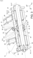
- FIG. 1 shows an agricultural spraying system 100, in particular for large-scale cultivation, such as cereal cultivation, comprising a spray boom 10 intended to spray a treatment liquid, such as phytosanitary product or liquid fertilizer, on plants to be treated in a field, according to one embodiment of the invention.
- a spray boom 10 intended to spray a treatment liquid, such as phytosanitary product or liquid fertilizer, on plants to be treated in a field, according to one embodiment of the invention.
- the spraying system 100 is in contact with the ground of the field of plants to be treated, in particular via wheels 101 allowing it to move.
- the spraying system 100 is for example self-propelled and therefore forms in itself an agricultural machine, such as a tractor. As a variant (not shown), the spraying system 100 is intended to be carried by the agricultural machine. As a further variant (not shown), the spraying system 100 is intended to be towed by an agricultural machine.
- An orthogonal reference point is adopted, without limitation, comprising a longitudinal direction X towards the front in the direction of advancement of the agricultural machine, a transverse direction Y towards the left and a vertical direction Z towards the top.
- the longitudinal and transverse directions are horizontal, generally parallel to the ground of the field of plants to be treated.
- the spray boom 10 comprises at least one assembly itself comprising a first structural element 10.1, a second structural element 10.2, as well as an anti-whipping device 10.3.
- the spray bar 10 may further comprise a central frame 11 and at least one main arm 12 mounted on the central frame 11.
- the spray bar 10 comprises, for example, two main arms 12 each mounted on the central frame 11 on an opposite side of said central frame 11 in the transverse direction Y.
- the spray bar 10 is produced symmetrically with respect to a longitudinal and vertical plane of symmetry PS centered on the central frame 11. Also, only one of the sides of this plane of symmetry PS will be described below.
- the spray bar 10 may also comprise at least one secondary arm 13 mounted in the extension of the main arm 12, the main arm 12 and one or more secondary arms 13 thus succeeding one another from the central frame 11 to a free end of the spray bar 10. The free end of the spray bar 10 is then carried by the secondary arm 13 which is the last from the central frame 11.
- the first structural element 10.1 of at least one assembly is for example formed by the central frame 11, while the second structural element 10.2 of the at least one assembly is formed by the main arm 12.
- the first structural element 10.1 of at least one assembly may also be formed by the main arm 12, while the second structural element 10.2 of the at least one assembly is formed by the secondary arm 13 mounted on the main arm 12.
- the first structural element 10.1 of at least one assembly may further be formed by one of the secondary arms 13, while the second structural element 10.2 of the at least one assembly is formed by another of the secondary arms 13 which is mounted on one of the secondary arms 13.
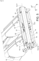
- One of the central frame 11 and the main arm 12 comprises a sheath 14 extending around a first extension axis 15, while the other of the central frame 11 and the main arm 12 comprises a shaft 16 which extends along a second extension axis 17, which is surrounded by the sheath 14 and which is pivotally mounted in the sheath 14 around the second extension axis 17.
- the central frame 11 and the main arm 12 are thus pivotally mounted relative to each other around the second extension axis 17.
- the shaft 16 passes for example through the sheath 14 from side to side.
- the sheath 14 is carried by the main arm 12, while the shaft 16 is carried by the central frame 11.
- the anti-whip device 10.3 is designed to dampen the whipping of the main arm 12 relative to the central frame 11.
- “whipping” is meant oscillations or a back-and-forth movement of the main arm 12 relative to the central frame 11, and therefore of the shaft 16 and the sheath 14 relative to each other.
- the shaft 16 and the sheath 14 oscillate around a rest position in which the shaft 16 and the sheath 14 are coaxial, the first and second extension axes 15, 17 being merged. These oscillations occur, for example, in a straight line in the event of sudden acceleration or braking of the agricultural spraying system 100, when exiting a bend or on bumpy terrain.
- the anti-whip device 10.3 is further mounted inside the sheath 14, between the shaft 16 and the sheath 14.
- the anti-whip device 10.3 is thus mounted integrally or even entirely inside the sheath 14.
- the anti-whipping device 10.3 is surrounded by the sheath 14 and surrounds the shaft 16.
- the anti-whipping device 10.3 is interposed between the shaft 16 and the sheath 14 in a first radial direction, taken relative to the first extension axis 15. In this way, the anti-whipping device 10.3 is hidden inside the sheath 14.
- the anti-whip device 10.3 is for example designed to passively dampen the whipping of the main arm 12 relative to the central frame 11. “Passively” means that the damping is carried out without the input of external energy. “External energy” means any energy other than that induced or supplied by the movement to be damped, here the whipping of the main arm 12 relative to the central frame 11. Conversely, active damping requires the input of external energy. This is for example electrical, hydraulic or pneumatic energy in the case of damping carried out by one or more cylinders.
- the anti-whip device 10.3 does not require any control or piloting to dampen the whipping of the main arm 12 relative to the central frame 11, thus simplifying its design.
- the anti-whip device 10.3 comprises for example at least one damping pad 18 and/or a ball joint 19 and/or a guide member 20.
- the or each damping pad 18 has a generally tubular shape and extends around the first and second extension axes 15, 17.
- the or each damping pad 18 surrounds the shaft 16 and is itself surrounded by the sleeve 14.
- the or each damping pad 18 is interposed in the first radial direction between the sheath 14 and the shaft 16.
- the shaft 16 passes, for example, through the or each damping pad 18 from side to side.
- the or each damping pad 18 thus makes it possible to dampen the whipping or even the oscillations of the shaft 16 and the sheath 14 relative to each other.
- the or each damping pad 18 can be mounted so as to pivot freely relative to the sheath 14 about the first extension axis 15, in particular by means of a mounting with clearance.
- the or each damping pad 18 is mounted so as to pivot securely in the sheath 14 about the first extension axis 15, in particular by means of a tight mounting.
- the or each damping pad 18 can also be mounted so as to pivot freely relative to the shaft 16 about the second extension axis 17, in particular by means of a clearance assembly.
- the shaft 16 is mounted so as to pivot securely in the damping pad(s) 18 about the second extension axis 17, in particular by means of a tight assembly.
- the anti-whiplash device 10.3 comprises, for example, two damping subassemblies each comprising at least one damping pad 18, the two damping subassemblies being arranged at a distance or being spaced apart from each other along the first extension axis 15.
- the damping subassemblies thus define a free space 21 between them.
- Each damping subassembly comprises, for example, a single damping pad 18 or two or more damping pads 18 mounted one after the other or in the extension of one another along the first extension axis 15.
- Each damping subassembly can be housed in a shoulder 22 formed at each end 23, 24 of the sheath 14 along the first extension axis 15.
- Each shoulder 22 has, for example, a stop surface which is arranged substantially perpendicular to the first extension axis 15, which is oriented in a direction opposite to the other shoulder 22, and against which the or one of the damping pads 18 of one of the damping subassemblies is arranged.
- the stop surfaces of the shoulders 22 make it possible to maintain the two damping subassemblies at distance from each other and therefore to preserve the free space 21.
- the shoulders 22 can be replaced by circlips which are housed in grooves provided at each end 23, 24 of the sheath 14 and which have the stop surfaces.
- the or each damping pad 18 comprises for example a tubular inner cage made of metal extending around the second extension axis 17 and surrounding the shaft 16, a tubular outer cage made of metal which extends around the first extension axis 15, which surrounds the inner cage and which is surrounded by the sheath 14, as well as a tube made of elastomer material interposed between the inner cage and the outer cage and mounted integrally between said inner and outer cages.
- the inner and outer cages are for example made from steel.
- the tube made of elastomer material is for example made from vulcanized rubber.
- the or each damping pad 18 may comprise only a tube made of elastomeric material, such as polyurethane, extending around the first and second extension axes 15, 17.
- the or at least one of the damping pads 18 may also comprise grooves, notches and/or recesses or alveoli provided in the tube made of elastomer material, so as to promote the movement of the sheath 14 and the shaft 16 relative to each other in the direction(s) taken radially relative to the second extension axis 17 and having such grooves, notches, recesses or alveoli. This thus makes it possible to obtain differentiated damping depending on the direction in which said damping pad 18 is stressed by the sheath 14 and the shaft 16.
- each damping subassembly comprises several damping pads 18, the damping pads 18 within each damping subassembly may have different damping properties.
- the elastomer material tubes of said damping pads 18 may for example have a different hardness and/or be loaded with fibers and/or have recesses or cells.
- the ball joint 19 is mounted between the sleeve 14 and the shaft 16.
- the shaft 16 and the sleeve 14 are thus articulated relative to each other.
- the ball joint 19 not only allows the pivoting of the shaft 16 and the sheath 14 relative to each other about the second extension axis 17, but also about axes which are perpendicular to the second extension axis 17.
- the ball joint 19 thus accompanies the oscillations of the shaft 16 and the sheath 14 relative to each other, these oscillations being, where appropriate, damped by the damping stud(s) 18.
- the ball joint 19 also allows for the forces to be taken up between the main arm 12 and the central frame 11. It prevents the structural collapse of the spray boom 10, but also the continuous crushing of the damping stud(s) 18.
- the ball joint 19 surrounds the shaft 16 and is itself surrounded by the sheath 14.
- the ball joint 19 is interposed between the sheath 14 and the shaft 16 in the first radial direction.
- the ball joint 19 comprises, for example, a nut 25 crossed by the shaft 16 and housed in a cage 26 which is mounted in the sheath 14.
- the shaft 16 is for example mounted freely pivoting in the nut 25 of the ball joint 19 around the second extension axis 17, in particular by means of a mounting with clearance.
- the cage 26 of the ball joint 19 can be mounted freely pivoting in the sheath 14 around the first extension axis 15, in particular by means of a mounting with clearance.
- the cage 26 of the ball joint 19 can still be blocked in translation in the sheath 14 along the first extension axis 15 by means of first translation blocking members, such as first circlips 27 housed in grooves provided in the sheath 14, on each side of the cage 26 along the first extension axis 15.
- first translation blocking members such as first circlips 27 housed in grooves provided in the sheath 14, on each side of the cage 26 along the first extension axis 15.
- the ball joint 19 is for example arranged in the free space 21, between the two damping sub-assemblies.
- the guide member 20 has a generally tubular shape extending around the second extension axis 17.
- the guide member 20 further surrounds the shaft 16, with which it is therefore coaxial, and is itself surrounded by the sheath 14.
- the guide member 20 is thus interposed between the sheath 14 and the shaft 16 in the first radial direction.
- the shaft 16 passes through the guide member 20, for example, from one side to the other.
- the shaft 16 is for example mounted freely pivoting in the guide member 20 around the second extension axis 17, in particular by means of a mounting with play.
- the guide member 20 is for example arranged in the free space 21, between the two damping subassemblies. Damping pads 18 of the two subassemblies damping can grip the guide member 20 along the first extension axis 15. Each end 28, 29 of the guide member 20 along the first extension axis 15 is thus in contact with the or one of the damping pads 18 of the two damping sub-assemblies along the first extension axis 15.
- the guide member 20 passes through at least one of the damping pads 18.
- the guide member 20 is thus surrounded by the damping pad(s) 18 which it passes through, interposing itself between said damping pad(s) 18 and the shaft 16.
- the or each damping pad 18 that the guide member 20 passes through can be mounted to pivot freely relative to the guide member 20 around the second extension axis 17, in particular by means of a mounting with clearance.
- the guide member 20 is mounted integrally in pivoting in the damping stud(s) 18 which it passes through around the second extension axis 17, in particular by means of a tight assembly.
- the ball joint 19 is for example mounted between the sheath 14 and the shaft 16 by means of the guide member 20, so as to articulate the shaft 16 and the sheath 14 relative to each other, by means of the guide member 20.
- the ball joint 19 thus accompanies the oscillations of the shaft 16 and the sheath 14 relative to each other, by means of the guide member 20.
- the ball joint 19 therefore surrounds the guide member 20, which itself surrounds the shaft 16.
- the ball joint 19 is thus interposed between the sheath 14 and the guide member 20 in the first radial direction.
- the nut 25 of the ball joint 19 is for example crossed by the guide member 20.
- the guide member 20 protrudes in particular on each side of the nut 25 of the ball joint 19 along the second extension axis 17.
- the guide member 20 can furthermore be mounted freely pivoting in the nut 25 of the ball joint 19 around the second extension axis 17, in particular by means of a mounting with play.
- the guide member 20 is for example blocked in translation relative to the ball joint 19 along the second extension axis 17 by means of second translation blocking members, such as second circlips 30 housed in grooves formed in the guide member 20, opposite and on each side of the nut 25 of the ball joint 19 along the second extension axis 17.
- second translation blocking members such as second circlips 30 housed in grooves formed in the guide member 20, opposite and on each side of the nut 25 of the ball joint 19 along the second extension axis 17.
- the guide member 20 makes it possible in particular to facilitate the assembly of the shaft 16 through the ball joint 19, in particular by imposing an angular movement on the pivoting of the nut 25 of the ball joint 19 around the axes perpendicular to the second extension axis 17, this angular movement preventing the nut 25 from pivoting in such a way that it can no longer be crossed by the shaft 16.
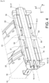
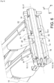
- the guide member 20 is for example mounted to pivot freely relative to the sheath 14 about a pivot axis 50, arranged perpendicular to the first extension axis 15, and pivotally integral relative to the sheath 14 about axes perpendicular to the pivot axis 50.
- the guide member 20 then forms a universal joint 51 ( figures 4 And 6 ).
- the guide member 20 not only allows the shaft 16 and the sheath 14 to pivot relative to each other about the second extension axis 17, but also about the pivot axis 50.
- the guide member 20 thus accompanies the oscillations of the shaft 16 and the sheath 14 relative to each other, these oscillations being, where appropriate, damped by the damping stud(s) 18.
- the guide member 20 also allows the forces between the main arm 12 and the central frame 11 to be taken up. It prevents the structural collapse of the spray boom 10, but also the continuous crushing of the damping stud(s) 18.
- a rod 52 passes for example through the sheath 14 and the guide member 20 along the pivot axis 50, on each side of the shaft 16.
- a lubrication circuit 53 is for example also provided, so as to ensure the pivoting of the sheath 14 and the shaft 16 relative to each other, and where appropriate, of the damping stud(s) 18 and/or the ball joint 19 and/or the guide member 20.
- the lubrication circuit 53 makes it possible to avoid problems of seizure.
- the lubrication circuit 53 comprises, for example, a first channel 54 passing right through the sleeve 14 generally in the first radial direction up to the ball joint 19, in particular the cage 26 of the ball joint 19, one or more second channels 55 passing right through the ball joint 19, in particular the nut 25 of the ball joint 19, generally in the first radial direction, as well as, where appropriate, one or more third channels 56 passing right through the guide member 20 generally in the first radial direction.
- the cage 26 of the ball joint 19 may also be provided with a groove 57 arranged around the first extension axis 15 and arranged opposite the first channel 54.
- a hydraulic lubricator 58 in particular topped with a cap, may also be mounted in the first channel 54.
- the lubrication circuit comprises a channel passing right through the shaft 16 from a first section extending along the second extension axis 17 to one or more second sections extending from the first section generally along a second radial direction, taken relative to the second extension axis 17.
- a hydraulic lubricator can also be mounted in the first section of the channel.
- the main arm 12 may comprise an elongated body 31 extending along a main extension axis 32.
- the spray ramp 10 is for example designed to occupy a spray configuration in which the main extension axis 32 of the body 31 of the main arm 12 is oriented generally transversely ( figure 1 ) and a rest configuration in which the main extension axis 32 of the body 31 of the main arm 12 is included in a generally longitudinal and vertical plane.
- the main extension axis 32 of the body 31 of the main arm 12 is included in a generally transverse and vertical plane.
- the spray boom 10 occupies for example the spraying configuration, when the agricultural spraying system 100 travels through the field of plants to be treated to spray them with treatment liquid.
- the spray boom 10 occupies for example the rest configuration while the agricultural spraying system 100 is driving on the road, the transverse size of the agricultural spraying system 100 then being reduced.
- the first extension axis 15 is for example oriented generally longitudinally, when the spray boom 10 occupies the spray configuration. Alternatively (not shown), the first extension axis 15 is oriented generally vertically, when the spray boom 10 occupies the spray configuration. In the rest configuration, the first extension axis 15 may or may not have the same orientation as in the spray configuration. It is understood by “generally longitudinally” or “generally vertically” that the first extension axis 15 is oriented longitudinally or vertically to within 10°.
- the pivot axis 50 is for example oriented generally vertically, when the spray bar 10 occupies the spray configuration. Alternatively (not shown), the pivot axis 50 is oriented generally horizontally, when the spray bar 10 occupies the spray configuration. In the rest configuration, the pivot axis 50 may or may not have the same orientation as in the spray configuration.
- generally vertically or “generally longitudinally” is meant the pivot axis 50 is oriented longitudinally or vertically to within 10°.
- the change in configuration of the spray boom 10 between its spray and rest configurations is for example achieved by pivoting the main arm 12 relative to the central frame 11 about the first extension axis 15.
- this change in configuration is achieved on the one hand by pivoting the main arm 12 relative to the central frame 11 about the first extension axis 15, and on the other hand, by pivoting a movable part of the central frame 11 carrying the sheath 14, relative to a fixed part of the central frame 11, about a pivot axis, which is neither parallel nor coincident with the first extension axis 15.
- One or more jacks 33 may also be designed to drive the main arm 12 to pivot relative to the central frame 11 around the first extension axis 15 and/or the movable part to pivot relative to the fixed part of the central frame 11 around the pivot axis.
- the or each secondary arm 13 may comprise an elongated body 35 extending along a main extension axis 36.
- the or each secondary arm 13 is for example pivotally mounted on the main arm 12 or secondary arm 13 which precedes it relative to the central frame 11 around a pivot axis 37, generally perpendicular to the first extension axis 15.
- a pivot axis 37 generally perpendicular to the first extension axis 15.
- Each secondary arm 13 may further be designed to pivot relative to the main arm 12 or secondary arm 13 preceding it, about the pivot axis 37, between an unfolded position in which the body 35 of said secondary arm 13 and the body 31, 35 of the main arm 12 or secondary arm 13 preceding it are generally aligned ( figure 1 ) with each other, in particular along the transverse direction Y in the spray configuration of the spray boom 10, and a folded position in which the body 35 of said secondary arm 13 is superimposed on the body 31, 35 of the main arm 12 or secondary arm 13 which precedes it.
- the unfolded and folded positions make it possible to vary a transverse dimension or span of the spray boom 10, when the main arm 12 occupies its spraying position, in particular depending on the dimensions of the field of plants to be treated.
- the folded position also makes it possible to reduce the size of the spray boom 10, when the main arm 12 occupies its rest position.
- One or more jacks may also be designed to pivot the or each secondary arm 13 about their pivot axis 37 between the unfolded and folded positions.
- the main arm 12 and, where appropriate, the secondary arm(s) 13 support, for example, a plurality of nozzles 38 designed to spray treatment liquid onto the plants to be treated in the field.
- the nozzles 38 are oriented generally vertically downwards.
- the nozzles 38 are further supplied with spray liquid by one or more supply lines (not shown) which may themselves be supported by the main arm 12 and, where appropriate, the secondary arm(s) 13.
- the supply line(s) are further connected to a supply circuit (not shown) drawing treatment liquid from a tank 102 supported by the agricultural spraying system 100.
- the spray bar 10 described above is particularly advantageous because it implements a space-saving and simple-design anti-whipping device 10.3.
Landscapes
- Life Sciences & Earth Sciences (AREA)
- Engineering & Computer Science (AREA)
- Insects & Arthropods (AREA)
- Pest Control & Pesticides (AREA)
- Wood Science & Technology (AREA)
- Zoology (AREA)
- Environmental Sciences (AREA)
- Catching Or Destruction (AREA)
Claims (12)
- Spritzgestängeanordnung (10) einer landwirtschaftlichen Spritzanlage (100), umfassend:- ein erstes Strukturelement (10.1),- ein zweites Strukturelement (10.2),wobei eines von dem ersten Strukturelement (10.1) und dem zweiten Strukturelement (10.2) eine Hülse (14) umfasst, die sich um eine erste Erstreckungsachse (15) erstreckt, das andere von dem ersten Strukturelement (10.1) und dem zweiten Strukturelement (10.2) eine Welle (16) umfasst, die sich entlang einer zweiten Erstreckungsachse (17) erstreckt, wobei die Welle (16) durch die Hülse (14) umgeben und in der Hülse (14) um die zweite Erstreckungsachse (17) schwenkbar montiert ist,wobei die Anordnung dadurch gekennzeichnet ist, dass sie umfasst:- eine Schlagschutzvorrichtung (10.3), die ausgelegt ist, ein Schlagen des ersten Strukturelements (10.1) und des zweiten Strukturelements (10.2) relativ zueinander zu dämpfen,
wobei die Schlagschutzvorrichtung (10.3) innerhalb der Hülse (14) zwischen der Welle (16) und der Hülse (14) montiert ist. - Anordnung nach Anspruch 1, wobei die Schlagschutzvorrichtung (10.3) ausgelegt ist, das Schlagen des ersten Strukturelements (10.1) und des zweiten Strukturelements (10.2) relativ zueinander passiv zu dämpfen.
- Anordnung nach Anspruch 1 oder 2, wobei die Schlagschutzvorrichtung (10.3) mindestens einen Dämpfungsblock (18) umfasst, wobei der oder jeder Dämpfungsblock (18) eine im Allgemeinen rohrförmige Form aufweist, die sich um die erste und die zweite Erstreckungsachse (15,17) erstreckt, wobei der oder jeder Dämpfungsblock (18) die Welle (16) umgibt und selbst durch die Hülse (14) umgeben ist.
- Anordnung nach einem der Ansprüche 1 bis 3, wobei die Schlagschutzvorrichtung (10.3) ein Kugelgelenk (19) umfasst, das zwischen der Hülse (14) und der Welle (16) montiert ist, wobei die Welle (16) somit im Inneren der Hülse (14) gelenkig gelagert ist.
- Anordnung nach einem der Ansprüche 1 bis 3, wobei die Schlagschutzvorrichtung (10.3) ein Führungselement (20) umfasst, das eine im Allgemeinen rohrförmige Form aufweist, das sich um die zweite Erstreckungsachse (17) erstreckt, wobei das Führungselement (20) die Welle (16) umgibt und selbst durch die Hülse (14) umgeben ist.
- Anordnung nach Anspruch 5, wobei die Schlagschutzvorrichtung (10.3) ein Kugelgelenk (19) umfasst, das zwischen dem Führungselement (20) und der Hülse (14) montiert ist, um die Welle (16) im Inneren der Hülse (14) über das Führungselement (20) gelenkig zu lagern.
- Anordnung nach Anspruch 5, wobei die Welle (16) in dem Führungselement (20) um die zweite Verlängerungsachse (17) frei schwenkbar montiert ist und wobei das Führungselement (20) relativ zu der Hülse (14) um eine Schwenkachse (50) frei schwenkbar montiert ist, die senkrecht zu der ersten Erstreckungsachse (15) angeordnet ist, und relativ zu der Hülse (14) um senkrechte Achsen zu der Schwenkachse (50) schwenkfest ist, wobei das Führungselement (20) somit eine Kardangelenkwelle (51) ausbildet.
- Anordnung nach einem der Ansprüche 1 bis 7, wobei die Schlagschutzvorrichtung (10.3) zwei Dämpfungsuntereinheiten umfasst, die entlang der ersten Erstreckungsachse (15) in einem Abstand voneinander angeordnet sind, wobei jede Dämpfungsuntereinheit mindestens einen Dämpfungsblock (18) umfasst, wobei jeder Dämpfungsblock (18) eine generell rohrförmige Form aufweist, die sich um die erste und die zweite Erstreckungsachse (15, 17) erstreckt, wobei jeder Dämpfungsblock (18) ferner die Welle (16) umgibt und selbst durch die Hülse (14) umgeben ist.
- Spritzgestänge (10) für eine landwirtschaftliches Spritzanlage (100), umfassend einen zentralen Rahmen (11), mindestens einen an dem zentralen Rahmen (11) montierten Hauptarm (12) und mindestens eine Anordnung nach einem der Ansprüche 1 bis 8.
- Spritzgestänge (10) nach Anspruch 9, ferner umfassend mindestens einen sekundären Arm (13), der in der Verlängerung des oder des einen der Hauptarme (12) montiert ist, wobei der Hauptarm (12) und ein oder mehrere sekundäre Arme (13) von dem zentralen Rahmen (11) bis zu einem freien Ende des Spritzgestänges (10) aufeinander folgen.
- Spritzgestänge (10) nach Anspruch 9 oder 10, wobei:- das erste Strukturelement (10.1) der mindestens einen Anordnung durch den zentralen Rahmen (11) ausgebildet wird und das zweite Strukturelement (10.2) der mindestens einen Anordnung durch den oder den einen der Hauptarme (12) ausgebildet wird;
und/oder- das erste Strukturelement (10.1) mindestens einer Anordnung durch den oder den einen der Hauptarme (12) ausgebildet wird und das zweite Strukturelement (10.2) der mindestens einen Anordnung durch den sekundären Arm (13) ausgebildet wird, der an dem Hauptarm (12) montiert ist;
und/oder
das erste Strukturelement (10.1) mindestens einer Anordnung durch einen der sekundären Arme (13) ausgebildet wird, während das zweite Strukturelement (10.2) der mindestens einen Anordnung durch einen anderen der sekundären Arme (13) ausgebildet wird, der an einem der sekundären Arme (13) montiert ist. - Landwirtschaftliche Spritzanlage (100) für eine landwirtschaftliche Maschine, umfassend ein Sprühgestänge (10) nach einem der Ansprüche 9 bis 11.
Applications Claiming Priority (1)
| Application Number | Priority Date | Filing Date | Title |
|---|---|---|---|
| FR2101558A FR3119731B1 (fr) | 2021-02-18 | 2021-02-18 | Ensemble pour rampe de pulverisation comprenant un dispositif anti-fouettement |
Publications (3)
| Publication Number | Publication Date |
|---|---|
| EP4046485A1 EP4046485A1 (de) | 2022-08-24 |
| EP4046485B1 true EP4046485B1 (de) | 2024-12-18 |
| EP4046485C0 EP4046485C0 (de) | 2024-12-18 |
Family
ID=75746826
Family Applications (1)
| Application Number | Title | Priority Date | Filing Date |
|---|---|---|---|
| EP22156522.9A Active EP4046485B1 (de) | 2021-02-18 | 2022-02-14 | Anordnung für ein spritzgestänge mit einer vorrichtung zum abmildern des peitscheneffekts |
Country Status (5)
| Country | Link |
|---|---|
| EP (1) | EP4046485B1 (de) |
| CN (1) | CN114982734A (de) |
| ES (1) | ES3010677T3 (de) |
| FR (1) | FR3119731B1 (de) |
| PL (1) | PL4046485T3 (de) |
Family Cites Families (3)
| Publication number | Priority date | Publication date | Assignee | Title |
|---|---|---|---|---|
| FR2816805B1 (fr) * | 2000-11-21 | 2003-09-26 | Exel Ind | Rampe de pulverisation avec suspension amortie |
| EP1407664B1 (de) * | 2002-09-28 | 2007-01-24 | Amazonen-Werke H. Dreyer GmbH & Co. KG | Anbauvorrichtung für das Spritzgestänge einer Feldspritze |
| FR2880770B1 (fr) * | 2005-01-20 | 2007-02-23 | Kuhn Nodet Sa Sa | Dispositif de suspension pour une rampe d'un appareil agricole d'epandage de produits |
-
2021
- 2021-02-18 FR FR2101558A patent/FR3119731B1/fr active Active
-
2022
- 2022-02-14 PL PL22156522.9T patent/PL4046485T3/pl unknown
- 2022-02-14 ES ES22156522T patent/ES3010677T3/es active Active
- 2022-02-14 EP EP22156522.9A patent/EP4046485B1/de active Active
- 2022-02-16 CN CN202210142721.0A patent/CN114982734A/zh active Pending
Also Published As
| Publication number | Publication date |
|---|---|
| ES3010677T3 (en) | 2025-04-04 |
| FR3119731B1 (fr) | 2024-05-10 |
| PL4046485T3 (pl) | 2025-03-31 |
| EP4046485C0 (de) | 2024-12-18 |
| CN114982734A (zh) | 2022-09-02 |
| FR3119731A1 (fr) | 2022-08-19 |
| EP4046485A1 (de) | 2022-08-24 |
Similar Documents
| Publication | Publication Date | Title |
|---|---|---|
| EP2099627B1 (de) | Torsionselastische achse mit aktiver steuerung des lenkwinkels unter einsatz einer hydroelastischen verbindung | |
| EP1228937B1 (de) | Vorrichtung zur steuerung der achsen eines schienenfahrzeuges | |
| WO2006002795A1 (fr) | Dispositif de suspension pour vehicule automobile | |
| EP0279135B1 (de) | Aufhängungs- und Schwenkvorrichtung von einem lenkbaren Rad eines Kraftfahrzeuges | |
| CA2401072A1 (fr) | Essieu souple pour vehicule automobile, a dispositif anti-roulis perfectionne | |
| EP4046485B1 (de) | Anordnung für ein spritzgestänge mit einer vorrichtung zum abmildern des peitscheneffekts | |
| EP0997062A1 (de) | Landmaschine | |
| WO2001070527A1 (fr) | Traverse d'essieu de vehicule avec articulations antiroulis et essieu de vehicule comportant une telle traverse | |
| FR2720337A1 (fr) | Suspension à lame de ressort transversale pour véhicule automobile. | |
| EP4256917B1 (de) | Landwirtschaftliche maschine mit sicherungssytem | |
| EP0252805B1 (de) | Hinterachse mit passiver Wirkung für Kraftfahrzeuge und Kraftfahrzeuge, ausgerüstet mit solch einer Hinterachse | |
| EP1670306B1 (de) | Heuerntemaschine mit einer transportaufhängungsvorrichtung | |
| EP4269134A1 (de) | Landwirtschaftlicher querkreuz mit verbesserter lenk- und aufhängungskopplung | |
| EP2143314B1 (de) | Verbesserter oberer Lenker | |
| EP3215377B1 (de) | Nabenträger für eine verbundlenkerachse | |
| EP4272538B1 (de) | Gesicherte heuwerbungsmaschine und methode dazu | |
| EP4347282B1 (de) | Hinterachse für ein kraftfahrzeug mit zwei hinteren längslenkern mit verbessertem elastischem verhalten | |
| BE1004400A4 (fr) | Dispositif pour monter des outils sur des engins a usage agricole. | |
| EP1632129A1 (de) | Grasmäher zum Gestrüpp-Ausreissen mit einer durch eine Stellwinde gesteuerten Lenkeinheit | |
| BE435738A (de) | ||
| EP1486118B1 (de) | Führungsvorrichtung für ein Spritzgestänge einer landwirtschaftlichen Feldspritze | |
| EP3362304B1 (de) | Anordnung zur verbindung eines achsschenkels mit einem strukturelement eines kraftfahrzeugs | |
| FR2976519A1 (fr) | Dispositif de liaison d'une roue a une structure de vehicule automobile | |
| WO2024110605A1 (fr) | Véhicule agricole comprenant un pont de stabilisation | |
| FR3101226A3 (fr) | Système de protection perfectionné pour une prise de force d’un véhicule de travail |
Legal Events
| Date | Code | Title | Description |
|---|---|---|---|
| PUAI | Public reference made under article 153(3) epc to a published international application that has entered the european phase |
Free format text: ORIGINAL CODE: 0009012 |
|
| STAA | Information on the status of an ep patent application or granted ep patent |
Free format text: STATUS: THE APPLICATION HAS BEEN PUBLISHED |
|
| AK | Designated contracting states |
Kind code of ref document: A1 Designated state(s): AL AT BE BG CH CY CZ DE DK EE ES FI FR GB GR HR HU IE IS IT LI LT LU LV MC MK MT NL NO PL PT RO RS SE SI SK SM TR |
|
| STAA | Information on the status of an ep patent application or granted ep patent |
Free format text: STATUS: REQUEST FOR EXAMINATION WAS MADE |
|
| 17P | Request for examination filed |
Effective date: 20230125 |
|
| RBV | Designated contracting states (corrected) |
Designated state(s): AL AT BE BG CH CY CZ DE DK EE ES FI FR GB GR HR HU IE IS IT LI LT LU LV MC MK MT NL NO PL PT RO RS SE SI SK SM TR |
|
| GRAP | Despatch of communication of intention to grant a patent |
Free format text: ORIGINAL CODE: EPIDOSNIGR1 |
|
| STAA | Information on the status of an ep patent application or granted ep patent |
Free format text: STATUS: GRANT OF PATENT IS INTENDED |
|
| INTG | Intention to grant announced |
Effective date: 20240801 |
|
| GRAS | Grant fee paid |
Free format text: ORIGINAL CODE: EPIDOSNIGR3 |
|
| GRAA | (expected) grant |
Free format text: ORIGINAL CODE: 0009210 |
|
| STAA | Information on the status of an ep patent application or granted ep patent |
Free format text: STATUS: THE PATENT HAS BEEN GRANTED |
|
| AK | Designated contracting states |
Kind code of ref document: B1 Designated state(s): AL AT BE BG CH CY CZ DE DK EE ES FI FR GB GR HR HU IE IS IT LI LT LU LV MC MK MT NL NO PL PT RO RS SE SI SK SM TR |
|
| REG | Reference to a national code |
Ref country code: CH Ref legal event code: EP |
|
| REG | Reference to a national code |
Ref country code: DE Ref legal event code: R096 Ref document number: 602022008705 Country of ref document: DE |
|
| REG | Reference to a national code |
Ref country code: IE Ref legal event code: FG4D Free format text: LANGUAGE OF EP DOCUMENT: FRENCH |
|
| U01 | Request for unitary effect filed |
Effective date: 20250110 |
|
| U07 | Unitary effect registered |
Designated state(s): AT BE BG DE DK EE FI FR IT LT LU LV MT NL PT RO SE SI Effective date: 20250117 |
|
| U20 | Renewal fee for the european patent with unitary effect paid |
Year of fee payment: 4 Effective date: 20250129 |
|
| REG | Reference to a national code |
Ref country code: ES Ref legal event code: FG2A Ref document number: 3010677 Country of ref document: ES Kind code of ref document: T3 Effective date: 20250404 |
|
| PG25 | Lapsed in a contracting state [announced via postgrant information from national office to epo] |
Ref country code: HR Free format text: LAPSE BECAUSE OF FAILURE TO SUBMIT A TRANSLATION OF THE DESCRIPTION OR TO PAY THE FEE WITHIN THE PRESCRIBED TIME-LIMIT Effective date: 20241218 |
|
| PGFP | Annual fee paid to national office [announced via postgrant information from national office to epo] |
Ref country code: ES Payment date: 20250317 Year of fee payment: 4 |
|
| PG25 | Lapsed in a contracting state [announced via postgrant information from national office to epo] |
Ref country code: NO Free format text: LAPSE BECAUSE OF FAILURE TO SUBMIT A TRANSLATION OF THE DESCRIPTION OR TO PAY THE FEE WITHIN THE PRESCRIBED TIME-LIMIT Effective date: 20250318 |
|
| PG25 | Lapsed in a contracting state [announced via postgrant information from national office to epo] |
Ref country code: GR Free format text: LAPSE BECAUSE OF FAILURE TO SUBMIT A TRANSLATION OF THE DESCRIPTION OR TO PAY THE FEE WITHIN THE PRESCRIBED TIME-LIMIT Effective date: 20250319 |
|
| PGFP | Annual fee paid to national office [announced via postgrant information from national office to epo] |
Ref country code: CZ Payment date: 20250211 Year of fee payment: 4 Ref country code: PL Payment date: 20250124 Year of fee payment: 4 |
|
| PG25 | Lapsed in a contracting state [announced via postgrant information from national office to epo] |
Ref country code: RS Free format text: LAPSE BECAUSE OF FAILURE TO SUBMIT A TRANSLATION OF THE DESCRIPTION OR TO PAY THE FEE WITHIN THE PRESCRIBED TIME-LIMIT Effective date: 20250318 |
|
| PG25 | Lapsed in a contracting state [announced via postgrant information from national office to epo] |
Ref country code: SM Free format text: LAPSE BECAUSE OF FAILURE TO SUBMIT A TRANSLATION OF THE DESCRIPTION OR TO PAY THE FEE WITHIN THE PRESCRIBED TIME-LIMIT Effective date: 20241218 |
|
| PG25 | Lapsed in a contracting state [announced via postgrant information from national office to epo] |
Ref country code: IS Free format text: LAPSE BECAUSE OF FAILURE TO SUBMIT A TRANSLATION OF THE DESCRIPTION OR TO PAY THE FEE WITHIN THE PRESCRIBED TIME-LIMIT Effective date: 20250418 |
|
| PG25 | Lapsed in a contracting state [announced via postgrant information from national office to epo] |
Ref country code: SK Free format text: LAPSE BECAUSE OF FAILURE TO SUBMIT A TRANSLATION OF THE DESCRIPTION OR TO PAY THE FEE WITHIN THE PRESCRIBED TIME-LIMIT Effective date: 20241218 |
|
| U1N | Appointed representative for the unitary patent procedure changed after the registration of the unitary effect |
Representative=s name: BANDPAY & GREUTER; FR |
|
| PG25 | Lapsed in a contracting state [announced via postgrant information from national office to epo] |
Ref country code: MC Free format text: LAPSE BECAUSE OF FAILURE TO SUBMIT A TRANSLATION OF THE DESCRIPTION OR TO PAY THE FEE WITHIN THE PRESCRIBED TIME-LIMIT Effective date: 20241218 |
|
| REG | Reference to a national code |
Ref country code: CH Ref legal event code: PL |
|
| PG25 | Lapsed in a contracting state [announced via postgrant information from national office to epo] |
Ref country code: CH Free format text: LAPSE BECAUSE OF NON-PAYMENT OF DUE FEES Effective date: 20250228 |
|
| PLBE | No opposition filed within time limit |
Free format text: ORIGINAL CODE: 0009261 |
|
| STAA | Information on the status of an ep patent application or granted ep patent |
Free format text: STATUS: NO OPPOSITION FILED WITHIN TIME LIMIT |
|
| 26N | No opposition filed |
Effective date: 20250919 |