EP4046358B1 - Sichere token zur steuerung des zugangs zu einer ressource in einem ressourcenverteilungsnetz - Google Patents
Sichere token zur steuerung des zugangs zu einer ressource in einem ressourcenverteilungsnetz Download PDFInfo
- Publication number
- EP4046358B1 EP4046358B1 EP20801105.6A EP20801105A EP4046358B1 EP 4046358 B1 EP4046358 B1 EP 4046358B1 EP 20801105 A EP20801105 A EP 20801105A EP 4046358 B1 EP4046358 B1 EP 4046358B1
- Authority
- EP
- European Patent Office
- Prior art keywords
- token
- meter
- global
- global token
- payment
- Prior art date
- Legal status (The legal status is an assumption and is not a legal conclusion. Google has not performed a legal analysis and makes no representation as to the accuracy of the status listed.)
- Active
Links
Images








Classifications
-
- H—ELECTRICITY
- H04—ELECTRIC COMMUNICATION TECHNIQUE
- H04L—TRANSMISSION OF DIGITAL INFORMATION, e.g. TELEGRAPHIC COMMUNICATION
- H04L63/00—Network architectures or network communication protocols for network security
- H04L63/06—Network architectures or network communication protocols for network security for supporting key management in a packet data network
- H04L63/062—Network architectures or network communication protocols for network security for supporting key management in a packet data network for key distribution, e.g. centrally by trusted party
-
- G—PHYSICS
- G06—COMPUTING OR CALCULATING; COUNTING
- G06Q—INFORMATION AND COMMUNICATION TECHNOLOGY [ICT] SPECIALLY ADAPTED FOR ADMINISTRATIVE, COMMERCIAL, FINANCIAL, MANAGERIAL OR SUPERVISORY PURPOSES; SYSTEMS OR METHODS SPECIALLY ADAPTED FOR ADMINISTRATIVE, COMMERCIAL, FINANCIAL, MANAGERIAL OR SUPERVISORY PURPOSES, NOT OTHERWISE PROVIDED FOR
- G06Q50/00—Information and communication technology [ICT] specially adapted for implementation of business processes of specific business sectors, e.g. utilities or tourism
- G06Q50/06—Energy or water supply
-
- G—PHYSICS
- G06—COMPUTING OR CALCULATING; COUNTING
- G06Q—INFORMATION AND COMMUNICATION TECHNOLOGY [ICT] SPECIALLY ADAPTED FOR ADMINISTRATIVE, COMMERCIAL, FINANCIAL, MANAGERIAL OR SUPERVISORY PURPOSES; SYSTEMS OR METHODS SPECIALLY ADAPTED FOR ADMINISTRATIVE, COMMERCIAL, FINANCIAL, MANAGERIAL OR SUPERVISORY PURPOSES, NOT OTHERWISE PROVIDED FOR
- G06Q20/00—Payment architectures, schemes or protocols
- G06Q20/08—Payment architectures
- G06Q20/085—Payment architectures involving remote charge determination or related payment systems
-
- G—PHYSICS
- G06—COMPUTING OR CALCULATING; COUNTING
- G06Q—INFORMATION AND COMMUNICATION TECHNOLOGY [ICT] SPECIALLY ADAPTED FOR ADMINISTRATIVE, COMMERCIAL, FINANCIAL, MANAGERIAL OR SUPERVISORY PURPOSES; SYSTEMS OR METHODS SPECIALLY ADAPTED FOR ADMINISTRATIVE, COMMERCIAL, FINANCIAL, MANAGERIAL OR SUPERVISORY PURPOSES, NOT OTHERWISE PROVIDED FOR
- G06Q20/00—Payment architectures, schemes or protocols
- G06Q20/38—Payment protocols; Details thereof
- G06Q20/385—Payment protocols; Details thereof using an alias or single-use codes
-
- G—PHYSICS
- G07—CHECKING-DEVICES
- G07F—COIN-FREED OR LIKE APPARATUS
- G07F15/00—Coin-freed apparatus with meter-controlled dispensing of liquid, gas or electricity
-
- G—PHYSICS
- G07—CHECKING-DEVICES
- G07F—COIN-FREED OR LIKE APPARATUS
- G07F9/00—Details other than those peculiar to special kinds or types of apparatus
- G07F9/002—Vending machines being part of a centrally controlled network of vending machines
-
- H—ELECTRICITY
- H04—ELECTRIC COMMUNICATION TECHNIQUE
- H04L—TRANSMISSION OF DIGITAL INFORMATION, e.g. TELEGRAPHIC COMMUNICATION
- H04L12/00—Data switching networks
- H04L12/02—Details
- H04L12/14—Charging, metering or billing arrangements specially adapted for data communications, e.g. authentication, authorisation and accounting [AAA] framework
- H04L12/1403—Architecture for metering, charging or billing
-
- H—ELECTRICITY
- H04—ELECTRIC COMMUNICATION TECHNIQUE
- H04L—TRANSMISSION OF DIGITAL INFORMATION, e.g. TELEGRAPHIC COMMUNICATION
- H04L12/00—Data switching networks
- H04L12/02—Details
- H04L12/14—Charging, metering or billing arrangements specially adapted for data communications, e.g. authentication, authorisation and accounting [AAA] framework
- H04L12/1403—Architecture for metering, charging or billing
- H04L12/1407—Policy-and-charging control [PCC] architecture
-
- H—ELECTRICITY
- H04—ELECTRIC COMMUNICATION TECHNIQUE
- H04L—TRANSMISSION OF DIGITAL INFORMATION, e.g. TELEGRAPHIC COMMUNICATION
- H04L12/00—Data switching networks
- H04L12/02—Details
- H04L12/14—Charging, metering or billing arrangements specially adapted for data communications, e.g. authentication, authorisation and accounting [AAA] framework
- H04L12/141—Indication of costs
- H04L12/1414—Indication of costs in real-time
- H04L12/1417—Advice of charge with threshold, e.g. user indicating maximum cost
-
- H—ELECTRICITY
- H04—ELECTRIC COMMUNICATION TECHNIQUE
- H04L—TRANSMISSION OF DIGITAL INFORMATION, e.g. TELEGRAPHIC COMMUNICATION
- H04L12/00—Data switching networks
- H04L12/28—Data switching networks characterised by path configuration, e.g. LAN [Local Area Networks] or WAN [Wide Area Networks]
- H04L12/44—Star or tree networks
-
- H—ELECTRICITY
- H04—ELECTRIC COMMUNICATION TECHNIQUE
- H04L—TRANSMISSION OF DIGITAL INFORMATION, e.g. TELEGRAPHIC COMMUNICATION
- H04L63/00—Network architectures or network communication protocols for network security
- H04L63/06—Network architectures or network communication protocols for network security for supporting key management in a packet data network
- H04L63/065—Network architectures or network communication protocols for network security for supporting key management in a packet data network for group communications
-
- H—ELECTRICITY
- H04—ELECTRIC COMMUNICATION TECHNIQUE
- H04L—TRANSMISSION OF DIGITAL INFORMATION, e.g. TELEGRAPHIC COMMUNICATION
- H04L63/00—Network architectures or network communication protocols for network security
- H04L63/06—Network architectures or network communication protocols for network security for supporting key management in a packet data network
- H04L63/068—Network architectures or network communication protocols for network security for supporting key management in a packet data network using time-dependent keys, e.g. periodically changing keys
-
- H—ELECTRICITY
- H04—ELECTRIC COMMUNICATION TECHNIQUE
- H04L—TRANSMISSION OF DIGITAL INFORMATION, e.g. TELEGRAPHIC COMMUNICATION
- H04L63/00—Network architectures or network communication protocols for network security
- H04L63/08—Network architectures or network communication protocols for network security for authentication of entities
- H04L63/0823—Network architectures or network communication protocols for network security for authentication of entities using certificates
-
- H—ELECTRICITY
- H04—ELECTRIC COMMUNICATION TECHNIQUE
- H04L—TRANSMISSION OF DIGITAL INFORMATION, e.g. TELEGRAPHIC COMMUNICATION
- H04L63/00—Network architectures or network communication protocols for network security
- H04L63/18—Network architectures or network communication protocols for network security using different networks or channels, e.g. using out of band channels
-
- H—ELECTRICITY
- H04—ELECTRIC COMMUNICATION TECHNIQUE
- H04L—TRANSMISSION OF DIGITAL INFORMATION, e.g. TELEGRAPHIC COMMUNICATION
- H04L67/00—Network arrangements or protocols for supporting network services or applications
- H04L67/01—Protocols
- H04L67/12—Protocols specially adapted for proprietary or special-purpose networking environments, e.g. medical networks, sensor networks, networks in vehicles or remote metering networks
-
- H—ELECTRICITY
- H04—ELECTRIC COMMUNICATION TECHNIQUE
- H04M—TELEPHONIC COMMUNICATION
- H04M15/00—Arrangements for metering, time-control or time indication ; Metering, charging or billing arrangements for voice wireline or wireless communications, e.g. VoIP
- H04M15/31—Distributed metering or calculation of charges
-
- H—ELECTRICITY
- H04—ELECTRIC COMMUNICATION TECHNIQUE
- H04M—TELEPHONIC COMMUNICATION
- H04M15/00—Arrangements for metering, time-control or time indication ; Metering, charging or billing arrangements for voice wireline or wireless communications, e.g. VoIP
- H04M15/83—Notification aspects
-
- H—ELECTRICITY
- H04—ELECTRIC COMMUNICATION TECHNIQUE
- H04M—TELEPHONIC COMMUNICATION
- H04M15/00—Arrangements for metering, time-control or time indication ; Metering, charging or billing arrangements for voice wireline or wireless communications, e.g. VoIP
- H04M15/83—Notification aspects
- H04M15/85—Notification aspects characterised by the type of condition triggering a notification
- H04M15/853—Calculate maximum communication time or volume
-
- H—ELECTRICITY
- H04—ELECTRIC COMMUNICATION TECHNIQUE
- H04M—TELEPHONIC COMMUNICATION
- H04M15/00—Arrangements for metering, time-control or time indication ; Metering, charging or billing arrangements for voice wireline or wireless communications, e.g. VoIP
- H04M15/83—Notification aspects
- H04M15/85—Notification aspects characterised by the type of condition triggering a notification
- H04M15/854—Available credit
-
- H—ELECTRICITY
- H04—ELECTRIC COMMUNICATION TECHNIQUE
- H04M—TELEPHONIC COMMUNICATION
- H04M15/00—Arrangements for metering, time-control or time indication ; Metering, charging or billing arrangements for voice wireline or wireless communications, e.g. VoIP
- H04M15/88—Provision for limiting connection, or expenditure
- H04M15/888—Provision for limiting connection, or expenditure severing connection after predetermined time or data
-
- H—ELECTRICITY
- H04—ELECTRIC COMMUNICATION TECHNIQUE
- H04M—TELEPHONIC COMMUNICATION
- H04M17/00—Prepayment of wireline communication systems, wireless communication systems or telephone systems
- H04M17/20—Prepayment of wireline communication systems, wireless communication systems or telephone systems with provision for recharging the prepaid account or card, or for credit establishment
-
- H—ELECTRICITY
- H04—ELECTRIC COMMUNICATION TECHNIQUE
- H04W—WIRELESS COMMUNICATION NETWORKS
- H04W12/00—Security arrangements; Authentication; Protecting privacy or anonymity
- H04W12/04—Key management, e.g. using generic bootstrapping architecture [GBA]
- H04W12/043—Key management, e.g. using generic bootstrapping architecture [GBA] using a trusted network node as an anchor
- H04W12/0431—Key distribution or pre-distribution; Key agreement
-
- H—ELECTRICITY
- H04—ELECTRIC COMMUNICATION TECHNIQUE
- H04W—WIRELESS COMMUNICATION NETWORKS
- H04W12/00—Security arrangements; Authentication; Protecting privacy or anonymity
- H04W12/04—Key management, e.g. using generic bootstrapping architecture [GBA]
- H04W12/043—Key management, e.g. using generic bootstrapping architecture [GBA] using a trusted network node as an anchor
- H04W12/0433—Key management protocols
-
- H—ELECTRICITY
- H04—ELECTRIC COMMUNICATION TECHNIQUE
- H04W—WIRELESS COMMUNICATION NETWORKS
- H04W12/00—Security arrangements; Authentication; Protecting privacy or anonymity
- H04W12/06—Authentication
- H04W12/069—Authentication using certificates or pre-shared keys
-
- H—ELECTRICITY
- H04—ELECTRIC COMMUNICATION TECHNIQUE
- H04W—WIRELESS COMMUNICATION NETWORKS
- H04W4/00—Services specially adapted for wireless communication networks; Facilities therefor
- H04W4/24—Accounting or billing
-
- H—ELECTRICITY
- H04—ELECTRIC COMMUNICATION TECHNIQUE
- H04W—WIRELESS COMMUNICATION NETWORKS
- H04W4/00—Services specially adapted for wireless communication networks; Facilities therefor
- H04W4/50—Service provisioning or reconfiguring
-
- H—ELECTRICITY
- H04—ELECTRIC COMMUNICATION TECHNIQUE
- H04W—WIRELESS COMMUNICATION NETWORKS
- H04W4/00—Services specially adapted for wireless communication networks; Facilities therefor
- H04W4/70—Services for machine-to-machine communication [M2M] or machine type communication [MTC]
-
- H—ELECTRICITY
- H04—ELECTRIC COMMUNICATION TECHNIQUE
- H04L—TRANSMISSION OF DIGITAL INFORMATION, e.g. TELEGRAPHIC COMMUNICATION
- H04L12/00—Data switching networks
- H04L12/02—Details
- H04L12/16—Arrangements for providing special services to substations
- H04L12/18—Arrangements for providing special services to substations for broadcast or conference, e.g. multicast
- H04L12/1863—Arrangements for providing special services to substations for broadcast or conference, e.g. multicast comprising mechanisms for improved reliability, e.g. status reports
-
- H—ELECTRICITY
- H04—ELECTRIC COMMUNICATION TECHNIQUE
- H04L—TRANSMISSION OF DIGITAL INFORMATION, e.g. TELEGRAPHIC COMMUNICATION
- H04L41/00—Arrangements for maintenance, administration or management of data switching networks, e.g. of packet switching networks
- H04L41/08—Configuration management of networks or network elements
- H04L41/0803—Configuration setting
- H04L41/0806—Configuration setting for initial configuration or provisioning, e.g. plug-and-play
-
- H—ELECTRICITY
- H04—ELECTRIC COMMUNICATION TECHNIQUE
- H04L—TRANSMISSION OF DIGITAL INFORMATION, e.g. TELEGRAPHIC COMMUNICATION
- H04L63/00—Network architectures or network communication protocols for network security
- H04L63/06—Network architectures or network communication protocols for network security for supporting key management in a packet data network
- H04L63/067—Network architectures or network communication protocols for network security for supporting key management in a packet data network using one-time keys
-
- H—ELECTRICITY
- H04—ELECTRIC COMMUNICATION TECHNIQUE
- H04L—TRANSMISSION OF DIGITAL INFORMATION, e.g. TELEGRAPHIC COMMUNICATION
- H04L63/00—Network architectures or network communication protocols for network security
- H04L63/10—Network architectures or network communication protocols for network security for controlling access to devices or network resources
- H04L63/108—Network architectures or network communication protocols for network security for controlling access to devices or network resources when the policy decisions are valid for a limited amount of time
-
- H—ELECTRICITY
- H04—ELECTRIC COMMUNICATION TECHNIQUE
- H04L—TRANSMISSION OF DIGITAL INFORMATION, e.g. TELEGRAPHIC COMMUNICATION
- H04L9/00—Cryptographic mechanisms or cryptographic arrangements for secret or secure communications; Network security protocols
- H04L9/08—Key distribution or management, e.g. generation, sharing or updating, of cryptographic keys or passwords
- H04L9/0891—Revocation or update of secret information, e.g. encryption key update or rekeying
-
- H—ELECTRICITY
- H04—ELECTRIC COMMUNICATION TECHNIQUE
- H04M—TELEPHONIC COMMUNICATION
- H04M15/00—Arrangements for metering, time-control or time indication ; Metering, charging or billing arrangements for voice wireline or wireless communications, e.g. VoIP
- H04M15/88—Provision for limiting connection, or expenditure
-
- H—ELECTRICITY
- H04—ELECTRIC COMMUNICATION TECHNIQUE
- H04M—TELEPHONIC COMMUNICATION
- H04M15/00—Arrangements for metering, time-control or time indication ; Metering, charging or billing arrangements for voice wireline or wireless communications, e.g. VoIP
- H04M15/88—Provision for limiting connection, or expenditure
- H04M15/881—Provision for limiting connection, or expenditure for continuing the call beyond the limit using allow grace
-
- H—ELECTRICITY
- H04—ELECTRIC COMMUNICATION TECHNIQUE
- H04W—WIRELESS COMMUNICATION NETWORKS
- H04W4/00—Services specially adapted for wireless communication networks; Facilities therefor
- H04W4/06—Selective distribution of broadcast services, e.g. multimedia broadcast multicast service [MBMS]; Services to user groups; One-way selective calling services
Definitions
- This disclosure relates generally to controlling access to a resource in a resource distribution network. More particularly, this disclosure relates to generating and applying different types of device-level secure tokens to meters in a resource distribution network to control the access to the resource.
- WO2016/168503 A1 describes secure broadcast systems and methods for Internet of Things devices.
- An encryption key is used to decode messages sent to control devices, such as devices connected by the Internet of Things.
- control devices such as devices connected by the Internet of Things.
- at least a portion of the encryption key is sent to a receiving device via a first communication technology and a remaining portion of the encryption key is sent to the receiving device via a second communication technology different or disparate from the first communication technology.
- a method that incorporates teachings of the subject disclosure may include, for example, storing, by a universal integrated circuit card (UICC) including at least one processor, a digital root certificate locking a communication device to a network provider, and disabling an activation of the communication device responsive to receiving an indication of a revocation of the stored digital root certificate from a certificate authority, wherein the indication of the revocation of the stored digital root certificate is associated with a revocation of permission for an identity authority to issue a security activation information to the communication device on behalf of the network provide.
- UICC universal integrated circuit card
- the current AMI typically does not provide payment back-up features that consider situations where there are network infrastructure issues or a customer is unable to make a payment in time. In these situations, the customer's devices will be disconnected from the resource supply regardless of any special conditions the customer may be facing.
- a system includes a headend system and a plurality of meters installed at a plurality of geographical locations and in communication with the headend system through at least a mesh network in a normal condition.
- the headend system is configured for receiving a request to issue a global token for a plurality of meters, the request specifying a time duration for the global token.
- the headend system is further configured for determining the global token based on the time duration and causing the global token to be broadcast via a broadcast network.
- the broadcast network is distinct from the mesh network.
- the global token is applicable to the plurality of meters.
- Each meter of the plurality of meters is configured for receiving and verifying the global token, determining the time duration associated with the global token, and applying the global token by connecting premises associated with the meter to a resource distribution network for at least the time duration associated with the global token.
- a method in another example, includes receiving, by a meter, a global token.
- the meter is configured to control a connection of premises associated with the meter to a resource distribution network.
- the global token is applicable to a plurality of meters including the meter and is associated with a time duration for which the premises are to be connected to the resource distribution network.
- the method further includes verifying, by the meter, the global token, determining, by the meter, the time duration associated with the global token, and applying the global token by connecting the premises associated with the meter to a resource distribution network for at least the time duration associated with the global token.
- a method includes sending, by a headend system, provisioning data to a meter via at least a mesh network.
- the provisioning data includes a global token table, and the meter is installed at a geographical location and configured to control a connection of premises associated with the meter to a resource distribution network.
- the method further includes receiving, by the headend system, a request to issue a global token associated with a time duration for a plurality of meters comprising the meter, determining, by the headend system, the global token based on the time duration, and causing the global token to be broadcast via a network distinct from the mesh network.
- the global token is usable by the meter to connect the premises to the resource distribution network based on the time duration associated with the global token.
- the meters are configured to measure the resource consumption at their respective locations and are further in communication with a headend system via a mesh network.
- the headend system is configured to generate various types of secure tokens.
- the secure tokens can include payment-based tokens, time-based tokens or global tokens.
- a payment-based token is generated in response to a payment made for a specific meter and has a credit value corresponding to the payment.
- the payment-based token can be applied at a meter to update the balance associated with the meter, which determines whether the connection to a resource supply should be maintained or disconnected.
- a time-based token is generated in response to a request made for a specific meter and has a time duration associated therewith.
- the time-based token can be applied to a meter to extend the connection with a resource supply by the time duration specified in the time-based token.
- a global token is generated for a group of meters, rather than a specific meter, and also is associated with a time duration.
- the global token can also be applied at each meter in the group of meters to extend the connection with a resource supply by the time duration specified in the global token.
- the headend system is configured to generate a payment-based token in response to receiving a request to generate a payment-based token according to a payment made for a particular meter.
- the payment-based token has a credit value corresponding to the payment.
- the credit value is a value taken from a range spanned by a negative credit value limit and a positive credit value limit.
- the headend system generates the payment-based token based on an identifier of the particular meter, such as the serial number of the meter, so that the generated payment-based token is specific to the meter.
- the payment-based token also includes the credit value.
- the headend system is further configured to transmit the payment-based token to the particular meter over the mesh network.
- the meter validates the payment-based token, such as by checking the integrity of the payment-based token, by verifying that the token is specific for the meter and by performing other operations. If the payment-based token is valid, the meter is configured to determine the balance associated with the meter based on the credit value specified in the payment-based token and connect or disconnect the resource supply at the location of the meter based on the balance associated with meter.
- the headend system is further configured to generate a time-based token in response to receiving a request to generate a time-based token for a particular meter.
- the time-based token has a time duration associated therewith, which might be requested by a user or selected by the headend system based on certain rules.
- the headend system generates the time-based token based on an identifier of the particular meter, such as the serial number of the meter, so that the generated time-based token is specific to the meter and cannot be applied at other meters.
- the headend system can transmit the time-based token to the particular meter over the network 150 and the mesh network.
- the meter After receiving the time-based token, the meter validates the time-based token in a way similar to validating the payment-based token, such as checking the integrity of the time-based token, and verifying that the token is specific for the meter. If the time-based token is valid, the meter is configured to determine the time duration associated with the meter and connect the resource supply at the location of the meter for at least the time duration specified in the time-based token.
- the headend system is also configured to generate a global token that is applicable to multiple meters associated with a certain geographic area and managed by the headend system.
- the headend system may generate the global tokens in response to a request by the utility company under a special or emergency situation, such as an extreme weather condition, where the mesh network and the headend system become unavailable.
- the global token has a time duration associated therewith.
- the global token can be distributed to users through a broadcast channel other than the mesh network, such as a radio network, a TV network, or other emergency communication mechanism, e.g. text messaging. Users of the meters can manually input the global token to their respective meters.
- a meter can determine the time duration specified by the global token and connect the resource supply at the location of the meter for the determined time duration.
- the payment-based tokens generated here are device-specific and only applicable to the specified meter. This reduces the chance of applying the payment on the wrong meter and also renders tokens intercepted by attackers useless. Furthermore, by configuring the headend system and the meters to generate and process multiple types of secure tokens, the flexibility of the resource distribution network has been significantly improved to allow it to handle different situations, including emergency situations. As a result, the meters in the distribution network do not need to switch modes for different situations, thereby reducing resource consumption, such as power, memory or computing resource, at the meters.
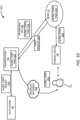
- FIG. 1 shows an illustrative operating environment 100 for generating and applying secure tokens at meters in a resource distribution network.
- the environment 100 includes a mesh network 140 associated with the resource distribution network for delivering measurement data obtained by meters in the resource distribution network.
- the mesh network 140 includes multiple meters 112A-112H (which may be referred to herein individually as a meter 112 or collectively as the meters 112) deployed at various geographical locations.
- the meters 112 can be any type of meters in a utility network, such as electricity meters, gas meters, water meters, steam meters, etc.
- the meters 112 can be implemented to measure various operating characteristics of the resource distribution network, such as characteristics of resource consumption. For example, in a power distribution network, meters 112 can monitor and measure characteristics related to power usage in the network. Example characteristics related to power usage in the resource distribution network include average or total power consumption, power surges, power outages, and load changes.
- the meters 112 transmit the collected data through the mesh network 140 to root nodes 114A and 114B (which may be referred to herein individually as a root node 114 or collectively as the root nodes 114).
- the root nodes 114 of the network 140 may be configured for communicating with the meters 112 to perform operations such as managing the meters 112, collecting data from the meters 112 and forwarding data to a headend system 104.
- a root node 114 can also be configured to function as a node to measure and process data itself.
- the root nodes 114 may be personal area network (PAN) coordinators, gateways, or any other devices capable of communicating with the headend system 104.
- PAN personal area network
- the root nodes 114 ultimately transmit the generated and collected meter data to the headend system 104 via another network 150 such as the Internet, an intranet, or any other data communication network.
- the headend system 104 can function as a central processing system that receives streams of data or messages from the root node 114.
- the headend system 104 can process or analyze the collected data. Based on the processed data, the headend system 104 further communicates with a utility system 102 associated with a utility company for various purposes, such as billing, performance analysis or troubleshooting. While FIG. 1 shows that the headend system 104 and the utility system 102 are separate systems, in some examples, they can be implemented in one system.
- a meter 112 can also be configured to control the connection of premises 132 at its geographical location or otherwise associated with the meter 112 to a resource supply 130 provided by the resource distribution network.
- the meter 112 can be configured to control the status of a switch 134 in order to connect or disconnect the power supply of the resource network from the premises 132.
- a meter 112 controls the connection of the premises 132 with the resource supply 130 (i.e. the resource distribution network) based on the mode of the meter 112.
- the meter 112 If the meter 112 is in a credit mode, the meter 112 continuously maintains the connection of the premises 132 to the resource supply 130 and measures the resource consumption at the premises 132. The meter 112 periodically sends the measured resource consumption along with other data to the headend system 104 which further forwards the data to the utility system 102 to generate bills for the user 120. If the meter 112 is in a pre-pay mode, the meter 112 controls the connection of the premises 132 to the resource supply 130 based on a credit balance associated with the meter 112 or a connection time duration specified for the meter 112.
- the meter 112 maintains the connection between the premises 132 and the resource supply 130 as long as the credit balance associated with the meter 112 is positive or exceeds a threshold balance value, or the connection time duration specified for the meter 112 is non-zero or exceeds a threshold duration value. If the balance associated with the meter 112 becomes negative or falls below the threshold balance value, or the connection time duration becomes zero, the meter 112 will control the switch 134 to disconnect the premises 132 from the resource supply 130.
- the balance or the connection time duration associated with a meter 112 can be adjusted by applying secure tokens to the meter 112. Additional details about the operations of the meter 112 in the pre-pay mode will be provided below with regard to FIGS. 2-12 .
- the meter 112 might also be coupled with a handheld device 106 that is configured to display various information associated with the meter 112 and the characteristics related to the resource.
- the handheld device 106 may be configured to show the power consumption at the premises 132, the status of the power connection (e.g. connected or disconnected), the mode of the meter (e.g. a pre-pay mode or a post-pay/credit mode), the balance associated with the meter if the meter is in a pre-pay mode, etc.
- the handheld device 106 is further configured to accept user input from a user 120 and transmit the user input to the meter 112. As will be discussed later with regard to FIGS. 2-12 , the user input may include a secure token.
- the handheld device 106 may be connected to the meter 112 in any wired or wireless manner.
- the handheld device 106 can be connected to the meter 112 through a home area network (HAN).
- HAN home area network
- suitable networking protocols for implementing a HAN include ZigBee, Bluetooth, Wi-Fi, and the like.
- Non-limiting examples of a HAN include a HomePlug network implemented via power line communications, a Multimedia over Coax Alliance (“MoCA”) network providing network connectivity between appliances and networking devices implemented via coaxial cable, a HomePNA Alliance network, etc.
- MoCA Multimedia over Coax Alliance
- FIG. 1 depicts a specific network topology (e.g., a DODAG tree), other network topologies are also possible (e.g., a ring topology, a mesh topology, a star topology, etc.).
- a ring topology e.g., a mesh topology, a star topology, etc.
- the technologies described herein can be applied by any meter in the mesh network, including the meters 112 and the root node 114 as long as the meter can control the access to a power source.
- FIG. 2 is a diagram showing an illustrative operating environment 200 for generating and applying payment-based tokens at meters in a resource distribution network, according to certain examples of the disclosure.
- the environment 200 includes the utility system 102, the headend system 104, and a meter 112 as discussed above with regard with FIG. 1 .
- the environment 200 further includes a payment processing system 206, a pre-pay vending machine 208 or a service system 210.
- the pre-pay vending machine 208 is an automated machine that allows a user 120 to make payment 212 toward a certain meter 112. Multiple pre-pay vending machines 208 can be deployed in the geographical areas where the resource distribution network is deployed so that users 120 can make payments for the meters at their respective locations.
- the service system 210 includes computing systems hosted by, for example, the utility company or a third-party entity that allows users 120 to make payments 212. For instance, the service system 210 may be configured to provide a website or a telephone service through which the user 120 can make payment 212.
- the payment processing system 206 is configured to receive the payment 212, verify the payment 212, and inform the headend system 104 or the utility system 102 regarding the payment 212.
- the payment processing system 206 may be associated with a financial institution, such as a bank or a credit union to process or verify the payment 212. Alternatively, or additionally, the payment processing system 206 may be associated with the headend system 104 or the utility system 102 and further in communication with a financial institution to process the payment 212.
- the payment 212 may be made using cash, check, credit card, debit card, and others.
- the headend system 104 is configured to first provision the meters 112 to switch their modes to the prepay mode.
- the provisioning is performed by the headend system 104 transmitting provisioning data 202 to the meters 112 that are to be switched to the prepay mode.
- the provisioning data 202 sent to a meter 112 can include a secret key used by the meter 112 to validate secure tokens received at the meter 112.
- the provisioning data 202 can further include other parameters that are used by the meter 112 to determine if a secure token is valid or not.
- the provisioning data 202 may include token acceptance parameters for determining an acceptable window for the secure tokens.
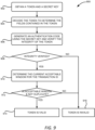
- An acceptable window defines a range of serial numbers for acceptable secure tokens. If the serial number of a received secure token falls within this range, the secure token can be accepted at the meter 112; otherwise, the meter 112 will reject the secure token. Additional details about validating a secure token are provided below with regard to FIG. 9 .
- the provisioning data 202 can also include data used by the meter 112 for processing global tokens, such as a global token table enumerating acceptable global tokens.
- the meter 112 After receiving the provisioning data 202, the meter 112 switches its mode to prepay mode and stores the provisioning data 202 locally. In some implementations, the meter 112 is also configured to send a provisioning response to the headend system 104 to inform the headend system 104 that the meter 112 has successfully switched to the prepay mode and is functioning properly under that mode. In another example, the meter 112 is set to the pre-pay mode upon installation. The meter 112 then receives the provisioning data 202 from the headend system 104 during an initial communication with the headend system 104.
- switching the mode of a meter 112 to the prepay mode can be requested by the utility company at the request of the user of the meter 112 or based on its own decision.
- the utility company can include the request to switch the mode of certain meters 112 in the token instructions 214 and send the request to the headend system 104 through the utility system 102.
- the headend system 104 determines the list of meters 112 to be switched and provisions each of these meters as discussed above.
- the secret key included in the provisioning data 202 is different from the secret key for other meters 112 and is also different from the keys used for the communication between the meter 112 and the headend system 104.
- Other parameters contained in the provisioning data 202 such as the token acceptance parameters, may be the same or different for different meters 112.
- the meter 112 can accept and process secure tokens.
- the meter 112 can accept and process payment-based tokens.
- Other types of secure tokens such as the time-based tokens and the global tokens, are discussed below with regard to FIGS. 6-12 .
- a user 120 can make a payment 212 for a meter 112 using the pre-pay vending machine 208 or the service system 210 as discussed above with regard to FIG. 1 or through other mechanisms.
- the payment processing system 206 verifies that the payment 212 is a valid payment.
- the payment processing system 206 may verify that the bank account or a credit card account used in the payment is a real account and the user 120 is an authorized user to charge the payment to the account. The payment processing system 206 will notify the user 120 if the verification process fails.
- the payment processing system 206 determines that the payment 212 is valid, the payment processing system 206 generates and sends a request for payment-based token 216 to the headend system 104.
- the request for payment-based token 216 can include information such as an identifier of the meter for which the payment-based token is to be generated, the amount of the payment 212 (also referred to herein as the "credit value" of the payment 212), whether the payment is positive or negative, and other information.
- Positive payment occurs when the payment processing system 206 determines that positive credit value is to be added to the account associated with the meter 112, e.g. when the user 120 adds X dollars to his account that is associated with the meter 112.
- Negative payment occurs when the payment processing system 206 determines that a certain credit value should be deducted from the account associated with the meter 112.
- the negative payment can be utilized, for example, to correct a positive payment previously made by mistake, to cancel a credit value adjustment made temporarily, to issue a refund to the user, and so on.
- the headend system 104 Based on the request for payment-based token 216, the headend system 104 generates a payment-based token 204.
- the payment-based token 204 is generated based on information such as the type of the token, the credit value associated with the token, the serial number of the token, the meter for which the token is generated, and so on. These types of information may be explicitly included in one or more fields of the payment-based token 204 or may be transformed before being included in the payment-based token 204.
- FIG. 3 shows an example of a payment-based token 204 generated by the headend system 104 according to certain examples of the disclosure.
- a payment-based token 204 contains 66 bits which is equivalent to 20 decimal digits.
- the first two bits of the payment-based token 204 are used to represent the token type 302. In some examples, if the value of the token type 302 is 0, then the token is a payment-based token. Other values of the token type 302 can be used to indicate other types of secure tokens.
- the next two bits of the payment-based token 204 shown in FIG. 3 indicate the sub-type 304 of the token, and the following 20 bits represent a credit value 306 which ranges from 0 - 10,000 U.S. dollars or another currency.
- the token 204 represents a positive adjustment of credit value; and if the sub-type 304 has a value 1, then the token 204 represents a negative adjustment of credit value. In other words, if the sub-type 304 shows a positive adjustment, then the amount represented by the credit value 306 will be added to the account associated with the meter 112. If the sub-type 304 shows a negative adjustment, then the amount represented by the credit value 306 will be deducted from the account associated with the meter 112.
- the payment-based token 204 shown in FIG. 3 further includes a field of transaction ID 308 that contains 10 bits.
- the transaction ID 308 represents the least significant 10 bits of a full token reference number (TRN).
- TRN is a binary number uniquely representing the sequential token number for the meter 112. After an initial starting value, each token generated for the meter 112 will have a monotonically increasing sequential TRN.
- the TRN is a 32-bit number between 0 and 4294967295 and the transaction ID 308 represents the least significant 10 bits of this 32-bit number.
- the payment-based token 204 shown in FIG. 3 also includes an integrity field 310 which is uniquely calculated by using a cryptography tool, such as the hash-based message authentication code (HMAC).
- the integrity field 310 can be generated by applying the cryptography tool to encrypt data such as fields 302-308 of the payment-based token 204, the serial number of the meter 112, the network ID of the meter 112, and information that is unique to the token within the resource distribution network, such as the TRN of the token.
- the headend system 104 generates the HMAC using a hash function such as the secure hash algorithm SHA-256 based on the secret key that is included in the provisioning data 202.
- the meter 112 can, after receiving the payment-based token 204, use the same secret key to generate the HMAC and compare the generated HMAC with that included in the integrity field 310 of the received payment-based token 204 to validate the token 204. It should be understood that cryptography tools other than HMAC and SHA-256 can also be used to generate the integrity field 310.
- the headend system 104 can send the payment-based token 204 back to the payment processing system 206 or another system which may forward it to the pre-pay vending machine 208 or the service system 210 so that the user 120 can obtain a copy of the payment-based token 204.
- the payment-based token 204 may directly send the payment-based token 204 to the pre-pay vending machine 208 or the service system 210 to provide a copy of the payment-based token 204 to the user 120.
- the payment-based token 204 may be included in an acknowledgment of the payment 212 sent to the user 120, such as in a receipt of the payment 212.
- the user 120 when submitting the payment 212 at the pre-pay vending machine 208 or at the service system 210, the user 120 is also asked whether the user wants to have the generated payment-based token 204 automatically applied to the meter 112.
- the decision made by the user 120 in this regard can be included in the request for payment-based token 216 so that the headend system 104 can act accordingly. If the user 120 agrees to the automatic application of the payment-based token 204 to the meter 112, the headend system 104 sends the payment-based token 204 to the meter 112 via the mesh network 140. If the user 120 does not agree to the automatic application of the payment-based token 204, the headend system 104 will not send the payment-based token 204 to the meter 112.
- the user 120 may choose to allow the headend system 104 to automatically apply the payment-based token 204 to the meter 112, but with a certain amount of delay. In those examples, the headend system 104 waits for the specified amount of time duration, and then sends the payment-based token 204 to the meter 112 over the mesh network 140.
- the user 120 may input the payment-based token 204 using the handheld device 106 associated with the meter 112.
- the user 120 can decline the automatic application of the payment-based token 204 by the headend system 104 and input the payment-based token 204 he or she received after making the payment 212 through the handheld device 106.
- the handheld device 106 is configured to present a user interface that allows the user 120 to enter the payment-based token 204 and to transmit the payment-based token 204 to the meter 112.
- the meter 112 Upon receiving the payment-based token 204, either from the handheld device 106 or from the headend system 104, the meter 112 starts to validate the payment-based token 204.
- the meter 112 can parse the payment-based token 204 to determine each of the fields contained in the payment-based token 204.
- the meter 112 further uses the secret key contained in the provisioning data 202 to generate an authentication code, such as the HMAC, based on the same information that is used by the headend system 104 to generate the integrity field 310.
- the information can include, for example, the serial number of the meter, the network ID of the meter, the TRN and the other fields of the payment-based token 204, i.e.
- the meter 112 can determine that the payment-based token 204 is generated by the headend system 104 and the content of the payment-based token 204 has not been altered.
- the generated payment-based token 204 is tied to the intended meter 112. As a result, if the payment-based token 204 is received by a different meter, that meter will be able to determine that the payment-based token 204 is not intended for it by determining that its calculated HMAC does not match the integrity field 310 and subsequently discard the payment-based token 204. In this way, it can be ensured that the payment-based token 204 is applied at the correct meter 112.
- the meter 112 is also configured to determine if the transaction ID of the received payment-based token 204 is within an acceptable window.
- the acceptable window can be determined based on the token acceptance parameters included in the provisioning data 202. Further details of determining the acceptable window and determining whether the payment-based token 204 is within the acceptable window are provided below with regard to FIG. 9 .
- the meter 112 may also be configured to determine if the received payment-based token 204 is a duplicate token that has been received and processed before.
- the meter 112 is configured to store the tokens or the tokens identifier (ID) 220, such as the TRNs, that the meter 112 received and processed in the past. If the current payment-based token 204 matches any of the past token IDs 220, the meter 112 can determine that the received payment-based token 204 is a duplicate and is not a valid token.
- ID tokens identifier
- the meter 112 determines that the received payment-based token 204 is a valid token, the meter 112 applies the credit value 306 to the balance of an account associated with the meter 112 according to the sub-type 304 specified in the payment-based token 204. For example, if the sub-type 304 specifies that the token is for a negative adjustment, the meter 112 reduces the balance of the account by the credit value 306; if the sub-type 304 specifies that the token is for a positive adjustment, the meter 112 increases the balance of the account by the credit value 306. Based on the balance of the account after the adjustment, the meter 112 can connect or disconnect the premises 132 from the resource supply 130.
- the meter 112 will connect the resource supply 130 to the premises 132, e.g. by closing the switch 134. If the balance associated with the meter 112 is changed from positive to negative (or from above the threshold balance to below the threshold balance), the meter 112 will disconnect the resource supply 130 from the premises 132, e.g. by opening the switch 134. If after the adjustment, the balance associated with the meter 112 remains positive or above the threshold balance (or negative or below the threshold balance), the meter 112 will maintain the connection (or the disconnection) between the premises 132 and the resource supply 130 (i.e. the resource distribution network).
- the meter 112 measures the resource consumption at the premises 132 and updates the balance associated with the meter 112 based on resource consumption. For example, the meter 112 can convert the resource consumption to a monetary value based on the rate at the time when the resource is consumed. The meter 112 then reduces the balance associated with the meter by the converted monetary amount. The meter 112 disconnects the premises 132 from the resource supply 130 once the balance becomes negative or below the threshold balance and will reconnect if a new token is received resulting in a positive balance or above the threshold balance.
- the meter 112 will generate and transmit a token application response 218 or an event message 222 to the headend system 104. If the payment-based token 204 is received from the headend system 104, the meter 112 generates a token application response 218 to report the status of the payment-based token 204 received at the meter 112. In some implementations, the token application response 218 includes the status of the payment-based token 204.
- the status of the payment-based token 204 might include, for example, "token has been applied successfully at the meter,” “token is rejected because it is outside the acceptable window,” “token is rejected because it is a duplicate,” “token is rejected because it failed integrity check,” and so on.
- the token application response 218 can further include other information, such as the credit value applied to the meter 112, the balance associated with the meter 112 after the payment-based token 204 is applied, the status of the meter switch 134 (e.g. open/disconnected or closed/connected).
- the token application response 218 may also include the payment-based token 204 or the serial number of the payment-based token 204, such as the TRN or the transaction ID.
- the token application response 218 may be sent along with other data sent from the meter 112 to the headend system 104, such as the collected meter data, or sent separately.
- the meter 112 If the payment-based token 204 is received through the handheld device 106, the meter 112 generates and transmits an event message 222 containing the payment-based token 204 to the headend system 104 to report the payment-based token 204.
- the event message 222 may also include other data, such as the status of the payment-based token 204, the status of the meter switch 134 or any other data that is included in the token application response 218. Similar to the token application response 218, the event message 222 can be sent to the headend system 104 along with other data, such as the collected meter data, or sent separately.
- the headend system 104 Upon receiving the event message 222, the headend system 104 analyzes the payment-based token 204 to determine whether the payment-based token 204 included in the event message 222 is generated by the headend system 104, such as by searching in the past tokens generated by the headend system 104. The headend system 104 is then configured to send the analysis results to the meter 112. If the analysis results show that the payment-based token 204 is not generated by the headend system 104, the meter 112 can readjust the balance associated with the meter 112 to remove the credit value of the payment-based token 204. The meter 112 may also cause the handheld device 106 to display a warning message to indicate the analysis results and the actions carried out by the meter 112 based on the analysis results.
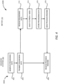
- FIG. 4 shows an example of processes for switching a meter 112 to a prepay mode and for provisioning the meter 112 so that secure tokens can be applied at the meter 112 in a resource distribution network, according to certain examples of the disclosure.
- FIG. 4 includes process 400A that illustrates aspects of the headend system 104, and process 400B that illustrates aspects of the meter 112. The processes 400A and 400B will be described together below.
- the process 400A involves the headend system 104 generating the provisioning data 202.
- the provisioning data 202 can include a secret key used by the meter 112 to validate secure tokens received at the meter 112.
- the provisioning data 202 can further include other parameters that are used by the meter 112 to determine the validity of a received secure token.
- the provisioning data 202 may include token acceptance parameters for determining an acceptable window for the secure tokens.
- the provisioning data 202 may further include a global token table listing the acceptable global tokens.
- the provisioning data 202 may also include an explicit instruction to ask the meter 112 to switch to a prepay mode.
- the headend system 104 transmits the provisioning data 202 to the meter 112 via the mesh network 140.
- the process 400B involves the meter 112 receiving the provisioning data 202.
- the meter 112 switches to the prepay mode, for example, by setting its mode to the prepay mode and loading firmware corresponding to the prepay mode for execution.
- the meter 112 stores the provisioning data 202 in memory or other storage device accessible by the meter 112.
- the meter 112 sends a provisioning response to the headend system 104 to acknowledge the receipt of the provisioning data 202 and the mode switch of the meter 112.
- the headend system 104 receives the provisioning response, and the provisioning process ends.
- provisioning is performed when the meter 112 is switched from a credit mode to a prepay mode
- the provisioning may be performed even after the meter 112 has switched to the prepay mode.
- the provisioning process may be performed whenever the headend system 104 decides to update the secret key for validating the secure tokens, the token acceptance parameters, or the global token table. In those cases, block 414 may be skipped.
- FIG. 5 shows an example of processes for generating and applying a payment-based token 204 at a meter 112 in a resource distribution network, according to certain examples of the disclosure.
- FIG. 5 includes processes 500A, 500B and 500C.
- the process 500A illustrates aspects of the headend system 104.
- the process 500B illustrates aspects of the meter 112.
- the process 500C illustrates the aspects of the handheld device 106.
- the processes 500A, 500B, and 500C will be described together below.
- the process 500A begins at block 502 where the headend system 104 receives a request for payment-based token 216 for a meter 112.
- the request for payment-based token 216 might be generated by the payment processing system 206 in response to a payment 212 made by a user 120 for the meter 112.
- the request for payment-based token 216 might be also generated by the payment processing system 206 to adjust the balance associated with the meter 112 to, for example, correct an error, issue a refund, cancel a temporary adjustment, and so on.
- the requested payment-based token 204 can be a positive adjustment or a negative adjustment.
- the process 500A involves generating a payment-based token 204 for the meter 112.
- the payment-based token 204 is generated based on an identifier of the meter 112, such as the serial number of the meter 112, the network ID of the meter 112, or a combination of these.
- the generated payment-based token 204 also includes or is based on a serial number unique to the payment-based token 204 in the mesh network 140.
- the payment-based token 204 also indicates the credit value associated with the token and the type of adjustment, such as negative adjustment or positive adjustment.
- the payment-based token 204 is generated according to the format shown in FIG.
- the integrity field is generated using a secret key to generate an HMAC based on one or more fields 302-308 of the payment-based token 204, the identifier of the meter 112, such as the serial number and the network ID, and the TRN of the payment-based token 204.
- the process 500A involves responding to the request for payment-based token 216 with the generated payment-based token 204.
- the headend system 104 sends the payment-based token 204 to the entity that requested the payment-based token 204, such as the payment processing system 206, so that the payment-based token 204 can be forwarded to the user 120.
- the headend system 104 sends the payment-based token 204 directly to the system where the user 120 made the payment, such as the pre-pay vending machine 208 or the service system 210.
- block 506 further involves applying the payment-based token 204 to the meter 112 by sending the payment-based token 204 to the meter 112.
- the application of the payment-based token 204 to the meter 112 may be performed immediately or with a certain delay, depending on the selection made by the user 120 when providing the authorization to the headend system 104 to apply the payment-based token 204.
- the process 500C involves receiving the payment-based token 204 at the handheld device 106 through user input.
- the process 500C involves sending the received payment-based token 204 to the meter 112 through, for example, a HAN.
- the process 500B involves the meter 112 receiving the payment-based token 204, either from the headend system 104 or from the handheld device 106.
- the process 500B involves validating the payment-based token 204 to determine if the received payment-based token 204 is a valid token.
- the validation process might include for example, determining the integrity of the payment-based token 204, determining that the payment-based token 204 is generated for the meter 112, determining that the token is within the acceptable window, determining the token is not a duplicate token, and so on. Additional details regarding validating the payment-based token 204 are provided below with regard to FIG. 9 .
- the process 500B involves determining whether the payment-based token 204 is a valid token. If not, the process 500B involves rejecting the payment-based token 204 at block 520. If the payment-based token 204 is a valid token, the process 500B involves, at block 518, updating the balance associated with the meter 112 based on the payment-based token 204 and connecting or disconnecting (or maintaining a connected or disconnected state with) the resource supply based on the balance. If the payment-based token 204 indicates a negative adjustment, the meter 112 reduces the balance of the meter 112 by the credit value specified in the payment-based token 204.
- the meter 112 increases the balance of the meter 112 by the credit value specified in the payment-based token 204. If the updated balance is positive (or above a threshold balance), the meter 112 connects or maintains a connection between the premises 132 to the resource supply 130. If the updated balance is negative (or below the threshold balance), the meter 112 disconnects or maintains a disconnected state between the premises 132 and the resource supply 130.
- the process 500B involves sending a token application response 218 as discussed above with regard to FIG. 2 , if the payment-based token 204 is received from the headend system 104.
- the token application response 218 includes information such as the status of the payment-based token 204 (such as accepted or rejected), the credit value applied to the meter 112, the balance associated with the meter 112 after the payment-based token 204 is applied, the status of the meter switch 134 (e.g. open/disconnected or closed/ connected), or any combination thereof.
- the token application response 218 may also include the payment-based token 204 or the serial number of the payment-based token 204, such as the TRN or the transaction ID.
- the meter 112 If the payment-based token 204 is received from the handheld device 106, the meter 112 generates and sends an event message 222 to the headend system 104 to inform the headend system 104 about the received payment-based token 204 and request the headend system 104 to verify the payment-based token 204.
- the event message 222 may contain similar content as the token application response 218, such as the status of the payment-based token 204 (such as accepted or rejected), the credit value applied to the meter 112, the balance associated with the meter 112 after the payment-based token 204 is applied, the status of the meter switch 134 (e.g. open/disconnected or closed/ connected).
- the event message 222 also includes the entire payment-based token 204 and an indication of a request for the headend system 104 to verify the authenticity of the payment-based token 204. As discussed above with regard to FIG. 2 , the token application response 218 or the event message 222 may be sent along with the meter data collected at the meter 112 or sent separately to the headend system 104.
- the headend system 104 receives the token application response 218 or the event message 222 at block 508 and processes the received message accordingly. For example, if the headend system 104 receives an event message 222, the headend system 104 verifies the payment-based token 204 contained in the event message 222 to determine if the payment-based token 204 was indeed generated by the headend system 104. The headend system 104 notifies the meter 112 about the verification results, for example, by sending a notification to the meter 112. The meter 112 can take actions according to the verification results, such as canceling the payment-based token 204 applied at the meter 112 if the payment-based token 204 is not generated by the headend system 104.
- the process 500B further involves the meter 112 sending a confirmation message to the handheld device 106 at block 524.
- the confirmation message can include, for example, the status of the payment-based token 204 (e.g. accepted or rejected), the credit value applied to the meter 112, the balance associated with the meter 112 after the payment-based token 204 is applied, the status of the meter switch 134 (e.g. open/disconnected or closed/ connected).
- the handheld device 106 receives the confirmation message at block 534 and presents it to the user 120 in a user interface.
- a meter 112 is generally configured to disconnect the premises 132 from the resource supply 130 if the balance associated with the meter 112 is below zero or below a threshold balance value.
- the user 120 of the premises 132 needs to make timely payment and have the payment-based token applied at the meter 112 in order not to be disconnected from the resource supply 130.
- the user 120 can request a time-based token to extend the connection with the resource supply 130 for a certain time duration and make a payment at a later time.
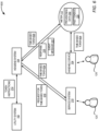
- FIG. 6 is a diagram showing an illustrative operating environment 600 for generating and applying time-based tokens at meters in a resource distribution network, according to certain examples of the disclosure.
- the environment 600 includes the utility system 102, the headend system 104, meters 112, and the service system 210 as discussed above with regard with FIGS. 1 and 2 .
- the service system 210 includes computing systems hosted by, for example, the utility company or a third-party entity to allow users 120 to make payments 212. Additionally, or alternatively, the service system 210 can also be configured to allow users 120 to request time-based tokens. For instance, the service system 210 may provide a website or a telephone service through which the user 120 can request time-based tokens.
- the service system 210 can generate and transmit a request for time-based token 616 to the headend system 104.
- the request for time-based token 616 can include data such as the identifier of the meter 112 for which the time-based token is to be generated, the time duration associated with the time-based token, the starting date of the duration, etc.
- the payment processing system 206 might communicate with the utility system 102.
- the utility system 102 can then communicate with the headend system 104 to request the time-based token to be generated, such as by sending the request for time-based token 616 to the headend system 104.
- the headend system 104 Based on the request for time-based token 616, the headend system 104 generates a time-based token 604.
- the time-based token 604 is generated based on information such as the type of the token, the time duration associated with the token, the date on which the time duration starts, the serial number of the device, the meter for which the token is generated, and so on. These types of information may be explicitly included in one or more fields of the time-based token 604 or may be transformed before being included in the time-based token 604.
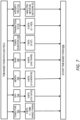
- FIG. 7 shows an example of a time-based token 604 generated by the headend system 104 according to certain examples of the disclosure.
- a time-based token 604 contains 66 bits which is equivalent to 20 decimal digits. As such the size of the time-based token 604 is the same as the size of the payment-based token 204 shown in FIG. 3 . Similar to the payment-based token 204, the first two bits of the time-based token 604 is also used to represent the token type 702. In some examples, if the value of the token type 702 is 1, then the token is a time-based token. Other values of the token type 702 can be used to indicate other types of secure tokens.
- the next 15 bits of the time-based token 604 shown in FIG. 7 indicate the starting date of the time duration associated with the time-based token 604. For example, 5 and 4 bits of the 15 bits can be used to represent the day 704 and month 706 of the starting date, respectively. Six bits of the 15 bits can be used to represent the lower two digits of the year 708 of the starting date.
- the time-based token 604 shown in FIG. 7 further includes a token duration 710 which is represented by 7 bits to define the time duration associated with the token 604 which can be any value between 1 and 127 days.
- the time duration associated with the time-based token 604 may be specified in the request for time-based token 616. In other examples, the time duration might be determined or adjusted by the headend system based on certain rules. For instance, the rule might specify that the time duration cannot be more than 7 days for a user who first requests the time-based token 604, and can be no more than 5 days for a user who requests the time-based token 604 for the second time. The maximum time duration that a user can request for the time-based token 604 decreases as the number of times the user requests for the time-based token 604 increases. Other types of rules might also be utilized.
- the time-based token 604 shown in FIG. 7 further includes a 10-bit field of transaction ID 712.
- the transaction ID 712 represents the least significant 10 bits of the full TRN which is a binary number uniquely representing the sequential token number for the meter 112. After an initial starting value, each token generated for the meter 112, whether it is a payment-based token or a time-based token, will have a monotonically increasing sequential TRN.
- the TRN is a 32-bit number between 0 and 4294967295 and the transaction ID 712 represents the least significant 10 bits of this 32-bit number.
- the time-based token 604 shown in FIG. 7 also includes an integrity field 714 which is uniquely calculated using a cryptography tool, such as the hash-based message authentication code (HMAC).
- HMAC hash-based message authentication code
- the integrity field 714 of the time-based token 604 can be generated by applying the cryptography tool to encrypt data such as one or more of fields 702 - 710 of the time-based token 604, the serial number of the meter 112, the network ID of the meter 112, and information that is unique to the token within the resource distribution network, such as the TRN of the token.
- the headend system 104 generates the HMAC using a hash function such as the secure hash algorithm SHA-256 based on the secret key that is included in the provisioning data 202.
- the meter 112 can, after receiving the time-based token 604, use the same secret key to generate the HMAC and compare the generated HMAC with that included in the integrity field 714 of the received time-based token 604 to validate the token.
- the validation includes, for example, determining the integrity and the authenticity of the payment-based token 204. It should be understood that cryptography tools other than HMAC or other than SHA-256 can also be used to generate the integrity field 714.
- the headend system 104 sends the time-based token 604 back to the system that requested for the time-based token 604, such as the service system 210.
- the user 120 can thus obtain a copy of the generated time-based token 604.
- the user 120 can apply the time-based token 604 at the meter 112 using the handheld device 106 without relying on the headend system 104.
- the handheld device 106 can be configured to present a user interface that allows the user 120 to enter the time-based token 604 and to transmit the time-based token 604 to the meter 112
- the user 120 can request to have the time-based token 604 to be applied automatically by the headend system 104 to the meter 112. Such a request can be included in the request for time-based token 616 so that the headend system 104 can act accordingly. If the user 120 requests the automatic application of the time-based token 604, the headend system 104 sends the time-based token 604 to the meter 112 via the mesh network 140. If the user 120 does not request the automatic application of the time-based token 604, the headend system 104 will not send the time-based token 604 to the meter 112. In some examples, the user 120 may choose to allow the headend system 104 to automatically apply the time-based token 604 to the meter 112 with a certain amount of delay. In those examples, the headend system 104 waits for the specified amount of delay duration, and then sends the time-based token 604 to the meter 112 over the mesh network 140.
- the meter 112 can validate the time-based token 604.
- the meter 112 can parse the time-based token 604 to determine each field contained in the time-based token 604.
- the meter 112 further uses the secret key contained in the provisioning data 202 to generate an authentication code, such as the HMAC, based on the same information that is used by the headend system 104 to generate the integrity field 714.
- the information can include, for example, the serial number of the meter, the network ID of the meter, the TRN and the other fields of the time-based token 604, such as the token type 702, the starting date (fields 704-708), the token duration 710, and the transaction ID 712. If the generated authentication code matches the integrity field 714 of the time-based token 604, the meter 112 can determine that the time-based token 604 is generated by the headend system 104 and the content of the time-based token 604 has not been altered.
- the time-based token 604 is made specific to the intended meter 112.
- a meter can determine whether a received time-based token 604 is a proper token by determining whether the calculated authentication code matches the integrity field 714 or not, and only apply the time-based token 604 that is intended for it.
- validating the received time-based token 604 also includes determining whether the time-based token 604 is within an acceptable window and whether it is a duplicate token that has been received and processed before. Further details of determining the acceptable window and determining whether the time-based token 604 is within the acceptable window are provided below with regard to FIG. 9 .
- the meter 112 determines that the received time-based token 604 is not a valid token, the meter 112 rejects or denies the time-based token 604. Otherwise, the meter 112 connects the premises 132 at the geographical location of the meter 112 to the resource supply 130 starting from the start date and for the time duration specified in the time-based token 604. After the specified time duration has passed, the meter 112 remain connected or disconnect the resource supply 130 based on the balance associated with the meter 112. In other words, if the balance is negative or below a threshold balance value, the meter 112 disconnects the premises 132 from the resource supply 130; otherwise, the meter 112 continues to connect the premises 132 with the resource supply 130.
- the meter 112 will generate and transmit a token application response 218 or an event message 222 to the headend system 104 depending on where the meter 112 received the time-based token 604. If the time-based token 604 is received from the headend system 104, the meter 112 generates a token application response 218 to report the status of the time-based token 604 received at the meter 112.
- the token application response 218 includes the status of the time-based token 604, such as "token has been applied successfully at the meter,” “token is rejected because it is outside the acceptable window,” “token is rejected because it is a duplicate,” “token is rejected because it failed integrity check,” and so on.
- the token application response 218 can further include other information, such as the time duration applied at the meter 112, or the status of the meter switch 134 (e.g. open/disconnected or closed/connected).
- the token application response 218 may also include the time-based token 604 or the serial number of the time-based token 604, such as the TRN or the transaction ID.
- the token application response 218 may be sent along with other data sent from the meter 112 to the headend system 104, such as the collected meter data, or sent separately.
- the meter 112 If the time-based token 604 is received through the handheld device 106, the meter 112 generates and transmits an event message 222 containing the time-based token 604 to the headend system 104 to report the time-based token 604.
- the event message 222 may also include other data, such as the status of the time-based token 604, the status of the meter switch 134 or any other data that is included in the token application response 218.
- the event message 222 can also be sent to the headend system 104 along with other data, such as the collected meter data, or sent separately.
- the headend system 104 Upon receiving the event message 222, the headend system 104 analyzes the time-based token 604 to determine whether the time-based token 604 included in the event message 222 was generated by the headend system 104, such as by searching in the past tokens generated by the headend system 104. The headend system 104 is then configured to send the analysis results to the meter 112. If the analysis results show that the time-based token 604 was not generated by the headend system 104, the meter 112 can disconnect the resource supply 130 and update the balance associated with the meter to reflect the resource consumption that occurred during the connection. The meter 112 may also cause the handheld device 106 to display a warning message to indicate the analysis results and the actions carried out by the meter 112 based on the analysis results.
- FIG. 8 shows an example of processes for generating and applying a time-based token 604 at a meter 112 in a resource distribution network, according to certain examples of the disclosure.
- FIG. 8 includes processes 800A, 800B, and 800C.
- the process 800A illustrates aspects of the headend system 104.
- the process 800B illustrates aspects of the meter 112.
- the process 800C illustrates the aspects of the handheld device 106.
- the processes 800A, 800B, and 800C will be described together below.
- the process 800A begins at block 802 where the headend system 104 receives a request for time-based token 616 for a meter 112. As discussed above with regard to FIG. 6 , the request for time-based token 616 might be generated by the service system 210 in response to a request by a user 120. At block 804, the process 800A involves generating a time-based token 604 for the meter 112. To make the time-based token 604 specific to the meter 112, the headend system 104 generates the time-based token 604 based on an identifier of the meter 112, such as the serial number of the meter 112, the network ID of the meter 112, or a combination thereof.
- an identifier of the meter 112 such as the serial number of the meter 112, the network ID of the meter 112, or a combination thereof.
- the generated time-based token 604 also includes or is based on a serial number unique to the time-based token 604 in the mesh network 140, such as the TRN.
- the time-based token 604 also indicates the time duration for the meter 112 to connect the resource supply 130 to the premises 132 as well as the starting date of the time duration.
- the time-based token 604 is generated according to the format shown in FIG. 7 , which includes a token type 702, a start date 704-708, a token duration 710, a transaction ID 712 and an integrity field 714.
- the integrity field 714 is generated by using a secret key to generate an HMAC based on one or more of the fields 702-712 of the time-based token 604, the identifier of the meter 112, such as the serial number and the network ID, and the TRN of the payment-based token 204.
- the process 800A involves responding to the request for time-based token 616 with the generated time-based token 604.
- the headend system 104 sends the time-based token 604 to the entity that requested the time-based token 604, such as the service system 210. If the user 120 authorizes the headend system 104 to automatically apply the generated time-based token 604 to the meter 112, block 806 further involves applying the time-based token 604 to the meter 112 by sending the time-based token 604 to the meter 112.
- the application of the payment-based token 204 to the meter 112 may be performed immediately or with a certain delay, depending on the selection made by the user 120 when providing the authorization to the headend system 104 to apply time-based token 604.
- the process 800C involves receiving the time-based token 604 at the handheld device 106 through user input.
- the process 800C involves sending the received time-based token 604 to the meter 112 through, for example, a HAN.
- the process 800B involves the meter 112 receiving the time-based token 604, either from the headend system 104 or from the handheld device 106.
- the process 800B involves validating the time-based token 604 to determine if the received time-based token 604 is a valid token.
- the validation process might include for example, determining the integrity of the time-based token 604, determining that the time-based token 604 is generated for the meter 112, determining that the token is within the acceptable window, determining the token is not a duplicate token, and so on. Additional details regarding validating the time-based token 604 are provided below with regard to FIG. 9 .
- the process 800B involves determining whether the time-based token 604 is a valid token based on the validation result obtained in block 814. If not, the process 800B involves rejecting the time-based token 604 at block 820. If the time-based token 604 is a valid token, the process 800B involves, at block 818, connecting the resource supply 130 starting from the start date specified in the time-based token 604 and for the time duration indicated in the token duration field 710.
- the process 800B involves sending a token application response 218 as discussed above with regard to FIG. 6 , if the time-based token 604 is received from the headend system 104.
- the token application response 218 includes information such as the status of the time-based token 604 (such as accepted or rejected), the time duration specified in the time-based token 604, the status of the meter switch 134 (e.g. open/disconnected or closed/ connected), or other information.
- the token application response 218 may also include the time-based token 604 or the serial number of the time-based token 604, such as the TRN or the transaction ID.
- the meter 112 If the time-based token 604 is received from the handheld device 106, the meter 112 generates and sends an event message 222 to the headend system 104 to inform the headend system 104 about the received time-based token 604 and requests the headend system 104 verify the time-based token 604.
- the event message 222 may contain similar content as the token application response 218, such as the status of the payment-based token 204, the time duration specified in the time-based token 604, the status of the meter switch 134 (e.g. open/disconnected or closed/ connected) and so on.
- the event message 222 also includes the entire time-based token 604 and a request for the headend system 104 to verify the authenticity of the time-based token 604.
- the token application response 218 or the event message 222 may be sent along with the meter data collected at the meter 112 or sent separately to the headend system 104.
- the headend system 104 receives the token application response 218 or the event message 222 at block 808 and processes the received message accordingly. For example, if the headend system 104 receives an event message 222, the headend system 104 verifies the payment-based token 204 contained in the event message 222 to determine if the time-based token 604 was indeed generated by the headend system 104. The headend system 104 notifies the meter 112 about the verification results, for example, by sending a notification to the meter 112. The meter 112 can take actions according to the verification results, such as disconnecting the resource supply 130 from the premises 132 if the time-based token 604 is not generated by the headend system 104.
- the process 800B further involves the meter 112 sending a confirmation message to the handheld device 106 at block 824.
- the confirmation message can include, for example, the status of the time-based token 604 (e.g. accepted or rejected), the time duration and the start date specified in the time-based token 604, the status of the meter switch 134 (e.g. open/disconnected or closed/ connected) and the like.
- the handheld device 106 receives the confirmation message at block 834 and presents it to the user 120 in a user interface.
- FIG. 9 shows an example of a process 900 for validating a secure token at a meter 112, according to certain examples of the disclosure.
- the secure token can be a payment-based token 204 or a time-based token 604.
- the process 900 can be used to implement block 514 of the process 500B or block 814 of the process 800B.
- the meter 112 e.g., the meter in the environment 100, 200 or 600 implements operations depicted in FIG. 9 by executing suitable program code.
- the process 900 is described with reference to certain examples depicted in the figures. Other implementations, however, are possible.
- the process 900 involves obtaining a secure token, such as the payment-based token 204 described above with regard to FIGS. 2-5 or the time-based token 604 described above with regard to FIGS. 6-8 .
- the process 900 further involves obtaining a secret key from the provisioning data 202.
- the headend system 104 includes a secret key in the provisioning data 202 sent to the meter 112 during the provisioning process.
- the secret key is used by the headend system 104 to generate the integrity field of the secure token.
- the process 900 involves decoding the secure token to determine the individual fields contained in the secure token. For example, if the secure token is formatted as shown in FIG. 3 or 7 , the meter 112 may determine the type of the secure code by examining the first two bits of the secure token, which shows the token type. If the token type is 0, then the meter 112 can determine that the secure token is a payment-based token 204; if the token type is 1, then the meter 112 can determine that the secure token is a time-based token 604.
- the meter 112 can decode the rest of the fields of the token, such as the sub-type 304, the credit value 306, the transaction ID 308 of the payment-based token 204, the integrity field 310, or the starting date 704-708, the token duration 710, transaction ID 712 and the integrity field 714 of the time-based token 604.
- the process 900 involves generating an authentication code for the secure token using the secret key and verifying the integrity of the token based on the authentication code.
- the meter 112 can generate the authentication code in the same way as the headend system 104 generates the integrity field 310 or 714 and using the same secret key.
- the headend system 104 generates the integrity field of the secure token by generating an HMAC based on the other fields of the secure token, the serial number of the meter 112, the network ID of the meter 112, and the TRN of the secure token and using SHA-256 algorithm.
- the meter 112 can apply the same cryptograph algorithm using the same secret key on the decoded version of the same fields, and other corresponding information available at the meter 112, such as the serial number of the meter 112, the network ID of the meter 112. If the generated authentication code matches the data contained in the integrity field of the received secure token, the meter 112 can determine that the secure token is intended for the meter 112 and has not been altered. Otherwise, the integrity verification of the secure token has failed.
- the process 900 involves determining whether the integrity of the secure token has been verified based on the comparison results obtained at block 906. If not, the meter 112 can determine that the secure token is invalid. If the meter 112 has successfully verified the integrity of the secure token, the meter 112 can continue to examine other aspects of the secure token to determine its validity.
- the process 900 involves determining the current acceptable window for the TRN or transaction ID (TID) of the secure token. If the TRN or the transaction ID of the secure token falls within the acceptable window, then the meter 112 can accept the secure token; otherwise, the meter 112 will reject the secure token.
- the meter 112 can determine the acceptable window based on the token acceptance parameters in the provisioning data 202.
- the token acceptance parameters include a TID F , a TID POS and a TID NEG .
- the TID F represents a floor value of acceptable TIDs. In other words, the lowest TID that is acceptable at the meter 112 is TID F .
- TID POS represents the largest positive offset of an acceptable TID compared to a current acceptable TID, TID current .
- TID NEG represents the largest negative offset of an acceptable TID compared to the TID current .
- the TID POS and TID NEG define an acceptable window for the TID of a received secure token, i.e. [ TID current - TID NEG , TID current + TID POS ] .
- the TID current - TID NEG defines the lower boundary of the acceptable window
- TID current + TID POS defines the upper boundary of the acceptable window.
- the acceptable window can be reformulated as: max TID F , TID current ⁇ TID NEG , TID current + TID POS .
- the current acceptable TID, TID current is updated by the meter 112 based on the received secure tokens.
- the TID current is set to be the highest TID of the secure tokens that have been previously received at the meter 112, including both the payment-based token 204 and the time-based token 604. If the currently received secure token has a TID falling inside this acceptable window, the meter 112 can determine that the secure token is acceptable; otherwise, the secure token is unacceptable.
- TID current is 10
- TID POS is 5
- TID NEG is 3
- TID F is 4, the acceptable window becomes [7, 15].
- Any secure token with a TID lower than 7 or higher than 15 is not acceptable at the meter 112 at this moment. This mechanism prevents the order of the secure tokens being applied from deviating too significantly from the order of the TRNs generated for the secure tokens.
- the acceptable window of [7, 15] ensures that the TID of an acceptable secure token is close to 10, a TID that has been accepted at the meter 112.
- the TID is used to determine the acceptable window for the secure token, and the TID is a truncated version of the full TRN of the secure token, such as the 10 least significant bits of the TRN.
- the TID will return to 0 and start increasing one by one.
- the meter 112 can be configured to recognize this scenario, and adjust the acceptable window accordingly. For example, the meter 112 might determine the lower boundary of the acceptable window to be 1021 and the upper boundary of the acceptable window to be 3. In this example, any token with a TID falling within [1021, 1022, 1023, 0, 1, 2, 3] is acceptable.
- the process 900 involves determining whether the TID of the received secure token falls within the acceptable window.
- the meter 112 further determines whether the secure token is a duplicate token that has been received and applied before.
- the meter 112 can access the past token IDs 220 stored at the meter 112 to detect duplication. If the meter 112 determines that the TID of the secure token is outside the acceptable window or that the secure token has been applied before, the meter 112 determines, at block 916, that the secure token is invalid. Otherwise, the meter 112 determines, at block 914, that the secure token is a valid token.
- the headend system 104 is available for the generation of the payment-based tokens or time-based tokens, communicating with the meters 112 to apply secure tokens at the meters 112, etc.
- the mesh network 140 might become unavailable or unstable and the headend system 104 might become unavailable, such as in an extreme weather condition or natural disaster. In these situations, it would be impossible for users 120 to make payment to request payment-based tokens or to request time-based tokens.
- the headend system 104 is further configured to issue global tokens.
- a global token is a type of secure token that is not specific to any meter 112.
- the same global token can be applied at multiple meters 112 in the mesh network 140.
- Each global token has a time duration associated therewith instructing the meter 112 to keep the resource supply 130 connected for that time duration.
- users 120 can have access to resource supply even if the headend system 104 becomes unavailable to generate tokens based on user requests.
- FIG. 10 shows an illustrative operating environment 1000 for generating and applying global tokens at meters 112 in a resource distribution network, according to certain examples of the disclosure.
- the environment 1000 includes the utility system 102, the headend system 104, and the meters 112 and their associated handheld devices 106 as discussed above with regard with FIGS. 1-9 .
- FIG. 10 shows one of the meters 112 in the resource distribution network.
- the utility company might determine that a special situation has arisen, such as the weather forecast shows an extreme weather condition is coming, and the headend system 104 might become unavailable for a period of time.
- the utility company can decide to issue a global token to the meters 112 in the network by sending a global token request 1002 to the headend system 104 through the utility system 102.
- the global token request 1002 can specify the time duration associated with the global token.
- the headend system 104 can generate or otherwise obtain a global token 1004 that is associated with the specified time duration. In some implementations, the headend system 104 generates the global token 1004 in response to the global token request 1002. In other implementations, the global token 1004 is obtained from a global token table 1010 stored at a location that is accessed by the headend system 104. In one example, the global token table 1010 includes a list of global tokens that are acceptable by the meters 112. Each of the global tokens in the global token table 1010 is mapped to a time duration. As such, the headend system 104 can retrieve the corresponding global token 1004 based on the time duration specified in the global token request 1002.
- FIG. 11 shows an example of the global token table 1010, according to certain examples of the disclosure.
- the global token table 1010 includes a list of global tokens 1108A-1 108K. For each global token in this list, there is a time duration 1104 associated therewith.
- global token 1 in the example shown in FIG. 11 has a time duration of 1 day; global token 2 has a time duration of 2 days; and the global token N has a time duration of M number of days.
- M can be any positive integer, such as 127.
- the global token table 1010 also have an application flag 1106 for each global token in the table to indicate whether the corresponding global token has been applied or used or not. For example, if global token 2 has been used last time when there was a hurricane in the area, the application flag for global token 2 can be set to YES indicating that this global token has been used. As such, each time when the headend system 104 issues a global token, the headend system 104 will select a global token from the global token table 1010 that corresponds to the requested time duration and that has not been used before.
- One benefit of only allowing a global token to be used once is to prevent fraud and misuse of the token.
- the example of the global token table 1010 shown in FIG. 11 is for illustration purpose only and should not be construed as limiting.
- the global token table 1010 may be constructed in any other formats.
- the global token table 1010 may include only the global token and the corresponding time duration without the application flag. In such a scenario, whether a global token has been used or not may be indicated using other mechanisms.
- FIG. 12 shows an example of a global token 1004 that can be applied at a meter 112 in a resource distribution network, according to certain examples of the disclosure.
- a global token 1004 contains 66 bits which is equivalent to 20 decimal digits.
- the size of the global token 1004 is the same as the size of the time-based token 604 shown in FIG. 7 and is the same as the size of the payment-based token 204 shown in FIG. 3 .
- the first two bits of the global token 1004 is used to represent the token type 1202. In some examples, if the value of the token type 1202 is 3, then the token is a global token. Other values of the token type can be used to indicate other types of secure tokens.
- the next 64 bits of the global token 1004 shown in FIG. 12 contains a random number that uniquely identifies the global token 1004.
- the global token table 1010 is generated at the headend system 104 by generating the global tokens 1004 and their corresponding time durations.
- the global token table 1010 is generated by the utility system 102 or another system associated with the utility company and transmitted to the headend system 104. In either case, the headend system 104 also transmits the global token table 1010 to the meters 112 via the mesh network 140.
- the global token table 1010 can be transmitted to each meter 112 in the corresponding provisioning data 202 transmitted to the meter 112. In other implementations, the global token table 1010 is transmitted to the meter 112 separately from the provisioning data 202.
- the headend system 104 can retrieve a global token 1004 as specified in the global token request 1002.
- the headend system 104 further causes the global token 1004 to be broadcast through a broadcast network 1008.
- the broadcast network 1008 is different from the mesh network 140 because the mesh network 140 might have already become unavailable or unstable.
- the broadcast network 1008 may be a radio network, a TV network, an Internet, a cellular network, or any other type of networks that can be utilized to broadcast the global token 1004 so that users 120 can be notified about the global token 1004.
- the user 120 can input the global token 1004 to the meter 112, such as through the handheld device 106.
- the meter 112 verifies the received global token 1004 by determining if the received global token 1004 is included in the global token table 1010 and has not been used before. If so, the meter 112 can determine that the global token 1004 is a valid token. Otherwise, the global token 1004 is an invalid token and is rejected by the meter 112.
- the meter 112 determines that a global token has been used before by checking the application flag 1106 associated with the global token 1004 in the global token table 1010. If the application flag 1106 indicates that the global token 1004 has not been used before, the meter 112 applies the global token 1004 at the meter 112 by connecting the resource supply 130 for the time duration associated with the global token 1004. The meter 112 also updates the application flag 1106 for the global token 1004 in the global token table 1010 to indicate that this global token 1004 has now been used.
- the meter 112 can transmit an event message 1012 to the headend system 104 to report the global token 1004 processed by the meter 112.
- the event message 1012 might include the global token 1004 received by the meter 112 and other data, such as the status of the global token 1004 (applied or rejected), the time duration specified in the global token 1004, the time when the global token 1004 was applied, the status of the meter switch 134 and so on.
- the event message 1012 can be sent separately to the headend system 104 or along with other data sent from the meter 112, such as the meter data collected by the meter 112.
- the headend system 104 After receiving the event message 1012, the headend system 104 analyzes the global token 1004 included in the event message 1012 to determine whether the global token 1004 was generated or issued by the headend system 104, such as by searching the global token table 1010. The headend system 104 is then configured to send the analysis results to the meter 112. If the analysis results show that the global token 1004 was not properly issued by the headend system 104, the meter 112 can disconnect the resource supply 130 and update the balance associated with the meter 112 to reflect the resource consumption that occurred during the time duration when the connection was established. The meter 112 may also cause the handheld device 106 to display a warning message to indicate the analysis results and the actions carried out by the meter 112 based on the analysis results.
- each global token 1004 is allowed to be used once. As such, after a global token 1004 is issued, the headend system 104 will label such a global token 1004 as having been used and thus will not use it again. After all or a portion of the global tokens in the current global token table 1010 have been used, the headend system 104 or the utility system 102 or another system associated with the utility company can generate a new global token table 1010 containing a different set of global tokens.
- a global token table 1010 is configured to be acceptable for a given period of time and the global tokens contained in the global token table 1010 may only be used during that period of time. As such, a new global token table 1010 can also be generated for another period of time if the current period of time has expired.
- the headend system 104 stores the new global token table 1010 and also transmits the new global token table 1010 to the meters 112 in the mesh network 140 to replace the existing global token table 1010. Thereafter, the next global token 1004 will be selected from the new global token table 1010 based on the time duration specified in the global token request 1002.
- FIG. 13 shows an example of processes for issuing and applying a global token at a meter, according to certain examples of the disclosure.
- the example shown in FIG. 13 assumes that the global token table 1010 has been generated and stored at the headend system 104 and has been transmitted to the meters 112 in the mesh network 140.
- FIG. 13 includes processes 1300A, 1300B and 1300C.
- the process 1300A illustrates aspects of the headend system 104.
- the process 1300B illustrates aspects of the meter 112.
- the process 1300C illustrates the aspects of the handheld device 106.
- the processes 1300A, 1300B, and 1300C will be described together below.
- the process 1300A begins at block 1302 where the headend system 104 determines a global token 1004 based on a global token request 1002. In one example, the headend system 104 determines the global token 1004 by selecting a global token from the global token table 1010 that has a time duration as specified in the global token request 1002 and has not been used before. At block 1304, the process 1300A involves causing the global token 1004 to be broadcast through one or more broadcast networks 1008.
- the process 1300C begins at block 1312, where the handheld device 106 receives the global token 1004 through user input using, e.g. a keyboard or an image scanning device.
- the process 1300C involves sending the global token 1004 to the meter 112.
- the process 1300B begins at block 1322, where the meter 112 receives the global token 1004 from the handheld device 106.
- the process 1300B involves verifying the global token 1004 and further involves determining the time duration associated with the global token 1004.
- the meter 112 verifies the global token 1004 by determining whether the global token 1004 is listed in the global token table 1010. The meter 112 further determines whether the global token 1004 has been used before, for example, by examining the application flag 1106 for the global token 1004 in the global token table 1010.
- the meter 112 determines that the global token 1004 is listed in the global token table 1010 and has not been used before, the meter 112 determines that the global token 1004 is a valid token; otherwise, the meter 112 rejects the global token 1004 as an invalid token.
- the process 1300B involves, after determining that the global token 1004 is a valid token, connecting the premises 132 to the resource supply 130 for the time duration associated with the global token 1004.
- the meter 112 further updates the application flag associated with the global token 1004 to indicates that the global token 1004 has been applied at the meter 112.
- the process 1300C involves sending a confirmation message to the handheld device 106 to indicate the status of the global token 1004, such as being applied or rejected.
- the handheld device 106 receives that confirmation message at block 1316 and presents it to the user 120 through a user interface.
- the process 1300B involves generating and sending an event message 1012 to the headend system 104. This occurs after the mesh network 140 and the headend system 104 are recovered and become available.
- the event message 1012 can include the global token 1004 received by the meter 112, the status of the global token 1004 (applied or rejected), the time duration specified in the global token 1004, the time when the global token 1004 was applied, the status of the meter switch 134 and so on.
- the headend system 104 receives the event message 1012 and processes the event message 1012 to determine if the global token 1004 contained in the message is indeed issued by the headend system 104.
- the headend system 104 may also determine if the global token 1004 was applied during the period of time when the global token table 1010 was acceptable. As described above in detail with regard to FIG. 10 , additional actions will be taken at the meter 112 if the headend system 104 determines that the global token 1004 was not issued properly by the headend system 104.
- FIG. 14 shows an example of a process 1400 for receiving and processing a secure token at a meter, according to certain examples of the disclosure.
- One or more nodes or meters of the mesh network 140 implement operations depicted in FIG. 14 by executing suitable program code.
- the process 1400 is described with reference to certain examples depicted in the figures. Other implementations, however, are possible.
- the process 1400 involves receiving a secure token.
- the secure token may be a payment-based token 204, a time-based token 604, or a global token 1004.
- the secure token may be received from the headend system 104 via the mesh network 140 or from the handheld device 106 via a HAN or other connections.
- the process 1400 involves decoding the secure token to determine the type of the secure token. For example, if the token formats for the three types of secure tokens follow those shown in FIGS. 3 , 7 and 12 , the meter 112 can determine the type of the secure token by examining the first two bits of the received token. In the examples shown in FIGS. 3 , 7 and 12 , if the value of first two bits of the token is 0, then the token is a payment-based token 204; if the value is 1, then the token is a time-based token 604; and if the value is 3, then the token is a global token 1004.
- the process 1400 involves different operations. If the secure token is a payment-based token 204, the process 1400 involves, at block 1406, processing the secure token according to process 500B discussed above with regard to FIG. 5 . If the secure token is a time-based token 604, the process 1400 involves, at block 1408, processing the secure token according to process 800B discussed above with regard to FIG. 8 . If the secure token is a global token 1004, the process 1400 involves, at block 1410, processing the secure token according to process 1300B discussed above with regard to FIG. 13 .
- a user of cellular resource can either request a payment-based token by making a payment to his account or request a time-based token using a service system, such as a service system.
- a service system such as a service system.
- IMEI international mobile equipment identify
- a global token might be generated and broadcast to users of the cellular resource in cases where the system responsible for generating the secure tokens becomes unavailable. In those cases, users can input the global token to their cellphones to continue using the cellular resource. Access to other resources, such as network resources, online computing resources, online storage resources, can also be controlled in a similar way.
- Fig. 15 illustrates an exemplary meter 1500 that can be employed to implement the secure token processing mechanism described herein, such as a meter 112 or a root node 114.
- the meter 1500 includes a communication module 1516 and a metrology module 1518 connected through a local or serial connection 1530. These two modules may be housed in the same unit on separate boards hence the local connection 1530 may be an on-board socket. Alternatively, the modules may be housed separately and thus the local connection 1530 may be a communication cable, such as a USB cable, or another conductor. Since these two components may be physically separate, the communication module 1516 and the metrology module 1518 may be removed or replaced independently of each other.
- the function of the communication module 1516 includes receiving and sending messages, including the secure tokens, through the mesh network 140.
- the function of the metrology module 1518 includes the functions necessary to manage the resource, in particular, to allow access to the resource and to measure the resource used.
- the communication module 1516 may include a communication device 1512 such as an antenna and a radio. Alternatively, the communication device 1512 may be any device that allows wireless or wired communication.
- the communication module 1516 may also include a processor 1513, and memory 1514.
- the communication device 1512 is used to receive and send messages through the network 140.
- the processor 1513 controls functions performed by the communication module 1516.
- the memory 1514 may be utilized to store data used by the processor 1513 to perform its function.
- the memory 1514 may also store the data contained in the provisioning data 202, such as the secret key and the acceptance parameters.
- the metrology module 1518 may include a processor 1521, memory 1522, and measurement circuitry 1523.
- the processor 1521 in the metrology module 1518 controls functions performed by the metrology module 1518.
- the memory 1522 stores data needed by the processor 1521 to perform its functions, such as the global token table 1010 used to validate a global token.
- other data in the provisioning data 202 is also stored in the memory 1502 of the metrology module 1518, rather than in the memory 1514 of the communication module 1516.
- the communication module 1516 and the metrology module 1518 communicate with each other through the local connection 1530 to provide data needed by the other module.
- the measurement circuitry 1523 handles the measuring of the resource and may also handle the recording of measurements taken.
- Both the communication module 1516 and the metrology module 1518 may include computer-executable instructions stored in memory or in another type of computer-readable medium and one or more processors within the modules may execute the instructions to provide the functions described herein.
- FIG. 16 depicts an example of the computing system 1600.
- the implementation of computing system 1600 could be used for the headend system 104.
- the depicted example of a computing system 1600 includes a processor 1602 communicatively coupled to one or more memory devices 1604.
- the processor 1602 executes computer-executable program code stored in a memory device 1604, accesses information stored in the memory device 1604, or both.
- Examples of the processor 1602 include a microprocessor, an application-specific integrated circuit ("ASIC"), a field-programmable gate array (“FPGA”), or any other suitable processing device.
- the processor 1602 can include any number of processing devices, including a single processing device.
- a memory device 1604 includes any suitable non-transitory computer-readable medium for storing program code 1605 (e.g. the code used for generating the payment-based tokens or the time-based tokens), program data 1607 (e.g. the global token table), or both.
- a computer-readable medium can include any electronic, optical, magnetic, or other storage device capable of providing a processor with computer-readable instructions or other program code.
- Non-limiting examples of a computer-readable medium include a magnetic disk, a memory chip, a ROM, a RAM, an ASIC, optical storage, magnetic tape or other magnetic storage, or any other medium from which a processing device can read instructions.
- the instructions may include processor-specific instructions generated by a compiler or an interpreter from code written in any suitable computer-programming language, including, for example, C, C++, C#, Visual Basic, Java, Python, Perl, JavaScript, and ActionScript.
- the computing system 1600 executes program code 1605 that configures the processor 1602 to perform one or more of the operations described herein.
- Examples of the program code 1605 include, in various embodiments, the program code used to generate the payment-based tokens, the program code used to generate the time-based tokens, the program code used to verify the payment-based tokens, time-based tokens or global tokens, or other suitable applications that perform one or more operations described herein.
- the program code may be resident in the memory device 1604 or any suitable computer-readable medium and may be executed by the processor 1602 or any other suitable processor.
- one or more memory devices 1604 stores program data 1607 that includes one or more datasets described herein. Examples of these datasets include past secure tokens, the global token table, etc.
- one or more of data sets, models, and functions are stored in the same memory device (e.g., one of the memory devices 1604).
- one or more of the programs, data sets, models, and functions described herein are stored in different memory devices 1604 accessible via a data network.
- One or more buses 1606 are also included in the computing system 1600. The buses 1606 communicatively couples one or more components of a respective one of the computing system 1600.
- the computing system 1600 also includes a network interface device 1610.
- the network interface device 1610 includes any device or group of devices suitable for establishing a wired or wireless data connection to one or more data networks.
- Non-limiting examples of the network interface device 1610 include an Ethernet network adapter, a modem, and/or the like.
- the computing system 1600 is able to communicate with one or more other computing devices (e.g., the root nodes 114) via a data network using the network interface device 1610.
- the computing system 1600 may also include a number of external or internal devices, an input device 1620, a presentation device 1618, or other input or output devices.
- the computing system 1600 is shown with one or more input/output ("I/O") interfaces 1608.
- An I/O interface 1608 can receive input from input devices or provide output to output devices.
- An input device 1620 can include any device or group of devices suitable for receiving visual, auditory, or other suitable input that controls or affects the operations of the processor 1602.
- Non-limiting examples of the input device 1620 include a touchscreen, a mouse, a keyboard, a microphone, a separate mobile computing device, etc.
- a presentation device 1618 can include any device or group of devices suitable for providing visual, auditory, or other suitable sensory output.
- Non-limiting examples of the presentation device 1618 include a touchscreen, a monitor, a speaker, a separate mobile computing device, etc.
- FIG. 16 depicts the input device 1620 and the presentation device 1618 as being local to the computing device that executes the headend system 104, other implementations are possible.
- one or more of the input device 1620 and the presentation device 1618 can include a remote client-computing device that communicates with the computing system 1600 via the network interface device 1610 using one or more data networks described herein.
- a computing device can include any suitable arrangement of components that provide a result conditioned on one or more inputs.
- Suitable computing devices include multipurpose microprocessor-based computer systems accessing stored software (i.e., computer-readable instructions stored on a memory of the computer system) that programs or configures the computing system from a general-purpose computing apparatus to a specialized computing apparatus implementing one or more aspects of the present subject matter. Any suitable programming, scripting, or other type of language or combinations of languages may be used to implement the teachings contained herein in software to be used in programming or configuring a computing device.
- aspects of the methods disclosed herein may be performed in the operation of such computing devices.
- the order of the blocks presented in the examples above can be varied; for example, blocks can be re-ordered, combined, and/or broken into sub-blocks. Certain blocks or processes can be performed in parallel.
Landscapes
- Engineering & Computer Science (AREA)
- Computer Networks & Wireless Communication (AREA)
- Signal Processing (AREA)
- Business, Economics & Management (AREA)
- Computer Security & Cryptography (AREA)
- Computing Systems (AREA)
- Accounting & Taxation (AREA)
- General Physics & Mathematics (AREA)
- Physics & Mathematics (AREA)
- General Engineering & Computer Science (AREA)
- Computer Hardware Design (AREA)
- Health & Medical Sciences (AREA)
- Theoretical Computer Science (AREA)
- General Business, Economics & Management (AREA)
- Strategic Management (AREA)
- General Health & Medical Sciences (AREA)
- Finance (AREA)
- Economics (AREA)
- Medical Informatics (AREA)
- Human Resources & Organizations (AREA)
- Water Supply & Treatment (AREA)
- Public Health (AREA)
- Marketing (AREA)
- Primary Health Care (AREA)
- Tourism & Hospitality (AREA)
- Computer And Data Communications (AREA)
- Financial Or Insurance-Related Operations Such As Payment And Settlement (AREA)
- Data Exchanges In Wide-Area Networks (AREA)
- Management, Administration, Business Operations System, And Electronic Commerce (AREA)
Claims (15)
- System, das Folgendes umfasst:
ein Headend-System (104), konfiguriert zum:Empfangen einer Anforderung zum Ausgeben eines globalen Tokens (1004, 1108) für eine Vielzahl von Zählern (112), wobei die Anforderung eine Zeitdauer (1104) für das globale Token (1004, 1108) angibt;Bestimmen des globalen Tokens (1004, 1108) auf der Basis der Zeitdauer (1104), wobei das globale Token (1004, 1108) auf die Vielzahl von Zählern (112) anwendbar ist; undBewirken, dass das globale Token (1004, 1108) über ein Broadcast-Netzwerk (1008) rundgesendet wird; undeine Vielzahl von Zählern (112), die an einer Vielzahl von geographischen Orten installiert und in einem normalen Zustand über mindestens ein Maschennetzwerk (140) mit dem Headend-System (104) in Verbindung sind, wobei sich das Broadcast-Netzwerk (1008) von dem Maschennetzwerk (140) unterscheidet, wobei jeder Zähler (112A-H) der Vielzahl von Zählern (112) konfiguriert ist zum:Empfangen und Verifizieren des globalen Tokens (1004, 1108);Bestimmen der mit dem globalen Token (1004, 1108) assoziierten Zeitdauer (1104); undAnwenden des globalen Tokens (1004, 1108) durch Verbinden von mit dem Zähler (112) assoziierten Räumlichkeiten (132) mit einem Ressourcenverteilungsnetzwerk für mindestens die mit dem globalen Token (1004, 1108) assoziierte Zeitdauer (1104). - System nach Anspruch 1, wobei das Headend-System (104) ferner zum Senden, vor der Erzeugung des globalen Tokens (1004, 1108), von Provisionierungsdaten (202) über mindestens das Maschennetzwerk (140) zu der Vielzahl von Zählern (112) konfiguriert ist, wobei die Provisionierungsdaten (202) eine Globale-Token-Tabelle (1010) umfassen.
- System nach Anspruch 2, wobei die Globale-Token-Tabelle (1010) eine Liste von an der Vielzahl von Zählern (112) akzeptablen globalen Token (1102) und eine mit jedem globalen Token (1108A-K) in der Liste von globalen Token (1010) assoziierte Zeitdauer (1104) umfasst, und
wobei das Verifizieren des globalen Tokens (1004, 1108) das Feststellen umfasst, dass das globale Token (1004, 1108) in der Liste von globalen Tokens (1010) ist, wobei das Bestimmen der mit dem globalen Token (1004, 1108) assoziierten Zeitdauer (1104) das Nachschlagen in der Globale-Token-Tabelle umfasst, um die Zeitdauer (1104) zu bestimmen. - System nach Anspruch 3, wobei jedes globale Token (1004, 1108) in der Liste von globalen Tokens (1010) einmal verwendet wird, und wobei der Zähler (112) ferner zum Aktualisieren, nach dem Anwenden des globalen Tokens (1004, 1108), eines Anwendungsflags (1106) für das globale Token (1004, 1108) konfiguriert ist, um anzugeben, dass das globale Token (1004, 1108) in der Globale-Token-Tabelle (1010) verwendet wurde.
- System nach Anspruch 1, wobei der Zähler (112) ferner konfiguriert ist zum:Bestimmen, als Reaktion auf die Feststellung, dass die mit dem globalen Token (1004, 1108) assoziierte Zeitdauer (1104) abgelaufen ist, eines mit dem Zähler (112) assoziierten Saldos; undTrennen der mit dem Zähler (112) assoziierten Räumlichkeiten (132) von dem Ressourcenverteilungsnetzwerk als Reaktion auf die Feststellung, dass der mit dem Zähler (112) assoziierte Saldo unter einem Schwellenwert liegt.
- System nach Anspruch 1, wobeidas globale Token (1004, 1108) von einer mit dem Zähler (112) gekoppelten Vorrichtung (106) aus empfangen wird; undder Zähler (112) ferner konfiguriert ist zum:
Erzeugen und Übertragen einer Ereignismeldung (222, 1012) zum Headend-System (104) über mindestens das Maschennetzwerk (140), wobei die Ereignismeldung (222, 1012) das globale Token (1004, 1108) umfasst. - System nach Anspruch 6, wobei das Headend-System (104) ferner konfiguriert ist zum:Verifizieren, als Reaktion auf den Empfang der Ereignismeldung (222, 1012), dass das in der Ereignismeldung (222, 1012) angegebene globale Token (1004, 1108) vom Headend-System (104) erzeugt wurde;Übertragen, als Reaktion auf die Feststellung, dass das in der Ereignismeldung (222, 1012) angegebene globale Token (1004, 1108) nicht vom Headend-System (104) erzeugt wurde, einer Benachrichtigung zum Zähler (112), die angibt, dass das globale Token (1004, 1108) nicht vom Headend-System (104) erzeugt wurde; undwobei der Zähler (112) ferner konfiguriert ist zumAnzeigen, als Reaktion auf den Empfang der Benachrichtigung, die angibt, dass das globale Token (1004, 1108) nicht vom Headend-System (104) erzeugt wurde; undTrennen der mit dem Zähler (112) assoziierten Räumlichkeiten (132) von dem Ressourcenverteilungsnetzwerk.
- Verfahren, das Folgendes umfasst:Empfangen, durch einen Zähler (112A-H), eines globalen Tokens (1004, 1108), wobei der Zähler (112A-H) zum Steuern einer Verbindung von mit dem Zähler (112A-H) assoziierten Räumlichkeiten (132) mit einem Ressourcenverteilungsnetzwerk konfiguriert ist, wobei das globale Token (1004, 1108) auf eine Vielzahl von den Zähler (112A-H) umfassenden Zählern (112) anwendbar und mit einer Zeitdauer (1104) assoziiert ist, für die die Räumlichkeiten (132) mit dem Ressourcenverteilungsnetzwerk verbunden werden sollen;Verifizieren des globalen Tokens (1004, 1108) durch den Zähler (112A-H);Bestimmen, durch den Zähler (112A-H), der mit dem globalen Token (1004, 1108) assoziierten Zeitdauer (1104); undAnwenden des globalen Tokens (1004, 1108) durch Verbinden der mit dem Zähler (112A-H) assoziierten Räumlichkeiten (132) mit einem Ressourcenverteilungsnetzwerk für mindestens die mit dem globalen Token (1004, 1108) assoziierte Zeitdauer (1104).
- Verfahren nach Anspruch 8, wobei das Bestimmen der mit dem globalen Token (1004, 1108) assoziierten Zeitdauer (1104) auf der Basis einer Globale-Token-Tabelle (1010) erfolgt, und wobei die Globale-Token-Tabelle (1010) von einem Headend-System (104) aus über mindestens ein Maschennetzwerk (140) vor dem Empfangen des globalen Tokens (1004, 1108) empfangen wird.
- Verfahren nach Anspruch 8, wobei die Globale-Token-Tabelle (1010) eine Liste von an der Vielzahl von Zählern (112) akzeptablen globalen Token (1102) und eine Zeitdauer (1104) umfasst, die mit jedem globalen Token (1108A-K) in der Liste von globalen Token (1010) assoziiert ist, und wobei das Verifizieren des globalen Tokens (1108A-K) das Bestimmen umfasst, dass das globale Token (1108A-K) in der Liste von globalen Token (1102) ist, und wobei jedes globale Token (1108A-K) in der Liste von globalen Token (1102) einmal verwendet wird, und wobei der Zähler (112A-H) ferner zum Aktualisieren, nach dem Anwenden des globalen Tokens (1108A-K), eines Anwendungsflags (1106) für das globale Token (1108A-K) konfiguriert ist, um anzugeben, dass das globale Token (1108A-K) in der Globale-Token-Tabelle (1010) verwendet wurde.
- Verfahren nach Anspruch 10, das ferner Folgendes umfasst:Bestimmen auf der Basis der Globale-Token-Tabelle (1010), vor dem Anwenden des globalen Tokens (1108A-K), ob das globale Token (1108A-K) zuvor verwendet wurde; undZurückweisen des globalen Tokens (1108A-K) als Reaktion auf die Feststellung, dass das globale Token (1108A-K) zuvor verwendet wurde; undEmpfangen einer zweiten Globale-Token-Tabelle vom Headend-System (104) über mindestens das Maschennetzwerk (140), wobei die zweite Globale-Token-Tabelle eine zweite Liste von globalen Token und eine mit jedem globalen Token der zweiten Liste von globalen Token assoziierte Zeitdauer umfasst, und wobei die zweite Liste von globalen Token sich von der Liste von globalen Token (1102) unterscheidet.
- Verfahren nach Anspruch 8, das ferner das Bestimmen, als Reaktion auf die Feststellung, dass die mit dem globalen Token (1004, 1108) assoziierte Zeitdauer (1104) abgelaufen ist, eines mit dem Zähler (112A-H) assoziierten Saldos umfasst; undTrennen der mit dem Zähler (112A-H) assoziierten Räumlichkeiten (132) von dem Ressourcenverteilungsnetzwerk als Reaktion auf die Feststellung, dass der mit dem Zähler (112A-H) assoziierte Saldo unter einem Schwellenwert liegt, oderwobei das globale Token (1004, 1108) von einer mit dem Zähler (112H) gekoppelten Vorrichtung (106) aus empfangen wird; und wobei das Verfahren ferner Folgendes umfasst:
Erzeugen und Übertragen einer Ereignismeldung (222, 1012) an ein Headend-System (104) zur Verifizierung des globalen Tokens (1004, 1108), wobei die Ereignismeldung (222, 1012) das globale Token (1004, 1108) umfasst. - Verfahren, das Folgendes umfasst:Senden, durch ein Headend-System (104), von Provisionierungsdaten (202), die eine Globale-Token-Tabelle (1010) umfassen, zu einem Zähler (112) über mindestens ein Maschennetzwerk (140), wobei der Zähler (112) an einem geografischen Ort installiert und zum Steuern einer Verbindung von mit dem Zähler (112) assoziierten Räumlichkeiten (132) mit einem Ressourcenverteilungsnetzwerk konfiguriert ist;Empfangen, durch das Headend-System (104), einer Anforderung zum Ausgeben eines globalen Tokens (1004, 1108), das mit einer Zeitdauer (1104) für mehrere den Zähler (112) umfassende Zähler assoziiert ist;Bestimmen, durch das Headend-System (104), des globalen Tokens (1004, 1108) auf der Basis der Zeitdauer (1104); undBewirken, dass das globale Token (1004, 1108) über ein Netzwerk (1008) rundgesendet wird, das sich von dem Maschennetzwerk (140) unterscheidet, wobei das globale Token (1004, 1108) vom Zähler (112) zum Verbinden der Räumlichkeiten (132) mit dem Ressourcenverteilungsnetzwerk auf der Basis der mit dem globalen Token (1004, 1108) assoziierten Zeitdauer (1104) verwendet werden kann.
- Verfahren nach Anspruch 13, wobei die Globale-Token-Tabelle (1010) eine Liste von an der Vielzahl von Zählern (112) akzeptablen globalen Token (1102) und eine mit jedem globalen Token (1108A-K) in der Liste von globalen Token (1102) assoziierte Zeitdauer (1104) umfasst, und
wobei das Bestimmen des globalen Tokens (1004, 1108) auf der Basis der Zeitdauer (1104) durch Nachschlagen in der Globale-Token-Tabelle (1010) durchgeführt wird, um das globale Token (1004, 1108) auf der Basis der Zeitdauer (1104) zu bestimmen. - Verfahren nach Anspruch 14, das ferner Folgendes umfasst:Verifizieren, als Reaktion auf den Empfang einer Ereignismeldung (222, 1012) von dem Zähler (112), die ein bestimmtes globales Token umfasst, dass das in der Ereignismeldung (222, 1012) angegebene bestimmte globale Token vom Headend-System (104) ausgegeben wurde; undÜbertragen, als Reaktion auf die Feststellung, dass das bestimmte globale Token nicht vom Headend-System (104) ausgegeben wurde, einer Benachrichtigung zum Zähler (112), die angibt, dass das globale Token (1004, 1108) nicht vom Headend-System (104) ausgegeben wurde, wobei die Benachrichtigung den Zähler (112) veranlasst, die Räumlichkeiten (132) vom Ressourcenverteilungsnetzwerk zu trennen.
Applications Claiming Priority (2)
| Application Number | Priority Date | Filing Date | Title |
|---|---|---|---|
| US16/656,718 US11481852B2 (en) | 2019-10-18 | 2019-10-18 | Secure tokens for controlling access to a resource in a resource distribution network |
| PCT/US2020/055635 WO2021076668A1 (en) | 2019-10-18 | 2020-10-14 | Secure tokens for controlling access to a resource in a resource distribution network |
Publications (2)
| Publication Number | Publication Date |
|---|---|
| EP4046358A1 EP4046358A1 (de) | 2022-08-24 |
| EP4046358B1 true EP4046358B1 (de) | 2023-11-29 |
Family
ID=73060122
Family Applications (1)
| Application Number | Title | Priority Date | Filing Date |
|---|---|---|---|
| EP20801105.6A Active EP4046358B1 (de) | 2019-10-18 | 2020-10-14 | Sichere token zur steuerung des zugangs zu einer ressource in einem ressourcenverteilungsnetz |
Country Status (7)
| Country | Link |
|---|---|
| US (1) | US11481852B2 (de) |
| EP (1) | EP4046358B1 (de) |
| JP (1) | JP7282986B2 (de) |
| AU (1) | AU2020367793B2 (de) |
| BR (1) | BR112022007286A2 (de) |
| CA (1) | CA3157850C (de) |
| WO (1) | WO2021076668A1 (de) |
Families Citing this family (3)
| Publication number | Priority date | Publication date | Assignee | Title |
|---|---|---|---|---|
| US11481851B2 (en) | 2019-10-18 | 2022-10-25 | Landis+Gyr Innovations, Inc. | Secure tokens for controlling access to a resource in a resource distribution network |
| EP3901804B1 (de) * | 2020-04-24 | 2022-08-17 | Secure Thingz Limited | Bereitstellungssteuerungsvorrichtung, system und verfahren |
| US12045375B2 (en) * | 2020-08-24 | 2024-07-23 | Analog Devices, Inc. | Techniques of tracking software usage on a remote device |
Family Cites Families (29)
| Publication number | Priority date | Publication date | Assignee | Title |
|---|---|---|---|---|
| US7236950B2 (en) * | 1998-10-29 | 2007-06-26 | Universal Card Services Corp. | Method and system of combined billing of multiple accounts on a single statement |
| US6747571B2 (en) * | 1999-03-08 | 2004-06-08 | Comverge Technologies, Inc. | Utility meter interface system |
| WO2000058922A1 (en) | 1999-03-26 | 2000-10-05 | Merlin Gerin S.A. (Proprietary) Limited | Utility purchases by prepayment |
| JP2001356025A (ja) | 2000-06-15 | 2001-12-26 | Tokyo Gas Co Ltd | プリペイド方式の検針メータ、プリペイド検針システム及びプリペイド検針方法 |
| US7181017B1 (en) * | 2001-03-23 | 2007-02-20 | David Felsher | System and method for secure three-party communications |
| US7693797B2 (en) | 2004-06-21 | 2010-04-06 | Nokia Corporation | Transaction and payment system security remote authentication/validation of transactions from a transaction provider |
| CN100397945C (zh) | 2004-11-19 | 2008-06-25 | 华为技术有限公司 | 空闲模式下防止消息重放攻击的方法 |
| JP4658718B2 (ja) | 2005-07-04 | 2011-03-23 | 矢崎総業株式会社 | ガス供給システム |
| KR100653139B1 (ko) | 2005-07-21 | 2006-12-05 | 주식회사 미래테크놀로지 | 시간동기 방식 오티피 시스템의 오티피 토큰 시간보정에의한 인증방법 |
| US20070083479A1 (en) * | 2005-09-14 | 2007-04-12 | Swartz Stephen B | Method, apparatus and program storage device for providing a prepaid metering system |
| US8639922B2 (en) * | 2009-06-01 | 2014-01-28 | Dhananjay S. Phatak | System, method, and apparata for secure communications using an electrical grid network |
| US8667060B2 (en) * | 2010-11-23 | 2014-03-04 | General Electric Company | Data collection from utility meters over advanced metering infrastructure |
| JP2012113670A (ja) * | 2010-11-29 | 2012-06-14 | Renesas Electronics Corp | スマートメータ及び検針システム |
| EP2515552A1 (de) * | 2011-04-18 | 2012-10-24 | Nagravision S.A. | Überwachungsmodul für sicheren EVU-Zähler |
| WO2012103896A1 (en) * | 2011-01-31 | 2012-08-09 | Nec Europe Ltd. | Smart grid and method for operating a smart grid |
| DK2745487T3 (en) | 2011-08-17 | 2015-12-14 | Kamstrup As | SECURE TRANSMISSION OF INSTRUMENTS FOR CONSUMER METERS |
| WO2013096668A2 (en) | 2011-12-20 | 2013-06-27 | Angaza Design, Inc. | Solar lighting with pay-as-you go technology |
| US8812837B2 (en) | 2012-06-01 | 2014-08-19 | At&T Intellectual Property I, Lp | Apparatus and methods for activation of communication devices |
| US9953305B2 (en) | 2012-10-22 | 2018-04-24 | Oonetic | Online payment system and method according to the mirror authorization server principle |
| US9264413B2 (en) * | 2012-12-06 | 2016-02-16 | Qualcomm Incorporated | Management of network devices utilizing an authorization token |
| KR102025059B1 (ko) | 2013-01-04 | 2019-09-25 | 한국전력공사 | 선불형 계량 시스템에서의 충전 암호화 정보 전송 및 운용 방법 |
| JP2014206398A (ja) | 2013-04-11 | 2014-10-30 | パナソニック株式会社 | 流量計測装置、流路の遮断方法およびメータシステム |
| CN104616137A (zh) | 2013-12-26 | 2015-05-13 | 腾讯科技(深圳)有限公司 | 安全支付方法、服务器及系统 |
| CN104318671B (zh) | 2014-09-30 | 2016-09-28 | 江苏林洋能源股份有限公司 | 一种无介质高安全性电表的预付费方法 |
| BR112017011176A2 (pt) | 2014-12-12 | 2018-02-27 | Visa Int Service Ass | método, dispositivo eletrônico, e, primeiro dispositivo eletrônico |
| WO2016168503A1 (en) | 2015-04-15 | 2016-10-20 | Melrok, Llc | Secure broadcast systems and methods for internet of things devices |
| JP6665436B2 (ja) | 2015-07-06 | 2020-03-13 | 日本電気株式会社 | 制御装置、その制御方法、およびプログラム |
| JP6246412B1 (ja) | 2017-07-27 | 2017-12-13 | 東京瓦斯株式会社 | 電力融通システム |
| US11687929B2 (en) * | 2018-03-23 | 2023-06-27 | American Express Travel Related Services Co., Inc. | Authenticated secure online and offline transactions |
-
2019
- 2019-10-18 US US16/656,718 patent/US11481852B2/en active Active
-
2020
- 2020-10-14 JP JP2022522929A patent/JP7282986B2/ja active Active
- 2020-10-14 WO PCT/US2020/055635 patent/WO2021076668A1/en not_active Ceased
- 2020-10-14 EP EP20801105.6A patent/EP4046358B1/de active Active
- 2020-10-14 BR BR112022007286A patent/BR112022007286A2/pt unknown
- 2020-10-14 AU AU2020367793A patent/AU2020367793B2/en active Active
- 2020-10-14 CA CA3157850A patent/CA3157850C/en active Active
Also Published As
| Publication number | Publication date |
|---|---|
| CA3157850C (en) | 2023-04-18 |
| AU2020367793A1 (en) | 2022-06-09 |
| US20210118069A1 (en) | 2021-04-22 |
| JP7282986B2 (ja) | 2023-05-29 |
| EP4046358A1 (de) | 2022-08-24 |
| US11481852B2 (en) | 2022-10-25 |
| JP2022546874A (ja) | 2022-11-09 |
| BR112022007286A2 (pt) | 2022-07-05 |
| CA3157850A1 (en) | 2021-04-22 |
| AU2020367793B2 (en) | 2022-12-22 |
| WO2021076668A1 (en) | 2021-04-22 |
Similar Documents
| Publication | Publication Date | Title |
|---|---|---|
| US11915330B2 (en) | Secure tokens for controlling access to a resource in a resource distribution network | |
| EP4046358B1 (de) | Sichere token zur steuerung des zugangs zu einer ressource in einem ressourcenverteilungsnetz | |
| US20220198430A1 (en) | Mid-range reader interactions | |
| EP4046359B1 (de) | Sichere token zur steuerung des zugangs zu einer ressource in einem ressourcenverteilungsnetz | |
| EP4260513B1 (de) | Orchestrierte quantenschlüsselverteilung | |
| HK40074723B (en) | Secure tokens for controlling access to a resource in a resource distribution network | |
| HK40074723A (en) | Secure tokens for controlling access to a resource in a resource distribution network | |
| JP2022551994A5 (de) | ||
| WO2024187458A1 (zh) | 电动车充电站运营架构及管理方法 | |
| JP2006221462A (ja) | サービス利用者装置、サービス提供者装置、課金管理装置、ネットワーク接続サービスシステム、及びネットワーク接続サービスにおける課金方法。 | |
| CN112367346B (zh) | 一种基于区块链的电能供给平台通讯系统及方法 |
Legal Events
| Date | Code | Title | Description |
|---|---|---|---|
| STAA | Information on the status of an ep patent application or granted ep patent |
Free format text: STATUS: UNKNOWN |
|
| STAA | Information on the status of an ep patent application or granted ep patent |
Free format text: STATUS: THE INTERNATIONAL PUBLICATION HAS BEEN MADE |
|
| PUAI | Public reference made under article 153(3) epc to a published international application that has entered the european phase |
Free format text: ORIGINAL CODE: 0009012 |
|
| STAA | Information on the status of an ep patent application or granted ep patent |
Free format text: STATUS: REQUEST FOR EXAMINATION WAS MADE |
|
| 17P | Request for examination filed |
Effective date: 20220422 |
|
| AK | Designated contracting states |
Kind code of ref document: A1 Designated state(s): AL AT BE BG CH CY CZ DE DK EE ES FI FR GB GR HR HU IE IS IT LI LT LU LV MC MK MT NL NO PL PT RO RS SE SI SK SM TR |
|
| REG | Reference to a national code |
Ref country code: HK Ref legal event code: DE Ref document number: 40074723 Country of ref document: HK |
|
| DAV | Request for validation of the european patent (deleted) | ||
| DAX | Request for extension of the european patent (deleted) | ||
| REG | Reference to a national code |
Ref country code: DE Ref legal event code: R079 Ipc: H04L0009400000 Ref country code: DE Ref legal event code: R079 Ref document number: 602020022039 Country of ref document: DE Free format text: PREVIOUS MAIN CLASS: H04L0029060000 Ipc: H04L0009400000 |
|
| GRAP | Despatch of communication of intention to grant a patent |
Free format text: ORIGINAL CODE: EPIDOSNIGR1 |
|
| STAA | Information on the status of an ep patent application or granted ep patent |
Free format text: STATUS: GRANT OF PATENT IS INTENDED |
|
| RIC1 | Information provided on ipc code assigned before grant |
Ipc: H04W 4/24 20180101ALI20230417BHEP Ipc: H04W 4/06 20090101ALI20230417BHEP Ipc: H04M 17/00 20060101ALI20230417BHEP Ipc: H04W 4/70 20180101ALI20230417BHEP Ipc: H04W 4/50 20180101ALI20230417BHEP Ipc: H04M 15/00 20060101ALI20230417BHEP Ipc: G07F 15/00 20060101ALI20230417BHEP Ipc: G07F 9/00 20060101ALI20230417BHEP Ipc: H04L 67/12 20220101ALI20230417BHEP Ipc: H04L 12/18 20060101ALI20230417BHEP Ipc: H04L 12/14 20060101ALI20230417BHEP Ipc: H04W 76/50 20180101ALI20230417BHEP Ipc: H04W 12/069 20210101ALI20230417BHEP Ipc: H04W 12/0433 20210101ALI20230417BHEP Ipc: H04W 12/0431 20210101ALI20230417BHEP Ipc: H04W 4/90 20180101ALI20230417BHEP Ipc: H04M 15/02 20060101ALI20230417BHEP Ipc: H04L 41/0806 20220101ALI20230417BHEP Ipc: H04L 9/40 20220101AFI20230417BHEP |
|
| INTG | Intention to grant announced |
Effective date: 20230517 |
|
| P01 | Opt-out of the competence of the unified patent court (upc) registered |
Effective date: 20230517 |
|
| RAP1 | Party data changed (applicant data changed or rights of an application transferred) |
Owner name: LANDIS+GYR TECHNOLOGY, INC. |
|
| GRAS | Grant fee paid |
Free format text: ORIGINAL CODE: EPIDOSNIGR3 |
|
| GRAA | (expected) grant |
Free format text: ORIGINAL CODE: 0009210 |
|
| STAA | Information on the status of an ep patent application or granted ep patent |
Free format text: STATUS: THE PATENT HAS BEEN GRANTED |
|
| AK | Designated contracting states |
Kind code of ref document: B1 Designated state(s): AL AT BE BG CH CY CZ DE DK EE ES FI FR GB GR HR HU IE IS IT LI LT LU LV MC MK MT NL NO PL PT RO RS SE SI SK SM TR |
|
| REG | Reference to a national code |
Ref country code: GB Ref legal event code: FG4D |
|
| REG | Reference to a national code |
Ref country code: CH Ref legal event code: EP |
|
| REG | Reference to a national code |
Ref country code: DE Ref legal event code: R096 Ref document number: 602020022039 Country of ref document: DE |
|
| REG | Reference to a national code |
Ref country code: IE Ref legal event code: FG4D |
|
| REG | Reference to a national code |
Ref country code: NL Ref legal event code: FP |
|
| REG | Reference to a national code |
Ref country code: LT Ref legal event code: MG9D |
|
| PG25 | Lapsed in a contracting state [announced via postgrant information from national office to epo] |
Ref country code: GR Free format text: LAPSE BECAUSE OF FAILURE TO SUBMIT A TRANSLATION OF THE DESCRIPTION OR TO PAY THE FEE WITHIN THE PRESCRIBED TIME-LIMIT Effective date: 20240301 |
|
| PG25 | Lapsed in a contracting state [announced via postgrant information from national office to epo] |
Ref country code: IS Free format text: LAPSE BECAUSE OF FAILURE TO SUBMIT A TRANSLATION OF THE DESCRIPTION OR TO PAY THE FEE WITHIN THE PRESCRIBED TIME-LIMIT Effective date: 20240329 |
|
| PG25 | Lapsed in a contracting state [announced via postgrant information from national office to epo] |
Ref country code: LT Free format text: LAPSE BECAUSE OF FAILURE TO SUBMIT A TRANSLATION OF THE DESCRIPTION OR TO PAY THE FEE WITHIN THE PRESCRIBED TIME-LIMIT Effective date: 20231129 |
|
| PG25 | Lapsed in a contracting state [announced via postgrant information from national office to epo] |
Ref country code: ES Free format text: LAPSE BECAUSE OF FAILURE TO SUBMIT A TRANSLATION OF THE DESCRIPTION OR TO PAY THE FEE WITHIN THE PRESCRIBED TIME-LIMIT Effective date: 20231129 |
|
| PG25 | Lapsed in a contracting state [announced via postgrant information from national office to epo] |
Ref country code: LT Free format text: LAPSE BECAUSE OF FAILURE TO SUBMIT A TRANSLATION OF THE DESCRIPTION OR TO PAY THE FEE WITHIN THE PRESCRIBED TIME-LIMIT Effective date: 20231129 Ref country code: IS Free format text: LAPSE BECAUSE OF FAILURE TO SUBMIT A TRANSLATION OF THE DESCRIPTION OR TO PAY THE FEE WITHIN THE PRESCRIBED TIME-LIMIT Effective date: 20240329 Ref country code: GR Free format text: LAPSE BECAUSE OF FAILURE TO SUBMIT A TRANSLATION OF THE DESCRIPTION OR TO PAY THE FEE WITHIN THE PRESCRIBED TIME-LIMIT Effective date: 20240301 Ref country code: ES Free format text: LAPSE BECAUSE OF FAILURE TO SUBMIT A TRANSLATION OF THE DESCRIPTION OR TO PAY THE FEE WITHIN THE PRESCRIBED TIME-LIMIT Effective date: 20231129 Ref country code: BG Free format text: LAPSE BECAUSE OF FAILURE TO SUBMIT A TRANSLATION OF THE DESCRIPTION OR TO PAY THE FEE WITHIN THE PRESCRIBED TIME-LIMIT Effective date: 20240229 |
|
| REG | Reference to a national code |
Ref country code: AT Ref legal event code: MK05 Ref document number: 1637240 Country of ref document: AT Kind code of ref document: T Effective date: 20231129 |
|
| PG25 | Lapsed in a contracting state [announced via postgrant information from national office to epo] |
Ref country code: SE Free format text: LAPSE BECAUSE OF FAILURE TO SUBMIT A TRANSLATION OF THE DESCRIPTION OR TO PAY THE FEE WITHIN THE PRESCRIBED TIME-LIMIT Effective date: 20231129 Ref country code: RS Free format text: LAPSE BECAUSE OF FAILURE TO SUBMIT A TRANSLATION OF THE DESCRIPTION OR TO PAY THE FEE WITHIN THE PRESCRIBED TIME-LIMIT Effective date: 20231129 Ref country code: PL Free format text: LAPSE BECAUSE OF FAILURE TO SUBMIT A TRANSLATION OF THE DESCRIPTION OR TO PAY THE FEE WITHIN THE PRESCRIBED TIME-LIMIT Effective date: 20231129 Ref country code: NO Free format text: LAPSE BECAUSE OF FAILURE TO SUBMIT A TRANSLATION OF THE DESCRIPTION OR TO PAY THE FEE WITHIN THE PRESCRIBED TIME-LIMIT Effective date: 20240229 Ref country code: LV Free format text: LAPSE BECAUSE OF FAILURE TO SUBMIT A TRANSLATION OF THE DESCRIPTION OR TO PAY THE FEE WITHIN THE PRESCRIBED TIME-LIMIT Effective date: 20231129 Ref country code: HR Free format text: LAPSE BECAUSE OF FAILURE TO SUBMIT A TRANSLATION OF THE DESCRIPTION OR TO PAY THE FEE WITHIN THE PRESCRIBED TIME-LIMIT Effective date: 20231129 |
|
| PG25 | Lapsed in a contracting state [announced via postgrant information from national office to epo] |
Ref country code: DK Free format text: LAPSE BECAUSE OF FAILURE TO SUBMIT A TRANSLATION OF THE DESCRIPTION OR TO PAY THE FEE WITHIN THE PRESCRIBED TIME-LIMIT Effective date: 20231129 |
|
| PG25 | Lapsed in a contracting state [announced via postgrant information from national office to epo] |
Ref country code: CZ Free format text: LAPSE BECAUSE OF FAILURE TO SUBMIT A TRANSLATION OF THE DESCRIPTION OR TO PAY THE FEE WITHIN THE PRESCRIBED TIME-LIMIT Effective date: 20231129 Ref country code: AT Free format text: LAPSE BECAUSE OF FAILURE TO SUBMIT A TRANSLATION OF THE DESCRIPTION OR TO PAY THE FEE WITHIN THE PRESCRIBED TIME-LIMIT Effective date: 20231129 |
|
| PG25 | Lapsed in a contracting state [announced via postgrant information from national office to epo] |
Ref country code: SK Free format text: LAPSE BECAUSE OF FAILURE TO SUBMIT A TRANSLATION OF THE DESCRIPTION OR TO PAY THE FEE WITHIN THE PRESCRIBED TIME-LIMIT Effective date: 20231129 |
|
| PG25 | Lapsed in a contracting state [announced via postgrant information from national office to epo] |
Ref country code: SM Free format text: LAPSE BECAUSE OF FAILURE TO SUBMIT A TRANSLATION OF THE DESCRIPTION OR TO PAY THE FEE WITHIN THE PRESCRIBED TIME-LIMIT Effective date: 20231129 Ref country code: SK Free format text: LAPSE BECAUSE OF FAILURE TO SUBMIT A TRANSLATION OF THE DESCRIPTION OR TO PAY THE FEE WITHIN THE PRESCRIBED TIME-LIMIT Effective date: 20231129 Ref country code: RO Free format text: LAPSE BECAUSE OF FAILURE TO SUBMIT A TRANSLATION OF THE DESCRIPTION OR TO PAY THE FEE WITHIN THE PRESCRIBED TIME-LIMIT Effective date: 20231129 Ref country code: IT Free format text: LAPSE BECAUSE OF FAILURE TO SUBMIT A TRANSLATION OF THE DESCRIPTION OR TO PAY THE FEE WITHIN THE PRESCRIBED TIME-LIMIT Effective date: 20231129 Ref country code: EE Free format text: LAPSE BECAUSE OF FAILURE TO SUBMIT A TRANSLATION OF THE DESCRIPTION OR TO PAY THE FEE WITHIN THE PRESCRIBED TIME-LIMIT Effective date: 20231129 Ref country code: DK Free format text: LAPSE BECAUSE OF FAILURE TO SUBMIT A TRANSLATION OF THE DESCRIPTION OR TO PAY THE FEE WITHIN THE PRESCRIBED TIME-LIMIT Effective date: 20231129 Ref country code: CZ Free format text: LAPSE BECAUSE OF FAILURE TO SUBMIT A TRANSLATION OF THE DESCRIPTION OR TO PAY THE FEE WITHIN THE PRESCRIBED TIME-LIMIT Effective date: 20231129 Ref country code: AT Free format text: LAPSE BECAUSE OF FAILURE TO SUBMIT A TRANSLATION OF THE DESCRIPTION OR TO PAY THE FEE WITHIN THE PRESCRIBED TIME-LIMIT Effective date: 20231129 |
|
| PG25 | Lapsed in a contracting state [announced via postgrant information from national office to epo] |
Ref country code: PT Free format text: LAPSE BECAUSE OF FAILURE TO SUBMIT A TRANSLATION OF THE DESCRIPTION OR TO PAY THE FEE WITHIN THE PRESCRIBED TIME-LIMIT Effective date: 20240401 |
|
| PG25 | Lapsed in a contracting state [announced via postgrant information from national office to epo] |
Ref country code: PT Free format text: LAPSE BECAUSE OF FAILURE TO SUBMIT A TRANSLATION OF THE DESCRIPTION OR TO PAY THE FEE WITHIN THE PRESCRIBED TIME-LIMIT Effective date: 20240401 |
|
| REG | Reference to a national code |
Ref country code: DE Ref legal event code: R097 Ref document number: 602020022039 Country of ref document: DE |
|
| PLBE | No opposition filed within time limit |
Free format text: ORIGINAL CODE: 0009261 |
|
| STAA | Information on the status of an ep patent application or granted ep patent |
Free format text: STATUS: NO OPPOSITION FILED WITHIN TIME LIMIT |
|
| PG25 | Lapsed in a contracting state [announced via postgrant information from national office to epo] |
Ref country code: SI Free format text: LAPSE BECAUSE OF FAILURE TO SUBMIT A TRANSLATION OF THE DESCRIPTION OR TO PAY THE FEE WITHIN THE PRESCRIBED TIME-LIMIT Effective date: 20231129 |
|
| PG25 | Lapsed in a contracting state [announced via postgrant information from national office to epo] |
Ref country code: SI Free format text: LAPSE BECAUSE OF FAILURE TO SUBMIT A TRANSLATION OF THE DESCRIPTION OR TO PAY THE FEE WITHIN THE PRESCRIBED TIME-LIMIT Effective date: 20231129 |
|
| 26N | No opposition filed |
Effective date: 20240830 |
|
| PG25 | Lapsed in a contracting state [announced via postgrant information from national office to epo] |
Ref country code: MC Free format text: LAPSE BECAUSE OF FAILURE TO SUBMIT A TRANSLATION OF THE DESCRIPTION OR TO PAY THE FEE WITHIN THE PRESCRIBED TIME-LIMIT Effective date: 20231129 |
|
| PG25 | Lapsed in a contracting state [announced via postgrant information from national office to epo] |
Ref country code: BE Free format text: LAPSE BECAUSE OF NON-PAYMENT OF DUE FEES Effective date: 20241031 Ref country code: LU Free format text: LAPSE BECAUSE OF NON-PAYMENT OF DUE FEES Effective date: 20241014 |
|
| REG | Reference to a national code |
Ref country code: BE Ref legal event code: MM Effective date: 20241031 |
|
| PG25 | Lapsed in a contracting state [announced via postgrant information from national office to epo] |
Ref country code: FI Free format text: LAPSE BECAUSE OF FAILURE TO SUBMIT A TRANSLATION OF THE DESCRIPTION OR TO PAY THE FEE WITHIN THE PRESCRIBED TIME-LIMIT Effective date: 20231129 |
|
| PG25 | Lapsed in a contracting state [announced via postgrant information from national office to epo] |
Ref country code: IE Free format text: LAPSE BECAUSE OF NON-PAYMENT OF DUE FEES Effective date: 20241014 |
|
| REG | Reference to a national code |
Ref country code: CH Ref legal event code: U11 Free format text: ST27 STATUS EVENT CODE: U-0-0-U10-U11 (AS PROVIDED BY THE NATIONAL OFFICE) Effective date: 20251101 |
|
| PGFP | Annual fee paid to national office [announced via postgrant information from national office to epo] |
Ref country code: NL Payment date: 20251021 Year of fee payment: 6 |
|
| PGFP | Annual fee paid to national office [announced via postgrant information from national office to epo] |
Ref country code: DE Payment date: 20251021 Year of fee payment: 6 |
|
| PGFP | Annual fee paid to national office [announced via postgrant information from national office to epo] |
Ref country code: GB Payment date: 20251022 Year of fee payment: 6 |
|
| PGFP | Annual fee paid to national office [announced via postgrant information from national office to epo] |
Ref country code: FR Payment date: 20251030 Year of fee payment: 6 |
|
| PGFP | Annual fee paid to national office [announced via postgrant information from national office to epo] |
Ref country code: TR Payment date: 20251007 Year of fee payment: 6 |
|
| PGFP | Annual fee paid to national office [announced via postgrant information from national office to epo] |
Ref country code: CH Payment date: 20251101 Year of fee payment: 6 |
|
| PG25 | Lapsed in a contracting state [announced via postgrant information from national office to epo] |
Ref country code: CY Free format text: LAPSE BECAUSE OF FAILURE TO SUBMIT A TRANSLATION OF THE DESCRIPTION OR TO PAY THE FEE WITHIN THE PRESCRIBED TIME-LIMIT; INVALID AB INITIO Effective date: 20201014 |
|
| PG25 | Lapsed in a contracting state [announced via postgrant information from national office to epo] |
Ref country code: HU Free format text: LAPSE BECAUSE OF FAILURE TO SUBMIT A TRANSLATION OF THE DESCRIPTION OR TO PAY THE FEE WITHIN THE PRESCRIBED TIME-LIMIT; INVALID AB INITIO Effective date: 20201014 |