EP4046319B1 - Wegverlustreferenzsignalinformationen für mehrere komponententräger - Google Patents
Wegverlustreferenzsignalinformationen für mehrere komponententräger Download PDFInfo
- Publication number
- EP4046319B1 EP4046319B1 EP20804104.6A EP20804104A EP4046319B1 EP 4046319 B1 EP4046319 B1 EP 4046319B1 EP 20804104 A EP20804104 A EP 20804104A EP 4046319 B1 EP4046319 B1 EP 4046319B1
- Authority
- EP
- European Patent Office
- Prior art keywords
- reference signal
- component carriers
- pathloss reference
- transmission
- mac
- Prior art date
- Legal status (The legal status is an assumption and is not a legal conclusion. Google has not performed a legal analysis and makes no representation as to the accuracy of the status listed.)
- Active
Links
Images


Classifications
-
- H—ELECTRICITY
- H04—ELECTRIC COMMUNICATION TECHNIQUE
- H04L—TRANSMISSION OF DIGITAL INFORMATION, e.g. TELEGRAPHIC COMMUNICATION
- H04L5/00—Arrangements affording multiple use of the transmission path
- H04L5/0001—Arrangements for dividing the transmission path
- H04L5/0003—Two-dimensional division
- H04L5/0005—Time-frequency
- H04L5/0007—Time-frequency the frequencies being orthogonal, e.g. OFDM(A) or DMT
- H04L5/001—Time-frequency the frequencies being orthogonal, e.g. OFDM(A) or DMT the frequencies being arranged in component carriers
-
- H—ELECTRICITY
- H04—ELECTRIC COMMUNICATION TECHNIQUE
- H04W—WIRELESS COMMUNICATION NETWORKS
- H04W72/00—Local resource management
- H04W72/12—Wireless traffic scheduling
- H04W72/1263—Mapping of traffic onto schedule, e.g. scheduled allocation or multiplexing of flows
- H04W72/1268—Mapping of traffic onto schedule, e.g. scheduled allocation or multiplexing of flows of uplink data flows
-
- H—ELECTRICITY
- H04—ELECTRIC COMMUNICATION TECHNIQUE
- H04B—TRANSMISSION
- H04B17/00—Monitoring; Testing
- H04B17/10—Monitoring; Testing of transmitters
- H04B17/101—Monitoring; Testing of transmitters for measurement of specific parameters of the transmitter or components thereof
- H04B17/102—Power radiated at antenna
-
- H—ELECTRICITY
- H04—ELECTRIC COMMUNICATION TECHNIQUE
- H04B—TRANSMISSION
- H04B17/00—Monitoring; Testing
- H04B17/30—Monitoring; Testing of propagation channels
- H04B17/309—Measuring or estimating channel quality parameters
- H04B17/347—Path loss
-
- H—ELECTRICITY
- H04—ELECTRIC COMMUNICATION TECHNIQUE
- H04L—TRANSMISSION OF DIGITAL INFORMATION, e.g. TELEGRAPHIC COMMUNICATION
- H04L25/00—Baseband systems
- H04L25/02—Details ; arrangements for supplying electrical power along data transmission lines
- H04L25/0202—Channel estimation
- H04L25/0224—Channel estimation using sounding signals
- H04L25/0226—Channel estimation using sounding signals sounding signals per se
-
- H—ELECTRICITY
- H04—ELECTRIC COMMUNICATION TECHNIQUE
- H04L—TRANSMISSION OF DIGITAL INFORMATION, e.g. TELEGRAPHIC COMMUNICATION
- H04L5/00—Arrangements affording multiple use of the transmission path
- H04L5/003—Arrangements for allocating sub-channels of the transmission path
- H04L5/0048—Allocation of pilot signals, i.e. of signals known to the receiver
- H04L5/0051—Allocation of pilot signals, i.e. of signals known to the receiver of dedicated pilots, i.e. pilots destined for a single user or terminal
-
- H—ELECTRICITY
- H04—ELECTRIC COMMUNICATION TECHNIQUE
- H04L—TRANSMISSION OF DIGITAL INFORMATION, e.g. TELEGRAPHIC COMMUNICATION
- H04L5/00—Arrangements affording multiple use of the transmission path
- H04L5/003—Arrangements for allocating sub-channels of the transmission path
- H04L5/0053—Allocation of signalling, i.e. of overhead other than pilot signals
-
- H—ELECTRICITY
- H04—ELECTRIC COMMUNICATION TECHNIQUE
- H04W—WIRELESS COMMUNICATION NETWORKS
- H04W52/00—Power management, e.g. Transmission Power Control [TPC] or power classes
- H04W52/04—Transmission power control [TPC]
- H04W52/06—TPC algorithms
- H04W52/14—Separate analysis of uplink or downlink
- H04W52/146—Uplink power control
-
- H—ELECTRICITY
- H04—ELECTRIC COMMUNICATION TECHNIQUE
- H04W—WIRELESS COMMUNICATION NETWORKS
- H04W52/00—Power management, e.g. Transmission Power Control [TPC] or power classes
- H04W52/04—Transmission power control [TPC]
- H04W52/18—TPC being performed according to specific parameters
- H04W52/24—TPC being performed according to specific parameters using SIR [Signal to Interference Ratio] or other wireless path parameters
- H04W52/242—TPC being performed according to specific parameters using SIR [Signal to Interference Ratio] or other wireless path parameters taking into account path loss
-
- H—ELECTRICITY
- H04—ELECTRIC COMMUNICATION TECHNIQUE
- H04W—WIRELESS COMMUNICATION NETWORKS
- H04W52/00—Power management, e.g. Transmission Power Control [TPC] or power classes
- H04W52/04—Transmission power control [TPC]
- H04W52/30—Transmission power control [TPC] using constraints in the total amount of available transmission power
- H04W52/34—TPC management, i.e. sharing limited amount of power among users or channels or data types, e.g. cell loading
-
- H—ELECTRICITY
- H04—ELECTRIC COMMUNICATION TECHNIQUE
- H04W—WIRELESS COMMUNICATION NETWORKS
- H04W72/00—Local resource management
- H04W72/04—Wireless resource allocation
- H04W72/044—Wireless resource allocation based on the type of the allocated resource
- H04W72/0446—Resources in time domain, e.g. slots or frames
-
- H—ELECTRICITY
- H04—ELECTRIC COMMUNICATION TECHNIQUE
- H04W—WIRELESS COMMUNICATION NETWORKS
- H04W72/00—Local resource management
- H04W72/04—Wireless resource allocation
- H04W72/044—Wireless resource allocation based on the type of the allocated resource
- H04W72/0453—Resources in frequency domain, e.g. a carrier in FDMA
-
- H—ELECTRICITY
- H04—ELECTRIC COMMUNICATION TECHNIQUE
- H04W—WIRELESS COMMUNICATION NETWORKS
- H04W72/00—Local resource management
- H04W72/20—Control channels or signalling for resource management
- H04W72/23—Control channels or signalling for resource management in the downlink direction of a wireless link, i.e. towards a terminal
-
- H—ELECTRICITY
- H04—ELECTRIC COMMUNICATION TECHNIQUE
- H04W—WIRELESS COMMUNICATION NETWORKS
- H04W80/00—Wireless network protocols or protocol adaptations to wireless operation
- H04W80/02—Data link layer protocols
Definitions
- a base station may schedule access to a cell to support access by multiple UEs. For example, a base station may allocate different resources (e.g., time domain and frequency domain resources) for different UEs operating within a cell of the base station.
- NTT Docomo et al.: "Discussion on multi-beam enhancement", 3GPP Draft, R1-1911185, 2019 relates to enhancements on multi-beam operation in Rel-16 and discloses that at least the pathloss RSs for SRS or PUSCH can be explicitly activated/updated by the MAC-CE. Assuming multi TRP deployment scenario in Rel. 16, the pathloss is more likely to be different when spatial relation is updated by MAC CE.
- a UE may transmit reference signals to enable a base station to estimate a wireless communication channel between the UE and the base station. For example, a UE may generate a sounding reference signal (SRS) based on a known sequence and transmit the SRS on resources allocated by the base station. The base station may then estimate the quality of an uplink channel from the UE based on the SRS and/or determine other information based on the SRS. The base station may use this channel estimate or other information to, for example, more efficiently allocate resources and/or specify transmission parameters for communication over one or more channels.
- SRS sounding reference signal
- the user equipment includes means for receiving at least one medium access control - control element (MAC-CE) that includes pathloss reference signal information, means for identifying a plurality of component carriers, means for applying the pathloss reference signal information to the plurality of component carriers, and means for transmitting uplink information via the plurality of component carriers according to the applying the pathloss reference signal information to the plurality of component carriers.
- MAC-CE medium access control - control element
- the uplink information may include a physical uplink shared channel transmission, a physical uplink control channel transmission, or a sounding reference signal transmission.
- Identifying the plurality of component carriers includes receiving a plurality of lists of component carriers and selecting one list of the plurality of lists of component carriers that includes a first component carrier identified by the MAC-CE.
- the first component carrier identified by the MAC-CE may include a serving cell for which the MAC-CE applies.
- the plurality of lists of component carriers may be received via radio resource control signaling or MAC-CE signaling.
- Implementations may range a spectrum from chip-level or modular components to non-modular, non-chip-level implementations and further to aggregate, distributed, or OEM devices or systems incorporating one or more aspects of the described innovations.
- devices incorporating described aspects and features may also necessarily include additional components and features for implementation and practice of claimed and described embodiments.
- transmission and reception of wireless signals necessarily includes a number of components for analog and digital purposes (e.g., hardware components including antenna, RF-chains, power amplifiers, modulators, buffer, processor(s), interleaver, adders/summers, etc.).
- innovations described herein may be practiced in a wide variety of devices, chip-level components, systems, distributed arrangements, end-user devices, etc. of varying sizes, shapes and constitution.
- a user equipment may apply pathloss reference signal information received via a medium access control - control element (MAC-CE) to a set of component carriers for transmitting uplink information.
- MAC-CE medium access control - control element
- Examples of such transmissions of uplink information include a physical uplink shared channel (PUSCH) transmission, a physical uplink control channel (PUCCH) transmission, and a sounding reference signal (SRS) transmission.
- PUSCH physical uplink shared channel
- PUCCH physical uplink control channel
- SRS sounding reference signal
- a base station may configure the UE with an indication of different sets of component carriers that the UE may use to communicate with the base station.
- the sets of component carriers may be mutually exclusive in that a component carrier that belongs to one set of component carriers does not belong to any other set of component carriers.
- the UE may identify a particular set of component carriers based on a component carrier identified by the MAC-CE.
- the MAC-CE may include an identifier of the serving component carrier (e.g., the serving cell) for the UE.
- the UE can identify the particular set of component carriers from the sets of component carriers by determining which set includes the component carrier identified by the MAC-CE.
- the UE may apply pathloss reference signal information included in the MAC-CE to uplink transmissions on the identified set of component carriers.
- the pathloss reference signal information may include a reference signal identifier of a reference signal to be used by the UE to determine the pathloss experienced by a signal transmitted over a channel between the UE and the base station. The UE may then use this pathloss to calculate the transmit power to be used for uplink transmissions on the identified set of component carriers.
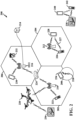
- the various concepts presented throughout this disclosure may be implemented across a broad variety of telecommunication systems, network architectures, and communication standards.
- the wireless communication system 100 includes three interacting domains: a core network 102, a radio access network (RAN) 104, and at least one scheduled entity 106.
- the at least one scheduled entity 106 may be referred to as a user equipment (UE) 106 in the discussion that follows.
- the RAN 104 includes at least one scheduling entity 108.
- the at least one scheduling entity 108 may be referred to as a base station (BS) 108 in the discussion that follows.
- the UE 106 may be enabled to carry out data communication with an external data network 110, such as (but not limited to) the Internet.
- an external data network 110 such as (but not limited to) the Internet.
- the RAN 104 may implement any suitable wireless communication technology or technologies to provide radio access to the UE 106.
- the RAN 104 may operate according to 3 rd Generation Partnership Project (3GPP) New Radio (NR) specifications, often referred to as 5G.
- 3GPP 3 rd Generation Partnership Project
- NR New Radio
- the RAN 104 may operate under a hybrid of 5G NR and Evolved Universal Terrestrial Radio Access Network (eUTRAN) standards, often referred to as LTE.
- eUTRAN Evolved Universal Terrestrial Radio Access Network
- the 3GPP refers to this hybrid RAN as a next-generation RAN, or NG-RAN.
- NG-RAN next-generation RAN
- a base station is a network element in a radio access network responsible for radio transmission and reception in one or more cells to or from a UE.
- a base station may variously be referred to by those skilled in the art as a base transceiver station (BTS), a radio base station, a radio transceiver, a transceiver function, a basic service set (BSS), an extended service set (ESS), an access point (AP), a Node B (NB), an eNode B (eNB), a gNode B (gNB), a transmission and reception point (TRP), or some other suitable terminology.
- a base station may include two or more TRPs that may be co-located or non-co-located. The TRPs may communicate on the same carrier frequency or different carrier frequencies within the same frequency band or different frequency bands.
- the radio access network 104 is further illustrated supporting wireless communication for multiple mobile apparatuses.
- a mobile apparatus may be referred to as user equipment (UE) in 3GPP standards, but may also be referred to by those skilled in the art as a mobile station (MS), a subscriber station, a mobile unit, a subscriber unit, a wireless unit, a remote unit, a mobile device, a wireless device, a wireless communications device, a remote device, a mobile subscriber station, an access terminal (AT), a mobile terminal, a wireless terminal, a remote terminal, a handset, a terminal, a user agent, a mobile client, a client, or some other suitable terminology.
- a UE may be an apparatus that provides a user with access to network services.
- a "mobile” apparatus need not necessarily have a capability to move, and may be stationary.
- the term mobile apparatus or mobile device broadly refers to a diverse array of devices and technologies.
- UEs may include a number of hardware structural components sized, shaped, and arranged to help in communication; such components can include antennas, antenna arrays, RF chains, amplifiers, one or more processors, etc. electrically coupled to each other.
- a mobile apparatus examples include a mobile, a cellular (cell) phone, a smart phone, a session initiation protocol (SIP) phone, a laptop, a personal computer (PC), a notebook, a netbook, a smartbook, a tablet, a personal digital assistant (PDA), and a broad array of embedded systems, e.g., corresponding to an "Internet of Things" (IoT).
- a cellular (cell) phone a smart phone, a session initiation protocol (SIP) phone
- laptop a personal computer
- PC personal computer
- notebook a netbook
- a smartbook a tablet
- PDA personal digital assistant
- IoT Internet of Things
- a mobile apparatus may additionally be an automotive or other transportation vehicle, a remote sensor or actuator, a robot or robotics device, a satellite radio, a global positioning system (GPS) device, an object tracking device, a drone, a multi-copter, a quad-copter, a remote control device, a consumer and/or wearable device, such as eyewear, a wearable camera, a virtual reality device, a smart watch, a health or fitness tracker, a digital audio player (e.g., MP3 player), a camera, a game console, etc.
- GPS global positioning system
- a mobile apparatus may additionally be a digital home or smart home device such as a home audio, video, and/or multimedia device, an appliance, a vending machine, intelligent lighting, a home security system, a smart meter, etc.
- a mobile apparatus may additionally be a smart energy device, a security device, a solar panel or solar array, a municipal infrastructure device controlling electric power (e.g., a smart grid), lighting, water, etc.; an industrial automation and enterprise device; a logistics controller; agricultural equipment; military defense equipment, vehicles, aircraft, ships, and weaponry, etc.
- a mobile apparatus may provide for connected medicine or telemedicine support, i.e., health care at a distance.
- Telehealth devices may include telehealth monitoring devices and telehealth administration devices, whose communication may be given preferential treatment or prioritized access over other types of information, e.g., in terms of prioritized access for transport of critical service data, and/or relevant QoS for transport of critical service data.
- Wireless communication between a RAN 104 and a UE 106 may be described as utilizing an air interface.
- Transmissions over the air interface from a base station (e.g., base station 108) to one or more UEs (e.g., UE 106) may be referred to as downlink (DL) transmission.
- the term downlink may refer to a point-to-multipoint transmission originating at a scheduling entity (described further below; e.g., base station 108). Another way to describe this point-to-multipoint transmission scheme may be to use the term broadcast channel multiplexing.
- Transmissions from a UE (e.g., UE 106) to a base station (e.g., base station 108) may be referred to as uplink (UL) transmissions.
- the term uplink may refer to a point-to-point transmission originating at a scheduled entity (described further below; e.g., UE 106).
- a scheduling entity e.g., a base station 108 allocates resources for communication among some or all devices and equipment within its service area or cell.
- the scheduling entity may be responsible for scheduling, assigning, reconfiguring, and releasing resources for one or more scheduled entities. That is, for scheduled communication, UEs 106, which may be scheduled entities, may utilize resources allocated by the scheduling entity 108.
- Base stations 108 are not the only entities that may function as scheduling entities. That is, in some examples, a UE may function as a scheduling entity, scheduling resources for one or more scheduled entities (e.g., one or more other UEs).
- a scheduling entity 108 may broadcast downlink traffic 112 to one or more scheduled entities 106.
- the scheduling entity 108 is a node or device responsible for scheduling traffic in a wireless communication network, including the downlink traffic 112 and, in some examples, uplink traffic 116 and/or uplink control information 118 from one or more scheduled entities 106 to the scheduling entity 108.
- the scheduled entity 106 is a node or device that receives downlink control information 114, including but not limited to scheduling information (e.g., a grant), synchronization or timing information, or other control information from another entity in the wireless communication network such as the scheduling entity 108.
- the uplink and/or downlink control information and/or traffic information may be time-divided into frames, subframes, slots, and/or symbols.
- a symbol may refer to a unit of time that, in an orthogonal frequency division multiplexed (OFDM) waveform, carries one resource element (RE) per sub-carrier.
- a slot may carry 7 or 14 OFDM symbols in some examples.
- a subframe may refer to a duration of 1 millisecond (ms). Multiple subframes or slots may be grouped together to form a single frame or radio frame.
- OFDM orthogonal frequency division multiplexed
- ms millisecond
- Multiple subframes or slots may be grouped together to form a single frame or radio frame.
- base stations 108 may include a backhaul interface for communication with a backhaul portion 120 of the wireless communication system.
- the backhaul 120 may provide a link between a base station 108 and the core network 102.
- a backhaul network may provide interconnection between the respective base stations 108.
- Various types of backhaul interfaces may be employed, such as a direct physical connection, a virtual network, or the like using any suitable transport network.
- the core network 102 may be a part of the wireless communication system 100, and may be independent of the radio access technology used in the RAN 104.
- the core network 102 may be configured according to 5G standards (e.g., 5GC).
- the core network 102 may be configured according to a 4G evolved packet core (EPC), or any other suitable standard or configuration.
- 5G standards e.g., 5GC
- EPC 4G evolved packet core
- FIG. 2 by way of example and without limitation, a schematic illustration of a RAN 200 is provided.
- the RAN 200 may be the same as the RAN 104 described above and illustrated in FIG. 1 .
- the geographic area covered by the RAN 200 may be divided into cellular regions (cells) that can be uniquely identified by a user equipment (UE) based on an identification broadcasted from one access point or base station.
- FIG. 2 illustrates macrocells 202, 204, and 206, and a small cell 208, each of which may include one or more sectors (not shown).
- a sector is a sub-area of a cell. All sectors within one cell are served by the same base station.
- a radio link within a sector can be identified by a single logical identification belonging to that sector.
- the multiple sectors within a cell can be formed by groups of antennas with each antenna responsible for communication with UEs in a portion of the cell.
- FIG. 2 two base stations 210 and 212 are shown in cells 202 and 204; and a third base station 214 is shown controlling a remote radio head (RRH) 216 in cell 206. That is, a base station can have an integrated antenna or can be connected to an antenna or RRH by feeder cables.
- a base station can have an integrated antenna or can be connected to an antenna or RRH by feeder cables.
- the cells 202, 204, and 206 may be referred to as macrocells, as the base stations 210, 212, and 214 support cells having a large size.
- a base station 218 is shown in the small cell 208 (e.g., a microcell, picocell, femtocell, home base station, home Node B, home eNode B, etc.) which may overlap with one or more macrocells.
- the cell 208 may be referred to as a small cell, as the base station 218 supports a cell having a relatively small size. Cell sizing can be done according to system design as well as component constraints.
- the radio access network 200 may include any number of wireless base stations and cells. Further, a relay node may be deployed to extend the size or coverage area of a given cell.
- the base stations 210, 212, 214, 218 provide wireless access points to a core network for any number of mobile apparatuses. In some examples, the base stations 210, 212, 214, and/or 218 may be the same as the base station/scheduling entity 108 described above and illustrated in FIG. 1 .
- the cells may include UEs that may be in communication with one or more sectors of each cell.
- each base station 210, 212, 214, and 218 may be configured to provide an access point to a core network (e.g., as illustrated in FIG. 1 ) for all the UEs in the respective cells.
- UEs 222 and 224 may be in communication with base station 210; UEs 226 and 228 may be in communication with base station 212; UEs 230 and 232 may be in communication with base station 214 by way of RRH 216; and UE 234 may be in communication with base station 218.
- the UEs 222, 224, 226, 228, 230, 232, 234, 236, 238, 240, and/or 242 may be the same as the UE/scheduled entity 106 described above and illustrated in FIG. 1 .
- an unmanned aerial vehicle (UAV) 220 which may be a drone or quadcopter, can be a mobile network node and may be configured to function as a UE.
- the UAV 220 may operate within cell 202 by communicating with base station 210.
- a UAV 220 may be configured to function as a BS (e.g., serving a UE 236). That is, in some examples, a cell may not necessarily be stationary, and the geographic area of the cell may move according to the location of a mobile base station such as a UAV 220.
- the network 200 may handover the UE 224 from the serving cell to the neighboring cell, with or without informing the UE 224.
- the synchronization signal transmitted by the base stations 210, 212, and 214/216 may be unified, the synchronization signal may not identify a particular cell, but rather may identify a zone of multiple cells operating on the same frequency and/or with the same timing.
- the use of zones in 5G networks or other next generation communication networks enables the uplink-based mobility framework and improves the efficiency of both the UE and the network, since the number of mobility messages that need to be exchanged between the UE and the network may be reduced.
- multiplexing and multiple access are not limited to the above schemes, and may be provided utilizing time division multiple access (TDMA), code division multiple access (CDMA), frequency division multiple access (FDMA), sparse code multiple access (SCMA), resource spread multiple access (RSMA), or other suitable multiple access schemes.
- multiplexing DL transmissions from the base station 210 to UEs 222 and 224 may be provided utilizing time division multiplexing (TDM), code division multiplexing (CDM), frequency division multiplexing (FDM), orthogonal frequency division multiplexing (OFDM), sparse code multiplexing (SCM), or other suitable multiplexing schemes.
- two or more UEs within the coverage area of a serving base station 212 may communicate with both the base station 212 using cellular signals and with each other using direct link signals (e.g., sidelink signals 227) without relaying that communication through the base station.
- the base station 212 and/or one or both of the UEs 226 and 228 may function as scheduling entities to schedule sidelink communication between UEs 226 and 228.
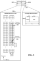
- the resource grid 304 may be used to schematically represent time-frequency resources for a given antenna port. That is, in a multiple-input-multiple-output (MIMO) implementation with multiple antenna ports available, a corresponding multiple number of resource grids 304 may be available for communication.
- the resource grid 304 is divided into multiple resource elements (REs) 306.
- An RE which is 1 subcarrier ⁇ 1 symbol, is the smallest discrete part of the time-frequency grid, and contains a single complex value representing data from a physical channel or signal.
- each RE may represent one or more bits of information.
- a block of REs may be referred to as a physical resource block (PRB) or more simply a resource block (RB) 308, which contains any suitable number of consecutive subcarriers in the frequency domain.
- PRB physical resource block
- RB resource block
- an RB may include 12 subcarriers, a number independent of the numerology used.
- an RB may include any suitable number of consecutive OFDM symbols in the time domain.
- Scheduling of UEs typically involves scheduling one or more resource elements 306 within one or more sub-bands or bandwidth parts (BWPs).
- BWP bandwidth parts
- Each BWP may include two or more contiguous or consecutive RBs.
- a UE generally utilizes only a subset of the resource grid 304.
- an RB may be the smallest unit of resources that can be allocated to a UE.
- the RBs may be scheduled by a base station (e.g., gNB, eNB, RSU, etc.) or may be self-scheduled by a UE implementing D2D sidelink communication.
- the RB 308 is shown as occupying less than the entire bandwidth of the subframe 302A, with some subcarriers illustrated above and below the RB 308.
- the subframe 302A may have a bandwidth corresponding to any number of one or more RBs 308.
- the RB 308 is shown as occupying less than the entire duration of the subframe 302A, although this is merely one possible example.
- Each 1 ms subframe 302A may consist of one or multiple adjacent slots.
- one subframe 302B includes four slots 310, as an illustrative example.
- a slot may be defined according to a specified number of OFDM symbols with a given cyclic prefix (CP) length.
- CP cyclic prefix
- a slot may include 7 or 14 OFDM symbols with a nominal CP.
- Additional examples may include mini-slots having a shorter duration (e.g., one or two OFDM symbols). These mini-slots may in some cases be transmitted occupying resources scheduled for ongoing slot transmissions for the same or for different UEs. Any number of resource blocks may be utilized within a subframe or slot.
- An expanded view of one of the slots 310 illustrates the slot 310 including a control region 312 and a data region 314.
- the control region 312 may carry control channels (e.g., PDCCH)
- the data region 314 may carry data channels (e.g., PDSCH or PUSCH).
- a slot may contain all DL, all UL, or at least one DL portion and at least one UL portion.
- the structure illustrated in FIG. 3 is merely an example, and different slot structures may be utilized, and may include one or more of each of the control region(s) and data region(s).
- the various REs 306 within a RB 308 may be scheduled to carry one or more physical channels, including control channels, shared channels, data channels, etc.
- Other REs 306 within the RB 308 may also carry pilots or reference signals, including but not limited to a demodulation reference signal (DMRS), a control reference signal (CRS), or a sounding reference signal (SRS). These pilots or reference signals may provide for a receiving device to perform channel estimation of the corresponding channel, which may enable coherent demodulation/detection of the control and/or data channels within the RB 308.
- DMRS demodulation reference signal
- CRS control reference signal
- SRS sounding reference signal
- a slot 310 may be utilized for broadcast or unicast communication.
- a broadcast communication may refer to a point-to-multipoint transmission by a one device (e.g., a vehicle, base station (e.g., RSU, gNB, eNB, etc.), UE, or other similar device) to other devices.
- a unicast communication may refer to a point-to-point transmission by a one device to a single other device.
- the control region 312 of the slot 310 may include a physical downlink control channel (PDCCH) including downlink control information (DCI) transmitted by a base station (e.g., gNB, eNB, RSU, etc.) towards one or more of a set of UEs, which may include one or more sidelink devices (e.g., V2X/D2D devices).
- DCI downlink control information
- the DCI may include synchronization information to synchronize communication by a plurality of sidelink devices on the sidelink channel.
- the DCI may include scheduling information indicating one or more resource blocks within the control region 312 and/or data region 314 allocated to sidelink devices for sidelink communication.
- the SSB may be used to send system information (SI) and/or provide a reference to SI transmitted via another channel.
- system information may include, but are not limited to, subcarrier spacing, system frame number, a cell global identifier (CGI), a cell bar indication, a list of common control resource sets (coresets), a list of common search spaces, a search space for system information block 1 (SIB 1), a paging search space, a random access search space, and uplink configuration information.
- coresets include PDCCH CORESET 0 and CORESET 1.
- the PDCCH may carry downlink control information (DCI) including but not limited to power control commands, scheduling information, a grant, and/or an assignment of REs for DL and UL transmissions.
- DCI downlink control information
- the PHY carries HARQ feedback transmissions such as an acknowledgment (ACK) or negative acknowledgment (NACK).
- HARQ is a technique well-known to those of ordinary skill in the art, wherein the integrity of packet transmissions may be checked at the receiving side for accuracy, e.g., utilizing any suitable integrity checking mechanism, such as a checksum or a cyclic redundancy check (CRC). If the integrity of the transmission is confirmed, an ACK may be transmitted, whereas if not confirmed, a NACK may be transmitted. In response to a NACK, the transmitting device may send a HARQ retransmission, which may implement chase combining, incremental redundancy, etc.
- CRC cyclic redundancy check
- the transmitting device may utilize one or more REs 306 to carry UL control information including one or more UL control channels, such as a physical uplink control channel (PUCCH), to the scheduling entity.
- UL control information may include a variety of packet types and categories, including pilots, reference signals, and information configured to enable or assist in decoding uplink data transmissions.
- the UL control information may include a DMRS or SRS.
- the control information may include a scheduling request (SR), i.e., a request for the scheduling entity to schedule uplink transmissions.
- SR scheduling request
- the scheduling entity may transmit downlink control information that may schedule resources for uplink packet transmissions.
- UL control information may also include HARQ feedback, channel state feedback (CSF), or any other suitable UL control information.
- channels or carriers described above with reference to FIGs. 1 - 3 are not necessarily all of the channels or carriers that may be utilized between a scheduling entity and scheduled entities, and those of ordinary skill in the art will recognize that other channels or carriers may be utilized in addition to those illustrated, such as other traffic, control, and feedback channels.
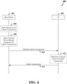
- FIG. 4 is a signaling diagram 400 illustrating an example of resource scheduling for an uplink transmission in a wireless communication system including a base station (BS) 402 and a UE 404.
- the BS 402 may correspond to any of the base stations or scheduling entities shown in any of FIGs. 1 , 2 , 5 , and 6 .
- the UE 404 may correspond to any of the UEs or scheduled entities shown in any of FIGs. 1 , 2 , 5 , 6 , and 10 .
- the BS 402 selects resources for an uplink transmission. For example, the BS 402 may allocate resources to be used by the UE 404 for a PUSCH transmission, for a PUCCH transmission, or for an SRS transmission.
- the BS 402 selects transmit power-related parameters for the uplink transmission. For example, the BS 402 may select one or more parameters that the UE 404 uses to calculate a PUSCH transmission power in a PUSCH transmission occasion, a PUCCH transmission power in a PUCCH transmission occasion, or an SRS transmission power in an SRS transmission occasion.
- the BS 402 schedules the uplink transmission. For example, the BS 402 may send a DCI to the UE 404 on a PDCCH, where the DCI specifies the resources and other information to be used by the UE 404 for the uplink transmission.
- the UE 404 determines the transmit power to be used for the uplink transmission. In some aspects, this determination may be based on information the BS 402 provided to the UE 404 (e.g., the information from step 408).
- the UE 404 transmits the uplink transmission on the scheduled resources.
- the UE 404 may transmit a PUSCH transmission, a PUCCH transmission, or an SRS transmission.
- An SRS transmission may involve a UE transmitting SRSs that a base station may use for various purposes including, for example, channel estimation, positioning, codebook generation, and beam selection.
- a UE may transmit SRSs to a base station over a specified bandwidth to enable the base station to estimate the uplink channel over that bandwidth.
- the base station may better schedule uplink transmissions from the UE (e.g., the base station may select the frequency band and transmission parameters the UE is to use for an uplink transmission).
- a base station may transmit SRS configuration information to a UE that specifies the SRS resources and other parameters to be used by a UE to transmit SRSs. For example, a base station may configure one or more SRS resource sets for a UE. In some examples, a UE may use different resource sets for transmitting on different symbols. A defined number of antenna ports may be used for each SRS resource. In some examples, a given antenna port may correspond to a particular set of antenna elements and/or other beamforming parameters (e.g., signal phases and/or amplitudes).
- a base station may communicate with a UE using multiple antennas. For example, a base station may transmit parallel data streams over respective antennas to increase throughput (e.g., as opposed to transmitting the data streams sequentially over the same antenna). Additionally, or alternatively, a base station may simultaneously transmit a given data stream over multiple antennas (e.g., to increase the diversity of the transmissions).
- 5G-NR networks may support carrier aggregation (CA) of component carriers transmitted from different cells and/or different transmission and reception points (TRPs) in a multi-cell transmission environment.
- CA carrier aggregation
- the different TRPs may be associated with a single serving cell or multiple serving cells.
- the term component carrier may refer to a carrier frequency (or band) utilized for communication within a cell.
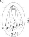
- FIG. 5 is a conceptual illustration of a wireless communication system that shows a base station (BS) and a user equipment (UE) communicating via multiple carriers according to some aspects of the disclosure.
- FIG. 5 shows an example of a wireless communication system 500 that includes a primary serving cell (PCell) 502 and one or more secondary serving cells (SCells) 506a, 506b, and 506c.
- the PCell 502 may be referred to as the anchor cell that provides a radio resource control (RRC) connection to a UE 510.
- RRC radio resource control
- the PCell and the SCell may be co-located (e.g., different TRPs at the same location).
- One or more of the SCells 506a - 506c may be activated or added to the PCell 502 to form the serving cells serving the UE 510.
- Each serving cell corresponds to a component carrier (CC).
- the CC of the PCell 502 may be referred to as a primary CC, and the CC of an SCell 506a - 506c may be referred to as a secondary CC.
- the PCell 502 and one or more of the SCells 506 may be served by a respective base station 504 and 508a - 508c or scheduling entity similar to those illustrated in any of FIGs. 1 , 2 , 4 , and 6 .
- SCells 506a - 506c are each served by a respective base station 508a - 508c or TRPs of the base station 504, each supporting a different carrier.
- the PCell 502 may utilize a first radio access technology (RAT), such as LTE, while one or more of the SCells 506 may utilize a second RAT, such as 5G-NR.
- RAT radio access technology
- the multi-cell transmission environment may be referred to as a multi-RAT - dual connectivity (MR-DC) environment.
- MR-DC multi-RAT - dual connectivity
- Evolved-Universal Terrestrial Radio Access Network - New Radio dual connectivity (EN-DC) mode that enables a UE to simultaneously connect to an LTE base station and a NR base station to receive data packets from and send data packets to both the LTE base station and the NR base station.
- the PCell 502 may be a low band cell
- the SCells 506 may be high band cells.
- a low band (LB) cell uses a component carrier in a frequency band lower than that of the high band cells.
- the high band cells may use millimeter wave (mmW) component carriers
- the low band cell may use a component carrier in a band (e.g., sub-6GHz band) lower than mmW.
- mmW millimeter wave
- a cell using a mmW component carrier can provide greater bandwidth than a cell using a low band component carrier.
- beamforming may be used to transmit and receive signals in some examples.
- An antenna port is a logical entity used to map data streams to antennas.
- a given antenna port may drive transmissions from one or more antennas (e.g., and resolve signal components received over one or more antennas).
- Each antenna port may be associated with a reference signal (e.g., which may allow the receiver to distinguish data streams associated with the different antenna ports in a received transmission).
- Some antenna ports may be referred to as being quasi co-located, meaning that the spatial parameters of a transmission on one antenna port may be inferred from the spatial parameters of another transmission on a different antenna port.
- a receiving device e.g., a UE
- a quasi co-location (QCL) relationship between antenna ports may improve the chances that a UE may successfully decode a downlink transmission from a base station.
- a base station may transmit to a UE an indication of which antenna ports are quasi co-located such that the UE may be able to identify additional reference signals to use for channel estimation.
- the TCI-state ID When a TCI-state ID is activated for a CORESET by a MAC CE for a set of CCsBWPs at least for the same band, where the applicable list of component carriers is indicated by RRC signaling, the TCI-state ID may be applied for the CORESET(s) with the same CORESET ID for all the BWPs in the indicated component carriers.
- the Spatial Relation Info When a Spatial Relation Info is activated for a SP/AP SRS resource by a MAC CE for a set of CCsBWPs at least for the same band, where the applicable list of component carriers is indicated by RRC signaling, the Spatial Relation Info may be applied for the SP/AP SRS resource(s) with the same SRS resource ID for all the BWPs in the indicated component carriers.
- inter-band CA for this feature may be supported.
- a device may indicate the applicable list of bands for the feature of a single MAC-CE activating the same set of PDSCH TCI state IDs for multiple CCs/BWPs. In some aspects, this may at least apply to the single TRP case. Different combinations of component carriers can be configured by RRC signaling and different UE capabilities may be supported.
- the BS 602 sends an indication of a set of pathloss reference signal identifiers (IDs) to the UE 604.
- the BS 602 may an RRC message that includes a list of pathloss reference signal identifiers (IDs) associated with pathloss RSs used by the BS 602.
- the BS 602 sends a MAC-CE to the UE 604.
- the MAC-CE includes an indication to activate and/or update a pathloss RS ID.
- the MAC-CE may include an identifier of a particular pathloss RS to be used by the UE for calculating transmit power for an uplink transmission.
- the MAC-CE may include an identifier of a particular component carrier (e.g., the component carrier for which the MAC-CE applies).
- the BS 602 may use the MAC-CE to activate/update a pathloss RS ID at a faster rate than may be achieved using RRC signaling to activate update a pathloss RS ID.
- the BS 602 schedules a PUSCH, PUCCH, or SRS transmission by the UE 604.
- the BS 602 may send a DCI to the UE 604 that schedules the transmission.
- FIG. 7 is a flow chart illustrating an example process 700 for a wireless communication system in accordance with some aspects of the present disclosure. As described below, some or all illustrated features may be omitted in a particular implementation within the scope of the present disclosure, and some illustrated features may not be required for implementation of all embodiments.
- the process 700 may be carried out by the UE 1000 illustrated in FIG. 10 . In some examples, the process 700 may be carried out by any suitable apparatus or means for carrying out the functions or algorithm described below.
- the UE applies the pathloss reference signal identifier to all component carriers (and associated BWPs ) of the set for the PUSCH transmission.
- this approach may advantageously save overhead and latency for PUSCH transmissions since a single MAC-CE (as opposed to multiple messages) may activate and/or update multiple component carriers.
- the operations of block 706 may correspond to the operations of steps 616 - 622 of FIG. 6 .
- the UE applies the pathloss reference signal identifier to all component carriers (and associated BWPs ) of the set for the PUCCH transmission.
- this approach may advantageously save overhead and latency for PUCCH transmissions since a single MAC-CE (as opposed to multiple messages) may activate and/or update multiple component carriers.
- the operations of block 806 may correspond to the operations of steps 616 - 622 of FIG. 6 .
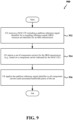
- FIG. 9 is a flow chart illustrating an example process 900 for a wireless communication system in accordance with some aspects of the present disclosure. As described below, some or all illustrated features may be omitted in a particular implementation within the scope of the present disclosure, and some illustrated features may not be required for implementation of all embodiments.
- the process 900 may be carried out by the UE 1000 illustrated in FIG. 10 . In some examples, the process 900 may be carried out by any suitable apparatus or means for carrying out the functions or algorithm described below.
- a UE receives a MAC-CE including a pathloss reference signal identifier for an SRS resource set for an SRS transmission.
- the operations of block 902 may correspond to the operations of step 610 of FIG. 6 .
- the UE selects a set of component carriers for the SRS transmission.
- this operation may involve identifying the set of component carriers (e.g., from a previously configured plurality of sets of component carriers) that contains a component carrier indicated by the MAC-CE.
- the component carrier indicated by the MAC-CE is the serving cell for which the MAC-CE applies.
- the operations of block 904 may correspond to the operations of step 612 of FIG. 6 .
- the UE applies the pathloss reference signal identifier to all component carriers (and associated BWPs ) of the set for the SRS transmission.
- this approach may advantageously save overhead and latency for SRS transmissions since a single MAC-CE (as opposed to multiple messages) may activate and/or update multiple component carriers.
- the operations of block 906 may correspond to the operations of steps 616 - 622 of FIG. 6 .
- FIG. 10 is a block diagram illustrating an example of a hardware implementation for a UE 1000 employing a processing system 1014.
- the UE 1000 may be a device configured to wirelessly communicate with a base station, as discussed in any one or more of FIGs. 1 - 9 .
- the UE 1000 may correspond to any of the UEs or scheduled entities shown in any of FIGs. 1 , 2 , 4 , 5 , and 6 .
- the processing system 1014 may include one or more processors 1004.
- processors 1004 include microprocessors, microcontrollers, digital signal processors (DSPs), field programmable gate arrays (FPGAs), programmable logic devices (PLDs), state machines, gated logic, discrete hardware circuits, and other suitable hardware configured to perform the various functionality described throughout this disclosure.
- DSPs digital signal processors
- FPGAs field programmable gate arrays
- PLDs programmable logic devices
- state machines gated logic, discrete hardware circuits, and other suitable hardware configured to perform the various functionality described throughout this disclosure.
- the UE 1000 may be configured to perform any one or more of the functions described herein. That is, the processor 1004, as utilized in a UE 1000, may be used to implement any one or more of the processes and procedures described herein.
- the processor 1004 may in some instances be implemented via a baseband or modem chip and in other implementations, the processor 1004 may include a number of devices distinct and different from a baseband or modem chip (e.g., in such scenarios as may work in concert to achieve embodiments discussed herein). And as mentioned above, various hardware arrangements and components outside of a baseband modem processor can be used in implementations, including RF-chains, power amplifiers, modulators, buffers, interleavers, adders/summers, etc.
- the processing system 1014 may be implemented with a bus architecture, represented generally by the bus 1002.
- the bus 1002 may include any number of interconnecting buses and bridges depending on the specific application of the processing system 1014 and the overall design constraints.
- the bus 1002 communicatively couples together various circuits including one or more processors (represented generally by the processor 1004), a memory 1005, and computer-readable media (represented generally by the computer-readable medium 1006).
- the bus 1002 may also link various other circuits such as timing sources, peripherals, voltage regulators, and power management circuits, which are well known in the art, and therefore, will not be described any further.
- a bus interface 1008 provides an interface between the bus 1002 and a transceiver 1010 and between the bus 1002 and an interface 1030.
- the transceiver 1010 provides a communication interface or means for communicating with various other apparatus over a wireless transmission medium.
- the UE may include two or more transceivers 1010, each configured to communicate with a respective network type (e.g., terrestrial or non-terrestrial).
- the interface 1030 provides a communication interface or means of communicating with various other apparatuses and devices (e.g., other devices housed within the same apparatus as the UE or other external apparatuses) over an internal bus or external transmission medium, such as an Ethernet cable.
- the interface 1030 may include a user interface (e.g., keypad, display, speaker, microphone, joystick). Of course, such a user interface is optional, and may be omitted in some examples, such as an IoT device.
- the processor 1004 is responsible for managing the bus 1002 and general processing, including the execution of software stored on the computer-readable medium 1006.
- the software when executed by the processor 1004, causes the processing system 1014 to perform the various functions described below for any particular apparatus.
- the computer-readable medium 1006 and the memory 1005 may also be used for storing data that is manipulated by the processor 1004 when executing software.
- the memory 1005 may store power control information (e.g., parameters for a power control algorithm) used by the processor 1004 to control the transmit power of the UE 1000.
- One or more processors 1004 in the processing system may execute software.
- Software shall be construed broadly to mean instructions, instruction sets, code, code segments, program code, programs, subprograms, software modules, applications, software applications, software packages, routines, subroutines, objects, executables, threads of execution, procedures, functions, etc., whether referred to as software, firmware, middleware, microcode, hardware description language, or otherwise.
- the software may reside on a computer-readable medium 1006.
- the computer-readable medium 1006 may be a non-transitory computer-readable medium.
- a non-transitory computer-readable medium includes, by way of example, a magnetic storage device (e.g., hard disk, floppy disk, magnetic strip), an optical disk (e.g., a compact disc (CD) or a digital versatile disc (DVD)), a smart card, a flash memory device (e.g., a card, a stick, or a key drive), a random access memory (RAM), a read only memory (ROM), a programmable ROM (PROM), an erasable PROM (EPROM), an electrically erasable PROM (EEPROM), a register, a removable disk, and any other suitable medium for storing software and/or instructions that may be accessed and read by a computer.
- a magnetic storage device e.g., hard disk, floppy disk, magnetic strip
- an optical disk e.g., a compact disc (CD) or a digital versatile disc (DVD
- the computer-readable medium 1006 may reside in the processing system 1014, external to the processing system 1014, or distributed across multiple entities including the processing system 1014.
- the computer-readable medium 1006 may be embodied in a computer program product.
- a computer program product may include a computer-readable medium in packaging materials.
- the UE 1000 may be configured to perform any one or more of the operations described herein (e.g., as described above in conjunction with FIGs. 1 - 9 and as described below in conjunction with FIGs. 11 - 16 ).
- the processor 1004 as utilized in the UE 1000, may include circuitry configured for various functions.
- the processor 1004 may include communication and processing circuitry 1041.
- the communication and processing circuitry 1041 may be configured to communicate with a base station, such as a gNB.
- the communication and processing circuitry 1041 may include one or more hardware components that provide the physical structure that performs various processes related to wireless communication (e.g., signal reception and/or signal transmission) as described herein.
- the communication and processing circuitry 1041 may further include one or more hardware components that provide the physical structure that performs various processes related to signal processing (e.g., processing a received signal and/or processing a signal for transmission) as described herein.
- the communication and processing circuitry 1041 may include two or more transmit/receive chains, each configured to process signals in a different RAT (or RAN) type.
- the communication and processing circuitry 1041 may further be configured to execute communication and processing software 1051 included on the computer-readable medium 1006 to implement one or more functions described herein.
- the communication and processing circuitry 1041 may be configured to receive and process downlink beamformed signals at a mmWave frequency or a sub-6 GHz frequency via the transceiver 1010 and an antenna array 1020.
- the communication and processing circuitry 1041 may be configured to receive a respective reference signal (e.g., SSB or CSI-RS) on each of a plurality of downlink beams from the base station during a downlink beam sweep via at least one first antenna panel of the antenna array 1020.
- the communication and processing circuitry 1041 may further be configured to transmit a beam measurement report to the base station.
- the communication and processing circuitry 1041 may further be configured to generate and transmit uplink beamformed signals at a mmWave frequency or a sub-6 GHz frequency via the transceiver 1010 and the antenna array 1020.
- the communication and processing circuitry 1041 may be configured to transmit a respective reference signal (e.g., SRS or DMRS) on each of a plurality of uplink beams to the base station during an uplink beam sweep via at least one second antenna panel of the antenna array 1020.
- a respective reference signal e.g., SRS or DMRS
- the communication and processing circuitry 1041 may further be configured to generate and transmit a request to the base station.
- the request may be included in a MAC-CE carried in a PUSCH, UCI in a PUCCH or PUSCH, a random access message, or an RRC message.
- the communication and processing circuitry 1041 may further be configured to generate and transmit a scheduling request (e.g., via UCI in a PUCCH) to the base station to receive an uplink grant for a PUSCH.
- the communication and processing circuitry 1041 may further be configured to generate and transmit an uplink signal on one or more uplink transmit beams applied to the uplink signal.
- the uplink signal may include, for example, a PUCCH, PUSCH, SRS, DMRS, or PRACH.
- the communication and processing circuitry 1041 may further be configured to control the antenna array 1020 and the transceiver 1010 to search for and identify a plurality of downlink transmit beams during a downlink beam sweep.
- the communication and processing circuitry 1041 may further be configured to obtain a plurality of beam measurements on each of a plurality of downlink receive beams via the antenna array 1020 for each of the identified downlink transmit beams.
- the communication and processing circuitry 1041 may further be configured to generate a beam measurement report for transmission to the base station using the transceiver 1010.
- the communication and processing circuitry 1041 may further be configured to identify one or more selected uplink beam(s) based on the beam measurements obtained from the downlink beam reference signals.
- the communication and processing circuitry 1041 may be configured to compare the respective reference signal received power (RSRP) or other beam measurement measured on each of the downlink receive beams for each of the serving downlink transmit beams to identify the serving downlink receive beams and to further utilize the serving downlink receive beams as the selected uplink transmit beams.
- RSRP reference signal received power
- Each serving downlink receive beam may have the highest measured RSRP (or other beam measurement) for one of the downlink transmit beams.
- the communication and processing circuitry 1041 may be configured to generate one or more uplink transmit beams for transmission in an uplink beam sweep. Each uplink transmit beam may carry an uplink reference signal (e.g., an SRS) for measurement by the base station.
- the communication and processing circuitry 1041 may further be configured to identify the selected uplink transmit beam(s) selected by the base station based on the uplink beam measurements. For example, the communication and processing circuitry 1041 may be configured to receive an indication of the selected uplink transmit beam(s) from the base station.
- the communication and processing circuitry 1041 may obtain information from a component of the UE 1000 (e.g., from the transceiver 1010 that receives the information via radio frequency signaling or some other type of signaling suitable for the applicable communication medium), process (e.g., decode) the information, and output the processed information.
- the communication and processing circuitry 1041 may output the information to another component of the processor 1004, to the memory 1005, or to the bus interface 1008.
- the communication and processing circuitry 1041 may receive one or more of signals, messages, other information, or any combination thereof.
- the communication and processing circuitry 1041 may receive information via one or more channels.
- the communication and processing circuitry 1041 may include functionality for a means for receiving.
- the communication and processing circuitry 1041 may include functionality for a means for decoding.
- the communication and processing circuitry 1041 may obtain information (e.g., from another component of the processor 1004, the memory 1005, or the bus interface 1008), process (e.g., encode) the information, and output the processed information.
- the communication and processing circuitry 1041 may output the information to the transceiver 1010 (e.g., that transmits the information via radio frequency signaling or some other type of signaling suitable for the applicable communication medium).
- the communication and processing circuitry 1041 may send one or more of signals, messages, other information, or any combination thereof.
- the communication and processing circuitry 1041 may send information via one or more channels.
- the communication and processing circuitry 1041 may include functionality for a means for sending (e.g., a means for transmitting).
- the communication and processing circuitry 1041 may include functionality for a means for encoding.
- the processor 1004 may include power control configuration circuitry 1042 configured to perform power control configuration-related operations as discussed herein (e.g., one or more of the operations described in conjunction with FIGs. 6 - 9 ).
- the power control configuration circuitry 1042 may include functionality for a means for receiving (e.g., as described at step 606, 608, 610, 614, and/or 616 of FIG. 6 and/or block 1102 of FIG. 11 and/or block 1402 of FIG. 14 and/or block 1502 of FIG. 15 and/or block 1602 of FIG. 16 ).
- the power control configuration circuitry 1042 may include functionality for a means for identifying component carriers (e.g., as described at step 612 of FIG. 6 and/or block 1104 of FIG.
- the power control configuration circuitry 1042 may further be configured to execute power control configuration software 1052 included on the computer-readable medium 1006 to implement one or more functions described herein.
- the power control configuration circuitry 1042 may be configured to receive lists of component carriers from a base station (e.g., via RRC signaling, MAC-CE signaling, or other signaling). For example, the power control configuration circuitry 1042 in cooperation with the transceiver 1010 may monitor for signals on downlink resources scheduled by a gNB, and decode the signals to determine whether the gNB transmitted information to the UE 1000 via a particular channel (e.g., a PDSCH). In some examples, the power control configuration circuitry 1042 may be configured to receive configuration information such as pathloss reference signal information from a base station (e.g., via RRC signaling, MAC-CE signaling, or other signaling).
- configuration information such as pathloss reference signal information from a base station (e.g., via RRC signaling, MAC-CE signaling, or other signaling).
- the power control configuration circuitry 1042 may be configured to receive information that identifies one or more of the component carriers of the lists of component carriers. For example, the power control configuration circuitry 1042 may receive a MAC-CE that identifies a particular component carrier. As another example, the MAC-CE may indicate an update and/or modification of the list of component carriers indicated by RRC signaling. In some examples, the power control configuration circuitry 1042 may be configured to apply the pathloss reference signal information to a set of component carriers. For example, a determination of a particular set of component carriers may be based on a component carrier indicated by a MAC-CE. In some examples, the power control configuration circuitry 1042 may determine which set of a plurality of sets of component carriers includes the component carrier indicated by the MAC-CE.
- the processor 1004 may include power control processing circuitry 1043 configured to perform power control processing-related operations as discussed herein (e.g., one or more of the operations described in conjunction with FIGs. 6 - 9 ).
- the power control processing circuitry 1043 may include functionality for a means for applying pathloss reference signal information (e.g., as described at step 618 and/or 620 of FIG. 6 and/or block 1106 of FIG. 11 and/or block 1406 of FIG. 14 and/or block 1506 of FIG. 15 and/or block 1606 of FIG. 16 ).
- the power control processing circuitry 1043 may include functionality for a means for transmitting (e.g., as described at step 622 of FIG. 6 and/or block 1108 of FIG. 11 and/or block 1408 of FIG. 14 and/or block 1508 of FIG. 15 and/or block 1608 of FIG. 16 ).
- the power control processing circuitry 1043 may further be configured to execute power control processing software 1053 included on the computer-readable medium 1006 to implement one or more functions
- the power control processing circuitry 1043 may be configured to calculate a transmit power for a PUSCH transmission during a PUSCH transmission occasion, a PUCCH transmission during a PUCCH transmission occasion, or an SRS transmission during an SRS transmission occasion. In some examples, calculating the transmit power may involve determining a pathloss parameter for a transmit power equation. In some examples, the power control processing circuitry 1043 may be configured to determine the pathloss parameter by measuring reference signals transmitted by a base station and comparing the received power (e.g., RSRP) with the transmit power used by the base station to transmit the reference signals. Here, the reference signals to be measured by the power control processing circuitry 1043 may be indicated by the pathloss reference signal identifier.
- RSRP received power
- the base station may send to the UE an indication of the transmit power used by the base station to transmit the reference signals.
- the power control processing circuitry 1043 may calculate the transmit power for uplink transmissions on a set of component carriers (e.g., the set of component carriers that includes the component carrier indicated by the MAC-CE). The power control processing circuitry 1043 may then cooperate with the transceiver 1010 to configure the transmit power to be used for transmissions on the set of component carriers.
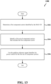
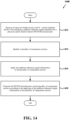
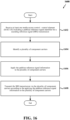
- FIG. 11 is a flow chart illustrating an example process 1100 for a wireless communication system in accordance with some aspects of the present disclosure. As described below, some or all illustrated features may be omitted in a particular implementation within the scope of the present disclosure, and some illustrated features may not be required for implementation of all embodiments.
- the process 1100 may be carried out by the UE 1000 illustrated in FIG. 10 . In some examples, the process 1100 may be carried out by any suitable apparatus or means for carrying out the functions or algorithm described below.
- a UE may receive at least one medium access control - control element (MAC-CE) that includes pathloss reference signal information.
- MAC-CE medium access control - control element
- the power control configuration circuitry 1042 together with the communication and processing circuitry 1041 and the transceiver 1010, shown and described above in connection with FIG. 10 , may monitor a designated PDSCH and decode signals received on that channel to determine whether a gNB has transmitted a MAC-CE to the UE.
- the power control configuration circuitry 1042 may then parse the MAC-CE to determine whether the MAC-CE is activating and/or updating a pathloss RS ID.
- the pathloss reference signal information may include a pathloss reference signal identifier for a physical uplink shared channel (PUSCH) transmission.
- the pathloss reference signal identifier corresponds to a sounding reference signal (SRS) resource indicator (SRI) PUSCH power control identifier for the PUSCH transmission.
- SRS sounding reference signal
- SRI resource indicator
- the pathloss reference signal information may include a pathloss reference signal identifier for a physical uplink control channel (PUCCH) transmission.
- PUCCH physical uplink control channel
- the pathloss reference signal information may include a pathloss reference signal identifier for a sounding reference signal (SRS) transmission.
- the pathloss reference signal identifier is for an SRS resource set for the SRS transmission.
- the UE may identify a plurality of component carriers. For example, the power control configuration circuitry 1042 may determine whether the UE has been configured with a list of component carriers. In some examples, the power control configuration circuitry 1042 identifies a list of component carriers that includes the component carrier identified by the MAC-CE received at block 1102.
- identifying the plurality of component carriers may include receiving a plurality of lists of component carriers, and selecting one list of the plurality of lists of component carriers that includes a first component carrier identified by the MAC-CE.
- the first component carrier identified by the MAC-CE may include a serving cell for which the MAC-CE applies.
- the plurality of lists of component carriers are received via radio resource control signaling or MAC-CE signaling.
- the UE may apply the pathloss reference signal information to the plurality of component carriers.
- the power control processing circuitry 1043 together with the communication and processing circuitry 1041 and the transceiver 1010, shown and described above in connection with FIG. 10 , may measure pathloss reference signals corresponding to a pathloss reference signal ID indicated by the MAC-CE of block 1102 and determine the pathloss incurred by the pathloss reference signals (e.g., by subtracting the received power from the transmitted power for these reference signals). The power control processing circuitry 1043 may then calculate the transmit power for an uplink transmission based on the pathloss.
- applying the pathloss reference signal information to the plurality of component carriers may include configuring power control for the plurality of component carriers according to the pathloss reference signal information. In some examples, applying the pathloss reference signal information to the plurality of component carriers may include applying the pathloss reference signal information to all bandwidth parts of the plurality of component carriers. In some examples, applying the pathloss reference signal information to the plurality of component carriers may include applying the pathloss reference signal information to each control resource set having the same control resource set identifier for all bandwidth parts of the plurality of component carriers.
- the UE may transmit uplink information via the plurality of component carriers according to the applying the pathloss reference signal information to the plurality of component carriers.
- the power control processing circuitry 1043 together with the communication and processing circuitry 1041 and the transceiver 1010 may transmit uplink information via the component carriers identified at block 1104 at a transmit power level determined as discussed above.
- the word "exemplary” is used to mean “serving as an example, instance, or illustration.” Any implementation or aspect described herein as “exemplary” is not necessarily to be construed as preferred or advantageous over other aspects of the disclosure. Likewise, the term “aspects” does not require that all aspects of the disclosure include the discussed feature, advantage or mode of operation.
- the term “coupled” is used herein to refer to the direct or indirect coupling between two objects. For example, if object A physically touches object B, and object B touches object C, then objects A and C may still be considered coupled to one another-even if they do not directly physically touch each other. For instance, a first object may be coupled to a second object even though the first object is never directly physically in contact with the second object.
- determining may include calculating, computing, processing, deriving, investigating, looking up (e.g., looking up in a table, a database or another data structure), ascertaining, resolving, selecting, choosing, establishing, receiving (e.g., receiving information), accessing (e.g., accessing data in a memory), and the like.
- FIGs. 1 - 16 may be rearranged and/or combined into a single component, step, feature or function or embodied in several components, steps, or functions. Additional elements, components, steps, and/or functions may also be added without departing from novel features disclosed herein.
- the apparatus, devices, and/or components illustrated in any of FIGs. 1 - 16 may be configured to perform one or more of the methods, features, or steps described herein.
- the novel algorithms described herein may also be efficiently implemented in software and/or embedded in hardware.
Landscapes
- Engineering & Computer Science (AREA)
- Signal Processing (AREA)
- Computer Networks & Wireless Communication (AREA)
- Physics & Mathematics (AREA)
- Electromagnetism (AREA)
- Quality & Reliability (AREA)
- Power Engineering (AREA)
- Mobile Radio Communication Systems (AREA)
Claims (15)
- Verfahren (1100) zur drahtlosen Kommunikation bei einem Benutzergerät, wobei das Verfahren umfasst:Empfangen (1102) zumindest eines Medium Access Control-Steuerelements, MAC-CE, das Pfaddämpfung-Referenzsignal-Information umfasst;Identifizieren (1104) mehrerer Komponententräger,wobei das Identifizieren der mehreren Komponententräger umfasst:Empfangen mehrerer Listen von Komponententrägern; undAuswählen einer Liste der mehreren Listen von Komponententrägern, die einen ersten Komponententräger enthält, der durch das MAC-CE identifiziert wird;Anwenden (1106) der Pfaddämpfung-Referenzsignal-Information auf die mehreren Komponententräger; undSenden (1108) von Uplink-Information über die mehreren Komponententräger gemäß dem Anwenden der Pfaddämpfung-Referenzsignal-Information auf die mehreren Komponententräger.
- Verfahren gemäß Anspruch 1, wobei die Uplink-Information eine Physical Uplink Shared Channel-Übertragung, eine Physical Uplink Control Channel-Übertragung oder eine Sounding-Referenzsignal-Übertragung umfasst.
- Verfahren gemäß Anspruch 1, wobei der erste Komponententräger, der durch das MAC-CE identifiziert wird, umfasst:eine versorgende Zelle, für die das MAC-CE Anwendung findet; oderwobei die mehreren Listen von Komponententrägern über Funkressourcenkontroll-Signalisierung oder MAC-CE-Signalisierung empfangen werden.
- Verfahren gemäß Anspruch 1, wobei die Pfaddämpfung-Referenzsignal-Information umfasst:
eine Pfaddämpfung-Referenzsignal-Kennung für eine Physical Uplink Shared Channel-, PUSCH-, Übertragung. - Verfahren gemäß Anspruch 4, wobei die Pfaddämpfung-Referenzsignal-Kennung einer Sounding-Referenzsignal-, SRS-, Ressourcenindikator-, SRI-, PUSCH-Leistungssteuerungskennung für die PUSCH-Übertragung entspricht.
- Verfahren gemäß Anspruch 1, wobei die Pfaddämpfung-Referenzsignal-Information umfasst:
eine Pfaddämpfung-Referenzsignal-Kennung für eine Physical Uplink Control Channel-, PUCCH-, Übertragung. - Verfahren gemäß Anspruch 1, wobei die Pfaddämpfung-Referenzsignal-Information umfasst:
eine Pfaddämpfung-Referenzsignal-Kennung für eine Sounding-Referenzsignal-, SRS-, Übertragung. - Verfahren gemäß Anspruch 7, wobei die Pfaddämpfung-Referenzsignal-Kennung für einen SRS-Ressourcensatz für die SRS-Übertragung ist.
- Verfahren gemäß Anspruch 1, wobei das Anwenden der Pfaddämpfung-Referenzsignal-Information auf die mehreren Komponententräger umfasst:
Konfigurieren einer Leistungssteuerung für die mehreren Komponententräger gemäß der Pfaddämpfung-Referenzsignal-Information. - Verfahren gemäß Anspruch 1, wobei das Anwenden der Pfaddämpfung-Referenzsignal-Information auf die mehreren Komponententräger umfasst:
Anwenden der Pfaddämpfung-Referenzsignal-Information auf alle Bandbreitenteile der mehreren Komponententräger. - Verfahren gemäß Anspruch 1, wobei das Anwenden der Pfaddämpfung-Referenzsignal-Information auf die mehreren Komponententräger umfasst:
Anwenden der Pfaddämpfung-Referenzsignal-Information auf jeden Steuerressourcensatz mit der gleichen Steuerressourcensatz-Kennung für alle Bandbreitenteile der mehreren Komponententräger. - Benutzergerät (1000), umfassend:Mittel zum Empfangen (1042) zumindest eines Medium Access Control-Steuerelements, MAC-CE, das Pfaddämpfung-Referenzsignal-Information umfasst;Mittel zum Identifizieren (1004) mehrerer Komponententräger,wobei das Mittel zum Identifizieren (1004) der mehreren Komponententräger weiterhin umfasst:Mittel zum Empfangen mehrerer Listen von Komponententrägern; undMittel zum Auswählen einer Liste der mehreren Listen von Komponententrägern, die einen ersten Komponententräger enthält, der durch das MAC-CE identifiziert wird;Mittel zum Anwenden (1004) der Pfaddämpfung-Referenzsignal-Information auf die mehreren Komponententräger; undMittel zum Senden (1043) von Uplink-Information über die mehreren Komponententräger gemäß dem Anwenden der Pfaddämpfung-Referenzsignal-Information auf die mehreren Komponententräger.
- Benutzergerät gemäß Anspruch 12, wobei die Uplink-Information eine Physical Uplink Shared Channel-Übertragung, eine Physical Uplink Control Channel-Übertragung oder eine Sounding-Referenzsignal-Übertragung umfasst.
- Benutzergerät gemäß Anspruch 12, wobei die Pfaddämpfung-Referenzsignal-Information eine Pfaddämpfung-Referenzsignal-Kennung für eine Physical Uplink Shared Channel-Übertragung, eine Pfaddämpfung-Referenzsignal-Kennung für eine Physical Uplink Control Channel-Übertragung oder eine Pfaddämpfung-Referenzsignal-Kennung für eine Sounding-Referenzsignal-Übertragung umfasst.
- Computerprogramm, umfassend Code, der, wenn er auf einem Computer ausgeführt wird, das Verfahren gemäß einem der Ansprüche 1-11 ausführt.
Applications Claiming Priority (3)
| Application Number | Priority Date | Filing Date | Title |
|---|---|---|---|
| US201962923469P | 2019-10-18 | 2019-10-18 | |
| US17/071,911 US11528665B2 (en) | 2019-10-18 | 2020-10-15 | Pathloss reference signal information for multiple component carriers |
| PCT/US2020/056125 WO2021076995A1 (en) | 2019-10-18 | 2020-10-16 | Pathloss reference signal information for multiple component carriers |
Publications (2)
| Publication Number | Publication Date |
|---|---|
| EP4046319A1 EP4046319A1 (de) | 2022-08-24 |
| EP4046319B1 true EP4046319B1 (de) | 2024-12-18 |
Family
ID=75491794
Family Applications (1)
| Application Number | Title | Priority Date | Filing Date |
|---|---|---|---|
| EP20804104.6A Active EP4046319B1 (de) | 2019-10-18 | 2020-10-16 | Wegverlustreferenzsignalinformationen für mehrere komponententräger |
Country Status (4)
| Country | Link |
|---|---|
| US (1) | US11528665B2 (de) |
| EP (1) | EP4046319B1 (de) |
| CN (1) | CN114503763B (de) |
| WO (1) | WO2021076995A1 (de) |
Families Citing this family (14)
| Publication number | Priority date | Publication date | Assignee | Title |
|---|---|---|---|---|
| US8660057B2 (en) | 2010-08-26 | 2014-02-25 | Golba, Llc | Method and system for distributed communication |
| CN111405663A (zh) * | 2019-01-03 | 2020-07-10 | 索尼公司 | 用于无线通信的电子设备和方法、计算机可读存储介质 |
| CN112654051A (zh) * | 2019-10-12 | 2021-04-13 | 索尼公司 | 用于无线通信的电子设备和方法、计算机可读存储介质 |
| EP3864905B1 (de) * | 2019-11-07 | 2025-03-26 | Samsung Electronics Co., Ltd. | Verfahren und vorrichtung zur dynamischen konfiguration der kanalverlustmessung in einem mobilkommunikationssystem der nächsten generation |
| KR102402353B1 (ko) | 2019-11-07 | 2022-05-30 | 애플 인크. | 디폴트 pucch 및 srs 빔 결정 |
| US12206619B2 (en) * | 2019-11-18 | 2025-01-21 | Ntt Docomo, Inc. | Wireless pathloss calculation method and terminal thereof |
| EP4074108A1 (de) * | 2020-01-14 | 2022-10-19 | Ofinno, LLC | Auf pfadverlust basierende leistungsregelung für konfigurierte uplink-berechtiungen |
| WO2021161544A1 (ja) * | 2020-02-14 | 2021-08-19 | 株式会社Nttドコモ | 端末、無線通信方法及び基地局 |
| WO2021210881A1 (ko) * | 2020-04-17 | 2021-10-21 | 엘지전자 주식회사 | 무선 통신 시스템에서 상향링크 송수신 방법 및 장치 |
| US11438849B1 (en) * | 2021-05-12 | 2022-09-06 | At&T Intellectual Property I, L.P. | Methods, systems, and devices for adjusting an antenna array of a communication device to provide coarse power adjustment |
| WO2023010519A1 (en) * | 2021-08-06 | 2023-02-09 | Qualcomm Incorporated | Power control parameters for wireless communication |
| US20230071719A1 (en) * | 2021-09-07 | 2023-03-09 | Commscope Technologies Llc | Systems and methods for select radio unit transmission power in radio access networks |
| TW202406385A (zh) | 2022-07-18 | 2024-02-01 | 新加坡商聯發科技(新加坡)私人有限公司 | 傳送功率控制方法及其使用者設備 |
| WO2024016111A1 (en) * | 2022-07-18 | 2024-01-25 | Mediatek Singapore Pte. Ltd. | Mechanism for srs-pos transmission power control |
Family Cites Families (5)
| Publication number | Priority date | Publication date | Assignee | Title |
|---|---|---|---|---|
| US9794887B2 (en) * | 2011-09-30 | 2017-10-17 | Sharp Kabushiki Kaisha | Terminal apparatus, base station apparatus, method for terminal apparatus, and method for base station apparatus which can set appropriate uplink transmission power |
| US9642114B2 (en) * | 2011-11-04 | 2017-05-02 | Intel Corporation | Path-loss estimation for uplink power control in a carrier aggregation environment |
| US10484875B2 (en) * | 2015-12-30 | 2019-11-19 | Qualcomm, Incorporated | Techniques for transmission of sounding reference signal in shared radio frequency spectrum band |
| CN109417454B (zh) * | 2016-06-22 | 2022-04-15 | 苹果公司 | 载波聚合系统中的上行链路探测参考信号(srs)传输 |
| US10856237B2 (en) * | 2019-02-14 | 2020-12-01 | Ofinno, Llc | Power control with multiple panels in a radio system |
-
2020
- 2020-10-15 US US17/071,911 patent/US11528665B2/en active Active
- 2020-10-16 CN CN202080071020.1A patent/CN114503763B/zh active Active
- 2020-10-16 EP EP20804104.6A patent/EP4046319B1/de active Active
- 2020-10-16 WO PCT/US2020/056125 patent/WO2021076995A1/en not_active Ceased
Also Published As
| Publication number | Publication date |
|---|---|
| EP4046319A1 (de) | 2022-08-24 |
| CN114503763B (zh) | 2024-10-25 |
| WO2021076995A1 (en) | 2021-04-22 |
| US20210120500A1 (en) | 2021-04-22 |
| US11528665B2 (en) | 2022-12-13 |
| CN114503763A (zh) | 2022-05-13 |
Similar Documents
| Publication | Publication Date | Title |
|---|---|---|
| EP4046319B1 (de) | Wegverlustreferenzsignalinformationen für mehrere komponententräger | |
| US11671961B2 (en) | Signaling of multiple candidate cells for L1/L2-centric inter-cell mobility | |
| US12323343B2 (en) | Enablement of simultaneous beam update across component carriers | |
| US11659416B2 (en) | Beam reset rule in case of group component carrier based beam update | |
| US12244388B2 (en) | Beam selection for random access messaging | |
| US12120049B2 (en) | Time-domain bundling of sounding reference signals | |
| US11871404B2 (en) | Interference mitigation for wireless communication | |
| US11997726B2 (en) | Beam-specific coverage enhancement for random access procedure | |
| EP3619980A1 (de) | Uplink-übertragungen ohne zeitsynchronisation in der drahtlosen kommunikation | |
| US12068817B2 (en) | Mitigating RF chain conflict between radio access technologies in wireless communication | |
| US12446041B2 (en) | Determining transmission preparation time for wireless communication on at least one carrier | |
| WO2022061640A1 (en) | Partial frequency sounding for wireless communication | |
| US20230239847A1 (en) | Wireless communication using multiple active bandwidth parts | |
| WO2022032557A1 (en) | Carrier aggregation with uplink carrier selection | |
| US11817931B2 (en) | Sticky UL beam assignment | |
| US12185296B2 (en) | Shared common beam update across multiple component carriers | |
| US11581935B2 (en) | Techniques to enhance user equipment (UE) beam scan | |
| US11626960B2 (en) | Enhanced techniques for transmitting indications of channel qualities in multi-subscriber identification module devices | |
| WO2022216757A1 (en) | Sounding reference signal power control with non-scheduling downlink control information | |
| WO2021217322A1 (en) | Determining transmission preparation time for wireless communication on at least one carrier |
Legal Events
| Date | Code | Title | Description |
|---|---|---|---|
| STAA | Information on the status of an ep patent application or granted ep patent |
Free format text: STATUS: UNKNOWN |
|
| STAA | Information on the status of an ep patent application or granted ep patent |
Free format text: STATUS: THE INTERNATIONAL PUBLICATION HAS BEEN MADE |
|
| PUAI | Public reference made under article 153(3) epc to a published international application that has entered the european phase |
Free format text: ORIGINAL CODE: 0009012 |
|
| STAA | Information on the status of an ep patent application or granted ep patent |
Free format text: STATUS: REQUEST FOR EXAMINATION WAS MADE |
|
| 17P | Request for examination filed |
Effective date: 20220317 |
|
| AK | Designated contracting states |
Kind code of ref document: A1 Designated state(s): AL AT BE BG CH CY CZ DE DK EE ES FI FR GB GR HR HU IE IS IT LI LT LU LV MC MK MT NL NO PL PT RO RS SE SI SK SM TR |
|
| DAV | Request for validation of the european patent (deleted) | ||
| DAX | Request for extension of the european patent (deleted) | ||
| GRAP | Despatch of communication of intention to grant a patent |
Free format text: ORIGINAL CODE: EPIDOSNIGR1 |
|
| STAA | Information on the status of an ep patent application or granted ep patent |
Free format text: STATUS: GRANT OF PATENT IS INTENDED |
|
| RIC1 | Information provided on ipc code assigned before grant |
Ipc: H04W 52/34 20090101ALI20240704BHEP Ipc: H04W 52/24 20090101ALI20240704BHEP Ipc: H04W 52/14 20090101ALI20240704BHEP Ipc: H04B 17/10 20150101ALI20240704BHEP Ipc: H04W 52/50 20090101ALI20240704BHEP Ipc: H04W 52/18 20090101ALI20240704BHEP Ipc: H04L 5/00 20060101AFI20240704BHEP |
|
| INTG | Intention to grant announced |
Effective date: 20240719 |
|
| GRAS | Grant fee paid |
Free format text: ORIGINAL CODE: EPIDOSNIGR3 |
|
| GRAA | (expected) grant |
Free format text: ORIGINAL CODE: 0009210 |
|
| STAA | Information on the status of an ep patent application or granted ep patent |
Free format text: STATUS: THE PATENT HAS BEEN GRANTED |
|
| AK | Designated contracting states |
Kind code of ref document: B1 Designated state(s): AL AT BE BG CH CY CZ DE DK EE ES FI FR GB GR HR HU IE IS IT LI LT LU LV MC MK MT NL NO PL PT RO RS SE SI SK SM TR |
|
| REG | Reference to a national code |
Ref country code: CH Ref legal event code: EP |
|
| REG | Reference to a national code |
Ref country code: DE Ref legal event code: R096 Ref document number: 602020043438 Country of ref document: DE |
|
| REG | Reference to a national code |
Ref country code: IE Ref legal event code: FG4D |
|
| REG | Reference to a national code |
Ref country code: LT Ref legal event code: MG9D |
|
| PG25 | Lapsed in a contracting state [announced via postgrant information from national office to epo] |
Ref country code: HR Free format text: LAPSE BECAUSE OF FAILURE TO SUBMIT A TRANSLATION OF THE DESCRIPTION OR TO PAY THE FEE WITHIN THE PRESCRIBED TIME-LIMIT Effective date: 20241218 |
|
| PG25 | Lapsed in a contracting state [announced via postgrant information from national office to epo] |
Ref country code: FI Free format text: LAPSE BECAUSE OF FAILURE TO SUBMIT A TRANSLATION OF THE DESCRIPTION OR TO PAY THE FEE WITHIN THE PRESCRIBED TIME-LIMIT Effective date: 20241218 |
|
| PG25 | Lapsed in a contracting state [announced via postgrant information from national office to epo] |
Ref country code: BG Free format text: LAPSE BECAUSE OF FAILURE TO SUBMIT A TRANSLATION OF THE DESCRIPTION OR TO PAY THE FEE WITHIN THE PRESCRIBED TIME-LIMIT Effective date: 20241218 |
|
| PG25 | Lapsed in a contracting state [announced via postgrant information from national office to epo] |
Ref country code: NO Free format text: LAPSE BECAUSE OF FAILURE TO SUBMIT A TRANSLATION OF THE DESCRIPTION OR TO PAY THE FEE WITHIN THE PRESCRIBED TIME-LIMIT Effective date: 20250318 |
|
| REG | Reference to a national code |
Ref country code: NL Ref legal event code: MP Effective date: 20241218 |
|
| PG25 | Lapsed in a contracting state [announced via postgrant information from national office to epo] |
Ref country code: GR Free format text: LAPSE BECAUSE OF FAILURE TO SUBMIT A TRANSLATION OF THE DESCRIPTION OR TO PAY THE FEE WITHIN THE PRESCRIBED TIME-LIMIT Effective date: 20250319 Ref country code: LV Free format text: LAPSE BECAUSE OF FAILURE TO SUBMIT A TRANSLATION OF THE DESCRIPTION OR TO PAY THE FEE WITHIN THE PRESCRIBED TIME-LIMIT Effective date: 20241218 |
|
| PG25 | Lapsed in a contracting state [announced via postgrant information from national office to epo] |
Ref country code: RS Free format text: LAPSE BECAUSE OF FAILURE TO SUBMIT A TRANSLATION OF THE DESCRIPTION OR TO PAY THE FEE WITHIN THE PRESCRIBED TIME-LIMIT Effective date: 20250318 |
|
| PG25 | Lapsed in a contracting state [announced via postgrant information from national office to epo] |
Ref country code: NL Free format text: LAPSE BECAUSE OF FAILURE TO SUBMIT A TRANSLATION OF THE DESCRIPTION OR TO PAY THE FEE WITHIN THE PRESCRIBED TIME-LIMIT Effective date: 20241218 |
|
| REG | Reference to a national code |
Ref country code: AT Ref legal event code: MK05 Ref document number: 1753126 Country of ref document: AT Kind code of ref document: T Effective date: 20241218 |
|
| PG25 | Lapsed in a contracting state [announced via postgrant information from national office to epo] |
Ref country code: SM Free format text: LAPSE BECAUSE OF FAILURE TO SUBMIT A TRANSLATION OF THE DESCRIPTION OR TO PAY THE FEE WITHIN THE PRESCRIBED TIME-LIMIT Effective date: 20241218 |
|
| PG25 | Lapsed in a contracting state [announced via postgrant information from national office to epo] |
Ref country code: PL Free format text: LAPSE BECAUSE OF FAILURE TO SUBMIT A TRANSLATION OF THE DESCRIPTION OR TO PAY THE FEE WITHIN THE PRESCRIBED TIME-LIMIT Effective date: 20241218 |
|
| PG25 | Lapsed in a contracting state [announced via postgrant information from national office to epo] |
Ref country code: ES Free format text: LAPSE BECAUSE OF FAILURE TO SUBMIT A TRANSLATION OF THE DESCRIPTION OR TO PAY THE FEE WITHIN THE PRESCRIBED TIME-LIMIT Effective date: 20241218 |
|
| PG25 | Lapsed in a contracting state [announced via postgrant information from national office to epo] |
Ref country code: IS Free format text: LAPSE BECAUSE OF FAILURE TO SUBMIT A TRANSLATION OF THE DESCRIPTION OR TO PAY THE FEE WITHIN THE PRESCRIBED TIME-LIMIT Effective date: 20250418 |
|
| PG25 | Lapsed in a contracting state [announced via postgrant information from national office to epo] |
Ref country code: PT Free format text: LAPSE BECAUSE OF FAILURE TO SUBMIT A TRANSLATION OF THE DESCRIPTION OR TO PAY THE FEE WITHIN THE PRESCRIBED TIME-LIMIT Effective date: 20250421 |
|
| PG25 | Lapsed in a contracting state [announced via postgrant information from national office to epo] |
Ref country code: EE Free format text: LAPSE BECAUSE OF FAILURE TO SUBMIT A TRANSLATION OF THE DESCRIPTION OR TO PAY THE FEE WITHIN THE PRESCRIBED TIME-LIMIT Effective date: 20241218 |
|
| PG25 | Lapsed in a contracting state [announced via postgrant information from national office to epo] |
Ref country code: AT Free format text: LAPSE BECAUSE OF FAILURE TO SUBMIT A TRANSLATION OF THE DESCRIPTION OR TO PAY THE FEE WITHIN THE PRESCRIBED TIME-LIMIT Effective date: 20241218 Ref country code: RO Free format text: LAPSE BECAUSE OF FAILURE TO SUBMIT A TRANSLATION OF THE DESCRIPTION OR TO PAY THE FEE WITHIN THE PRESCRIBED TIME-LIMIT Effective date: 20241218 |
|
| PG25 | Lapsed in a contracting state [announced via postgrant information from national office to epo] |
Ref country code: SK Free format text: LAPSE BECAUSE OF FAILURE TO SUBMIT A TRANSLATION OF THE DESCRIPTION OR TO PAY THE FEE WITHIN THE PRESCRIBED TIME-LIMIT Effective date: 20241218 |
|
| PG25 | Lapsed in a contracting state [announced via postgrant information from national office to epo] |
Ref country code: CZ Free format text: LAPSE BECAUSE OF FAILURE TO SUBMIT A TRANSLATION OF THE DESCRIPTION OR TO PAY THE FEE WITHIN THE PRESCRIBED TIME-LIMIT Effective date: 20241218 |
|
| PG25 | Lapsed in a contracting state [announced via postgrant information from national office to epo] |
Ref country code: IT Free format text: LAPSE BECAUSE OF FAILURE TO SUBMIT A TRANSLATION OF THE DESCRIPTION OR TO PAY THE FEE WITHIN THE PRESCRIBED TIME-LIMIT Effective date: 20241218 |
|
| PG25 | Lapsed in a contracting state [announced via postgrant information from national office to epo] |
Ref country code: SE Free format text: LAPSE BECAUSE OF FAILURE TO SUBMIT A TRANSLATION OF THE DESCRIPTION OR TO PAY THE FEE WITHIN THE PRESCRIBED TIME-LIMIT Effective date: 20241218 |
|
| REG | Reference to a national code |
Ref country code: DE Ref legal event code: R097 Ref document number: 602020043438 Country of ref document: DE |
|
| PG25 | Lapsed in a contracting state [announced via postgrant information from national office to epo] |
Ref country code: DK Free format text: LAPSE BECAUSE OF FAILURE TO SUBMIT A TRANSLATION OF THE DESCRIPTION OR TO PAY THE FEE WITHIN THE PRESCRIBED TIME-LIMIT Effective date: 20241218 |
|
| PGFP | Annual fee paid to national office [announced via postgrant information from national office to epo] |
Ref country code: GB Payment date: 20250911 Year of fee payment: 6 |
|
| PGFP | Annual fee paid to national office [announced via postgrant information from national office to epo] |
Ref country code: FR Payment date: 20250912 Year of fee payment: 6 |
|
| PLBE | No opposition filed within time limit |
Free format text: ORIGINAL CODE: 0009261 |
|
| STAA | Information on the status of an ep patent application or granted ep patent |
Free format text: STATUS: NO OPPOSITION FILED WITHIN TIME LIMIT |
|
| 26N | No opposition filed |
Effective date: 20250919 |
|
| PGFP | Annual fee paid to national office [announced via postgrant information from national office to epo] |
Ref country code: DE Payment date: 20250912 Year of fee payment: 6 |