EP4045902B1 - Verfahren zum betreiben einer breitbandlambdasonde - Google Patents
Verfahren zum betreiben einer breitbandlambdasonde Download PDFInfo
- Publication number
- EP4045902B1 EP4045902B1 EP20781450.0A EP20781450A EP4045902B1 EP 4045902 B1 EP4045902 B1 EP 4045902B1 EP 20781450 A EP20781450 A EP 20781450A EP 4045902 B1 EP4045902 B1 EP 4045902B1
- Authority
- EP
- European Patent Office
- Prior art keywords
- pumping
- lambda
- voltage
- offset
- electrode
- Prior art date
- Legal status (The legal status is an assumption and is not a legal conclusion. Google has not performed a legal analysis and makes no representation as to the accuracy of the status listed.)
- Active
Links
Images



Classifications
-
- G—PHYSICS
- G01—MEASURING; TESTING
- G01N—INVESTIGATING OR ANALYSING MATERIALS BY DETERMINING THEIR CHEMICAL OR PHYSICAL PROPERTIES
- G01N27/00—Investigating or analysing materials by the use of electric, electrochemical, or magnetic means
- G01N27/26—Investigating or analysing materials by the use of electric, electrochemical, or magnetic means by investigating electrochemical variables; by using electrolysis or electrophoresis
- G01N27/416—Systems
-
- G—PHYSICS
- G01—MEASURING; TESTING
- G01N—INVESTIGATING OR ANALYSING MATERIALS BY DETERMINING THEIR CHEMICAL OR PHYSICAL PROPERTIES
- G01N27/00—Investigating or analysing materials by the use of electric, electrochemical, or magnetic means
- G01N27/26—Investigating or analysing materials by the use of electric, electrochemical, or magnetic means by investigating electrochemical variables; by using electrolysis or electrophoresis
- G01N27/416—Systems
- G01N27/417—Systems using cells, i.e. more than one cell and probes with solid electrolytes
- G01N27/4175—Calibrating or checking the analyser
-
- F—MECHANICAL ENGINEERING; LIGHTING; HEATING; WEAPONS; BLASTING
- F04—POSITIVE - DISPLACEMENT MACHINES FOR LIQUIDS; PUMPS FOR LIQUIDS OR ELASTIC FLUIDS
- F04B—POSITIVE-DISPLACEMENT MACHINES FOR LIQUIDS; PUMPS
- F04B43/00—Machines, pumps, or pumping installations having flexible working members
- F04B43/02—Machines, pumps, or pumping installations having flexible working members having plate-like flexible members, e.g. diaphragms
- F04B43/04—Pumps having electric drive
- F04B43/043—Micropumps
-
- G—PHYSICS
- G01—MEASURING; TESTING
- G01M—TESTING STATIC OR DYNAMIC BALANCE OF MACHINES OR STRUCTURES; TESTING OF STRUCTURES OR APPARATUS, NOT OTHERWISE PROVIDED FOR
- G01M15/00—Testing of engines
- G01M15/04—Testing internal-combustion engines
- G01M15/10—Testing internal-combustion engines by monitoring exhaust gases or combustion flame
-
- G—PHYSICS
- G01—MEASURING; TESTING
- G01N—INVESTIGATING OR ANALYSING MATERIALS BY DETERMINING THEIR CHEMICAL OR PHYSICAL PROPERTIES
- G01N27/00—Investigating or analysing materials by the use of electric, electrochemical, or magnetic means
- G01N27/26—Investigating or analysing materials by the use of electric, electrochemical, or magnetic means by investigating electrochemical variables; by using electrolysis or electrophoresis
- G01N27/403—Cells and electrode assemblies
- G01N27/406—Cells and probes with solid electrolytes
- G01N27/407—Cells and probes with solid electrolytes for investigating or analysing gases
- G01N27/41—Oxygen pumping cells
-
- G—PHYSICS
- G01—MEASURING; TESTING
- G01N—INVESTIGATING OR ANALYSING MATERIALS BY DETERMINING THEIR CHEMICAL OR PHYSICAL PROPERTIES
- G01N27/00—Investigating or analysing materials by the use of electric, electrochemical, or magnetic means
- G01N27/26—Investigating or analysing materials by the use of electric, electrochemical, or magnetic means by investigating electrochemical variables; by using electrolysis or electrophoresis
- G01N27/416—Systems
- G01N27/4163—Systems checking the operation of, or calibrating, the measuring apparatus
-
- G—PHYSICS
- G01—MEASURING; TESTING
- G01N—INVESTIGATING OR ANALYSING MATERIALS BY DETERMINING THEIR CHEMICAL OR PHYSICAL PROPERTIES
- G01N27/00—Investigating or analysing materials by the use of electric, electrochemical, or magnetic means
- G01N27/26—Investigating or analysing materials by the use of electric, electrochemical, or magnetic means by investigating electrochemical variables; by using electrolysis or electrophoresis
- G01N27/416—Systems
- G01N27/417—Systems using cells, i.e. more than one cell and probes with solid electrolytes
- G01N27/419—Measuring voltages or currents with a combination of oxygen pumping cells and oxygen concentration cells
Definitions
- a large number of sensor elements and methods for detecting at least one property of a measurement gas in a measurement gas chamber are known from the prior art.
- any physical and/or chemical properties of the measurement gas can be involved, with one or more properties being able to be recorded.
- the invention is described below in particular with reference to a qualitative and/or quantitative detection of a proportion of a gas component of the measurement gas, in particular with reference to a detection of an oxygen proportion in the measurement gas.
- the oxygen content can be recorded, for example, in the form of a partial pressure and/or in the form of a percentage.
- sensors with ceramic sensor elements are known from the prior art, which are based on the use of electrolytic properties of certain solid bodies, ie on ion-conducting properties of these solid bodies.
- these solid bodies can be solid ceramic electrolytes, such as zirconium dioxide (ZrO 2 ), in particular yttrium-stabilized zirconium dioxide (YSZ) and scandium-doped zirconium dioxide (ScSZ), which contain small amounts of aluminum oxide (Al 2 O 3 ) and/or silicon oxide (SiO 2 ) may contain.
- ZrO 2 zirconium dioxide
- YSZ yttrium-stabilized zirconium dioxide
- ScSZ scandium-doped zirconium dioxide
- such sensor elements can be configured as so-called lambda probes, such as those shown in FIG Konrad Reif (ed.): Sensors in motor vehicles, 1st edition 2010, pp. 160-165 , are known.
- lambda probes such as those shown in FIG Konrad Reif (ed.): Sensors in motor vehicles, 1st edition 2010, pp. 160-165 .
- broadband lambda probes in particular with planar broadband lambda probes, for example, the oxygen concentration in the Exhaust gas determined in a large area and thus closed on the air-fuel ratio in the combustion chamber.
- the air ratio ⁇ describes this air-fuel ratio.
- a method for operating a broadband lambda probe is therefore proposed which at least largely avoids the disadvantages of known methods and which, in particular, allows an additive offset of a broadband lambda probe to be identified and, if necessary, adapted, with only signals from the lambda probe itself being used and no other sensor, such as a lambda probe, for example, behind the catalytic converter is necessary.
- the predetermined section of the reference characteristic can be a section with a steep gradient.
- a steep profile can be understood to mean a profile whose slope exceeds a predetermined threshold value, the predetermined threshold value being different from zero.
- the section with the steep gradient can be defined by a pump current interval, lambda interval and/or pump voltage interval.
- the section is thus defined by a lower limit and an upper limit for the pump current, the lambda and/or the pump voltage.
- the pump current offset and/or lambda offset can be determined based on a distance between the regression line and the reference characteristic curve of the pump voltage at a predetermined point.
- the method can also include determining a corrected pump current and/or lambda value based on the pump current offset and/or lambda offset. This increases the measurement accuracy.
- the method can also include performing a diagnosis of the broadband lambda probe, with an error in the broadband lambda probe being identified if the pump current offset and/or lambda offset exceeds a first predetermined threshold value or falls below a second predetermined threshold value that differs from the first predetermined threshold value .
- the pump current offset and/or lambda offset can be used as a diagnostic criterion to carry out a self-adjustment that corresponds to the legally required specifications for on-board diagnostics.
- the regression line can be calculated using the least squares method.
- the least squares calculation method can be implemented recursively.
- interference can be implicitly compensated for or averaged out of the measured signals, so that no further filter is necessary.
- the regression line can be determined using the linear method of least squares, which can also be implemented recursively, so that the memory and computing requirements, e.g. in an engine control unit, are low.
- the pairs of measured values can include a measured pump voltage Up as a function of the pump current Ip, a measured pump current Ip as a function of the pump voltage, a measured pump voltage as a function of lambda or a measured lambda as a function of the pump voltage Up.
- a regression line is calculated from several measured values, e.g. measured pump voltage Up as a function of pump current Ip or vice versa or measured pump voltage as a function of lambda or vice versa.
- an electronic control unit which includes such an electronic storage medium.
- a basic idea of the present invention is that the pump voltage continues to serve as a reference, but that a pump current or lambda value calculated from the pump voltage is not directly compared with the measured pump current or the lambda value calculated therefrom, but instead a regression line is first calculated from several measured values.
- the regression line should be the steep section for the Depict the characteristic curve typical of broadband lambda sensors. The distance of this regression line from a nominal sensor characteristic at a typical point can then be interpreted as the offset of the broadband lambda sensor.
- the advantage of the invention is that by forming the regression lines, interference is implicitly compensated for or averaged out of the measured signals, so that no further filter is necessary. Furthermore, the regression line can be determined using the linear method of least squares, which can also be implemented recursively, so that the memory and computing requirements, e.g. in an engine control unit, are low.
- the method can also be used for variables based on the pump current or lambda.
- FIG 1 12 shows a cross-sectional view of a broadband lambda probe 110.
- the broadband lambda probe 110 is connected to an electronic control unit 124.
- the broadband lambda probe 110 includes a sensor element 112.
- the sensor element 112 has an electrochemical pump cell 116 with an outer pump electrode 118 and an inner pump electrode 118' and a solid electrolyte 120 arranged between them.
- the outer pumping electrode 118 is directly exposed to a measurement gas 114, such as exhaust gas, separated only by a protective layer; the inner pumping electrode 118' is arranged in an inner cavity 130 of the sensor element 112. Access of the gas to cavity 130 or to electrode 118 arranged in it is limited by a porous diffusion barrier 128 .
- the sensor element 112 has an electrochemical Nernst cell 216 with a Nernst electrode 218 and a reference electrode 218' arranged in a reference channel 219, which are connected to one another by the second solid electrolyte 120'.
- Sensor element 112 also includes a heating element 122 designed as an electrical resistance heater.
- Electronic control unit 124 is set up to carry out the method according to the invention for operating the broadband lambda probe, in particular to implement an external electrical circuit that can be activated and/or deactivated, through which electrical voltages and/or electrical currents flow into electrochemical pump cell 116, electrochemical Nernst cell 216 and/or the heating element 122 can be impressed.
- control unit 124 can be set up to determine a temperature of sensor element 112 and/or electrochemical pump cell 116 and/or electrochemical Nernst cell 216, for example by corresponding resistance measurements or the like.
- the electronic control unit 124 can have at least one Data processing device 126 include.
- the electronic control unit 124 can include an electronic storage medium on which a computer program is stored that includes instructions for carrying out the individual method steps.
- Sensor element 112 can be connected to electronic control unit 124 and/or to data processing device 126 via at least one interface 134 .
- a pump voltage Up can be applied between the outer pump electrode 118 and the inner pump electrode 118 ⁇ , so that a pump current Ip flows, and a Nernst voltage Un can be measured between the Nernst electrode 218 and the reference electrode 218 ⁇ .
- lambda probe 110 begins after sensor element 112 has been sufficiently heated, for example after an operating temperature of between 700° C. and 800° C. has been set by means of the electrical resistance heating.
- the temperature of the sensor element 112 and thus the internal resistance of the electrochemical cells 116, 216 is then always regulated to this temperature.
- the Nernst voltage Un is always regulated to a predetermined desired value, for example 450 mV, as indicated in step S10.
- the pump voltage Up and/or the pump current Ip is set appropriately by a control algorithm.
- This pump current Ip flows physically as an ion current in the electrochemical pump cell 116 and as an electron current in its supply line and is in principle already a measure of the partial pressure of the oxygen in the measurement gas 114, such as exhaust gas, ie for lambda.
- a lambda value of the measurement gas 114 can thus be detected based on the pump current Ip.
- the basis for setting the voltage on so-called Nernst cells is the chemical potential. However, this must be specified in relation to a defined fixed potential.
- the so-called air reference is located. All other potentials of the lambda sensor, including the potential at the IPE pin, where the so-called lambda 1 cavity 130 is located, relate to this air reference, the chemical potential of which has a differential voltage of 450 mV is set in such a way that the lambda value of 1 is set there.
- the pump voltage Up mentioned so far is the voltage of the APE pin compared to the IPE pin.
- the method could also use the voltage between the APE pin and the RE pin instead of the pump voltage Up, which in this case is a sensor-internal signal of a binary lambda probe can be designated.
- step S12 the pump voltage Up, the pump current Ip and/or the lambda value of the measurement gas is measured, for example recorded.
- the measured values recorded in this way are stored at least temporarily.
- step S14 measured value pairs are formed based on the measured measured values of the pump voltage Up, the pump current Ip and/or the lambda value of the measurement gas.
- a regression line for approximating a predetermined section of a reference characteristic curve of the pump voltage Up is calculated based on the pairs of measured values.
- a regression line is calculated from several pairs of measured values, such as measured pump voltage Up depending on pump current Ip or vice versa or measured pump voltage Up depending on lambda ⁇ or vice versa.
- the predetermined section of the reference characteristic can be a section with a steep gradient, i.e. a section with a slope that is significantly greater, i.e. at least a factor of 3 and preferably at least a factor of 5, than in the other sections of the characteristic. Such a steep course is typical for lambda sensors and is generally known.
- the section with the steep gradient can be defined by a pump current interval, lambda interval and/or pump voltage interval.
- the steep section can be defined using the specified nominal characteristic by a pump current interval or lambda interval and/or a pump voltage interval.
- pairs of measured values from the defined Up/Ip or Up/ ⁇ interval can first be temporarily stored and then a linear regression can be carried out using the least squares method in one calculation step.
- the calculation is also recursive possible, which reduces storage and computing requirements.
- Up can be calculated as a function of Ip or ⁇ or the reverse relationship, depending on which variable is considered to be more noisy.
- the assumption of the method of least squares is that only the dependent quantity (Y-axis) is disturbed.
- the total least squares method can also be used advantageously, which can take into account disturbances both on the X axis and on the Y axis in the parameter estimation.
- a pump current offset and/or lambda offset is determined based on the regression line.
- the pump current offset and/or lambda offset is determined based on a distance between the regression line and the reference characteristic curve of the pump voltage at a predetermined point.
- a corrected pump current and/or lambda value is determined based on the pump current offset and/or lambda offset, for example by subtracting or adding from the measured pump current Ip or lambda.
- the pump current offset or lambda offset determined using this method can thus be used directly for adapting and correcting the faulty pump current signal or lambda signal.
- a diagnosis of the broadband lambda probe 110 can optionally be carried out, with an error in the broadband lambda probe 110 being identified if the pump current offset and/or lambda offset exceeds a first predetermined threshold value or a second predetermined threshold value that differs from the first predetermined threshold value. falls below Furthermore, the identified pump current offset can thus be used to diagnose the broadband lambda probe 110 by a An error is entered if the identified pump current offset or lambda offset is greater or less than specified threshold values.
- the use of the invention can be demonstrated if, for example, a fault is detected when introducing a leakage current or coupling to the pump current. This is then entered by the control unit and made measurable via the diagnostic interface.
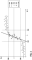
- figure 3 shows a result of the process for a new broadband lambda sensor without offset.
- the measured pump current Ip or the measured lambda is plotted on the x-axis.
- the dependent pump voltage Up is plotted on the Y-axis.
- the course of an exemplary reference characteristic curve 300 of the new broadband lambda probe is shown.
- the steep section of the reference characteristic curve 300 is defined by a pump current interval or lambda interval with a lower limit 302 and an upper limit 304 and by a pump voltage interval with a lower limit 306 and an upper limit 308 .
- the respective measured values 310, 312 for the measured pump current Ip or Lambda are also shown.
- Measured values outside the pump current or lambda interval and pump voltage interval are denoted by 310 and measured values within the pump current or lambda interval and pump voltage interval are denoted by 312 .
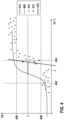
- figure 4 shows a result of the process for a new broadband lambda sensor with offset.
- the measured pump current Ip or the measured lambda is plotted on the x-axis.
- the dependent pump voltage Up is plotted on the Y-axis.
- the course of an exemplary reference characteristic curve 400 of the new broadband lambda probe is shown.
- the steep section of reference characteristic curve 400 is defined by a pump current interval or lambda interval with a lower limit 402 and an upper limit 404 and by a Pump voltage interval defined with a lower limit 406 and an upper limit 408.
- the respective measured values 410, 412 for the measured pump current Ip or Lambda are also shown.
- measured values outside the pump current or lambda interval and pump voltage interval are denoted by 410 and measured values within the pump current or lambda interval and pump voltage interval are denoted by 412 .
- figure 5 shows a result of the process on aged broadband lambda sensors with offset.
- the measured pump current Ip or the measured lambda is plotted on the x-axis.
- the dependent pump voltage Up is plotted on the Y-axis.
- the course of an exemplary reference characteristic curve 500 of a new broadband lambda probe is shown.
- the steep section of the reference characteristic curve 500 is defined by a pump current interval or lambda interval with a lower limit 502 and an upper limit 504 and by a pump voltage interval with a lower limit 506 and an upper limit 508 .
- a first curve 510 of the pump voltage Up as a function of Ip or Lambda of a first aged broadband lambda probe and a second curve 512 of the pump voltage Up as a function of Ip or Lambda are shown.
Landscapes
- Chemical & Material Sciences (AREA)
- Life Sciences & Earth Sciences (AREA)
- Health & Medical Sciences (AREA)
- Physics & Mathematics (AREA)
- General Physics & Mathematics (AREA)
- Biochemistry (AREA)
- Electrochemistry (AREA)
- Analytical Chemistry (AREA)
- Chemical Kinetics & Catalysis (AREA)
- General Health & Medical Sciences (AREA)
- Molecular Biology (AREA)
- Immunology (AREA)
- Pathology (AREA)
- Engineering & Computer Science (AREA)
- Combustion & Propulsion (AREA)
- Mechanical Engineering (AREA)
- General Engineering & Computer Science (AREA)
- Measuring Oxygen Concentration In Cells (AREA)
Description
- Aus dem Stand der Technik ist eine Vielzahl von Sensorelementen und Verfahren zur Erfassung mindestens einer Eigenschaft eines Messgases in einem Messgasraum bekannt. Dabei kann es sich grundsätzlich um beliebige physikalische und/oder chemische Eigenschaften des Messgases handeln, wobei eine oder mehrere Eigenschaften erfasst werden können. Die Erfindung wird im Folgenden insbesondere unter Bezugnahme auf eine qualitative und/oder quantitative Erfassung eines Anteils einer Gaskomponente des Messgases beschrieben, insbesondere unter Bezugnahme auf eine Erfassung eines Sauerstoffanteils in dem Messgas. Der Sauerstoffanteil kann beispielsweise in Form eines Partialdrucks und/oder in Form eines Prozentsatzes erfasst werden.
- Zusätzlich sind auch andere Eigenschaften des Messgases erfassbar, wie beispielsweise die Temperatur.
- Aus dem Stand der Technik sind insbesondere Sensoren mit keramischen Sensorelementen bekannt, welche auf der Verwendung von elektrolytischen Eigenschaften bestimmter Festkörper basieren, also auf Ionen leitenden Eigenschaften dieser Festkörper. Insbesondere kann es sich bei diesen Festkörpern um keramische Festelektrolyte handeln, wie beispielsweise Zirkoniumdioxid (ZrO2), insbesondere yttriumstabilisiertes Zirkoniumdioxid (YSZ) und scandiumdotiertes Zirkoniumdioxid (ScSZ), die geringe Zusätze an Aluminiumoxid (Al2O3) und/oder Siliziumoxid (SiO2) enthalten können.
- Beispielsweise können derartige Sensorelemente als so genannte Lambdasonden ausgestaltet sein, wie sie beispielsweise aus Konrad Reif (Hrsg.): Sensoren im Kraftfahrzeug, 1. Auflage 2010, S. 160-165, bekannt sind. Mit Breitbandlambdasonden, insbesondere mit planaren Breitbandlambdasonden, kann beispielsweise die Sauerstoffkonzentration im Abgas in einem großen Bereich bestimmt und damit auf das Luft-Kraftstoff-Verhältnis im Brennraum geschlossen werden. Die Luftzahl λ beschreibt dieses Luft-Kraftstoff-Verhältnis.
- Laut Gesetzgebung zur so genannten On Board Diagnose ist es gefordert, das Signal einer Breitbandlambdasonde zu überwachen. Ein zu überwachendes Fehlerbild ist dabei ein additiver Offset, vor allem in Benzin-Systemen bei stöchiometrischer Verbrennung (λ=1.0). Aktuell wird dieser Offset mit Hilfe einer Zwei-Punkt-Lambdasonde hinter dem Katalysator identifiziert, in dem bei aktiver Lambda=1-Regelung (Vor- und Hinterkatregelung aktiv) die Differenz des Lambdawerts der Sensoren vor und hinter Kat als Offset der Sonde vor dem Katalysator betrachtet wird. Dafür ist es notwendig, dass es in jedem Abgastrakt eine Lambdasonde vor dem Katalysator und eine Lambdasonde nach dem Katalysator gibt.
- Aus der
EP 0 444 674 B1 ist ein Verfahren bekannt, welches einen Offset der Breitbandlambdasonde vor dem Katalysator identifiziert, ohne dass eine zweite Lambdasonde hinter dem Katalysator als Referenz notwendig ist. Dies kann man als Selbstabgleich bezeichnen, da nur Signale der Breitbandlambdasonde selbst verwendet werden. Bei diesem Verfahren wird neben dem Pumpstromsignal, aus welchem der Lambdawert des Messgases berechnet wird, zusätzlich die Pumpspannung ausgewertet, wobei das Pumpspannungssignal als Referenz dient und angenommen wird, dass die Pumpspannung, insbesondere bei Lambda=1.0, keinen Alterungs- oder Störeffekten unterliegt. Durch Abgleich von Pumpstrom und Pumpspannung bei Lambda=1.0, was theoretisch einer Pumpspannung vom ungefähr 0 mV entspricht, wird hierbei auf einen Pumpstromoffset und damit auch einen Lambdaoffset geschlossen. - Aus der
DE 10 2013 202 161 A1 undDE 10 2013 202 260 A1 sind Verfahren bekannt, die ebenfalls auf dem Pumpstrom und der Pumpspannung basieren, aus beiden Größen aber je einen Lambdawert berechnen, wobei die Differenz dieser beiden Lambdawerte als Lambdaoffset der Breitbandlambdasonde interpretiert wird, wobei der Lambdawert berechnet aus der Pumpspannung als Referenz dient. - Trotz der Vorteile, der aus dem Stand der Technik bekannten Verfahren zum Betreiben von Breitbandlambdasonden, beinhalten diese noch Verbesserungspotenzial. So wird bei den genannten Verfahren direkt ein aus der Pumpspannung berechneter Pumpstrom oder Lambdawert mit dem gemessenen Pumpstrom oder dem daraus berechneten Lambdawert verglichen. Diese Verfahren benötigen einen Filter, um Störungen aus den gemessenen Signalen auszugleichen bzw. herauszumitteln.
- Es wird daher ein Verfahren zum Betreiben einer Breitbandlambdasonde vorgeschlagen, welches die Nachteile bekannter Verfahren zumindest weitgehend vermeidet und das insbesondere erlaubt, einen additiven Offset einer Breitbandlambdasonde zu identifizieren und gegebenenfalls zu adaptieren, wobei allein Signale der Lambdasonde selbst verwendet werden und kein weiterer Sensor, wie beispielsweise eine Lambdasonde, hinter dem Katalysator notwendig ist.
- Bei dem erfindungsgemäßen Verfahren zum Betreiben einer Breitbandlambdasonde, die ein keramisches Sensorelement aufweist, das eine elektrochemische Pumpzelle, eine elektrochemische Nernstzelle, eine Diffusionsbarriere und einen Hohlraum aufweist, wobei der Hohlraum über die Diffusionsbarriere mit einem Abgas kommuniziert, wobei die elektrochemische Pumpzelle eine äußere Pumpelektrode aufweist, die dem Abgas unmittelbar ausgesetzt ist, und eine innere Pumpelektrode aufweist, die in dem Hohlraum angeordnet ist, und einen zwischen der äußere Pumpelektrode und der inneren Pumpelektrode angeordneten ersten Festelektrolyten aufweist, wobei die elektrochemische Nernstzelle eine Nernstelektrode aufweist, die in dem Hohlraum angeordnet ist, und eine Referenzelektrode aufweist, die in einem Referenzgasraum angeordnet ist, und einen zwischen der Nernstelektrode und der Referenzelektrode angeordneten zweiten Festelektrolyten aufweist, wobei zwischen der äußeren Pumpelektrode und der inneren Pumpelektrode eine Pumpspannung anlegbar ist, so dass ein Pumpstrom fließt, wobei zwischen der Nernstelektrode und der Referenzelektrode eine Nernstspannung messbar ist, wobei basierend auf dem Pumpstrom ein Lambdawert eines Messgases erfassbar ist, umfasst das Verfahren die folgenden Schritte, bevorzugt in der angegebenen Reihenfolge:
- Regeln der Nernstspannung auf einen vorgegebenen Sollwert durch Stellen der Pumpspannung und/oder des Pumpstroms,
- Messen der Pumpspannung, des Pumpstroms und/oder des Lambdawerts,
- Bilden von Messwertpaaren basierend auf gemessenen Messwerten der Pumpspannung, des Pumpstroms und/oder des Lambdawerts,
- Berechnen einer Regressionsgeraden basierend auf den Messwertpaaren zum Approximieren eines vorbestimmten Abschnitts einer Referenzkennlinie der Pumpspannung, und
- Ermitteln eines Pumpstromoffsets und/oder Lambdaoffsets basierend auf der Regressionsgeraden.
- Der vorbestimmte Abschnitt der Referenzkennlinie kann ein Abschnitt mit einem steilen Verlauf sein. Unter einem steilen Verlauf kann ein Verlauf verstanden werden, dessen Steigung einen vorbestimmten Schwellwert überschreitet, wobei der vorbestimmte Schwellwert von null verschieden ist.
- Der Abschnitt mit dem steilen Verlauf kann durch ein Pumpstromintervall, Lambdaintervall und/oder Pumpspannungsintervall definiert ist. Somit wird der Abschnitt durch eine untere Grenze und eine obere Grenze für den Pumpstrom, das Lambda und/oder die Pumpspannung definiert.
- Das Pumpstromoffset und/oder Lambdaoffset können basierend auf einem Abstand der Regressionsgeraden von der Referenzkennlinie der Pumpspannung an einer vorbestimmten Stelle ermittelt werden. Beispielsweise ist die vorbestimmte Stelle ein Pumpstrom bei einer Pumpspannung von 0 mV oder ein Pumpstrom bei Lambda =1.
- Das Verfahren kann weiterhin Ermitteln von einem korrigierten Pumpstrom und/oder Lambdawerts basierend auf dem Pumpstromoffset und/oder Lambdaoffset umfassen. Damit wird die Messgenauigkeit erhöht.
- Alternativ oder zusätzlich kann das Verfahren weiterhin Durchführen einer Diagnose der Breitbandlambdasonde umfassen, wobei ein Fehler der Breitbandlambdasonde identifiziert wird, falls der Pumpstromoffset und/oder Lambdaoffset einen ersten vorbestimmten Schwellwert überschreitet oder einen zweiten vorbestimmten Schwellwert, der sich von dem ersten vorbestimmten Schwellwert unterscheidet, unterschreitet. Entsprechend kann der Pumpstromoffset und/oder Lambdaoffset als Diagnosekriterium verwendet werden, um einen Selbstabgleich durchzuführen, der den gesetzlich geforderten Vorgaben zur On Board Diagnose entspricht.
- Die Regressionsgerade kann mittels des Verfahrens der kleinsten Quadrate berechnet werden. Dabei kann das Berechnungsverfahren der kleinsten Quadrate rekursiv implementierbar sein. Durch Bilden der Regressionsgeraden können implizit Störungen aus den gemessenen Signalen ausgeglichen bzw. herausgemittelt werden, so dass kein weiterer Filter notwendig ist. Weiterhin kann die Regressionsgerade mit dem linearen Verfahren der kleinsten Quadrate ermittelt werden, was sich auch rekursiv implementieren lässt, so dass der Speicher- und Rechenbedarf z.B. in einem Motorsteuergerät gering ist.
- Die Messwertpaare können eine gemessene Pumpspannung Up abhängig vom Pumpstrom Ip, einen gemessenen Pumpstrom Ip abhängig von der Pumpspannung, eine gemessene Pumpspannung abhängig von Lambda oder gemessenes Lambda abhängig von der Pumpspannung Up umfassen. Mit anderen Worten wird aus mehreren Messwerten eine Regressionsgerade berechnet wie z.B. gemessene Pumpspannung Up abhängig vom Pumpstrom Ip oder umgekehrt oder gemessene Pumpspannung abhängig von Lambda oder umgekehrt.
- Weiterhin wird ein Computerprogramm vorgeschlagen, welches dazu eingerichtet ist, unter Verwendung einer Breitbandlambdasonde, jeden Schritt des Verfahrens nach einem der vorhergehenden Ausführungen durchzuführen.
- Weiterhin wird ein elektronisches Speichermedium vorgeschlagen, auf welchem ein solches Computerprogramm gespeichert ist.
- Weiterhin wird ein elektronisches Steuergerät vorgeschlagen, welches ein solches elektronisches Speichermedium umfasst.
- Ein Grundgedanke der vorliegenden Erfindung ist, dass weiterhin die Pumpspannung als Referenz dient, dass aber nicht direkt ein aus der Pumpspannung berechneter Pumpstrom oder Lambdawert mit dem gemessenen Pumpstrom oder dem daraus berechneten Lambdawert verglichen wird, sondern zunächst aus mehreren Messwerten eine Regressionsgerade berechnet wird. Die Regressionsgerade soll dabei den steilen Abschnitt einer für die Breitbandlambdasonde typischen Kennlinie abbilden. Der Abstand dieser Regressionsgeraden von einer nominalen Sensorkennlinie an einem typischen Punkt kann dann als Offset der Breitbandlambdasonde interpretiert werden.
- Vorteil der Erfindung ist, dass durch Bilden der Regressionsgeraden implizit Störungen aus den gemessenen Signalen ausgeglichen bzw. herausgemittelt werden, so dass kein weiterer Filter notwendig ist. Weiterhin kann die Regressionsgerade mit dem linearen Verfahren der kleinsten Quadrate ermittelt werden, was sich auch rekursiv implementieren lässt, so dass der Speicher- und Rechenbedarf z.B. in einem Motorsteuergerät gering ist.
- Außerdem ist das Verfahren anwendbar für Größen auf Basis Pumpstrom oder Lambda. Damit kann je nach Spezifikation der Breitbandlambdasonde die Regressionsgerade Pumpspannung = f(Pumpstrom) oder Pumpspannung = f(Lambda) berechnet und mit der auf derselben Basis spezifizierten nominalen Kennlinie verglichen werden.
- Da der Vergleichspunkt von Regressionsgerade und nominaler Kennlinie frei wählbar ist z.B. Pumpspannung = 0mV oder Pumpspannung bei λ=1, kann dieser vorteilhafterweise auf einen gut spezifizierbaren und stabilen Punkt der Kennlinie der Breitbandlambdasonde gelegt werden.
- Weitere optionale Einzelheiten und Merkmale der Erfindung ergeben sich aus der nachfolgenden Beschreibung bevorzugter Ausführungsbeispiele, welche in den Figuren schematisch dargestellt sind.
- Es zeigen:
- Figur 1
- eine Querschnittsansicht einer Breitbandlambdasonde,
- Figur 2
- exemplarisch ein Flussdiagramm des erfindungsgemäßen Verfahrens,
- Figur 3
- ein Ergebnis des Verfahrens bei einer neuen Breitbandlambdasonde ohne Offset,
- Figur 4
- ein Ergebnis des Verfahrens bei einer neuen Breitbandlambdasonde mit Offset und
- Figur 5
- ein Ergebnis des Verfahrens bei gealterten Breitbandlambdasonden mit Offset.
- In
Figur 1 zeigt eine Querschnittsansicht einer Breitband-Lambda-Sonde 110. Die Breitband-Lambda-Sonde 110 ist mit einem elektronischen Steuergerät 124 verbunden. Die Breitband-Lambda-Sonde 110 umfasst ein Sensorelement 112. Das Sensorelement 112 weist eine elektrochemische Pumpzelle 116 mit einer äußeren Pumpelektrode 118 und einer inneren Pumpelektrode 118' und einem dazwischen angeordneten Festelektrolyten 120 auf. Die äußere Pumpelektrode 118 ist von einem Messgas114, wie beispielsweise Abgas, lediglich durch eine Schutzschicht getrennt, unmittelbar ausgesetzt, die innere Pumpelektrode 118' ist in einem inneren Hohlraum 130 des Sensorelements 112 angeordnet. Der Zutritt des Gases zu dem Hohlraum 130 bzw. zu der in ihm angeordneten Elektrode 118 ist durch eine poröse Diffusionsbarriere 128 limitiert. - Das Sensorelement 112 weist eine elektrochemische Nernstzelle 216 mit einer Nernstelektrode 218 und einer in einem Referenzkanal 219 angeordneten Referenzelektrode 218` auf, die durch den zweiten Festelektrolyten 120' miteinander verbunden sind. Das Sensorelement 112 umfasst ferner ein als elektrische Widerstandheizung ausgebildetes Heizelement 122.
- Das elektronische Steuergerät 124 ist eingerichtet, um das erfindungsgemäße Verfahren zum Betrieb der Breitbandlambdasonde durchzuführen, insbesondere um eine aktivierbare und/oder deaktivierbare äußere elektrische Beschaltung zu realisieren, durch die elektrische Spannungen und/oder elektrische Ströme in die elektrochemische Pumpzelle 116, die elektrochemische Nernstzelle 216 und/oder das Heizelement 122 einprägbar sind. Überdies kann das Steuergerät 124 eingerichtet sein, die Bestimmung einer Temperatur des Sensorelements 112 und/oder der elektrochemischen Pumpzelle 116 und/oder der elektrochemischen Nernstzelle 216 vorzunehmen, beispielsweise durch entsprechende Widerstandsmessungen oder dergleichen. Das elektronische Steuergerät 124 kann zu diesem Zweck mindestens eine Datenverarbeitungsvorrichtung 126 umfassen. Weiterhin kann das elektronische Steuergerät 124 ein elektronisches Speichermedium umfassen, auf dem ein Computerprogramm gespeichert ist, das Anweisungen zum Durchführen der einzelnen Verfahrensschritte umfasst. Das Sensorelement 112 kann über mindestens eine Schnittstelle 134 mit dem elektronischen Steuergerät 124 und/oder mit der Datenverarbeitungsvorrichtung 126 verbunden sein. Insbesondere ist zwischen der äußeren Pumpelektrode 118 und der inneren Pumpelektrode 118` eine Pumpspannung Up anlegbar, sodass ein Pumpstrom Ip fließt, und zwischen der Nernstelektrode 218 und der Referenzelektrode 218` eine Nernstspannung Un messbar.
- Nachfolgend wird das erfindungsgemäße Verfahren beschrieben. Der Betrieb der Lambdasonde 110 beginnt, nachdem das Sensorelement 112 ausreichend aufgeheizt ist, beispielsweise nachdem mittels der elektrischen Widerstandsheizung eine Betriebstemperatur zwischen 700°C und 800°C eingeregelt ist. Die Temperatur des Sensorelements 112 und damit der Innenwiderstand der elektrochemischen Zellen 116, 216 wird nachfolgend weiterhin stets auf diese Temperatur geregelt.
- Im Betrieb der Breitbandlambdasonde wird die Nernstspannung Un stets auf einen vorgegebenen Sollwert, beispielsweise 450mV geregelt, wie in Schritt S10 angegeben ist. Hierzu wird die Pumpspannung Up und/oder der Pumpstroms Ip durch einen Regelalgorithmus geeignet gestellt. Es wird somit in dem inneren Hohlraum 130 ein Gasgemisch mit einer vorgegebenen Luftzahl eingestellt, beispielsweise Lambda = 1. Dieser Pumpstrom Ip fließt physikalisch als lonenstrom in der elektrochemischen Pumpzelle 116 und als Elektronenstrom in deren Zuleitung und ist grundsätzlich bereits ein Maß für den Partialdruck des Sauerstoffs im Messgas 114, wie beispielsweise Abgas, also für Lambda. Basierend auf dem Pumpstrom Ip ist somit ein Lambdawert des Messgases 114 erfassbar. Die Grundlage für das Einstellen der Spannung an so genannten Nernstzellen ist das chemische Potential. Dieses ist jedoch gegenüber einem definierten Fix-Potential anzugeben. Innerhalb der Lambdasonde 110 existiert ein im Normalfall klar definiertes chemisches Potential an dem RE-Anschluss der Lambdasonde, wo sich die sogenannte Luft-Referenz befindet. Auf diese Luft-Referenz beziehen sich alle weiteren Potentiale des Lambda-Sensors inklusive dem Potential am IPE-Pin, wo sich der sogenannte Lambda-1-Hohlraum 130 befindet, dessen chemisches Potential über eine Differenzspannung von 450mV so eingestellt wird, dass sich dort der Lambda-Wert von 1 einstellt. Die bisher benannte Pumpspannung Up ist die Spannung des APE-Pins gegenüber dem IPE-Pin. Da sich jedoch der IPE-Pin auf ein Potential am RE-Pin bezieht, könnte bei dem Verfahren statt der Pumpspannung Up auch die Spannung zwischen APE-Pin und RE-Pin verwendet werden, die in diesem Fall als Sensor-internes Signal einer binären Lambdasonde bezeichnet werden kann.
- In Schritt S12 wird die Pumpspannung Up, der Pumpstrom Ip und/oder der Lambdawert des Messgases gemessen, beispielsweise erfasst. Die dadurch erfassten Messwerte werden zumindest vorübergehend gespeichert.
- Basierend auf den gemessenen Messwerten der Pumpspannung Up, des Pumpstroms Ip und/oder des Lambdawerts des Messgases werden in Schritt S14 Messwertpaare gebildet.
- In Schritt S16 wird basierend auf den Messwertpaaren eine Regressionsgerade zum Approximieren eines vorbestimmten Abschnitts einer Referenzkennlinie der Pumpspannung Up berechnet. So wird aus mehreren Messwertpaaren wie beispielsweise gemessene Pumpspannung Up abhängig vom Pumpstrom Ip oder umgekehrt oder gemessene Pumpspannung Up abhängig von Lambda λ oder umgekehrt eine Regressionsgerade berechnet. Der vorbestimmte Abschnitt der Referenzkennlinie kann ein Abschnitt mit einem steilen Verlauf sein, d.h. ein Abschnitt mit einer Steigung, die deutlich größer, d.h. beispielsweise mindestens Faktor 3 und beispielsweise bevorzugt mindestens Faktor 5, als in übrigen Abschnitten der Kennlinie ist. Ein solch steiler Verlauf ist für Lambdasonden typisch und allgemein bekannt. Die Regressionsgerade soll somit den steilen Abschnitt einer für die Breitbandlambdasonde typischen Funktion Up = f(lp) oder Up=f(λ) abbilden. Der Abschnitt mit dem steilen Verlauf kann durch ein Pumpstromintervall, Lambdaintervall und/oder Pumpspannungsintervall definiert sein. Mit anderen Worten kann der steile Abschnitt dabei anhand der spezifizierten nominalen Kennlinie durch ein Pumpstromintervall oder LambdaIntervall und/oder ein Pumpspannungsintervall definiert werden.
- Zur Schätzung der Regressionsgeraden können zum einen Messwertpaare aus dem definierten Up/Ip- oder Up/λ-Intervall zunächst zwischengespeichert und dann eine lineare Regression mit dem Verfahren der kleinsten Quadrate in einem Rechenschritt durchgeführt werden. Alternativ ist die Berechnung auch rekursiv möglich, wodurch Speicher- und Rechenbedarf reduziert wird. Dabei kann sowohl Up abhängig von Ip oder λ berechnet werden oder auch der umgekehrte Zusammenhang, je nachdem welche Größe als stärker verrauscht betrachtet wird. Annahme des Verfahrens der kleinsten Quadrate ist nämlich, dass nur die abhängige Größe (Y-Achse) gestört ist. Da hier jedoch sowohl die Pumpspannung als auch der Pumpstrom oder Lambda gemessen und damit gestört sind, kann auch das Verfahren der totalen kleinsten Quadrate vorteilhaft verwendet werden, welches Störungen sowohl auf X-Achse als auch auf der Y-Achse bei der Parameterschätzung berücksichtigen kann.
- In Schritt S18 wird basierend auf der Regressionsgeraden ein Pumpstromoffset und/oder Lambdaoffset ermittelt. Insbesondere wird Der Pumpstromoffset und/oder Lambdaoffset basierend auf einem Abstand der Regressionsgeraden von der Referenzkennlinie der Pumpspannung an einer vorbestimmten Stelle ermittelt. Die vorbestimmte Stelle ist beispielsweise ein Pumpstrom bei einer Pumpspannung von 0 mV oder ein Pumpstrom bei Lambda = 1. Mit anderen Worten kann der Abstand dieser Regressionsgeraden von einer nominalen Sensorkennlinie an einem typischen Punkt, wie z.B. horizontaler Abstand von Regressionsgerade zu nominaler Sensorkennlinie Up=f(lp) bei Up=0mV oder Up bei λ=1, dann als Offset, wie z.B. Pumpstrom oder Lambdaoffset, interpretiert werden.
- In Schritt S20 wird basierend auf dem Pumpstromoffset und/oder Lambdaoffset ein korrigierter Pumpstrom und/oder Lambdawert ermittelt, beispielsweise durch Subtraktion oder Addition von dem gemessenen Pumpstrom Ip oder Lambda. Der mit diesem Verfahren ermittelte Pumpstromoffset oder Lambdaoffset kann somit direkt zur Adaption und Korrektur des fehlerhaften Pumpstromsignals oder Lambdasignals verwendet werden.
- Weiterhin kann in Schritt S22 optional eine Diagnose der Breitbandlambdasonde 110 durchgeführt werden, wobei ein Fehler der Breitbandlambdasonde 110 identifiziert wird, falls der Pumpstromoffset und/oder Lambdaoffset einen ersten vorbestimmten Schwellwert überschreitet oder einen zweiten vorbestimmten Schwellwert, der sich von dem ersten vorbestimmten Schwellwert unterscheidet, unterschreitet. Weiterhin kann somit der identifizierte Pumpstromoffset zur Diagnose der Breitbandlambdasonde 110 verwendet werden, indem ein Fehlereintrag erfolgt, wenn der identifizierte Pumpstromoffset oder Lambdaoffset größer oder kleiner spezifizierter Schwellwerte ist.
- Die Verwendung der Erfindung kann nachgewiesen werden, wenn z.B. beim Einbringen eines Leckstroms oder einer Einkopplung auf den Pumpstrom ein Fehler erkannt wird. Dieser wird dann durch das Steuergerät eingetragen und über die Diagnose-Schnittstelle messbar gemacht.
-
Figur 3 zeigt ein Ergebnis des Verfahrens bei einer neuen Breitbandlambdasonde ohne Offset. Bei dem gezeigten Beispiel ist auf der X-Achse der gemessene Pumpstrom Ip oder das gemessene Lambda aufgetragen. Auf der Y-Achse ist die davon abhängige Pumpspannung Up aufgetragen. Weiterhin ist der Verlauf einer beispielhaften Referenzkennlinie 300 der neuen Breitbandlambdasonde dargestellt. Der steile Abschnitt der Referenzkennlinie 300 ist durch ein Pumpstromintervall oder Lambdaintervall mit einer unteren Grenze 302 und einer oberen Grenze 304 sowie durch ein Pumpspannungsintervall mit einer unteren Grenze 306 und einer oberen Grenze 308 definiert. Die jeweiligen Messwerte 310, 312 für den gemessenen Pumpstrom Ip bzw. Lambda sind ebenfalls dargestellt. Dabei sind Messwerte außerhalb des Pumpstrom- bzw. Lambdaintervalls und Pumpspannungsintervalls mit 310 bezeichnet und Messwerte innerhalb des Pumpstrom- bzw. Lambdaintervalls und Pumpspannungsintervalls sind mit 312 bezeichnet. Die so berechnete Regressionsgerade 314 ist ebenfalls dargestellt. Da es sich bei dem Beispiel inFigur 3 um eine neue Breitbandlambdasonde ohne Offset handelt, ist ein horizontaler Abstand 316 der Regressionsgeraden 314 von der Referenzkennlinie 300 an einer vorbestimmten Stelle innerhalb des Abschnitts mit dem steilen Verlauf, wie beispielsweise bei einer Pumpspannung Up =0 mV, ebenfalls null, was keinen Offset anzeigt. -
Figur 4 zeigt ein Ergebnis des Verfahrens bei einer neuen Breitbandlambdasonde mit Offset. Bei dem gezeigten Beispiel ist auf der X-Achse der gemessene Pumpstrom Ip oder das gemessene Lambda aufgetragen. Auf der Y-Achse ist die davon abhängige Pumpspannung Up aufgetragen. Weiterhin ist der Verlauf einer beispielhaften Referenzkennlinie 400 der neuen Breitbandlambdasonde dargestellt. Der steile Abschnitt der Referenzkennlinie 400 ist durch ein Pumpstromintervall oder Lambdaintervall mit einer unteren Grenze 402 und einer oberen Grenze 404 sowie durch ein Pumpspannungsintervall mit einer unteren Grenze 406 und einer oberen Grenze 408 definiert. Die jeweiligen Messwerte 410, 412 für den gemessenen Pumpstrom Ip bzw. Lambda sind ebenfalls dargestellt. Dabei sind Messwerte außerhalb des Pumpstrom- bzw. Lambdaintervalls und Pumpspannungsintervalls mit 410 bezeichnet und Messwerte innerhalb des Pumpstrom- bzw. Lambdaintervalls und Pumpspannungsintervalls sind mit 412 bezeichnet. Die so berechnete Regressionsgerade 414 ist ebenfalls dargestellt. Da es sich bei dem Beispiel inFigur 4 um eine neue Breitbandlambdasonde mit Offset handelt, ist ein horizontaler Abstand 416 der Regressionsgeraden 414 von der Referenzkennlinie 400 an einer vorbestimmten Stelle innerhalb des Abschnitts mit dem steilen Verlauf, wie beispielsweise bei einer Pumpspannung Up =0 mV, von null verschieden, was einen Offset anzeigt. -
Figur 5 zeigt ein Ergebnis des Verfahrens bei gealterten Breitbandlambdasonden mit Offset. Bei dem gezeigten Beispiel ist auf der X-Achse der gemessene Pumpstrom Ip oder das gemessene Lambda aufgetragen. Auf der Y-Achse ist die davon abhängige Pumpspannung Up aufgetragen. Weiterhin ist der Verlauf einer beispielhaften Referenzkennlinie 500 einer neuen Breitbandlambdasonde dargestellt. Der steile Abschnitt der Referenzkennlinie 500 ist durch ein Pumpstromintervall oder Lambdaintervall mit einer unteren Grenze 502 und einer oberen Grenze 504 sowie durch ein Pumpspannungsintervall mit einer unteren Grenze 506 und einer oberen Grenze 508 definiert. Weiterhin sind ein erster Verlauf 510 der Pumpspannung Up abhängig von Ip oder Lambda einer ersten gealterten Breitbandlambdasonde sowie ein zweiter Verlauf 512 der Pumpspannung Up abhängig von Ip oder Lambda dargestellt. Eine berechnete erste Regressionsgerade 514 der ersten gealterten Breitbandlambdasonde und eine berechnete zweite Regressionsgerade 516 der zweiten gealterten Breitbandlambdasonde sind ebenfalls dargestellt. Da es sich bei dem Beispiel inFigur 5 um gealterte Breitbandlambdasonden mit Offset handelt, ist ein horizontaler Abstand 518 von beispielsweise der zweiten Regressionsgeraden 516 von der Referenzkennlinie 500 an einer vorbestimmten Stelle innerhalb des Abschnitts mit dem steilen Verlauf, wie beispielsweise bei einer Pumpspannung Up =0 mV von null verschieden, was einen Offset anzeigt.
Claims (12)
- Verfahren zum Betreiben einer Breitbandlambdasonde (110), wobei die Breitbandlambdasonde (110) ein keramisches Sensorelement (112) aufweist, das eine elektrochemische Pumpzelle (116), eine elektrochemische Nernstzelle (216), eine Diffusionsbarriere (128) und einen Hohlraum (130) aufweist, wobei der Hohlraum (130) über die Diffusionsbarriere (128) mit einem Abgas (114) kommuniziert, wobei die elektrochemische Pumpzelle (116) eine äußere Pumpelektrode (118) aufweist, die dem Abgas (114) unmittelbar ausgesetzt ist, und eine innere Pumpelektrode (118`) aufweist, die in dem Hohlraum (130) angeordnet ist, und einen zwischen der äußere Pumpelektrode (118) und der inneren Pumpelektrode (118`) angeordneten ersten Festelektrolyten (120) aufweist, wobei die elektrochemische Nernstzelle (216) eine Nernstelektrode (218) aufweist, die in dem Hohlraum (130) angeordnet ist, und eine Referenzelektrode (218`) aufweist, die in einem Referenzgasraum (219) angeordnet ist, und einen zwischen der Nernstelektrode (218) und der Referenzelektrode (218`) angeordneten zweiten Festelektrolyten (120`) aufweist, wobei zwischen der äußeren Pumpelektrode (118) und der inneren Pumpelektrode (118') eine Pumpspannung (Up) anlegbar ist, so dass ein Pumpstrom (Ip) fließt, wobei zwischen der Nernstelektrode (218) und der Referenzelektrode (218') eine Nernstspannung (Un) messbar ist, wobei basierend auf dem Pumpstrom ein Lambdawert (λ) eines Messgases erfassbar ist, wobei das Verfahren die folgenden Schritte umfasst:- Regeln der Nernstspannung (Un) auf einen vorgegebenen Sollwert durch Stellen der Pumpspannung (Up) und/oder des Pumpstroms (Ip),- Messen der Pumpspannung (Up), des Pumpstroms (Ip) und/oder des Lambdawerts (λ),- Bilden von Messwertpaaren basierend auf gemessenen Messwerten der Pumpspannung (Up), des Pumpstroms (Ip) und/oder des Lambdawerts (λ),- Berechnen einer Regressionsgeraden (314, 414, 514, 516) basierend auf den Messwertpaaren zum Approximieren eines vorbestimmten Abschnitts einer Referenzkennlinie (300, 400, 500) der Pumpspannung (Up), und- Ermitteln eines Pumpstromoffsets und/oder Lambdaoffsets basierend auf der Regressionsgeraden (314, 414, 514, 516).
- Verfahren nach dem vorhergehenden Anspruch, wobei der vorbestimmte Abschnitt der Referenzkennlinie (300, 400, 500) ein Abschnitt mit einem steilen Verlauf ist.
- Verfahren nach dem vorhergehenden Anspruch, wobei der Abschnitt mit dem steilen Verlauf durch ein Pumpstromintervall, Lambdaintervall und/oder Pumpspannungsintervall definiert ist.
- Verfahren nach einem der vorhergehenden Ansprüche, weiterhin umfassend Ermitteln des Pumpstromoffsets und/oder Lambdaoffsets basierend auf einem Abstand der Regressionsgeraden (314, 414, 514, 516) von der Referenzkennlinie (300, 400, 500) der Pumpspannung (Up) an einer vorbestimmten Stelle.
- Verfahren nach dem vorhergehenden Anspruch, wobei die vorbestimmte Stelle ein Pumpstrom (Ip) bei einer Pumpspannung (Up) von 0 mV oder ein Pumpstrom (Ip) bei Lambda =1 ist.
- Verfahren nach einem der vorhergehenden Ansprüche, weiterhin umfassend Ermitteln von einem korrigierten Pumpstrom und/oder Lambdawerts basierend auf dem Pumpstromoffset und/oder Lambdaoffset.
- Verfahren nach einem der vorhergehenden Ansprüche, weiterhin umfassend Durchführen einer Diagnose der Breitbandlambdasonde (110), wobei ein Fehler der Breitbandlambdasonde (110) identifiziert wird, falls der Pumpstromoffset und/oder Lambdaoffset einen ersten vorbestimmten Schwellwert überschreitet oder einen zweiten vorbestimmten Schwellwert, der sich von dem ersten vorbestimmten Schwellwert unterscheidet, unterschreitet.
- Verfahren nach einem der vorhergehenden Ansprüche, wobei die Regressionsgerade (314, 414, 514, 516) mittels des Verfahrens der kleinsten Quadrate berechnet wird, wobei das Verfahren der kleinsten Quadrate bevorzugt rekursiv implementierbar ist.
- Verfahren nach einem der vorhergehenden Ansprüche, wobei die Messwertpaare eine gemessene Pumpspannung (Up) abhängig vom Pumpstrom (Ip), einen gemessenen Pumpstrom (Ip) abhängig von der Pumpspannung (Up), eine gemessene Pumpspannung (Up) abhängig von Lambda oder gemessenes Lambda abhängig von der Pumpspannung (Up) umfassen.
- Computerprogramm, welches dazu eingerichtet ist, unter Verwendung einer Breitbandlambdasonde, jeden Schritt des Verfahrens nach einem der vorhergehenden Ansprüche durchzuführen.
- Elektronisches Speichermedium, auf welchem ein Computerprogramm nach dem vorhergehenden Anspruch gespeichert ist.
- Elektronisches Steuergerät, welches ein elektronisches Speichermedium nach dem vorhergehenden Anspruch umfasst.
Applications Claiming Priority (2)
| Application Number | Priority Date | Filing Date | Title |
|---|---|---|---|
| DE102019215819.6A DE102019215819A1 (de) | 2019-10-15 | 2019-10-15 | Verfahren zum Betreiben einer Breitbandlambdasonde |
| PCT/EP2020/076374 WO2021073837A1 (de) | 2019-10-15 | 2020-09-22 | Verfahren zum betreiben einer breitbandlambdasonde |
Publications (2)
| Publication Number | Publication Date |
|---|---|
| EP4045902A1 EP4045902A1 (de) | 2022-08-24 |
| EP4045902B1 true EP4045902B1 (de) | 2023-08-23 |
Family
ID=72670680
Family Applications (1)
| Application Number | Title | Priority Date | Filing Date |
|---|---|---|---|
| EP20781450.0A Active EP4045902B1 (de) | 2019-10-15 | 2020-09-22 | Verfahren zum betreiben einer breitbandlambdasonde |
Country Status (5)
| Country | Link |
|---|---|
| US (1) | US12535459B2 (de) |
| EP (1) | EP4045902B1 (de) |
| CN (1) | CN114556095B (de) |
| DE (1) | DE102019215819A1 (de) |
| WO (1) | WO2021073837A1 (de) |
Families Citing this family (3)
| Publication number | Priority date | Publication date | Assignee | Title |
|---|---|---|---|---|
| DE102022202504A1 (de) | 2022-03-14 | 2023-01-26 | Vitesco Technologies GmbH | Verfahren zur Diagnose eines Abgassensors für eine Brennkraftmaschine, Abgassensor und Brennkraftmaschine |
| DE102022114808B3 (de) * | 2022-06-13 | 2023-06-07 | Dr. Ing. H.C. F. Porsche Aktiengesellschaft | Verfahren zum Selbstabgleich einer Lambdasonde und Abgasstrang |
| DE102024200974A1 (de) * | 2024-02-02 | 2025-08-07 | Dr. Ing. H.C. F. Porsche Aktiengesellschaft | Verfahren zum Betreiben eines Sensorelements zur Erfassung mindestens einer Eigenschaft eines Messgases in einem Messgasraum |
Family Cites Families (13)
| Publication number | Priority date | Publication date | Assignee | Title |
|---|---|---|---|---|
| DE69118739T2 (de) | 1990-02-28 | 1996-08-29 | Mitsubishi Motors Corp | Detektionsvorrichtung für das Luft-Kraftstoff-Verhältnis |
| DE10147390A1 (de) * | 2001-09-26 | 2003-04-30 | Bosch Gmbh Robert | Breitband-Lambda-Sonde mit verbessertem Startverhalten |
| JP2003219565A (ja) | 2002-01-18 | 2003-07-31 | Nec Machinery Corp | 電池充放電システムの校正方法及び校正装置 |
| DE102007035318A1 (de) * | 2007-07-27 | 2009-01-29 | Robert Bosch Gmbh | Verfahren und Schaltungsanordnung zum Betreiben einer Breitbandlambdasonde |
| DE102008004359A1 (de) * | 2008-01-15 | 2009-07-16 | Robert Bosch Gmbh | Verfahren zum Betreiben eines Sensorelements zur Bestimmung der Konzentration von Gaskomponenten |
| JP5323752B2 (ja) | 2009-03-30 | 2013-10-23 | 日本碍子株式会社 | ガスセンサのポンプ電極、導電性ペーストの製造方法、およびガスセンサ |
| DE102011005694A1 (de) * | 2011-03-17 | 2012-09-20 | Robert Bosch Gmbh | Verfahren zur in-situ-Kalibrierung eines Sensorelements |
| DE102012206140A1 (de) * | 2012-04-16 | 2013-10-17 | Robert Bosch Gmbh | Verfahren zur Erfassung eines Sauerstoffanteils in einem Messgasraum |
| DE102013221298A1 (de) | 2012-10-22 | 2014-04-24 | Robert Bosch Gmbh | Verfahren zum Abgleichen eines Sensorelements zur Erfassung mindestens einer Eigenschaft eines Messgases in einem Messgasraum |
| DE102012219282A1 (de) * | 2012-10-23 | 2014-04-24 | Robert Bosch Gmbh | Verfahren und Vorrichtung zur Diagnose des Luftreferenzkanals einer Breitband-Lambdasonde |
| DE102013202161A1 (de) * | 2013-02-11 | 2014-08-14 | Continental Automotive Gmbh | Verfahren und Vorrichtung zum Betreiben einer linearen Lambdasonde |
| DE102013202260A1 (de) | 2013-02-12 | 2014-08-14 | Robert Bosch Gmbh | Verfahren und Vorrichtung zur Überwachung eines mehrzelligen Abgassensors |
| DE102014007168B4 (de) * | 2014-05-15 | 2020-03-05 | Audi Ag | Verfahren zum Betreiben einer Abgasanlage für eine Brennkraftmaschine sowie entsprechende Abgasanlage |
-
2019
- 2019-10-15 DE DE102019215819.6A patent/DE102019215819A1/de not_active Withdrawn
-
2020
- 2020-09-22 WO PCT/EP2020/076374 patent/WO2021073837A1/de not_active Ceased
- 2020-09-22 CN CN202080072711.3A patent/CN114556095B/zh active Active
- 2020-09-22 EP EP20781450.0A patent/EP4045902B1/de active Active
- 2020-09-22 US US17/766,360 patent/US12535459B2/en active Active
Also Published As
| Publication number | Publication date |
|---|---|
| WO2021073837A1 (de) | 2021-04-22 |
| DE102019215819A1 (de) | 2021-04-15 |
| US12535459B2 (en) | 2026-01-27 |
| CN114556095A (zh) | 2022-05-27 |
| CN114556095B (zh) | 2024-07-26 |
| US20240053296A1 (en) | 2024-02-15 |
| EP4045902A1 (de) | 2022-08-24 |
Similar Documents
| Publication | Publication Date | Title |
|---|---|---|
| EP3465195B1 (de) | Verfahren zur dynamiküberwachung eines nox-sensors | |
| EP2625580B1 (de) | Verfahren zur einstellung einer temperatur eines sensorelements | |
| DE102009047648B4 (de) | Verfahren und Vorrichtung zur Diagnose von Abweichungen bei einer Einzelzylinder-Lambdaregelung | |
| WO2018166677A1 (de) | Verfahren zum betreiben eines sensors zur erfassung mindestens einer eigenschaft eines messgases in einem messgasraum | |
| WO2021073837A1 (de) | Verfahren zum betreiben einer breitbandlambdasonde | |
| DE102010040147A1 (de) | Verfahren und Vorrichtung zur Erfassung mindestens einer Eigenschaft eines Gases | |
| WO2012028380A1 (de) | Verfahren und vorrichtung zur erfassung mindestens einer eigenschaft eines gases | |
| EP3289347B1 (de) | Verfahren und vorrichtung zur bestimmung eines innenwiderstandes eines sensorelements | |
| DE19625899C2 (de) | Verfahren zum Betreiben einer Sauerstoffsonde | |
| WO2020011652A1 (de) | Verfahren zum betreiben eines auf festelektrolyten basierenden elektrochemischen sensors | |
| EP3622281B1 (de) | Verfahren zur bestimmung der temperatur eines festelektrolyt-gassensors | |
| DE102012224374A1 (de) | Verfahren zur Diagnose einer elektrischen Leitung zu einer Elektrode eines Sensorelements zur Erfassung mindestens einer Eigenschaft eines Messgases in einem Messgasraum | |
| DE102012200038A1 (de) | Verfahren und Steuereinheit zur Korrektur der Nernstspannung einer Nernstzelle | |
| WO2024083431A1 (de) | Verfahren zum betreiben eines sensors zur erfassung mindestens einer eigenschaft eines messgases in einem messgasraum | |
| WO2024068533A1 (de) | Diagnose-verfahren zum betreiben eines sensors zum nachweis mindestens eines anteils einer messgaskomponente mit gebundenem sauerstoff in einem messgas | |
| DE102014205383A1 (de) | Verfahren zum Betrieb einer Sensorvorrichtung | |
| DE102017209300A1 (de) | Verfahren zur Bestimmung eines Zustandes mindestens einer Komponente eines Sensors zur Erfassung mindestens einer Eigenschaft eines Messgases in einem Messgasraum | |
| DE102011017015B4 (de) | Verfahren zum Betreiben einer Lambdasonde | |
| DE102015201396A1 (de) | Sensor zur Erfassung mindestens einer Eigenschaft eines Messgases in einem Messgasraum | |
| DE112019004369T5 (de) | Steuervorrichtung | |
| DE102022211385A1 (de) | Verfahren zum Betreiben eines Sensors zur Erfassung mindestens einer Eigenschaft eines Messgases in einem Messgasraum einer Brennkraftmaschine | |
| DE102024101872A1 (de) | Einrichtung und Verfahren zum Überprüfen eines elektrochemischen Sensors | |
| DE102024203698A1 (de) | Verfahren zur Diagnose eines Abgassensors | |
| WO2023099253A1 (de) | Verfahren zum betreiben eines sensors zum bestimmen mindestens eines anteils eines gases in einem messgasraum | |
| DE102021213479A1 (de) | Verfahren zum Betreiben eines Sensors zum Bestimmen mindestens eines Anteils eines Gases in einem Messgasraum |
Legal Events
| Date | Code | Title | Description |
|---|---|---|---|
| STAA | Information on the status of an ep patent application or granted ep patent |
Free format text: STATUS: UNKNOWN |
|
| STAA | Information on the status of an ep patent application or granted ep patent |
Free format text: STATUS: THE INTERNATIONAL PUBLICATION HAS BEEN MADE |
|
| PUAI | Public reference made under article 153(3) epc to a published international application that has entered the european phase |
Free format text: ORIGINAL CODE: 0009012 |
|
| STAA | Information on the status of an ep patent application or granted ep patent |
Free format text: STATUS: REQUEST FOR EXAMINATION WAS MADE |
|
| 17P | Request for examination filed |
Effective date: 20220516 |
|
| AK | Designated contracting states |
Kind code of ref document: A1 Designated state(s): AL AT BE BG CH CY CZ DE DK EE ES FI FR GB GR HR HU IE IS IT LI LT LU LV MC MK MT NL NO PL PT RO RS SE SI SK SM TR |
|
| DAV | Request for validation of the european patent (deleted) | ||
| DAX | Request for extension of the european patent (deleted) | ||
| GRAP | Despatch of communication of intention to grant a patent |
Free format text: ORIGINAL CODE: EPIDOSNIGR1 |
|
| STAA | Information on the status of an ep patent application or granted ep patent |
Free format text: STATUS: GRANT OF PATENT IS INTENDED |
|
| INTG | Intention to grant announced |
Effective date: 20230525 |
|
| GRAS | Grant fee paid |
Free format text: ORIGINAL CODE: EPIDOSNIGR3 |
|
| GRAA | (expected) grant |
Free format text: ORIGINAL CODE: 0009210 |
|
| STAA | Information on the status of an ep patent application or granted ep patent |
Free format text: STATUS: THE PATENT HAS BEEN GRANTED |
|
| AK | Designated contracting states |
Kind code of ref document: B1 Designated state(s): AL AT BE BG CH CY CZ DE DK EE ES FI FR GB GR HR HU IE IS IT LI LT LU LV MC MK MT NL NO PL PT RO RS SE SI SK SM TR |
|
| REG | Reference to a national code |
Ref country code: GB Ref legal event code: FG4D Free format text: NOT ENGLISH |
|
| REG | Reference to a national code |
Ref country code: CH Ref legal event code: EP |
|
| REG | Reference to a national code |
Ref country code: DE Ref legal event code: R096 Ref document number: 502020004896 Country of ref document: DE |
|
| REG | Reference to a national code |
Ref country code: IE Ref legal event code: FG4D Free format text: LANGUAGE OF EP DOCUMENT: GERMAN |
|
| REG | Reference to a national code |
Ref country code: LT Ref legal event code: MG9D |
|
| REG | Reference to a national code |
Ref country code: NL Ref legal event code: MP Effective date: 20230823 |
|
| PG25 | Lapsed in a contracting state [announced via postgrant information from national office to epo] |
Ref country code: GR Free format text: LAPSE BECAUSE OF FAILURE TO SUBMIT A TRANSLATION OF THE DESCRIPTION OR TO PAY THE FEE WITHIN THE PRESCRIBED TIME-LIMIT Effective date: 20231124 |
|
| PG25 | Lapsed in a contracting state [announced via postgrant information from national office to epo] |
Ref country code: IS Free format text: LAPSE BECAUSE OF FAILURE TO SUBMIT A TRANSLATION OF THE DESCRIPTION OR TO PAY THE FEE WITHIN THE PRESCRIBED TIME-LIMIT Effective date: 20231223 |
|
| PG25 | Lapsed in a contracting state [announced via postgrant information from national office to epo] |
Ref country code: SE Free format text: LAPSE BECAUSE OF FAILURE TO SUBMIT A TRANSLATION OF THE DESCRIPTION OR TO PAY THE FEE WITHIN THE PRESCRIBED TIME-LIMIT Effective date: 20230823 Ref country code: RS Free format text: LAPSE BECAUSE OF FAILURE TO SUBMIT A TRANSLATION OF THE DESCRIPTION OR TO PAY THE FEE WITHIN THE PRESCRIBED TIME-LIMIT Effective date: 20230823 Ref country code: PT Free format text: LAPSE BECAUSE OF FAILURE TO SUBMIT A TRANSLATION OF THE DESCRIPTION OR TO PAY THE FEE WITHIN THE PRESCRIBED TIME-LIMIT Effective date: 20231226 Ref country code: NO Free format text: LAPSE BECAUSE OF FAILURE TO SUBMIT A TRANSLATION OF THE DESCRIPTION OR TO PAY THE FEE WITHIN THE PRESCRIBED TIME-LIMIT Effective date: 20231123 Ref country code: NL Free format text: LAPSE BECAUSE OF FAILURE TO SUBMIT A TRANSLATION OF THE DESCRIPTION OR TO PAY THE FEE WITHIN THE PRESCRIBED TIME-LIMIT Effective date: 20230823 Ref country code: LV Free format text: LAPSE BECAUSE OF FAILURE TO SUBMIT A TRANSLATION OF THE DESCRIPTION OR TO PAY THE FEE WITHIN THE PRESCRIBED TIME-LIMIT Effective date: 20230823 Ref country code: LT Free format text: LAPSE BECAUSE OF FAILURE TO SUBMIT A TRANSLATION OF THE DESCRIPTION OR TO PAY THE FEE WITHIN THE PRESCRIBED TIME-LIMIT Effective date: 20230823 Ref country code: IS Free format text: LAPSE BECAUSE OF FAILURE TO SUBMIT A TRANSLATION OF THE DESCRIPTION OR TO PAY THE FEE WITHIN THE PRESCRIBED TIME-LIMIT Effective date: 20231223 Ref country code: HR Free format text: LAPSE BECAUSE OF FAILURE TO SUBMIT A TRANSLATION OF THE DESCRIPTION OR TO PAY THE FEE WITHIN THE PRESCRIBED TIME-LIMIT Effective date: 20230823 Ref country code: GR Free format text: LAPSE BECAUSE OF FAILURE TO SUBMIT A TRANSLATION OF THE DESCRIPTION OR TO PAY THE FEE WITHIN THE PRESCRIBED TIME-LIMIT Effective date: 20231124 Ref country code: FI Free format text: LAPSE BECAUSE OF FAILURE TO SUBMIT A TRANSLATION OF THE DESCRIPTION OR TO PAY THE FEE WITHIN THE PRESCRIBED TIME-LIMIT Effective date: 20230823 |
|
| PGFP | Annual fee paid to national office [announced via postgrant information from national office to epo] |
Ref country code: IT Payment date: 20230930 Year of fee payment: 4 Ref country code: FR Payment date: 20231002 Year of fee payment: 4 |
|
| PG25 | Lapsed in a contracting state [announced via postgrant information from national office to epo] |
Ref country code: PL Free format text: LAPSE BECAUSE OF FAILURE TO SUBMIT A TRANSLATION OF THE DESCRIPTION OR TO PAY THE FEE WITHIN THE PRESCRIBED TIME-LIMIT Effective date: 20230823 |
|
| REG | Reference to a national code |
Ref country code: DE Ref legal event code: R084 Ref document number: 502020004896 Country of ref document: DE |
|
| PG25 | Lapsed in a contracting state [announced via postgrant information from national office to epo] |
Ref country code: ES Free format text: LAPSE BECAUSE OF FAILURE TO SUBMIT A TRANSLATION OF THE DESCRIPTION OR TO PAY THE FEE WITHIN THE PRESCRIBED TIME-LIMIT Effective date: 20230823 |
|
| PG25 | Lapsed in a contracting state [announced via postgrant information from national office to epo] |
Ref country code: SM Free format text: LAPSE BECAUSE OF FAILURE TO SUBMIT A TRANSLATION OF THE DESCRIPTION OR TO PAY THE FEE WITHIN THE PRESCRIBED TIME-LIMIT Effective date: 20230823 Ref country code: RO Free format text: LAPSE BECAUSE OF FAILURE TO SUBMIT A TRANSLATION OF THE DESCRIPTION OR TO PAY THE FEE WITHIN THE PRESCRIBED TIME-LIMIT Effective date: 20230823 Ref country code: ES Free format text: LAPSE BECAUSE OF FAILURE TO SUBMIT A TRANSLATION OF THE DESCRIPTION OR TO PAY THE FEE WITHIN THE PRESCRIBED TIME-LIMIT Effective date: 20230823 Ref country code: EE Free format text: LAPSE BECAUSE OF FAILURE TO SUBMIT A TRANSLATION OF THE DESCRIPTION OR TO PAY THE FEE WITHIN THE PRESCRIBED TIME-LIMIT Effective date: 20230823 Ref country code: DK Free format text: LAPSE BECAUSE OF FAILURE TO SUBMIT A TRANSLATION OF THE DESCRIPTION OR TO PAY THE FEE WITHIN THE PRESCRIBED TIME-LIMIT Effective date: 20230823 Ref country code: CZ Free format text: LAPSE BECAUSE OF FAILURE TO SUBMIT A TRANSLATION OF THE DESCRIPTION OR TO PAY THE FEE WITHIN THE PRESCRIBED TIME-LIMIT Effective date: 20230823 Ref country code: SK Free format text: LAPSE BECAUSE OF FAILURE TO SUBMIT A TRANSLATION OF THE DESCRIPTION OR TO PAY THE FEE WITHIN THE PRESCRIBED TIME-LIMIT Effective date: 20230823 |
|
| REG | Reference to a national code |
Ref country code: CH Ref legal event code: PL |
|
| PG25 | Lapsed in a contracting state [announced via postgrant information from national office to epo] |
Ref country code: LU Free format text: LAPSE BECAUSE OF NON-PAYMENT OF DUE FEES Effective date: 20230922 |
|
| REG | Reference to a national code |
Ref country code: DE Ref legal event code: R097 Ref document number: 502020004896 Country of ref document: DE |
|
| REG | Reference to a national code |
Ref country code: BE Ref legal event code: MM Effective date: 20230930 |
|
| PG25 | Lapsed in a contracting state [announced via postgrant information from national office to epo] |
Ref country code: LU Free format text: LAPSE BECAUSE OF NON-PAYMENT OF DUE FEES Effective date: 20230922 Ref country code: MC Free format text: LAPSE BECAUSE OF FAILURE TO SUBMIT A TRANSLATION OF THE DESCRIPTION OR TO PAY THE FEE WITHIN THE PRESCRIBED TIME-LIMIT Effective date: 20230823 |
|
| PLBE | No opposition filed within time limit |
Free format text: ORIGINAL CODE: 0009261 |
|
| STAA | Information on the status of an ep patent application or granted ep patent |
Free format text: STATUS: NO OPPOSITION FILED WITHIN TIME LIMIT |
|
| REG | Reference to a national code |
Ref country code: IE Ref legal event code: MM4A |
|
| PG25 | Lapsed in a contracting state [announced via postgrant information from national office to epo] |
Ref country code: IE Free format text: LAPSE BECAUSE OF NON-PAYMENT OF DUE FEES Effective date: 20230922 |
|
| PG25 | Lapsed in a contracting state [announced via postgrant information from national office to epo] |
Ref country code: CH Free format text: LAPSE BECAUSE OF NON-PAYMENT OF DUE FEES Effective date: 20230930 |
|
| 26N | No opposition filed |
Effective date: 20240524 |
|
| PG25 | Lapsed in a contracting state [announced via postgrant information from national office to epo] |
Ref country code: IE Free format text: LAPSE BECAUSE OF NON-PAYMENT OF DUE FEES Effective date: 20230922 Ref country code: CH Free format text: LAPSE BECAUSE OF NON-PAYMENT OF DUE FEES Effective date: 20230930 Ref country code: SI Free format text: LAPSE BECAUSE OF FAILURE TO SUBMIT A TRANSLATION OF THE DESCRIPTION OR TO PAY THE FEE WITHIN THE PRESCRIBED TIME-LIMIT Effective date: 20230823 |
|
| PG25 | Lapsed in a contracting state [announced via postgrant information from national office to epo] |
Ref country code: BE Free format text: LAPSE BECAUSE OF NON-PAYMENT OF DUE FEES Effective date: 20230930 |
|
| PG25 | Lapsed in a contracting state [announced via postgrant information from national office to epo] |
Ref country code: BG Free format text: LAPSE BECAUSE OF FAILURE TO SUBMIT A TRANSLATION OF THE DESCRIPTION OR TO PAY THE FEE WITHIN THE PRESCRIBED TIME-LIMIT Effective date: 20230823 |
|
| PG25 | Lapsed in a contracting state [announced via postgrant information from national office to epo] |
Ref country code: BG Free format text: LAPSE BECAUSE OF FAILURE TO SUBMIT A TRANSLATION OF THE DESCRIPTION OR TO PAY THE FEE WITHIN THE PRESCRIBED TIME-LIMIT Effective date: 20230823 |
|
| GBPC | Gb: european patent ceased through non-payment of renewal fee |
Effective date: 20240922 |
|
| PG25 | Lapsed in a contracting state [announced via postgrant information from national office to epo] |
Ref country code: GB Free format text: LAPSE BECAUSE OF NON-PAYMENT OF DUE FEES Effective date: 20240922 |
|
| PG25 | Lapsed in a contracting state [announced via postgrant information from national office to epo] |
Ref country code: IT Free format text: LAPSE BECAUSE OF NON-PAYMENT OF DUE FEES Effective date: 20240922 |
|
| PG25 | Lapsed in a contracting state [announced via postgrant information from national office to epo] |
Ref country code: FR Free format text: LAPSE BECAUSE OF NON-PAYMENT OF DUE FEES Effective date: 20240930 |
|
| PG25 | Lapsed in a contracting state [announced via postgrant information from national office to epo] |
Ref country code: CY Free format text: LAPSE BECAUSE OF FAILURE TO SUBMIT A TRANSLATION OF THE DESCRIPTION OR TO PAY THE FEE WITHIN THE PRESCRIBED TIME-LIMIT; INVALID AB INITIO Effective date: 20200922 |
|
| PG25 | Lapsed in a contracting state [announced via postgrant information from national office to epo] |
Ref country code: HU Free format text: LAPSE BECAUSE OF FAILURE TO SUBMIT A TRANSLATION OF THE DESCRIPTION OR TO PAY THE FEE WITHIN THE PRESCRIBED TIME-LIMIT; INVALID AB INITIO Effective date: 20200922 |
|
| PGFP | Annual fee paid to national office [announced via postgrant information from national office to epo] |
Ref country code: AT Payment date: 20251020 Year of fee payment: 5 |
|
| PG25 | Lapsed in a contracting state [announced via postgrant information from national office to epo] |
Ref country code: TR Free format text: LAPSE BECAUSE OF FAILURE TO SUBMIT A TRANSLATION OF THE DESCRIPTION OR TO PAY THE FEE WITHIN THE PRESCRIBED TIME-LIMIT Effective date: 20230823 |
|
| PGFP | Annual fee paid to national office [announced via postgrant information from national office to epo] |
Ref country code: DE Payment date: 20251121 Year of fee payment: 6 |