EP4045397B1 - Assembly for turbomachine - Google Patents
Assembly for turbomachine Download PDFInfo
- Publication number
- EP4045397B1 EP4045397B1 EP20799779.2A EP20799779A EP4045397B1 EP 4045397 B1 EP4045397 B1 EP 4045397B1 EP 20799779 A EP20799779 A EP 20799779A EP 4045397 B1 EP4045397 B1 EP 4045397B1
- Authority
- EP
- European Patent Office
- Prior art keywords
- slat
- nozzle
- nacelle
- geometry
- longitudinal axis
- Prior art date
- Legal status (The legal status is an assumption and is not a legal conclusion. Google has not performed a legal analysis and makes no representation as to the accuracy of the status listed.)
- Active
Links
Images




Classifications
-
- F—MECHANICAL ENGINEERING; LIGHTING; HEATING; WEAPONS; BLASTING
- F02—COMBUSTION ENGINES; HOT-GAS OR COMBUSTION-PRODUCT ENGINE PLANTS
- F02C—GAS-TURBINE PLANTS; AIR INTAKES FOR JET-PROPULSION PLANTS; CONTROLLING FUEL SUPPLY IN AIR-BREATHING JET-PROPULSION PLANTS
- F02C7/00—Features, components parts, details or accessories, not provided for in, or of interest apart form groups F02C1/00 - F02C6/00; Air intakes for jet-propulsion plants
- F02C7/04—Air intakes for gas-turbine plants or jet-propulsion plants
-
- B—PERFORMING OPERATIONS; TRANSPORTING
- B64—AIRCRAFT; AVIATION; COSMONAUTICS
- B64D—EQUIPMENT FOR FITTING IN OR TO AIRCRAFT; FLIGHT SUITS; PARACHUTES; ARRANGEMENT OR MOUNTING OF POWER PLANTS OR PROPULSION TRANSMISSIONS IN AIRCRAFT
- B64D29/00—Power-plant nacelles, fairings or cowlings
-
- B—PERFORMING OPERATIONS; TRANSPORTING
- B64—AIRCRAFT; AVIATION; COSMONAUTICS
- B64D—EQUIPMENT FOR FITTING IN OR TO AIRCRAFT; FLIGHT SUITS; PARACHUTES; ARRANGEMENT OR MOUNTING OF POWER PLANTS OR PROPULSION TRANSMISSIONS IN AIRCRAFT
- B64D33/00—Arrangement in aircraft of power plant parts or auxiliaries not otherwise provided for
- B64D33/02—Arrangement in aircraft of power plant parts or auxiliaries not otherwise provided for of combustion air intakes
-
- F—MECHANICAL ENGINEERING; LIGHTING; HEATING; WEAPONS; BLASTING
- F02—COMBUSTION ENGINES; HOT-GAS OR COMBUSTION-PRODUCT ENGINE PLANTS
- F02C—GAS-TURBINE PLANTS; AIR INTAKES FOR JET-PROPULSION PLANTS; CONTROLLING FUEL SUPPLY IN AIR-BREATHING JET-PROPULSION PLANTS
- F02C7/00—Features, components parts, details or accessories, not provided for in, or of interest apart form groups F02C1/00 - F02C6/00; Air intakes for jet-propulsion plants
- F02C7/04—Air intakes for gas-turbine plants or jet-propulsion plants
- F02C7/042—Air intakes for gas-turbine plants or jet-propulsion plants having variable geometry
-
- B—PERFORMING OPERATIONS; TRANSPORTING
- B64—AIRCRAFT; AVIATION; COSMONAUTICS
- B64D—EQUIPMENT FOR FITTING IN OR TO AIRCRAFT; FLIGHT SUITS; PARACHUTES; ARRANGEMENT OR MOUNTING OF POWER PLANTS OR PROPULSION TRANSMISSIONS IN AIRCRAFT
- B64D33/00—Arrangement in aircraft of power plant parts or auxiliaries not otherwise provided for
- B64D33/02—Arrangement in aircraft of power plant parts or auxiliaries not otherwise provided for of combustion air intakes
- B64D2033/0233—Arrangement in aircraft of power plant parts or auxiliaries not otherwise provided for of combustion air intakes comprising de-icing means
-
- B—PERFORMING OPERATIONS; TRANSPORTING
- B64—AIRCRAFT; AVIATION; COSMONAUTICS
- B64D—EQUIPMENT FOR FITTING IN OR TO AIRCRAFT; FLIGHT SUITS; PARACHUTES; ARRANGEMENT OR MOUNTING OF POWER PLANTS OR PROPULSION TRANSMISSIONS IN AIRCRAFT
- B64D33/00—Arrangement in aircraft of power plant parts or auxiliaries not otherwise provided for
- B64D33/02—Arrangement in aircraft of power plant parts or auxiliaries not otherwise provided for of combustion air intakes
- B64D2033/0266—Arrangement in aircraft of power plant parts or auxiliaries not otherwise provided for of combustion air intakes specially adapted for particular type of power plants
- B64D2033/0286—Arrangement in aircraft of power plant parts or auxiliaries not otherwise provided for of combustion air intakes specially adapted for particular type of power plants for turbofan engines
Definitions
- the invention relates to a turbomachine nacelle.
- the invention relates more specifically to a turbomachine nacelle comprising a device for modifying an air inlet geometry.
- turbomachines having a high dilution rate in order to improve their propulsive efficiency. These turbomachines are, however, very large in volume and mass, which penalizes the energy performance of the aircraft that they propel, and induces increased geometric installation constraints.
- a known way of solving this problem consists of providing the nacelle with a device for modifying the air inlet geometry.
- a device for modifying the air inlet geometry generally comprises a part which is movable between a retracted position, where the air inlet has a nominal geometry, and an deployed position, where the geometry of the air inlet is modified.
- the movement of the stopping point within the air flow can be reduced, thanks to the opening of an additional air flow supply section. 'air admitted.
- the usual phenomenon of bypassing the air inlet lip by the flow is minimized. This phenomenon in fact typically takes place at low forward speeds, when the radially external part of the flow is deflected towards the outside of the nacelle by the convex shape of the air inlet lip. This results in a loss of admitted air flow which can be detrimental to the performance of the turbomachine.
- the devices for modifying the air inlet geometry known from the prior art have numerous drawbacks.
- deployment induces undesirable aerodynamic phenomena, that is to say flow disturbances, such as boundary layer separations within the flow, which lead to high pressure losses within the admitted air flow.
- flow disturbances such as boundary layer separations within the flow
- the mobile part in the retracted position, has numerous discontinuities which increase the drag within the flow.
- the mechanisms necessary for moving from the retracted position to the deployed position are generally complex and bulky, which limits their integration within a turbomachine nacelle.
- such devices do not present redundant systems in the event of failure of the deployment mechanisms.
- GB1410160 A discloses an aircraft engine nacelle comprising external and internal parts which define an annular air intake, the front end of the external part being in the form of an axially movable lip element which, in normal operation, is in contact with the main part of the external part but which, when moved to an axially advanced position, is in contact with the internal part and defines with the main part of the external part an annular air intake.
- US2018371996 A1 discloses a flow control system on an aircraft engine nacelle that incorporates a plurality of translation vanes each having a body.
- An equal plurality of actuators are coupled to a trailing edge of the body of an associated moving blade. The actuator moves the body from a retracted position to an extended position.
- One of the aims of the invention is to reduce the transmission and/or the generation of distortions within the intake flow of a turbomachine, in particular of a turbomachine comprising a nacelle of axial dimension and reduced thickness.
- Another aim of the invention is to improve the aerodynamic properties of a turbomachine nacelle, whatever the air flow conditions.
- Another aim of the invention is to propose a nacelle whose air inlet has variable geometry.
- Another aim of the invention is to reinforce the robustness of the aerodynamic behavior of a nacelle throughout its area of operation.
- Another aim of the invention is to limit undesirable aerodynamic phenomena during the deployment of a device for modifying an air inlet geometry, both inside and outside the nacelle.
- the subject of the invention is an assembly for a turbomachine according to claim 1.
- the air collection surface can be enlarged at low forward speed of the aircraft on which the nacelle is mounted (i.e. absolute speed of the aircraft relative to the ground), thanks to the air channel. air flow of the second configuration.
- the length of the air inlet can be extended at low forward speed, again thanks to the second configuration, which limits the transmission and/or the generation of distortions within the intake flow.
- the length of the air inlet remains short at high forward speed, thanks to the first configuration, which limits the aerodynamic losses of the turbomachine.
- the transition from the first configuration to the second configuration guarantees stable aerodynamic behavior of the flow.
- it is possible to design a geometry of the air flow channel by locally modifying (i.e. in a circumferential direction around the longitudinal axis) the downstream surface of the first nozzle, and/or the upstream surface of the second nozzle, so as to optimize the behavior of the inlet flow, whatever the operating conditions of the turbomachine.
- the invention also relates to a turbomachine comprising a nacelle such as that previously described.
- a nacelle 1 of a turbomachine has a longitudinal axis XX around which it extends, for example with a shape of revolution around the longitudinal axis XX, typically a substantially cylindrical shape of revolution.
- a shape of revolution around the longitudinal axis XX typically a substantially cylindrical shape of revolution.
- the nacelle 1 can also extend around the longitudinal axis XX with a non-axisymmetric shape, that is to say a shape such that the longitudinal axis XX is not not orthogonal to the plane passing through all the points forming the upstream end of the nacelle 1.
- the nacelle 1 further comprises an inlet lip 10 defining an air inlet 100 through which air can be admitted into the turbomachine.
- the inlet lip 10 makes it possible to join, at an upstream end of the nacelle 1, an internal wall 12 of the nacelle 1, in contact with the air flow admitted within the turbomachine, with an external wall 14 of the nacelle 1, in contact with the air circulating around the turbomachine.
- the nacelle 1 generally surrounds a motor body 2 of the turbomachine, upstream of which a fan 20 extends.
- the blower 20 sucks the air flow admitted through the air inlet 100, and propels it inside the motor body 2.
- the fan 20 has a diameter D
- the air inlet 100 has a length L defined as the distance separating an upstream end of the inlet lip 10 from an upstream end of the fan 20. More precisely, as illustrated on the figure 1 , the length L corresponds to the distance between a leading edge of a foot of a blade of the fan 20 and the intersection between the longitudinal axis XX with the air capture plane, i.e.
- the length L corresponds to the distance between a leading edge of a foot of a blade of the fan 20 and a plane orthogonal to the leading edge of the inlet lip 10 taken at the level of a median plane of the nacelle 1 which contains the longitudinal axis XX and which is orthogonal to a plane of symmetry of the nacelle 1, ie a plane which passes through the azimuths 90° and 270° of the air inlet 100.
- the nacelle 1 has dimensions such that a ratio of the air inlet length L to the diameter of the fan D is between 0.15 and 0.25, and is worth preferably 0.19.
- the aerodynamic properties of the turbomachine are optimized with, in particular, minimized drag in relation to the master torque of the engine body 2, that is to say in relation to the dimensions of the engine body 2.
- a device for modifying a geometry of the air inlet 3 thanks to which the nacelle 1 can have at least two configurations illustrated in particular in figures 2 to 8 , 10 has 14 , And 16 .
- the geometry of the air inlet 100 is particularly suited to cruising flight conditions, at high speed of advancement of the aircraft to which the nacelle 1 is attached, inducing a high speed of air flow at the infinite upstream of the nacelle 1.
- This geometry of first configuration in fact allows a very homogeneous flow at the level of the air inlet 100.
- the device modification of a geometry of the air inlet 3 is in a retracted or folded position.
- the geometry of the air inlet 100 is particularly suited to flight conditions at takeoff, landing and/or at ground level, at lower air flow speed.
- This second configuration geometry makes it possible to provide a larger air suction surface, and to move the stopping point of the incoming flow downstream of the air inlet 100 so as to reduce the bypassing of the lip. inlet 10 through the flow.
- it helps minimize distortions in the flow of air flow at the air inlet, particularly in crosswind conditions, or high angles of attack.
- the device for modifying a geometry of the air inlet 3 is in a deployed position.
- the device for modifying a geometry of the air inlet 3 makes it possible to improve the capacity of the nacelle1 to reduce the distortion of the air flow admitted at the level of the air inlet 100, which makes it possible in particular to improve the aerodynamic behavior of the fan 20.
- the second nozzle 32 remains inside the nacelle 1, without interaction with the air flow circulating around the inlet lip 10, that is to say in a confined manner.
- the first nozzle 30 and the second nozzle 32 define an air flow channel 34 between a downstream surface of the first nozzle 30 and an upstream surface of the second nozzle 32.
- the air inlet 100 has a nominal geometry, that is to say particularly suited to cruising flight conditions, at high air flow speed, and, in the second configuration, the geometry of the air inlet 100 is modified so as to be particularly adapted to flight conditions at takeoff and/or at ground level, at lower air flow speed.
- the first configuration and the second configuration of the first nozzle 30 and the second nozzle 32 correspond, respectively, to the retracted position and the deployed position of the device for modifying a geometry of the air inlet 3.
- the device for modifying a geometry of the air inlet 3 can further comprise a guide rod 36 connecting the first nozzle 30 to the second nozzle 32, so that, on at least one angular portion of the device modification of a geometry of the air inlet 3, the first nozzle 30 is mounted fixed relative to the second nozzle 32.
- first nozzle 30 and the second nozzle 32 may not be mounted fixed relative to each other, on another angular portion of the device for modifying a geometry of the air inlet 3 where, for example the first nozzle and the second nozzle are connected by a rod guide 36 telescopic, so that the movement of the first nozzle 30 is independent of the movement of the second nozzle 32.
- the guide rod 36 extends parallel to the longitudinal axis XX, so as to facilitate the deployment and storage movements of the nozzles 30, 32 within the nacelle 1.
- the device for modifying a geometry of the air inlet 3 comprises a plurality of guide rods 36, distributed around the longitudinal axis XX, for example equally distributed azimuthaly.
- the device for modifying a geometry of the air inlet 3 has increased robustness, and the deployment and storage movements of the nozzles 30, 32 within the nacelle 1 can be implemented quickly. and precise.
- a system for defrosting the first nozzle 30 and/or the second nozzle 32.
- the defrosting system comprises a defrosting fluid circulation channel which extends at least partly to the interior of a guide rod 36.
- the guide rod 36 can therefore be at least partially hollow, so as to convey the defrosting fluid, for example hot air. This makes it possible in particular to ensure defrosting of the first nozzle 30 and/or the second nozzle 32 whatever the configuration of the device for modifying a geometry of the air inlet 3.
- the device for modifying a geometry of the air inlet 3 can further comprise an actuator 38, configured to be housed in the nacelle 1.
- the actuator 38 is also configured to set the first nozzle 30 in motion and /or the second nozzle 32, between the first configuration and the second configuration.
- the actuator 38 is configured to set the guide rod 36 in motion, so as to move from the first configuration to the second configuration, and vice versa.
- a rail(s) 380 extends parallel to the longitudinal axis XX and is configured to guide the first nozzle 30 and/or the second nozzle 32 in translation.
- the first nozzle 30 and/or the second nozzle 32 can advantageously be mounted in translation on the rail(s) 380.
- the rails 380 has an axial length ⁇ i .
- the axial length ⁇ i of the rails 380 is preferably less than or equal to the distance separating the inlet neck from the end of air inlet divergence 100.
- the actuator 38 can be pneumatic. In this case, it is possible to couple the defrosting system of the nacelle 1, for example hot air, with the actuator 38.
- a locking device configured to immobilize the device for modifying a geometry of the air inlet 3 in the first configuration and/or in the second configuration, deployment and storage can also be naturally ensured by the flow of air at high speed and/or low speed.
- the device for modifying a geometry of the air inlet 3 has significant robustness, and it is no longer necessary to provide emergency devices to compensate for a possible failure of the actuator 38.
- FIG. 10 is a sectional view of the device for modifying a geometry of the air inlet 3 along a radial plane P relative to the longitudinal axis XX, that is to say in a plane P comprising the longitudinal axis XX.
- the first beak 30 defines a third radius R3 which corresponds to the distance separating the longitudinal axis XX from an external radial face 301 of the first beak 30, and a fourth radius R4 which corresponds to the distance separating the longitudinal axis XX d an internal radial face 300 of the first nozzle 30.
- first nozzle 30 defines an upstream profile of the first nozzle C1.
- This upstream profile of first nozzle C1 forms an upstream surface of first nozzle 302, which is three-dimensional of revolution around the longitudinal axis XX.
- a section of the upstream profile of first nozzle C1 in the radial plane P then forms a geometric line connecting a geometric line formed from the section, in the radial plane P, of the internal radial face 300 of the first nozzle 30 to a geometric line formed by the section, in the radial plane P, of the external radial face 301 of the first nozzle 30, upstream of the first nozzle 30.
- This geometric line can be defined by any curve passing through the geometric line formed by the cut, in the radial plane P, of the internal radial face 300 of the first nozzle 30 and by geometric line formed by the cut, in the radial plane P, of the external radial face 301 of the first nozzle 30, upstream of the first nozzle 30.
- the upstream profile of the first nozzle C1 may have the shape of a geometric line different in another radial plane P', which also includes the longitudinal axis XX and which is different from the radial plane P.
- first nozzle 30 defines a downstream profile of first nozzle C2.
- This downstream profile of first nozzle C2 forms a downstream surface of first nozzle 303, which is three-dimensional of revolution around the longitudinal axis XX.
- a section of the downstream profile of first nozzle C2 in the radial plane P then forms a geometric line connecting a geometric line formed from the section, in the radial plane P, of the internal radial face 300 of the first nozzle 30 to a geometric line formed by the section, in the radial plane P, of the external radial face 301 of the first nose 30, downstream of the first nose 30.
- This geometric line can be defined by any curve passing through the geometric line formed by the cut, in the radial plane P, of the internal radial face 300 of the first nozzle 30 and by the geometric line formed by the section, in the radial plane P, of the external radial face 301 of the first nozzle 30, downstream of the first nozzle 30.
- the shape of the downstream surface of first nozzle 303, the downstream profile of first nozzle C2 may have a different shape of geometric line in another radial plane P', which also includes the longitudinal axis X-X and which is different from the radial plane P .
- the first beak 30 defines a radial span ⁇ corresponding to the difference between the third radius R3 and the fourth radius R4, that is to say the distance separating the internal radial face 300 of the first beak 30 from its face external radial 301.
- the radial span ⁇ is limited by the thickness e of the inlet lip 10, to be able to easily deploy and store the device for modifying a geometry of the air inlet 3.
- a ratio of the radial span ⁇ of first nozzle 30 to the thickness e of inlet lip 10 is between 0.4 and 0.6.
- the internal radial face 300 of the first nozzle 30 extends as close as possible to the longitudinal axis XX, that is to say substantially in the same plane as the surface of the internal wall 12 of the nacelle 1 which is furthest from the longitudinal axis XX, as visible on the Figure 10 .
- the air flow channel 34 opens as close as possible to the external radial surface of the air flow penetrating within the air inlet 100.
- the flow of The additional air injected through the air flow channel 34 has lines of current which are as parallel as possible to the current lines of said air flow penetrating within the air inlet 100.
- the first nozzle 30 defines an internal radial face length of the first nozzle H1, corresponding to the distance separating the internal radial end of the upstream profile of the first nozzle C1 from the internal radial end of a downstream surface of the first nozzle 30.
- the length of the internal radial face of the first nozzle H1 is dimensioned so that said internal radial face 300 can serve as a guide when moving from the first configuration to the second configuration, and vice versa.
- the length of the internal radial face of the first nozzle H1 is dimensioned so as to guarantee the sealing of the device for modifying the geometry of the air inlet 3 in the retracted position, by contact with the internal wall 12 of the nacelle 1. This makes it possible in particular to maintain the same aerodynamic performance, whatever the configuration of the device modification of the geometry of the air inlet 3, that is to say in the deployed position, in the retracted position, or in an intermediate position between these two positions.
- the first nozzle 30 defines a length of the outer radial face of the first nozzle H2, corresponding to the distance separating the outer radial end of the upstream profile of the first nozzle C1 from the outer radial end of a downstream surface of the first nozzle 30.
- the length of the outer radial face of first nozzle H2 is dimensioned so that said outer radial face 301 can serve as a guide when moving from the first configuration to the second configuration, and vice versa.
- the length of the external radial face of the first nozzle H2 is dimensioned so as to guarantee the sealing of the device for modifying the geometry of the air inlet 3 in the retracted position, by contact with the external wall 14 of the nacelle 1. This makes it possible in particular to maintain the same aerodynamic performance, whatever the configuration of the device modification of the geometry of the air inlet 3, that is to say in the deployed position, in the retracted position, or in an intermediate position between these two positions.
- the second nozzle 32 defines a length H i of the internal radial face 320 of the second nozzle 32, corresponding to the distance separating the internal radial end of the upstream profile of the second nozzle C3 from the internal radial end of a downstream surface of the second nozzle 32.
- This length H i is also equal to the length of the outer radial face 321 of second nozzle 32, corresponding to the distance separating the outer radial end of the upstream profile of second nozzle C3 of the outer radial end of a downstream surface of the second nozzle 32.
- the length of the internal and/or external radial face of the second nozzle H i is dimensioned so that it can serve as a guide when moving from the first configuration to the second configuration, and vice versa.
- the internal and/or external radial face length of the second nozzle H i is dimensioned so as to guarantee the sealing of the device for modifying the geometry of the air inlet 3 in the retracted position, by contact with the internal wall 12 of the nacelle 1. This makes it possible in particular to maintain the same aerodynamic performance, whatever the configuration of the device modification of the geometry of the air inlet 3, that is to say in the deployed position, in retracted position, or in an intermediate position between these two positions
- the second nozzle 32 also has an upstream profile of second nozzle C3.
- This upstream profile of second nozzle C3 forms an upstream surface of second nozzle 322, which is three-dimensional of revolution around the longitudinal axis XX.
- a section of the downstream profile of first nozzle C2 in the radial plane P then forms a geometric line connecting a geometric line formed from the section, in the radial plane P, of the internal radial face 320 of the second nozzle 32 to a geometric line formed by the section, in the radial plane P, of the external radial face 321 of the second nozzle 32.
- This geometric line can be defined by any curve passing through the geometric line formed by the section, in the radial plane P, of the internal radial face 320 of the second nozzle 32 and by the geometric line formed by the section, in the radial plane P, of the external radial face 321 of the second nozzle 32.
- the upstream profile second nozzle C3 may have a different geometric line shape in another radial plane P', which also includes the longitudinal axis XX and which is different from the radial plane P.
- the upstream profile of the second nozzle C3 presents, in the second configuration, tangential continuity with a profile of the nacelle 1 defined in the radial plane P. More precisely, as visible on the Figure 10 , the nacelle 1 also has a profile in the radial plane P which takes the form of two geometric lines corresponding respectively to the internal wall 12 and to the external wall 14 of the nacelle 1. However, at the intersection of the upstream profile of second nozzle C3 with the profile of the nacelle 1, respectively at the level of the internal wall 12 and the wall external 14, a local tangent of the upstream profile of second nozzle C3 is coincident with a local tangent of the nacelle profile 1.
- the second nozzle 32 in the second configuration, exactly matches the respective edges of the internal wall 12 and the external wall 14 of the nacelle 1, so as to offer no disturbance to the air flow penetrating within the air inlet 100. This ensures minimization of additional disturbances to the air flow.
- This tangential continuity of second configuration is present in any radial plane, all around the longitudinal axis XX.
- the upstream profile of first nozzle C1 is identical to the upstream profile of second nozzle C3. More precisely, in any radial plane P, the geometric line defining the upstream profile of first nozzle C1 is identical to the geometric line defining the upstream profile of second nozzle C3, that is to say they can be exactly superimposed on their entire length. In this way, the inlet lip 10 has exactly the same shape in the first configuration and in the second configuration.
- the internal axial length ⁇ 1 of the air flow channel 34 is less than the external axial length ⁇ 2 of the flow channel air 34. This makes it possible to define a converging geometry of air flow channel 34, as visible on the Figure 10 .
- the internal axial length ⁇ 1 and the external axial length ⁇ 2 are invariant whatever the position of the device for modifying a geometry of the air inlet 3.
- the device for modifying a geometry of the air inlet 3 defines a maximum axial span ⁇ as the greatest of the distance separating the external radial end of the upstream profile of first nozzle C1 from the radial end external of the upstream rim of internal wall 12 of the nacelle 1, and of the distance separating the internal radial end of the upstream profile of first nozzle C1 from the internal radial end of the upstream rim of internal wall 12 of the nacelle 1, when the device for modifying a geometry of the air inlet 3 is in the deployed position.
- the maximum axial span ⁇ corresponds to the axial span ⁇ e of the device for modifying a geometry of the air inlet 3 when it is in the deployed position.
- the space available for the extension of the device for modifying a geometry of the air inlet 3 is limited within the nacelle 1, when said device for modifying a geometry of the air inlet 3 is in the first configuration, that is to say in the retracted position.
- the axial length ⁇ i of the rails 380 is preferably equal to the axial span ⁇ e in the retracted position, and in any case is not less than the axial span ⁇ e .
- the internal axial length of the air flow channel ⁇ 1 and the external axial length of the air flow channel ⁇ 2 are each less than the axial span ⁇ e of the device for modifying a geometry of the air inlet 3. In addition, they are each advantageously non-zero, to guarantee the existence of the air flow channel 34. Furthermore, in an embodiment where the first nozzle 30 and the second nozzle 32 can be set in axial movement independently of each other, the internal axial length of air flow channel ⁇ 1 and the external axial length of air flow channel ⁇ 2 can take a minimum value which depends on the point of contact between the first nozzle 30 and the second nozzle 32. This is particularly visible on the figure 5 . As visible in this figure, this allows an advantageous saving of space in the retracted position.
- the air flow channel 34 has, in the first radial plane P1, a first longitudinal section, and in the second radial plane P2, a second longitudinal section, the second longitudinal section being different from the first longitudinal section.
- longitudinal section we understand a section of the air flow channel 34 taken along a radial plane relative to the longitudinal axis XX.
- THE figures 11 to 13 thus illustrate different longitudinal sections of the air flow channel 34 respectively in the first configuration of a device for modifying a geometry of the air inlet 3, and in the second configuration of said device 3.
- a first longitudinal section is convergent in a first radial plane P1
- a second longitudinal section is convergent-divergent in a second radial plane P2
- the air flow channel 34 initially narrows to as it approaches the longitudinal axis XX, then increases again until it opens into the air inlet 100.
- the stopping point of the flow is generally located outside the nacelle 1, and the air flow bypasses the inlet lip 10 from the outside towards the inside over the entire the circumference of the nacelle 1.
- the stopping point can be located more towards the interior of the nacelle 1 in the second radial plane P2, but outside in the first radial plane P1.
- the different shape in the two radial planes P1 and P2 allows the flow to bypass the inlet lip 10 in both directions in the second radial plane P2, while, in the first radial plane P1, the flow always bypasses the inlet lip 10 in the same direction.
- the convergence can be defined by the respective choice of the length of the internal radial face of the first nozzle H1 and the length of the external radial face of the first nozzle H2, which are also each limited by the axial span ⁇ of the device of modification of a geometry of the air inlet 3.
- the air flow channel 34 makes it possible, in the second configuration, to provide an additional modification of the momentum within the fluid admitted by the air inlet 100.
- This modification may consist of an acceleration or a deceleration of the admitted fluid.
- an acceleration is generally sought, and the convergence rate ⁇ must then be less than 1, that is to say that the longitudinal section of the flow channel of air 34 is convergent.
- the structure of the device for modifying a geometry of the air inlet 3 allows both significant convergence rates ⁇ , that is to say close to 0, but also very weak, that is to say close to 1, or even divergences, that is to say when the convergence rate ⁇ is greater than 1.
- first longitudinal section of the air flow channel 34 in a first radial plane P1 is different from a second longitudinal section, in a second radial plane P2
- the axial span ⁇ of the device modification of a geometry of the air inlet 3 is the same in the first plane P1 and in the second plane P2, as visible for example on the figures 11 and 12 . This guarantees simple rectilinear translation of the device for modifying the geometry of the air inlet 3.
- the first nozzle 30 and the second nozzle 32 have a symmetry of revolution around of the longitudinal axis XX, in at least one given angular sector.
- This allows easy implementation of the deployment and storage of the device for modifying a geometry of the air inlet 3, while ensuring compactness of the nacelle 1 both in the first configuration and in the second configuration .
- this minimizes disturbances within the flow admitted by the air inlet 100.
- the upstream profiles C1, C3 of the nozzles 30, 32 may or may not have a symmetry of revolution around the longitudinal axis XX in at least one given angular sector.
- the deployment and storage of the device for modifying a geometry of the air inlet 3 are in all cases facilitated by the fact that the internal radial faces 300, 320 and external 301, 321 of the nozzles 30, 32 are generating a cylinder of revolution around the longitudinal axis XX, which is also the direction of deployment and storage.
- first nozzle 30 and/or second nozzle 32 can be moved between the first configuration and the second configuration, and vice versa, independently of each other.
- the device for modifying a geometry of the air inlet 3 can comprise a plurality of first nozzles 30 connected to a plurality of second nozzles 32, each extending in an angular portion around the longitudinal axis X-X, and each being movable in translation between a first configuration and a second configuration.
- a first nozzle 30 and a second nozzle 32 may be in the first configuration, while another first nozzle 30 and another second nozzle 32 are in the second configuration.
- the plurality of first nozzles 30 and the plurality of second nozzles can also have upstream profiles C1, C3 and downstream C2 which are different from each other.
- an air flow channel 34 is not necessary, or even undesirable, for angular portions of the air inlet 100, typically the upper azimuthal portion, as illustrated in the figures 14 to 17 . Indeed, the presence of the air flow channel 34 could generate aerodynamic disturbances in addition to the strong incidences within the flow at the level of these air inlet portions 100.
- the first nozzle 30 and the second nozzle 32 are connected in such a way that the internal axial length ⁇ 1 and the external axial length ⁇ 2 of the air flow channel 34 is zero.
- the first nozzle 30 and the second nozzle 32 then form a single nozzle 33, also movable in translation along the longitudinal axis XX relative to the nacelle 1.
- the first nozzle 30 and the second nozzle 32 do not extend all around the longitudinal axis XX, but only along an angular portion, for example on the lateral and lower parts of the air inlet 100.
- the part upper part of the air inlet 100 is then bordered by an air inlet lip 10 fixed relative to the nacelle 1.
- the first nozzle 30 and the second spout 32 extend over a first angular portion of the nacelle 1, a second angular portion of the nacelle being bordered by a fixed part of the air inlet lip 10. More precisely, on this second angular portion, the lip air inlet 10 does not include a device for modifying a geometry of the air inlet 3.
Landscapes
- Engineering & Computer Science (AREA)
- Chemical & Material Sciences (AREA)
- Combustion & Propulsion (AREA)
- Aviation & Aerospace Engineering (AREA)
- Mechanical Engineering (AREA)
- General Engineering & Computer Science (AREA)
- Physics & Mathematics (AREA)
- Geometry (AREA)
- Structures Of Non-Positive Displacement Pumps (AREA)
- Wind Motors (AREA)
- Jet Pumps And Other Pumps (AREA)
Description
L'invention concerne une nacelle de turbomachine.The invention relates to a turbomachine nacelle.
L'invention vise plus spécifiquement une nacelle de turbomachine comprenant un dispositif de modification d'une géométrie d'entrée d'air.The invention relates more specifically to a turbomachine nacelle comprising a device for modifying an air inlet geometry.
On connaît des turbomachines présentant un taux de dilution élevé en vue d'améliorer leur rendement propulsif. Ces turbomachines sont toutefois de volume et de masse très importants, ce qui pénalise la performance énergétique de l'aéronef qu'elles propulsent, et induit des contraintes d'installation géométrique accrues.We know of turbomachines having a high dilution rate in order to improve their propulsive efficiency. These turbomachines are, however, very large in volume and mass, which penalizes the energy performance of the aircraft that they propel, and induces increased geometric installation constraints.
Pour pallier cet inconvénient, il est connu de raccourcir la nacelle de la turbomachine. Néanmoins, l'entrée d'air est alors privée de sa capacité à limiter la génération et/ou la transmission de distorsions dans le flux d'air admis par la turbomachine. De telles distorsions sont préjudiciables pour la stabilité et les performances de la turbomachine, notamment de sa soufflante.To overcome this drawback, it is known to shorten the nacelle of the turbomachine. However, the air inlet is then deprived of its capacity to limit the generation and/or transmission of distortions in the air flow admitted by the turbomachine. Such distortions are detrimental to the stability and performance of the turbomachine, particularly its fan.
Une manière connue de résoudre ce problème consiste à munir la nacelle d'un dispositif de modification de la géométrie d'entrée d'air. Un tel dispositif comprend généralement une partie qui est mobile entre une position escamotée, où l'entrée d'air présente une géométrie nominale, et une position déployée, où la géométrie de l'entrée d'air est modifiée. De cette manière, lors de faibles vitesses d'avancement de l'aéronef, le déplacement du point d'arrêt au sein du flux d'air peut être réduit, grâce à l'ouverture d'une section additionnelle d'alimentation en flux d'air admis. En outre, le phénomène usuel de contournement de la lèvre d'entrée d'air par l'écoulement est minimisé. Ce phénomène a en effet typiquement lieu à faibles vitesses d'avancement, lorsque la partie radialement externe de l'écoulement est dévié vers l'extérieur de la nacelle par la forme bombée de la lèvre d'entrée d'air. Ceci entraîne une perte de débit d'air admis qui peut être préjudiciable aux performances de la turbomachine.A known way of solving this problem consists of providing the nacelle with a device for modifying the air inlet geometry. Such a device generally comprises a part which is movable between a retracted position, where the air inlet has a nominal geometry, and an deployed position, where the geometry of the air inlet is modified. In this way, during low forward speeds of the aircraft, the movement of the stopping point within the air flow can be reduced, thanks to the opening of an additional air flow supply section. 'air admitted. In addition, the usual phenomenon of bypassing the air inlet lip by the flow is minimized. This phenomenon in fact typically takes place at low forward speeds, when the radially external part of the flow is deflected towards the outside of the nacelle by the convex shape of the air inlet lip. This results in a loss of admitted air flow which can be detrimental to the performance of the turbomachine.
Néanmoins les dispositifs de modification de la géométrie d'entrée d'air connus de l'art antérieur présentent de nombreux inconvénients. Par exemple, le déploiement induit des phénomènes aérodynamiques indésirables, c'est-à-dire des perturbations de l'écoulement, tels que des décollements de couche limite au sein de l'écoulement, qui entraînent de fortes pertes de charge au sein du flux d'air admis. En outre, en position escamotée, la partie mobile présente de nombreuses discontinuités qui augmentent la traînée au sein de l'écoulement. Par ailleurs, les mécanismes nécessaires au passage de la position escamotée à la position déployée sont généralement complexes et encombrants, ce qui limite leur intégration au sein d'une nacelle de turbomachine. Enfin, de tels dispositifs ne présentent pas de systèmes redondants en cas de défaillance des mécanismes de déploiement.However, the devices for modifying the air inlet geometry known from the prior art have numerous drawbacks. For example, deployment induces undesirable aerodynamic phenomena, that is to say flow disturbances, such as boundary layer separations within the flow, which lead to high pressure losses within the admitted air flow. Furthermore, in the retracted position, the mobile part has numerous discontinuities which increase the drag within the flow. Furthermore, the mechanisms necessary for moving from the retracted position to the deployed position are generally complex and bulky, which limits their integration within a turbomachine nacelle. Finally, such devices do not present redundant systems in the event of failure of the deployment mechanisms.
Il existe donc un besoin de pallier au moins un des inconvénients de l'art antérieur précédemment décrits.There is therefore a need to overcome at least one of the disadvantages of the prior art previously described.
Un des buts de l'invention est réduire la transmission et/ou la génération de distorsions au sein du flux d'admission d'une turbomachine, notamment d'une turbomachine comprenant une nacelle de dimension axiale et d'épaisseur réduite.One of the aims of the invention is to reduce the transmission and/or the generation of distortions within the intake flow of a turbomachine, in particular of a turbomachine comprising a nacelle of axial dimension and reduced thickness.
Un autre but de l'invention est d'améliorer les propriétés aérodynamiques d'une nacelle de turbomachine, quelles que soient les conditions d'écoulement d'air.Another aim of the invention is to improve the aerodynamic properties of a turbomachine nacelle, whatever the air flow conditions.
Un autre but de l'invention est de proposer une nacelle dont l'entrée d'air est à géométrie variable.Another aim of the invention is to propose a nacelle whose air inlet has variable geometry.
Un autre but de l'invention est de renforcer la robustesse du comportement aérodynamique d'une nacelle dans l'ensemble de son domaine d'opération.Another aim of the invention is to reinforce the robustness of the aerodynamic behavior of a nacelle throughout its area of operation.
Un autre but de l'invention est de limiter les phénomènes aérodynamiques indésirables lors du déploiement d'un dispositif de modification d'une géométrie d'entrée d'air, tant à l'intérieur qu'à l'extérieur de la nacelle.Another aim of the invention is to limit undesirable aerodynamic phenomena during the deployment of a device for modifying an air inlet geometry, both inside and outside the nacelle.
A cet égard, l'invention a pour objet un ensemble pour turbomachine conforme à la revendication 1.In this regard, the subject of the invention is an assembly for a turbomachine according to
Dans un tel ensemble, la surface de captation d'air peut être agrandie à faible vitesse d'avancement de l'aéronef sur lequel est monté la nacelle (i.e. vitesse absolue de l'aéronef par rapport au sol), grâce au canal d'écoulement d'air de la deuxième configuration. En outre, la longueur de l'entrée d'air peut être allongée à faible vitesse d'avancement, toujours grâce à la deuxième configuration, ce qui limite la transmission et/ou la génération de distorsions au sein du flux d'admission. Par ailleurs, la longueur de l'entrée d'air demeure courte à forte vitesse d'avancement, grâce à la première configuration, ce qui limite les pertes aérodynamiques de la turbomachine. De plus, le passage de la première configuration à la deuxième configuration garantit un comportement aérodynamique stable de l'écoulement. Enfin, il est possible de concevoir une géométrie du canal d'écoulement d'air en modifiant localement (i.e. selon une direction circonférentielle autour de l'axe longitudinal) la surface aval du premier bec, et/ou la surface amont du deuxième bec, de sorte à optimiser le comportement de l'écoulement d'entrée, quelles que soient les conditions de fonctionnement de la turbomachine.In such an assembly, the air collection surface can be enlarged at low forward speed of the aircraft on which the nacelle is mounted (i.e. absolute speed of the aircraft relative to the ground), thanks to the air channel. air flow of the second configuration. In addition, the length of the air inlet can be extended at low forward speed, again thanks to the second configuration, which limits the transmission and/or the generation of distortions within the intake flow. Furthermore, the length of the air inlet remains short at high forward speed, thanks to the first configuration, which limits the aerodynamic losses of the turbomachine. In addition, the transition from the first configuration to the second configuration guarantees stable aerodynamic behavior of the flow. Finally, it is possible to design a geometry of the air flow channel by locally modifying (i.e. in a circumferential direction around the longitudinal axis) the downstream surface of the first nozzle, and/or the upstream surface of the second nozzle, so as to optimize the behavior of the inlet flow, whatever the operating conditions of the turbomachine.
Avantageusement, mais facultativement, l'ensemble selon l'invention peut en outre comprendre au moins l'une des caractéristiques suivantes, prises seules ou en combinaison :
- le deuxième bec présente, dans un plan radial par rapport à l'axe longitudinal, un profil amont de deuxième bec, le profil amont de deuxième bec présentant, dans la deuxième configuration, une continuité tangentielle avec un profil de la nacelle défini dans le plan radial,
- le premier bec présente, dans un plan radial par rapport à l'axe longitudinal, un profil amont de premier bec, et le deuxième bec présente, dans le plan radial, un profil amont de deuxième bec, le profil amont de deuxième bec étant identique au profil amont de premier bec,
- le deuxième bec présente :
- ∘ dans un premier plan radial par rapport à l'axe longitudinal, un premier profil amont de deuxième bec, et
- ∘ dans un deuxième plan radial par rapport à l'axe longitudinal, un deuxième profil amont de deuxième bec,
- sur au moins une portion angulaire du dispositif de modification d'une géométrie de l'entrée d'air, le premier bec et le deuxième bec sont reliés de sorte à former un bec unique, également mobile en translation selon l'axe longitudinal par rapport à la nacelle,
- le premier bec et le deuxième bec s'étendent sur une première portion angulaire de la nacelle, une deuxième portion angulaire de la nacelle étant bordée par une partie fixe de la lèvre d'entrée d'air,
- le dispositif de modification d'une géométrie de l'entrée d'air comprend une tige de guidage s'étendant parallèlement à l'axe longitudinal, et reliant le premier bec au deuxième bec de manière à ce que, sur au moins une portion angulaire du dispositif de modification d'une géométrie de l'entrée d'air, le premier bec soit monté fixe par rapport au deuxième bec,
- le dispositif de modification d'une géométrie de l'entrée d'air comprend une tige de guidage s'étendant parallèlement à l'axe longitudinal, la tige de guidage étant télescopique de sorte à ce que, sur au moins une portion angulaire du dispositif de modification d'une géométrie de l'entrée d'air, le mouvement du premier bec soit indépendant du mouvement du deuxième bec,
- il comprend un système de dégivrage du premier bec et/ou du deuxième bec, comprenant un canal de circulation de fluide de dégivrage s'étendant au moins en partie à l'intérieur de la tige de guidage,
- le dispositif de modification d'une géométrie de l'entrée d'air comprend en outre un actionneur logé dans la nacelle, et configuré pour mettre en mouvement le premier bec et le deuxième bec entre la première configuration et la deuxième configuration,
- la nacelle présente une forme non-axisymétrique.
- the second nozzle has, in a radial plane relative to the longitudinal axis, an upstream profile of the second nozzle, the upstream profile of the second nozzle having, in the second configuration, tangential continuity with a profile of the nacelle defined in the plane radial,
- the first nozzle has, in a radial plane relative to the longitudinal axis, an upstream profile of the first nozzle, and the second nozzle has, in the radial plane, an upstream profile of the second nozzle, the upstream profile of the second nozzle being identical to the upstream profile of the first nozzle,
- the second beak presents:
- ∘ in a first radial plane relative to the longitudinal axis, a first upstream profile of the second nozzle, and
- ∘ in a second radial plane relative to the longitudinal axis, a second upstream profile of the second nozzle,
- on at least one angular portion of the device for modifying a geometry of the air inlet, the first nozzle and the second nozzle are connected so as to form a single nozzle, also movable in translation along the longitudinal axis relative to to the basket,
- the first nozzle and the second nozzle extend over a first angular portion of the nacelle, a second angular portion of the nacelle being bordered by a fixed part of the air inlet lip,
- the device for modifying a geometry of the air inlet comprises a guide rod extending parallel to the longitudinal axis, and connecting the first nozzle to the second nozzle so that, on at least one angular portion of the device for modifying a geometry of the air inlet, the first nozzle is mounted fixed relative to the second nozzle,
- the device for modifying a geometry of the air inlet comprises a guide rod extending parallel to the longitudinal axis, the guide rod being telescopic so that, on at least one angular portion of the device modification of a geometry of the air inlet, the movement of the first nozzle is independent of the movement of the second nozzle,
- it comprises a system for defrosting the first nozzle and/or the second nozzle, comprising a defrosting fluid circulation channel extending at least partly inside the guide rod,
- the device for modifying a geometry of the air inlet further comprises an actuator housed in the nacelle, and configured to set the first nozzle and the second nozzle in motion between the first configuration and the second configuration,
- the nacelle has a non-axisymmetric shape.
L'invention a également pour objet une turbomachine comprenant une nacelle telle que celle précédemment décrite.The invention also relates to a turbomachine comprising a nacelle such as that previously described.
D'autres caractéristiques, buts et avantages de l'invention ressortiront de la description qui suit, qui est purement illustrative et non limitative, et qui doit être lue en regard des dessins annexés sur lesquels :
- La
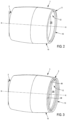
figure 1 est une vue en coupe d'une nacelle de turbomachine, - La
figure 2 est une vue en perspective d'un premier exemple de réalisation d'un ensemble pour turbomachine selon l'invention dans une première configuration, - La
figure 3 est une vue en perspective du premier exemple de réalisation d'un ensemble pour turbomachine illustré enfigure 1 dans une deuxième configuration, - La
figure 4 est une vue en coupe d'une partie d'un deuxième exemple de réalisation d'un ensemble pour turbomachine selon l'invention dans une première configuration, - La
figure 5 est une vue en coupe d'une partie d'un troisième exemple de réalisation d'un ensemble pour turbomachine selon l'invention dans une première configuration - La
figure 6 est une vue en coupe d'une partie du deuxième exemple de réalisation d'un ensemble pour turbomachine illustré enfigure 4 , dans une deuxième configuration, - La
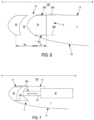
figure 7 est une vue en coupe d'une partie d'un quatrième exemple de réalisation d'un ensemble pour turbomachine selon l'invention dans une première configuration, - La
figure 8 est une vue en coupe d'une partie du quatrième exemple de réalisation d'un ensemble pour turbomachine illustré enfigure 7 dans une deuxième configuration, - La
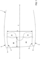
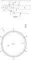
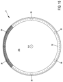
figure 9 est une vue de face d'un cinquième exemple de réalisation d'un ensemble pour turbomachine selon l'invention, - La
figure 10 est une vue en coupe d'une partie d'un sixième exemple de réalisation d'un ensemble pour turbomachine selon l'invention dans une deuxième configuration, - La
figure 11 est une vue en coupe d'une partie d'un septième exemple de réalisation d'un ensemble pour turbomachine selon l'invention dans une première configuration, - La
figure 12 est une vue en coupe d'une partie du septième exemple de réalisation d'un ensemble pour turbomachine illustré enfigure 11 dans une deuxième configuration, - La
figure 13 est une vue en perspective de côté d'un huitième exemple de réalisation d'un ensemble pour turbomachine selon l'invention, - La
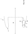
figure 14 est une vue en coupe d'un neuvième exemple de réalisation d'un ensemble pour turbomachine selon l'invention, - La
figure 15 est une vue de face du neuvième exemple de réalisation d'un ensemble pour turbomachine selon l'invention illustré enfigure 14 , - La
figure 16 est une vue en coupe d'un dixième exemple de réalisation d'un ensemble pour turbomachine selon l'invention, et - La
figure 17 est une vue de face du dixième exemple de réalisation d'un ensemble pour turbomachine selon l'invention illustré enfigure 14 .
- There
figure 1 is a sectional view of a turbomachine nacelle, - There
figure 2 is a perspective view of a first embodiment of a turbomachine assembly according to the invention in a first configuration, - There
Figure 3 is a perspective view of the first embodiment of an assembly for a turbomachine illustrated infigure 1 in a second configuration, - There
Figure 4 is a sectional view of a part of a second embodiment of an assembly for a turbomachine according to the invention in a first configuration, - There
figure 5 is a sectional view of a part of a third embodiment of an assembly for a turbomachine according to the invention in a first configuration - There
Figure 6 is a sectional view of part of the second embodiment of a turbomachine assembly illustrated inFigure 4 , in a second configuration, - There
figure 7 is a sectional view of part of a fourth embodiment of an assembly for a turbomachine according to the invention in a first configuration, - There
figure 8 is a sectional view of part of the fourth embodiment of a turbomachine assembly illustrated infigure 7 in a second configuration, - There
Figure 9 is a front view of a fifth embodiment of a turbomachine assembly according to the invention, - There
Figure 10 is a sectional view of a part of a sixth embodiment of an assembly for a turbomachine according to the invention in a second configuration, - There
Figure 11 is a sectional view of a part of a seventh embodiment of an assembly for a turbomachine according to the invention in a first configuration, - There
Figure 12 is a sectional view of part of the seventh embodiment of a turbomachine assembly illustrated inFigure 11 in a second configuration, - There
Figure 13 is a side perspective view of an eighth embodiment of an assembly for a turbomachine according to the invention, - There
Figure 14 is a sectional view of a ninth embodiment of an assembly for a turbomachine according to the invention, - There
Figure 15 is a front view of the ninth embodiment of an assembly for a turbomachine according to the invention illustrated inFigure 14 , - There
Figure 16 is a sectional view of a tenth embodiment of an assembly for a turbomachine according to the invention, and - There
Figure 17 is a front view of the tenth embodiment of an assembly for a turbomachine according to the invention illustrated inFigure 14 .
En référence aux
La nacelle 1 comprend en outre une lèvre d'entrée 10 définissant une entrée d'air 100 par laquelle de l'air peut être admis au sein de la turbomachine. La lèvre d'entrée 10 permet de joindre, à une extrémité amont de la nacelle 1, une paroi interne 12 de la nacelle 1, en contact avec le flux d'air admis au sein de la turbomachine, avec une paroi externe 14 de la nacelle 1, en contact avec l'air circulant autour de la turbomachine.The
Dans tout ce qui va suivre, on définit l'amont et l'aval par rapport au sens d'écoulement d'air au sein de la turbomachine. En outre, on définit par « axial » une direction sensiblement parallèle à l'axe longitudinal X-X, et par « radial » une direction sensiblement orthogonal audit axe longitudinal X-X.In everything that follows, we define the upstream and downstream in relation to the direction of air flow within the turbomachine. In addition, we define by “axial” a direction substantially parallel to the longitudinal axis XX, and by “radial” a direction substantially orthogonal to said longitudinal axis XX.
La nacelle 1 entoure généralement un corps moteur 2 de la turbomachine, à l'amont duquel une soufflante 20 s'étend. En fonctionnement, la soufflante 20 aspire le flux d'air admis par l'entrée d'air 100, et le propulse à l'intérieur du corps moteur 2. Comme visible sur la
Un dispositif de modification d'une géométrie de l'entrée d'air 3 grâce auquel la nacelle 1 peut présenter au moins deux configurations illustrées notamment en
Dans une première configuration, illustrée en
Dans une deuxième configuration, illustrée en
En tout état de cause, le dispositif de modification d'une géométrie de l'entrée d'air 3 permet d'améliorer la capacité de la nacelle1 à réduire la distorsion du flux d'air admis au niveau de l'entrée d'air 100, ce qui permet notamment d'améliorer le comportement aérodynamique de la soufflante 20.In any case, the device for modifying a geometry of the
Comme visible plus précisément sur les
- une première configuration, illustrée en
figures 2 ,4 ,5 ,7 et11 , où :- ∘ le premier bec 30 forme la lèvre d'entrée 10, et
- ∘ le deuxième bec 32 s'étend à l'intérieur de la
nacelle 1, et
- une deuxième configuration, illustrée en
figures 3 ,8 ,10 ,12 à 14 , et16 , où :- ∘ le premier bec 30 s'étend à distance de la lèvre d'entrée 10, et
- ∘ le deuxième bec 32 forme la lèvre d'entrée 10,
- a first configuration, illustrated in
figures 2 ,4 ,5 ,7 And11 , Or :- ∘ the
first nozzle 30 forms theinlet lip 10, and - ∘ the
second nozzle 32 extends inside thenacelle 1, and
- ∘ the
- a second configuration, illustrated in
figures 3 ,8 ,10 ,12 to 14 , And16 , Or :- ∘ the
first nozzle 30 extends at a distance from theinlet lip 10, and - ∘ the
second nozzle 32 forms theinlet lip 10,
- ∘ the
Dans la première configuration, le deuxième bec 32 demeure à l'intérieur de la nacelle 1, sans interaction avec l'écoulement d'air circulant autour de la lèvre d'entrée 10, c'est-à-dire de manière confinée.In the first configuration, the
Dans la deuxième configuration, le premier bec 30 et le deuxième bec 32 définissent un canal d'écoulement d'air 34 entre une surface aval du premier bec 30 et une surface amont du deuxième bec 32.In the second configuration, the
Ainsi, dans la première configuration, l'entrée d'air 100 présente une géométrie nominale, c'est-à-dire particulièrement adaptée à des conditions de vol de croisière, à vitesse élevée d'écoulement d'air, et, dans la deuxième configuration, la géométrie de l'entrée d'air 100 est modifiée de sorte à être particulièrement adaptée à des conditions de vol au décollage et/ou au niveau du sol, à vitesse plus faible d'écoulement d'air. La première configuration et la deuxième configuration du premier bec 30 et du deuxième bec 32 correspondent, respectivement, à la position escamotée et à la position déployée du dispositif de modification d'une géométrie de l'entrée d'air 3.Thus, in the first configuration, the
En référence aux
Avantageusement, comme visible sur la
De manière également avantageuse, comme visible sur les
Dans un mode de réalisation, il est prévu un système de dégivrage du premier bec 30 et/ou du deuxième bec 32. En effet, à haute altitude, le risque de givrage est particulièrement important au niveau de la lèvre d'entrée 10. Un tel système garantit donc le bon fonctionnement du dispositif de modification d'une géométrie de l'entrée d'air 3. Avantageusement, le système de dégivrage comprend un canal de circulation de fluide de dégivrage qui s'étend au moins en partie à l'intérieur d'une tige de guidage 36. La tige de guidage 36 peut donc être au moins partiellement creuse, de sorte à véhiculer le fluide de dégivrage, par exemple de l'air chaud. Ceci permet notamment d'assurer le dégivrage du premier bec 30 et/ou du deuxième bec 32 quelle que soit la configuration du dispositif de modification d'une géométrie de l'entrée d'air 3. A cet égard, un mode de réalisation où le premier bec 30 est monté fixe par rapport au deuxième bec 32, comme visible notamment sur la
En référence aux
Avantageusement, l'actionneur 38 est configuré pour mettre en mouvement la tige de guidage 36, de sorte à passer de la première configuration à la deuxième configuration, et vice-versa.Advantageously, the actuator 38 is configured to set the guide rod 36 in motion, so as to move from the first configuration to the second configuration, and vice versa.
En tout état de cause, en référence aux
L'actionneur 38 peut être pneumatique. Dans ce cas, il est possible de coupler le système de dégivrage de la nacelle 1, par exemple à air chaud, avec l'actionneur 38.The actuator 38 can be pneumatic. In this case, it is possible to couple the defrosting system of the
La présence d'un actionneur 38 pour assurer le déploiement et/ou le rangement du dispositif de modification d'une géométrie de l'entrée d'air 3 n'est cependant pas obligatoire, comme visible sur les
- à vitesse élevée d'écoulement d'air, la pression dynamique à l'infini amont de la turbomachine génère un effort axial vers l'aval qui repousse naturellement le dispositif de modification d'une géométrie de l'entrée d'air 3 dans sa position escamotée, ce qui correspond à la première configuration illustrée sur les
figures 4 ,7 et11 , et - à vitesse faible d'avancement de l'aéronef sur lequel la turbomachine est montée, et à débit d'air admis par la turbomachine élevé (e.g. au décollage), l'accélération de l'écoulement lors du contournement de la lèvre d'entrée 10 crée un champ de pression autour de ladite lèvre d'entrée 10 qui génère un effort axial dirigé vers l'amont; cet effort déploie naturellement le dispositif de modification d'une géométrie de l'entrée d'air 3, comme visible en
figure 6 , et le maintien en position déployée, ce qui correspond à la deuxième configuration illustrée sur lesfigures 8 ,10 ,12 à 14, et 16.
- at high air flow speed, the dynamic pressure at infinity upstream of the turbomachine generates an axial force towards the downstream which naturally pushes the device for modifying a geometry of the
air inlet 3 into its retracted position, which corresponds to the first configuration illustrated on thefigures 4 ,7 And11 , And - at low forward speed of the aircraft on which the turbomachine is mounted, and at high air flow admitted by the turbomachine (eg at takeoff), the acceleration of the flow when bypassing the
inlet lip 10 creates a pressure field around saidinlet lip 10 which generates an axial force directed upstream; this effort naturally deploys the device for modifying a geometry of theair inlet 3, as visible inFigure 6 , and maintaining the deployed position, which corresponds to the second configuration illustrated on thefigures 8 ,10 ,12 at 14, and 16.
Il est alors possible de prévoir, alternativement ou en complément de l'actionneur 38, un dispositif de verrouillage configuré pour immobiliser le dispositif de modification d'une géométrie de l'entrée d'air 3 dans la première configuration et/ou dans la deuxième configuration, le déploiement et le rangement pouvant par ailleurs être naturellement assurés par l'écoulement d'air à vitesse élevée et/ou à vitesse faible. Ainsi, le dispositif de modification d'une géométrie de l'entrée d'air 3 présente une robustesse importante, et il n'est plus nécessaire de prévoir des dispositifs de secours pour pallier une éventuelle défaillance de l'actionneur 38.It is then possible to provide, alternatively or in addition to the actuator 38, a locking device configured to immobilize the device for modifying a geometry of the
En référence à la
Comme visible sur la
- un premier rayon R1 qui correspond au rayon du col de l'entrée, c'est-à-dire à la distance séparant une surface de la paroi interne 12 de la
nacelle 1 qui est la plus proche de l'axe longitudinal X-X, dudit axe longitudinal X-X, - un deuxième rayon R2 qui correspond au rayon de fin de divergence de l'entrée d'air 100, c'est-à-dire à la distance séparant une surface de la paroi interne 12 de la
nacelle 1 qui est la plus éloignée de l'axe longitudinal X-X, dudit axe longitudinal X-X, et - une épaisseur e de lèvre d'entrée 10, qui correspond à la distance séparant la surface de la paroi interne 12 de la
nacelle 1 qui est la plus proche de l'axe longitudinal X-X d'une surface de la paroi externe 14 de lanacelle 1 la plus éloignée dudit axe longitudinal X-X.
- a first radius R1 which corresponds to the radius of the neck of the inlet, that is to say the distance separating a surface of the internal wall 12 of the
nacelle 1 which is closest to the longitudinal axis XX, of said longitudinal axis XX, - a second radius R2 which corresponds to the end radius of divergence of the
air inlet 100, that is to say the distance separating a surface of the internal wall 12 of thenacelle 1 which is furthest from the longitudinal axis XX, said longitudinal axis XX, and - a thickness e of
inlet lip 10, which corresponds to the distance separating the surface of the internal wall 12 of thenacelle 1 which is closest to the longitudinal axis XX from a surface of theexternal wall 14 of thenacelle 1 furthest from said longitudinal axis XX.
Comme visible sur la
De plus, le premier bec 30 définit un profil amont de premier bec C1. Ce profil amont de premier bec C1 forme une surface amont de premier bec 302, qui est tridimensionnelle de révolution autour de l'axe longitudinal X-X. Une coupe du profil amont de premier bec C1 dans le plan radial P forme alors une ligne géométrique reliant une ligne géométrique formée de la coupe, dans le plan radial P, de la face radiale interne 300 du premier bec 30 à une ligne géométrique formée de la coupe, dans le plan radial P, de la face radiale externe 301 du premier bec 30, en amont du premier bec 30. Cette ligne géométrique peut être définie par n'importe quelle courbe passant par la ligne géométrique formée de la coupe, dans le plan radial P, de la face radiale interne 300 du premier bec 30 et par ligne géométrique formée de la coupe, dans le plan radial P, de la face radiale externe 301 du premier bec 30, en amont du premier bec 30. Suivant la forme de la surface amont de premier bec 302, le profil amont de premier bec C1 peut présenter une forme de ligne géométrique différente dans un autre plan radial P', qui comprend également l'axe longitudinal X-X et qui est différent du plan radial P.In addition, the
En outre, le premier bec 30 définit un profil aval de premier bec C2. Ce profil aval de premier bec C2 forme une surface aval de premier bec 303, qui est tridimensionnelle de révolution autour de l'axe longitudinal X-X. Une coupe du profil aval de premier bec C2 dans le plan radial P forme alors une ligne géométrique reliant une ligne géométrique formée de la coupe, dans le plan radial P, de la face radiale interne 300 du premier bec 30 à une ligne géométrique formée de la coupe, dans le plan radial P, de la face radiale externe 301 du premier bec 30, en aval du premier bec 30. Cette ligne géométrique peut être définie par n'importe quelle courbe passant par la ligne géométrique formée de la coupe, dans le plan radial P, de la face radiale interne 300 du premier bec 30 et par la ligne géométrique formée de la coupe, dans le plan radial P, de la face radiale externe 301 du premier bec 30, en aval du premier bec 30. Suivant la forme de la surface aval de premier bec 303, le profil aval de premier bec C2 peut présenter une forme différente de ligne géométrique dans un autre plan radial P', qui comprend également l'axe longitudinal X-X et qui est différent du plan radial P.In addition, the
Par ailleurs, le premier bec 30 définit une envergure radiale ε correspondant à la différence entre le troisième rayon R3 et le quatrième rayon R4, c'est-à-dire à la distance séparant la face radiale interne 300 du premier bec 30 de sa face radiale externe 301. L'envergure radiale ε est limitée par l'épaisseur e de la lèvre d'entrée 10, pour pouvoir facilement déployer et ranger le dispositif de modification d'une géométrie de l'entrée d'air 3. De préférence, un rapport de l'envergure radiale ε de premier bec 30 sur l'épaisseur e de lèvre d'entrée 10 est compris entre 0,4 et 0,6. En tout état de cause, la face radiale interne 300 du premier bec 30 s'étend le plus proche possible de l'axe longitudinal X-X, c'est-à-dire substantiellement dans le même plan que la surface de la paroi interne 12 de la nacelle 1 qui est la plus éloignée de l'axe longitudinal X-X, comme visible sur la
En outre, le premier bec 30 définit une longueur de face radiale interne de premier bec H1, correspondant à la distance séparant l'extrémité radiale interne du profil amont de premier bec C1 de l'extrémité radiale interne d'une surface aval du premier bec 30. Comme visible sur la
De plus, le premier bec 30 définit une longueur de face radiale externe de premier bec H2, correspondant à la distance séparant l'extrémité radiale externe du profil amont de premier bec C1 de l'extrémité radiale externe d'une surface aval du premier bec 30. Comme visible sur la
Enfin, en référence aux
Comme également visible sur la
En tout état de cause, le profil amont de deuxième bec C3 présente, dans la deuxième configuration, une continuité tangentielle avec un profil de la nacelle 1 défini dans le plan radial P. Plus précisément, comme visible sur la
Dans un mode de réalisation privilégié, par exemple illustré sur la
Toujours en référence à la
- une longueur axiale interne δ1 définie comme la distance séparant l'extrémité aval de la face radiale interne de
premier bec 300 de l'extrémité amont de la face radiale interne de deuxième bec 320, et - une longueur axiale externe δ2 définie comme la distance séparant l'extrémité aval de la face radiale externe de
premier bec 301 de l'extrémité amont de la face radiale externe de deuxième bec 321.
- an internal axial length δ1 defined as the distance separating the downstream end of the internal radial face of
first nozzle 300 from the upstream end of the internal radial face ofsecond nozzle 320, and - an external axial length δ2 defined as the distance separating the downstream end of the external radial face of
first nozzle 301 from the upstream end of the external radial face ofsecond nozzle 321.
Dans une configuration avantageuse du dispositif de modification d'une géométrie de l'entrée d'air 3, la longueur axiale interne δ1 du canal d'écoulement d'air 34 est inférieure à la longueur axiale externe δ2 du canal d'écoulement d'air 34. Ceci permet de définir une géométrie convergente de canal d'écoulement d'air 34, comme visible sur la
En outre, dans un mode de réalisation où le premier bec 30 est monté fixe par rapport au deuxième bec 32, comme visible sur la
Par ailleurs, le dispositif de modification d'une géométrie de l'entrée d'air 3 présente, quelle que soit sa position, une envergure axiale δe définie comme la somme de :
- la longueur de face radiale interne de premier bec H1 et de la longueur axiale interne de canal d'écoulement δ1, ou
- la longueur de face radiale externe de premier bec H2 et de la longueur axiale externe de canal d'écoulement δ2.
- the internal radial face length of first nozzle H1 and the internal axial length of flow channel δ1, or
- the external radial face length of first nozzle H2 and the external axial length of flow channel δ2.
De là, le dispositif de modification d'une géométrie de l'entrée d'air 3 définit une envergure axiale maximale δ comme la plus grande de la distance séparant l'extrémité radiale externe du profil amont de premier bec C1 de l'extrémité radiale externe du rebord amont de paroi interne 12 de la nacelle 1, et de la distance séparant l'extrémité radiale interne du profil amont de premier bec C1 de l'extrémité radiale interne du rebord amont de paroi interne 12 de la nacelle 1, lorsque le dispositif de modification d'une géométrie de l'entrée d'air 3 est en position déployée. En d'autres termes, l'envergue axiale maximale δ correspond à l'envergure axiale δe du dispositif de modification d'une géométrie de l'entrée d'air 3 lorsqu'il se trouve en position déployée.From there, the device for modifying a geometry of the
L'espace disponible pour l'extension du dispositif de modification d'une géométrie de l'entrée d'air 3 est limitée au sein de la nacelle 1, lorsque ledit dispositif de modification d'une géométrie de l'entrée d'air 3 est dans la première configuration, c'est-à-dire en position escamotée. Ainsi, la longueur axiale δi des rails 380 est de préférence égale à l'envergue axiale δe en position escamotée, et en tout état de cause n'est pas inférieure à l'envergue axiale δe.The space available for the extension of the device for modifying a geometry of the
En tout état de cause, la longueur axiale interne de canal d'écoulement d'air δ1 et la longueur axiale externe de canal d'écoulement d'air δ2 sont chacune inférieure à l'envergure axiale δe du dispositif de modification d'une géométrie de l'entrée d'air 3. En outre, elles sont chacune avantageusement non nulles, pour garantir l'existence du canal d'écoulement d'air 34. Par ailleurs, dans un mode de réalisation où le premier bec 30 et le deuxième bec 32 peuvent être mis en mouvement axial indépendamment l'un de l'autre, la longueur axiale interne de canal d'écoulement d'air δ1 et la longueur axiale externe de canal d'écoulement d'air δ2 peuvent prendre une valeur minimale qui dépend du point de contact entre le premier bec 30 et le deuxième bec 32. Ceci est notamment visible sur la
Le canal d'écoulement d'air 34 présente donc, dans le plan radial P :
- un profil amont, correspondant au profil aval de premier bec C2, et
- un profil aval, correspondant au profil amont de deuxième bec C3.
- an upstream profile, corresponding to the downstream profile of first nozzle C2, and
- a downstream profile, corresponding to the upstream profile of second nozzle C3.
Avantageusement, le canal d'écoulement d'air 34 peut présenter une géométrie différente autour de l'axe longitudinal X-X. En d'autres termes, comme visible notamment sur les
- dans un premier plan radial P1 :
- ∘ un premier profil amont, correspondant à un premier profil aval de premier bec C21, et
- ∘ un premier profil aval, correspondant à un premier profil amont de deuxième bec C31, et
- dans un deuxième plan radial P2 :
- ∘ un deuxième profil amont, correspondant à un deuxième profil aval de premier bec C22, et
- ∘ un deuxième profil aval, correspondant à un deuxième profil amont de deuxième bec C32.
- in a first radial plane P1:
- ∘ a first upstream profile, corresponding to a first downstream profile of first nozzle C21, and
- ∘ a first downstream profile, corresponding to a first upstream profile of second nozzle C31, and
- in a second radial plane P2:
- ∘ a second upstream profile, corresponding to a second downstream profile of first nozzle C22, and
- ∘ a second downstream profile, corresponding to a second upstream profile of second nozzle C32.
Plus précisément, le deuxième profil amont de deuxième bec C32 étant différent du premier profil amont de deuxième bec C31, et/ou le deuxième profil aval de premier bec C22 étant différent du premier profil aval de premier bec C21, comme visible sur les
Les
Ceci permet d'optimiser localement l'effet aérodynamique de la modification de la géométrie de l'entrée d'air 100. Cette possibilité est notamment avantageuse lorsque la nacelle 1 n'est pas axisymétrique, comme visible sur les
De cette manière, il est possible de définir un degré de convergence géométrique du canal d'écoulement d'air34. Plus précisément, en supposant que la surface radiale interne A1 et la surface radiale externe A2 du canal d'écoulement d'air 34 sont des génératrices de cylindre à base circulaire, on peut définir un taux de convergence τ du canal d'écoulement d'air 34 comme le rapport de la surface radiale interne A1 du canal d'écoulement d'air 34 sur la surface radiale externe A2 du canal d'écoulement d'air 34 : 
Dans la mesure où le rapport du troisième rayon R3 sur le quatrième rayon R4 est toujours supérieur à 1, le canal d'écoulement d'air 34 est naturellement convergent. En revanche, le rapport de la longueur axiale interne δ1 du canal d'écoulement d'air 34 sur sa longueur axiale externe δ2 permet d'influer sur le taux de convergence τ. En effet, ce rapport vaut : 
Ainsi, la convergence peut être définie par le choix respectif de la longueur de face radiale interne de premier bec H1 et de la longueur de face radiale externe de premier bec H2, qui sont par ailleurs chacune limitées par l'envergure axiale δ du dispositif de modification d'une géométrie de l'entrée d'air 3.Thus, the convergence can be defined by the respective choice of the length of the internal radial face of the first nozzle H1 and the length of the external radial face of the first nozzle H2, which are also each limited by the axial span δ of the device of modification of a geometry of the
Le canal d'écoulement d'air 34 permet, dans la deuxième configuration, de fournir une modification supplémentaire de quantité de mouvement au sein du fluide admis par l'entrée d'air 100. Cette modification peut consister en une accélération ou en une décélération du fluide admis. A basse vitesse d'écoulement, typiquement dans le domaine subsonique, une accélération est généralement recherchée, et il faut alors que le taux de convergence τ soit inférieur à 1, c'est-à-dire que la section longitudinale de canal d'écoulement d'air 34 soit convergente. En tout état de cause, , la structure du dispositif de modification d'une géométrie de l'entrée d'air 3 permet à la fois des taux de convergence τ importants, c'est-à-dire proche de 0, mais aussi très faibles, c'est-à-dire proche de 1, voire même des divergences, c'est-à-dire lorsque le taux de convergence τ est supérieur à 1.The air flow channel 34 makes it possible, in the second configuration, to provide an additional modification of the momentum within the fluid admitted by the
Dans un mode de réalisation où une première section longitudinale du canal d'écoulement d'air 34, dans un premier plan radial P1, est différente d'une deuxième section longitudinale, dans un deuxième plan radial P2, l'envergure axiale δ du dispositif de modification d'une géométrie de l'entrée d'air 3 est la même dans le premier plan P1 et dans le deuxième plan P2, comme visible par exemple sur les
Comme visible sur les
Cependant, les différentes portions angulaires de premier bec 30 et/ou de deuxième bec 32 peuvent être déplacées entre la première configuration et la deuxième configuration, et vice-versa, indépendamment les unes des autres. En d'autres termes, le dispositif de modification d'une géométrie de l'entrée d'air 3 peut comprendre une pluralité de premiers becs 30 reliés à une pluralité de deuxièmes becs 32, chacun s'étendant selon une portion angulaire autour de l'axe longitudinal X-X, et chacun étant mobiles en translation entre une première configuration et une deuxième configuration. Ainsi, un premier bec 30 et un deuxième bec 32 peuvent être dans la première configuration, tandis qu'un autre premier bec 30 et un autre deuxième bec 32 sont dans la deuxième configuration. Ceci garantit une modularité d'utilisation du dispositif de modification d'une géométrie de l'entrée d'air 3, suivant les différents écoulements admis au sein de l'entrée d'air 100. Avantageusement, la pluralité de premiers becs 30 et la pluralité de deuxièmes becs peuvent également présenter des profils amont C1, C3 et aval C2 qui sont différents les uns des autres.However, the different angular portions of
En référence aux
Par conséquent, dans un premier mode de réalisation illustré sur les
Dans un deuxième mode de réalisation, illustré sur les
Claims (12)
- An assembly for a gas turbine engine comprising:- a nacelle (1) having a longitudinal axis (X-X) and comprising an intake lip (10) defining an air intake (100), and- a device for modifying the geometry of the air intake (3), said device (3) comprising:- a first slat (30), and- a second slat (32),the first slat (30) and the second slat (32) being mobile in translation according to the longitudinal axis (X-X) relative to the nacelle (1) between:- a first configuration where the first slat (30) forms the intake lip (10) and the second slat (32) extends inside the nacelle (1), and- a second configuration where the first slat (30) extends at a distance from the intake lip (10), and the second slat (32) forms the intake lip (10) so as to define an airflow channel (34) between a downstream surface of the first slat (30) and an upstream surface of the second slat (32),The assembly being characterized in that the first slat (30) has:- in a first radial plane (P1) relative to the longitudinal axis (X-X), a first downstream profile of the first slat (C21), and- in a second radial plane (P2) relative to the longitudinal axis (X-X), a second downstream profile of the first slat (C22),the second downstream profile of the first slat (C22) being different to the first downstream profile of the first slat (C21), such that the airflow channel (34) has, in the first radial plane (P1), a first longitudinal section, and in the second radial plane (P2), a second longitudinal section, the second longitudinal section being different to the first longitudinal section.
- The assembly for a gas turbine engine according to claim 1, wherein the second slat (32) has, in a radial plane (P) relative to the longitudinal axis (X-X), an upstream profile of the second slat (C3), the upstream profile of the second slat (C3) having, in the second configuration, a tangential continuity with a profile of the nacelle (1) defined in the radial plane (P).
- The assembly for a gas turbine engine according to any one of claims 1 and 2, wherein the first slat (30) has, in a radial plane (P) relative to the longitudinal axis (X-X), an upstream profile of the first slat (C1), and the second slat (32) has, in the radial plane (P), an upstream profile of the second slat (C3), the upstream profile of the second slat (C3) being identical to the upstream profile of the first slat (C1).
- The assembly for a gas turbine engine according to any one of claims 1 to 3, wherein the second slat (32) has:- in a first radial plane (P1) relative to the longitudinal axis (X-X), a first upstream profile of the second slat (C31), and- in a second radial plane (P2) relative to the longitudinal axis (X-X), a second upstream profile of the second slat (C32),- the second upstream profile of the second slat (C32) being different to the first upstream profile of the second slat (C31), such that the airflow channel (34) has, in the first radial plane (P1), a first longitudinal section, and in the second radial plane (P2), a second longitudinal section, the second longitudinal section being different to the first longitudinal section.
- The assembly for a gas turbine engine according to any one of claims 1 to 4, wherein, over at least one angular portion of the device for modifying the geometry of the air intake (3), the first slat (30) and the second slat (32) are connected so as to form a single slat (33), also mobile in translation according to the longitudinal axis (X-X) relative to the nacelle (1).
- The assembly for a gas turbine engine according to any one of claims 1 to 5, wherein the first slat (30) and the second slat (32) extend over a first angular portion of the nacelle (1), a second angular portion of the nacelle (2) being bordered by a fixed part of the air intake lip (10).
- The assembly for a gas turbine engine according to any one of claims 1 to 6, wherein the device for modifying the geometry of the air intake (3) comprises a guide rod (36) extending parallel to the longitudinal axis (X-X), and connecting the first slat (30) to the second slat (32) such that, over at least one angular portion of the device for modifying the geometry of the air intake (3), the first slat (30) is mounted fixed relative to the second slat (32).
- The assembly for a gas turbine engine according to any one of claims 1 to 7, wherein the device for modifying the geometry of the air intake (3) comprises a guide rod (36) extending parallel to the longitudinal axis (X-X), the guide rod (36) being telescopic so that over at least one angular portion of the device for modifying the geometry of the air intake (3), the movement of the first slat (30) is independent of the movement of the second slat (32).
- The assembly for a gas turbine engine according to any one of claims 7 and 8, comprising an anti-icing system of the first slat (30) and/or of the second slat (32), comprising an anti-icing fluid circulation channel extending at least in part inside the guide rod (36).
- The assembly for a gas turbine engine according to any one of claims 1 to 9, wherein the device for modifying the geometry of the air intake (3) also comprises an actuator (36) lodged in the nacelle (1) and configured to set in motion the first slat (30) and the second slat (32) between the first configuration and the second configuration.
- The assembly for a gas turbine engine according to any one of claims 1 to 10, wherein the nacelle (1) has a non-axisymmetric shape.
- A gas turbine engine according to any one of claims 1 to 11.
Applications Claiming Priority (2)
| Application Number | Priority Date | Filing Date | Title |
|---|---|---|---|
| FR1911490A FR3101854B1 (en) | 2019-10-15 | 2019-10-15 | TURBOMACHINE NACELLE |
| PCT/FR2020/051841 WO2021074535A1 (en) | 2019-10-15 | 2020-10-15 | Assembly for turbomachine |
Publications (2)
| Publication Number | Publication Date |
|---|---|
| EP4045397A1 EP4045397A1 (en) | 2022-08-24 |
| EP4045397B1 true EP4045397B1 (en) | 2024-07-31 |
Family
ID=69190963
Family Applications (1)
| Application Number | Title | Priority Date | Filing Date |
|---|---|---|---|
| EP20799779.2A Active EP4045397B1 (en) | 2019-10-15 | 2020-10-15 | Assembly for turbomachine |
Country Status (5)
| Country | Link |
|---|---|
| US (1) | US11913378B2 (en) |
| EP (1) | EP4045397B1 (en) |
| CN (1) | CN114981162B (en) |
| FR (1) | FR3101854B1 (en) |
| WO (1) | WO2021074535A1 (en) |
Families Citing this family (4)
| Publication number | Priority date | Publication date | Assignee | Title |
|---|---|---|---|---|
| US10221764B2 (en) * | 2014-08-19 | 2019-03-05 | Pratt & Whitney Canada Corp. | Variable geometry inlet system |
| US12435666B1 (en) * | 2024-10-09 | 2025-10-07 | General Electric Company | Turbine engine having a variable engine intake system |
| US12529335B1 (en) | 2024-10-09 | 2026-01-20 | General Electric Company | Turbine engine having a variable engine intake system |
| US12442333B1 (en) | 2024-10-09 | 2025-10-14 | General Electric Company | Turbine engine having a variable engine intake system |
Citations (2)
| Publication number | Priority date | Publication date | Assignee | Title |
|---|---|---|---|---|
| DE2318380B2 (en) * | 1973-04-12 | 1976-10-07 | Dornier Gmbh, 7990 Friedrichshafen | AIR INLET FOR AIRPLANE ENGINES |
| US20180371996A1 (en) * | 2017-06-26 | 2018-12-27 | The Boeing Company | Translating turning vanes for a nacelle inet |
Family Cites Families (12)
| Publication number | Priority date | Publication date | Assignee | Title |
|---|---|---|---|---|
| US5014933A (en) * | 1989-04-27 | 1991-05-14 | The Boeing Company | Translating lip aircraft cowling structure adapted for noise reduction |
| US5000399A (en) * | 1990-02-23 | 1991-03-19 | General Electric Company | Variable contour annular air inlet for an aircraft engine nacelle |
| DE4009223A1 (en) * | 1990-03-22 | 1991-09-26 | Mtu Muenchen Gmbh | PROPFAN TURBO ENGINE |
| US7131612B2 (en) * | 2003-07-29 | 2006-11-07 | Pratt & Whitney Canada Corp. | Nacelle inlet lip anti-icing with engine oil |
| FR2906568B1 (en) * | 2006-10-02 | 2012-01-06 | Aircelle Sa | DEPOSITABLE AIR INTAKE STRUCTURE FOR TURBOJET NACELLE. |
| FR2927061B1 (en) * | 2008-02-01 | 2010-02-12 | Aircelle Sa | LATCHING SYSTEM FOR AIR INTAKE STRUCTURE OF A TURBOJET NACELLE |
| US8181905B2 (en) * | 2008-12-17 | 2012-05-22 | Rohr, Inc. | Aircraft engine nacelle with translating inlet cowl |
| FR2942457B1 (en) * | 2009-02-24 | 2011-04-22 | Snecma | TURBOREACTOR NACELLE WITH REMOVABLE AIR INTAKE STRUCTURE |
| US7871455B1 (en) * | 2009-06-19 | 2011-01-18 | Vintage Capital Group, Llc | Jet engine protection system |
| US8366057B2 (en) * | 2009-07-28 | 2013-02-05 | University Of Kansas | Method and apparatus for pressure adaptive morphing structure |
| FR2975972B1 (en) * | 2011-06-01 | 2013-11-22 | Aircelle Sa | TURBOREACTOR NACELLE AIR INTAKE STRUCTURE |
| DE102011103163A1 (en) * | 2011-06-01 | 2012-12-06 | Rolls-Royce Deutschland Ltd & Co Kg | Gas turbine engine with telescopic air intake of the engine cowling |
-
2019
- 2019-10-15 FR FR1911490A patent/FR3101854B1/en active Active
-
2020
- 2020-10-15 WO PCT/FR2020/051841 patent/WO2021074535A1/en not_active Ceased
- 2020-10-15 EP EP20799779.2A patent/EP4045397B1/en active Active
- 2020-10-15 CN CN202080078192.1A patent/CN114981162B/en active Active
- 2020-10-15 US US17/768,933 patent/US11913378B2/en active Active
Patent Citations (2)
| Publication number | Priority date | Publication date | Assignee | Title |
|---|---|---|---|---|
| DE2318380B2 (en) * | 1973-04-12 | 1976-10-07 | Dornier Gmbh, 7990 Friedrichshafen | AIR INLET FOR AIRPLANE ENGINES |
| US20180371996A1 (en) * | 2017-06-26 | 2018-12-27 | The Boeing Company | Translating turning vanes for a nacelle inet |
Also Published As
| Publication number | Publication date |
|---|---|
| CN114981162B (en) | 2026-02-13 |
| US20230349323A1 (en) | 2023-11-02 |
| FR3101854A1 (en) | 2021-04-16 |
| CN114981162A (en) | 2022-08-30 |
| WO2021074535A1 (en) | 2021-04-22 |
| US11913378B2 (en) | 2024-02-27 |
| EP4045397A1 (en) | 2022-08-24 |
| FR3101854B1 (en) | 2024-05-31 |
Similar Documents
| Publication | Publication Date | Title |
|---|---|---|
| FR3133367A1 (en) | AERONAUTICAL PROPELLER | |
| EP4045397A1 (en) | Assembly for turbomachine | |
| FR3078098A1 (en) | STRUCTURE WITH INCLINED SERRATION PROFILE | |
| CA2169874C (en) | Downstream air flaps thrust reverser for turbojet | |
| WO2016132073A1 (en) | Aircraft propulsion unit comprising an unducted-fan turbine engine and an attachment pylon | |
| FR3082230A1 (en) | NON-HULL ROTOR AIRCRAFT ENGINE WITH ADAPTATION OF STATOR BLADES | |
| FR2933953A1 (en) | VERTICAL PURPOSE AIRPLANE WITH VARIABLE SURFACE | |
| FR2938502A1 (en) | TURBOMACHINE COMPRISING A NON-CARNEY PROPELLER EQUIPPED WITH AIR GUIDING MEANS | |
| CA2743009C (en) | Air intake for an aeroplane engine with unducted propellers | |
| FR3021706A1 (en) | AIRCRAFT TURBOPROPULSOR COMPRISING TWO COAXIAL PROPELLERS. | |
| FR3027065A1 (en) | DEPLOYABLE GRID WITH FINS FOR AN AIRCRAFT TURBOMACHINE PUSH INVERSION SYSTEM | |
| EP4077880B1 (en) | Module for turbomachine | |
| EP3956226B1 (en) | Process for using an air input of a turboreactor nacelle comprising an air input lip which comprises a portion which can be moved to promote a thrust inversion phase | |
| FR3095194A1 (en) | Turbojet nacelle air inlet comprising a deflection device to promote a thrust reversal phase | |
| EP4716798A1 (en) | Thrust reverser comprising at least one deployable deflecting membrane | |
| EP4716797A1 (en) | Thrust reverser comprising at least one deployable deflecting membrane | |
| EP4025789B1 (en) | Polyspherical hub of a turbomachine for adjustable blades | |
| FR3052191B1 (en) | INVERSION OF PUSH IN A TURBOMACHINE WITH VARIABLE CALIBRATION BLOWER | |
| FR3079211A1 (en) | PROPELLANT AIRCRAFT ASSEMBLY COMPRISING TWO ADJACENT ENGINES, WHOSE OUTLETS HOLES HAVE A RIGHT PORTION CLOSE TO A MEDIAN PLAN OF THE PROPULSIVE ASSEMBLY | |
| WO2023026014A1 (en) | Reverser with movable cascades for an aircraft propulsion assembly, comprising a system for limiting the buckling of an actuator of the reverser | |
| WO2021136898A1 (en) | Thrust reverser comprising doors forming an upward air deflection opening in the open position | |
| EP4240650B1 (en) | Nacelle air intake for an aircraft propulsion assembly to promote a thrust reversal phase | |
| WO2021140053A1 (en) | Nozzle with variable outlet cross-section for rocket engine and rocket engine comprising such a nozzle | |
| EP4100638B1 (en) | Air outlet for an aircraft turbojet engine nacelle comprising a straightening device for supporting a reverse thrust phase | |
| FR2477100A1 (en) | AIR DELIVERY SYSTEM FOR TURBOCHARGED ENGINE |
Legal Events
| Date | Code | Title | Description |
|---|---|---|---|
| STAA | Information on the status of an ep patent application or granted ep patent |
Free format text: STATUS: UNKNOWN |
|
| STAA | Information on the status of an ep patent application or granted ep patent |
Free format text: STATUS: THE INTERNATIONAL PUBLICATION HAS BEEN MADE |
|
| PUAI | Public reference made under article 153(3) epc to a published international application that has entered the european phase |
Free format text: ORIGINAL CODE: 0009012 |
|
| STAA | Information on the status of an ep patent application or granted ep patent |
Free format text: STATUS: REQUEST FOR EXAMINATION WAS MADE |
|
| 17P | Request for examination filed |
Effective date: 20220511 |
|
| AK | Designated contracting states |
Kind code of ref document: A1 Designated state(s): AL AT BE BG CH CY CZ DE DK EE ES FI FR GB GR HR HU IE IS IT LI LT LU LV MC MK MT NL NO PL PT RO RS SE SI SK SM TR |
|
| DAV | Request for validation of the european patent (deleted) | ||
| DAX | Request for extension of the european patent (deleted) | ||
| GRAP | Despatch of communication of intention to grant a patent |
Free format text: ORIGINAL CODE: EPIDOSNIGR1 |
|
| STAA | Information on the status of an ep patent application or granted ep patent |
Free format text: STATUS: GRANT OF PATENT IS INTENDED |
|
| GRAJ | Information related to disapproval of communication of intention to grant by the applicant or resumption of examination proceedings by the epo deleted |
Free format text: ORIGINAL CODE: EPIDOSDIGR1 |
|
| STAA | Information on the status of an ep patent application or granted ep patent |
Free format text: STATUS: REQUEST FOR EXAMINATION WAS MADE |
|
| INTG | Intention to grant announced |
Effective date: 20240208 |
|
| GRAP | Despatch of communication of intention to grant a patent |
Free format text: ORIGINAL CODE: EPIDOSNIGR1 |
|
| STAA | Information on the status of an ep patent application or granted ep patent |
Free format text: STATUS: GRANT OF PATENT IS INTENDED |
|
| INTC | Intention to grant announced (deleted) | ||
| INTG | Intention to grant announced |
Effective date: 20240405 |
|
| GRAS | Grant fee paid |
Free format text: ORIGINAL CODE: EPIDOSNIGR3 |
|
| GRAA | (expected) grant |
Free format text: ORIGINAL CODE: 0009210 |
|
| STAA | Information on the status of an ep patent application or granted ep patent |
Free format text: STATUS: THE PATENT HAS BEEN GRANTED |
|
| AK | Designated contracting states |
Kind code of ref document: B1 Designated state(s): AL AT BE BG CH CY CZ DE DK EE ES FI FR GB GR HR HU IE IS IT LI LT LU LV MC MK MT NL NO PL PT RO RS SE SI SK SM TR |
|
| REG | Reference to a national code |
Ref country code: CH Ref legal event code: EP Ref country code: GB Ref legal event code: FG4D Free format text: NOT ENGLISH |
|
| REG | Reference to a national code |
Ref country code: DE Ref legal event code: R096 Ref document number: 602020034958 Country of ref document: DE |
|
| REG | Reference to a national code |
Ref country code: IE Ref legal event code: FG4D Free format text: LANGUAGE OF EP DOCUMENT: FRENCH |
|
| REG | Reference to a national code |
Ref country code: LT Ref legal event code: MG9D |
|
| REG | Reference to a national code |
Ref country code: NL Ref legal event code: MP Effective date: 20240731 |
|
| PG25 | Lapsed in a contracting state [announced via postgrant information from national office to epo] |
Ref country code: PT Free format text: LAPSE BECAUSE OF FAILURE TO SUBMIT A TRANSLATION OF THE DESCRIPTION OR TO PAY THE FEE WITHIN THE PRESCRIBED TIME-LIMIT Effective date: 20241202 |
|
| REG | Reference to a national code |
Ref country code: AT Ref legal event code: MK05 Ref document number: 1708245 Country of ref document: AT Kind code of ref document: T Effective date: 20240731 |
|
| PG25 | Lapsed in a contracting state [announced via postgrant information from national office to epo] |
Ref country code: PT Free format text: LAPSE BECAUSE OF FAILURE TO SUBMIT A TRANSLATION OF THE DESCRIPTION OR TO PAY THE FEE WITHIN THE PRESCRIBED TIME-LIMIT Effective date: 20241202 |
|
| PG25 | Lapsed in a contracting state [announced via postgrant information from national office to epo] |
Ref country code: NO Free format text: LAPSE BECAUSE OF FAILURE TO SUBMIT A TRANSLATION OF THE DESCRIPTION OR TO PAY THE FEE WITHIN THE PRESCRIBED TIME-LIMIT Effective date: 20241031 |
|
| PG25 | Lapsed in a contracting state [announced via postgrant information from national office to epo] |
Ref country code: FI Free format text: LAPSE BECAUSE OF FAILURE TO SUBMIT A TRANSLATION OF THE DESCRIPTION OR TO PAY THE FEE WITHIN THE PRESCRIBED TIME-LIMIT Effective date: 20240731 Ref country code: NL Free format text: LAPSE BECAUSE OF FAILURE TO SUBMIT A TRANSLATION OF THE DESCRIPTION OR TO PAY THE FEE WITHIN THE PRESCRIBED TIME-LIMIT Effective date: 20240731 Ref country code: PL Free format text: LAPSE BECAUSE OF FAILURE TO SUBMIT A TRANSLATION OF THE DESCRIPTION OR TO PAY THE FEE WITHIN THE PRESCRIBED TIME-LIMIT Effective date: 20240731 Ref country code: GR Free format text: LAPSE BECAUSE OF FAILURE TO SUBMIT A TRANSLATION OF THE DESCRIPTION OR TO PAY THE FEE WITHIN THE PRESCRIBED TIME-LIMIT Effective date: 20241101 |
|
| PG25 | Lapsed in a contracting state [announced via postgrant information from national office to epo] |
Ref country code: BG Free format text: LAPSE BECAUSE OF FAILURE TO SUBMIT A TRANSLATION OF THE DESCRIPTION OR TO PAY THE FEE WITHIN THE PRESCRIBED TIME-LIMIT Effective date: 20240731 |
|
| PG25 | Lapsed in a contracting state [announced via postgrant information from national office to epo] |
Ref country code: LV Free format text: LAPSE BECAUSE OF FAILURE TO SUBMIT A TRANSLATION OF THE DESCRIPTION OR TO PAY THE FEE WITHIN THE PRESCRIBED TIME-LIMIT Effective date: 20240731 |
|
| PG25 | Lapsed in a contracting state [announced via postgrant information from national office to epo] |
Ref country code: AT Free format text: LAPSE BECAUSE OF FAILURE TO SUBMIT A TRANSLATION OF THE DESCRIPTION OR TO PAY THE FEE WITHIN THE PRESCRIBED TIME-LIMIT Effective date: 20240731 Ref country code: IS Free format text: LAPSE BECAUSE OF FAILURE TO SUBMIT A TRANSLATION OF THE DESCRIPTION OR TO PAY THE FEE WITHIN THE PRESCRIBED TIME-LIMIT Effective date: 20241130 |
|
| PG25 | Lapsed in a contracting state [announced via postgrant information from national office to epo] |
Ref country code: HR Free format text: LAPSE BECAUSE OF FAILURE TO SUBMIT A TRANSLATION OF THE DESCRIPTION OR TO PAY THE FEE WITHIN THE PRESCRIBED TIME-LIMIT Effective date: 20240731 |
|
| PG25 | Lapsed in a contracting state [announced via postgrant information from national office to epo] |
Ref country code: RS Free format text: LAPSE BECAUSE OF FAILURE TO SUBMIT A TRANSLATION OF THE DESCRIPTION OR TO PAY THE FEE WITHIN THE PRESCRIBED TIME-LIMIT Effective date: 20241031 Ref country code: ES Free format text: LAPSE BECAUSE OF FAILURE TO SUBMIT A TRANSLATION OF THE DESCRIPTION OR TO PAY THE FEE WITHIN THE PRESCRIBED TIME-LIMIT Effective date: 20240731 |
|
| PG25 | Lapsed in a contracting state [announced via postgrant information from national office to epo] |
Ref country code: RS Free format text: LAPSE BECAUSE OF FAILURE TO SUBMIT A TRANSLATION OF THE DESCRIPTION OR TO PAY THE FEE WITHIN THE PRESCRIBED TIME-LIMIT Effective date: 20241031 Ref country code: PL Free format text: LAPSE BECAUSE OF FAILURE TO SUBMIT A TRANSLATION OF THE DESCRIPTION OR TO PAY THE FEE WITHIN THE PRESCRIBED TIME-LIMIT Effective date: 20240731 Ref country code: NO Free format text: LAPSE BECAUSE OF FAILURE TO SUBMIT A TRANSLATION OF THE DESCRIPTION OR TO PAY THE FEE WITHIN THE PRESCRIBED TIME-LIMIT Effective date: 20241031 Ref country code: NL Free format text: LAPSE BECAUSE OF FAILURE TO SUBMIT A TRANSLATION OF THE DESCRIPTION OR TO PAY THE FEE WITHIN THE PRESCRIBED TIME-LIMIT Effective date: 20240731 Ref country code: LV Free format text: LAPSE BECAUSE OF FAILURE TO SUBMIT A TRANSLATION OF THE DESCRIPTION OR TO PAY THE FEE WITHIN THE PRESCRIBED TIME-LIMIT Effective date: 20240731 Ref country code: IS Free format text: LAPSE BECAUSE OF FAILURE TO SUBMIT A TRANSLATION OF THE DESCRIPTION OR TO PAY THE FEE WITHIN THE PRESCRIBED TIME-LIMIT Effective date: 20241130 Ref country code: HR Free format text: LAPSE BECAUSE OF FAILURE TO SUBMIT A TRANSLATION OF THE DESCRIPTION OR TO PAY THE FEE WITHIN THE PRESCRIBED TIME-LIMIT Effective date: 20240731 Ref country code: GR Free format text: LAPSE BECAUSE OF FAILURE TO SUBMIT A TRANSLATION OF THE DESCRIPTION OR TO PAY THE FEE WITHIN THE PRESCRIBED TIME-LIMIT Effective date: 20241101 Ref country code: FI Free format text: LAPSE BECAUSE OF FAILURE TO SUBMIT A TRANSLATION OF THE DESCRIPTION OR TO PAY THE FEE WITHIN THE PRESCRIBED TIME-LIMIT Effective date: 20240731 Ref country code: ES Free format text: LAPSE BECAUSE OF FAILURE TO SUBMIT A TRANSLATION OF THE DESCRIPTION OR TO PAY THE FEE WITHIN THE PRESCRIBED TIME-LIMIT Effective date: 20240731 Ref country code: BG Free format text: LAPSE BECAUSE OF FAILURE TO SUBMIT A TRANSLATION OF THE DESCRIPTION OR TO PAY THE FEE WITHIN THE PRESCRIBED TIME-LIMIT Effective date: 20240731 Ref country code: AT Free format text: LAPSE BECAUSE OF FAILURE TO SUBMIT A TRANSLATION OF THE DESCRIPTION OR TO PAY THE FEE WITHIN THE PRESCRIBED TIME-LIMIT Effective date: 20240731 |
|
| PG25 | Lapsed in a contracting state [announced via postgrant information from national office to epo] |
Ref country code: SM Free format text: LAPSE BECAUSE OF FAILURE TO SUBMIT A TRANSLATION OF THE DESCRIPTION OR TO PAY THE FEE WITHIN THE PRESCRIBED TIME-LIMIT Effective date: 20240731 Ref country code: RO Free format text: LAPSE BECAUSE OF FAILURE TO SUBMIT A TRANSLATION OF THE DESCRIPTION OR TO PAY THE FEE WITHIN THE PRESCRIBED TIME-LIMIT Effective date: 20240731 Ref country code: DK Free format text: LAPSE BECAUSE OF FAILURE TO SUBMIT A TRANSLATION OF THE DESCRIPTION OR TO PAY THE FEE WITHIN THE PRESCRIBED TIME-LIMIT Effective date: 20240731 |
|
| PG25 | Lapsed in a contracting state [announced via postgrant information from national office to epo] |
Ref country code: EE Free format text: LAPSE BECAUSE OF FAILURE TO SUBMIT A TRANSLATION OF THE DESCRIPTION OR TO PAY THE FEE WITHIN THE PRESCRIBED TIME-LIMIT Effective date: 20240731 |
|
| PG25 | Lapsed in a contracting state [announced via postgrant information from national office to epo] |
Ref country code: CZ Free format text: LAPSE BECAUSE OF FAILURE TO SUBMIT A TRANSLATION OF THE DESCRIPTION OR TO PAY THE FEE WITHIN THE PRESCRIBED TIME-LIMIT Effective date: 20240731 |
|
| PG25 | Lapsed in a contracting state [announced via postgrant information from national office to epo] |
Ref country code: IT Free format text: LAPSE BECAUSE OF FAILURE TO SUBMIT A TRANSLATION OF THE DESCRIPTION OR TO PAY THE FEE WITHIN THE PRESCRIBED TIME-LIMIT Effective date: 20240731 Ref country code: SK Free format text: LAPSE BECAUSE OF FAILURE TO SUBMIT A TRANSLATION OF THE DESCRIPTION OR TO PAY THE FEE WITHIN THE PRESCRIBED TIME-LIMIT Effective date: 20240731 |
|
| REG | Reference to a national code |
Ref country code: DE Ref legal event code: R097 Ref document number: 602020034958 Country of ref document: DE |
|
| REG | Reference to a national code |
Ref country code: CH Ref legal event code: PL |
|
| PLBE | No opposition filed within time limit |
Free format text: ORIGINAL CODE: 0009261 |
|
| STAA | Information on the status of an ep patent application or granted ep patent |
Free format text: STATUS: NO OPPOSITION FILED WITHIN TIME LIMIT |
|
| PG25 | Lapsed in a contracting state [announced via postgrant information from national office to epo] |
Ref country code: MC Free format text: LAPSE BECAUSE OF FAILURE TO SUBMIT A TRANSLATION OF THE DESCRIPTION OR TO PAY THE FEE WITHIN THE PRESCRIBED TIME-LIMIT Effective date: 20240731 |
|
| 26N | No opposition filed |
Effective date: 20250501 |
|
| PG25 | Lapsed in a contracting state [announced via postgrant information from national office to epo] |
Ref country code: BE Free format text: LAPSE BECAUSE OF NON-PAYMENT OF DUE FEES Effective date: 20241031 Ref country code: LU Free format text: LAPSE BECAUSE OF NON-PAYMENT OF DUE FEES Effective date: 20241015 |
|
| PG25 | Lapsed in a contracting state [announced via postgrant information from national office to epo] |
Ref country code: CH Free format text: LAPSE BECAUSE OF NON-PAYMENT OF DUE FEES Effective date: 20241031 |
|
| REG | Reference to a national code |
Ref country code: BE Ref legal event code: MM Effective date: 20241031 |
|
| PG25 | Lapsed in a contracting state [announced via postgrant information from national office to epo] |
Ref country code: SE Free format text: LAPSE BECAUSE OF FAILURE TO SUBMIT A TRANSLATION OF THE DESCRIPTION OR TO PAY THE FEE WITHIN THE PRESCRIBED TIME-LIMIT Effective date: 20240731 |
|
| PG25 | Lapsed in a contracting state [announced via postgrant information from national office to epo] |
Ref country code: IE Free format text: LAPSE BECAUSE OF NON-PAYMENT OF DUE FEES Effective date: 20241015 |
|
| PGFP | Annual fee paid to national office [announced via postgrant information from national office to epo] |
Ref country code: DE Payment date: 20251020 Year of fee payment: 6 |
|
| PGFP | Annual fee paid to national office [announced via postgrant information from national office to epo] |
Ref country code: GB Payment date: 20251029 Year of fee payment: 6 |
|
| PGFP | Annual fee paid to national office [announced via postgrant information from national office to epo] |
Ref country code: FR Payment date: 20251023 Year of fee payment: 6 |
|
| PG25 | Lapsed in a contracting state [announced via postgrant information from national office to epo] |
Ref country code: CY Free format text: LAPSE BECAUSE OF FAILURE TO SUBMIT A TRANSLATION OF THE DESCRIPTION OR TO PAY THE FEE WITHIN THE PRESCRIBED TIME-LIMIT; INVALID AB INITIO Effective date: 20201015 |
|
| PG25 | Lapsed in a contracting state [announced via postgrant information from national office to epo] |
Ref country code: HU Free format text: LAPSE BECAUSE OF FAILURE TO SUBMIT A TRANSLATION OF THE DESCRIPTION OR TO PAY THE FEE WITHIN THE PRESCRIBED TIME-LIMIT; INVALID AB INITIO Effective date: 20201015 |