EP4045397B1 - Anordnung für eine turbomaschine - Google Patents
Anordnung für eine turbomaschine Download PDFInfo
- Publication number
- EP4045397B1 EP4045397B1 EP20799779.2A EP20799779A EP4045397B1 EP 4045397 B1 EP4045397 B1 EP 4045397B1 EP 20799779 A EP20799779 A EP 20799779A EP 4045397 B1 EP4045397 B1 EP 4045397B1
- Authority
- EP
- European Patent Office
- Prior art keywords
- slat
- nozzle
- nacelle
- geometry
- longitudinal axis
- Prior art date
- Legal status (The legal status is an assumption and is not a legal conclusion. Google has not performed a legal analysis and makes no representation as to the accuracy of the status listed.)
- Active
Links
Images


Classifications
-
- F—MECHANICAL ENGINEERING; LIGHTING; HEATING; WEAPONS; BLASTING
- F02—COMBUSTION ENGINES; HOT-GAS OR COMBUSTION-PRODUCT ENGINE PLANTS
- F02C—GAS-TURBINE PLANTS; AIR INTAKES FOR JET-PROPULSION PLANTS; CONTROLLING FUEL SUPPLY IN AIR-BREATHING JET-PROPULSION PLANTS
- F02C7/00—Features, components parts, details or accessories, not provided for in, or of interest apart form groups F02C1/00 - F02C6/00; Air intakes for jet-propulsion plants
- F02C7/04—Air intakes for gas-turbine plants or jet-propulsion plants
-
- B—PERFORMING OPERATIONS; TRANSPORTING
- B64—AIRCRAFT; AVIATION; COSMONAUTICS
- B64D—EQUIPMENT FOR FITTING IN OR TO AIRCRAFT; FLIGHT SUITS; PARACHUTES; ARRANGEMENT OR MOUNTING OF POWER PLANTS OR PROPULSION TRANSMISSIONS IN AIRCRAFT
- B64D29/00—Power-plant nacelles, fairings or cowlings
-
- B—PERFORMING OPERATIONS; TRANSPORTING
- B64—AIRCRAFT; AVIATION; COSMONAUTICS
- B64D—EQUIPMENT FOR FITTING IN OR TO AIRCRAFT; FLIGHT SUITS; PARACHUTES; ARRANGEMENT OR MOUNTING OF POWER PLANTS OR PROPULSION TRANSMISSIONS IN AIRCRAFT
- B64D33/00—Arrangement in aircraft of power plant parts or auxiliaries not otherwise provided for
- B64D33/02—Arrangement in aircraft of power plant parts or auxiliaries not otherwise provided for of combustion air intakes
-
- F—MECHANICAL ENGINEERING; LIGHTING; HEATING; WEAPONS; BLASTING
- F02—COMBUSTION ENGINES; HOT-GAS OR COMBUSTION-PRODUCT ENGINE PLANTS
- F02C—GAS-TURBINE PLANTS; AIR INTAKES FOR JET-PROPULSION PLANTS; CONTROLLING FUEL SUPPLY IN AIR-BREATHING JET-PROPULSION PLANTS
- F02C7/00—Features, components parts, details or accessories, not provided for in, or of interest apart form groups F02C1/00 - F02C6/00; Air intakes for jet-propulsion plants
- F02C7/04—Air intakes for gas-turbine plants or jet-propulsion plants
- F02C7/042—Air intakes for gas-turbine plants or jet-propulsion plants having variable geometry
-
- B—PERFORMING OPERATIONS; TRANSPORTING
- B64—AIRCRAFT; AVIATION; COSMONAUTICS
- B64D—EQUIPMENT FOR FITTING IN OR TO AIRCRAFT; FLIGHT SUITS; PARACHUTES; ARRANGEMENT OR MOUNTING OF POWER PLANTS OR PROPULSION TRANSMISSIONS IN AIRCRAFT
- B64D33/00—Arrangement in aircraft of power plant parts or auxiliaries not otherwise provided for
- B64D33/02—Arrangement in aircraft of power plant parts or auxiliaries not otherwise provided for of combustion air intakes
- B64D2033/0233—Arrangement in aircraft of power plant parts or auxiliaries not otherwise provided for of combustion air intakes comprising de-icing means
-
- B—PERFORMING OPERATIONS; TRANSPORTING
- B64—AIRCRAFT; AVIATION; COSMONAUTICS
- B64D—EQUIPMENT FOR FITTING IN OR TO AIRCRAFT; FLIGHT SUITS; PARACHUTES; ARRANGEMENT OR MOUNTING OF POWER PLANTS OR PROPULSION TRANSMISSIONS IN AIRCRAFT
- B64D33/00—Arrangement in aircraft of power plant parts or auxiliaries not otherwise provided for
- B64D33/02—Arrangement in aircraft of power plant parts or auxiliaries not otherwise provided for of combustion air intakes
- B64D2033/0266—Arrangement in aircraft of power plant parts or auxiliaries not otherwise provided for of combustion air intakes specially adapted for particular type of power plants
- B64D2033/0286—Arrangement in aircraft of power plant parts or auxiliaries not otherwise provided for of combustion air intakes specially adapted for particular type of power plants for turbofan engines
Definitions
- the invention relates to a turbomachine nacelle.
- the invention relates more specifically to a turbomachine nacelle comprising a device for modifying an air inlet geometry.
- turbomachines having a high dilution rate in order to improve their propulsive efficiency. These turbomachines are, however, very large in volume and mass, which penalizes the energy performance of the aircraft that they propel, and induces increased geometric installation constraints.
- a known way of solving this problem consists of providing the nacelle with a device for modifying the air inlet geometry.
- a device for modifying the air inlet geometry generally comprises a part which is movable between a retracted position, where the air inlet has a nominal geometry, and an deployed position, where the geometry of the air inlet is modified.
- the movement of the stopping point within the air flow can be reduced, thanks to the opening of an additional air flow supply section. 'air admitted.
- the usual phenomenon of bypassing the air inlet lip by the flow is minimized. This phenomenon in fact typically takes place at low forward speeds, when the radially external part of the flow is deflected towards the outside of the nacelle by the convex shape of the air inlet lip. This results in a loss of admitted air flow which can be detrimental to the performance of the turbomachine.
- the devices for modifying the air inlet geometry known from the prior art have numerous drawbacks.
- deployment induces undesirable aerodynamic phenomena, that is to say flow disturbances, such as boundary layer separations within the flow, which lead to high pressure losses within the admitted air flow.
- flow disturbances such as boundary layer separations within the flow
- the mobile part in the retracted position, has numerous discontinuities which increase the drag within the flow.
- the mechanisms necessary for moving from the retracted position to the deployed position are generally complex and bulky, which limits their integration within a turbomachine nacelle.
- such devices do not present redundant systems in the event of failure of the deployment mechanisms.
- GB1410160 A discloses an aircraft engine nacelle comprising external and internal parts which define an annular air intake, the front end of the external part being in the form of an axially movable lip element which, in normal operation, is in contact with the main part of the external part but which, when moved to an axially advanced position, is in contact with the internal part and defines with the main part of the external part an annular air intake.
- US2018371996 A1 discloses a flow control system on an aircraft engine nacelle that incorporates a plurality of translation vanes each having a body.
- An equal plurality of actuators are coupled to a trailing edge of the body of an associated moving blade. The actuator moves the body from a retracted position to an extended position.
- One of the aims of the invention is to reduce the transmission and/or the generation of distortions within the intake flow of a turbomachine, in particular of a turbomachine comprising a nacelle of axial dimension and reduced thickness.
- Another aim of the invention is to improve the aerodynamic properties of a turbomachine nacelle, whatever the air flow conditions.
- Another aim of the invention is to propose a nacelle whose air inlet has variable geometry.
- Another aim of the invention is to reinforce the robustness of the aerodynamic behavior of a nacelle throughout its area of operation.
- Another aim of the invention is to limit undesirable aerodynamic phenomena during the deployment of a device for modifying an air inlet geometry, both inside and outside the nacelle.
- the subject of the invention is an assembly for a turbomachine according to claim 1.
- the air collection surface can be enlarged at low forward speed of the aircraft on which the nacelle is mounted (i.e. absolute speed of the aircraft relative to the ground), thanks to the air channel. air flow of the second configuration.
- the length of the air inlet can be extended at low forward speed, again thanks to the second configuration, which limits the transmission and/or the generation of distortions within the intake flow.
- the length of the air inlet remains short at high forward speed, thanks to the first configuration, which limits the aerodynamic losses of the turbomachine.
- the transition from the first configuration to the second configuration guarantees stable aerodynamic behavior of the flow.
- it is possible to design a geometry of the air flow channel by locally modifying (i.e. in a circumferential direction around the longitudinal axis) the downstream surface of the first nozzle, and/or the upstream surface of the second nozzle, so as to optimize the behavior of the inlet flow, whatever the operating conditions of the turbomachine.
- the invention also relates to a turbomachine comprising a nacelle such as that previously described.
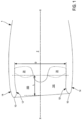
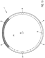
- a nacelle 1 of a turbomachine has a longitudinal axis XX around which it extends, for example with a shape of revolution around the longitudinal axis XX, typically a substantially cylindrical shape of revolution.
- a shape of revolution around the longitudinal axis XX typically a substantially cylindrical shape of revolution.
- the nacelle 1 can also extend around the longitudinal axis XX with a non-axisymmetric shape, that is to say a shape such that the longitudinal axis XX is not not orthogonal to the plane passing through all the points forming the upstream end of the nacelle 1.
- the nacelle 1 further comprises an inlet lip 10 defining an air inlet 100 through which air can be admitted into the turbomachine.
- the inlet lip 10 makes it possible to join, at an upstream end of the nacelle 1, an internal wall 12 of the nacelle 1, in contact with the air flow admitted within the turbomachine, with an external wall 14 of the nacelle 1, in contact with the air circulating around the turbomachine.
- the nacelle 1 generally surrounds a motor body 2 of the turbomachine, upstream of which a fan 20 extends.
- the blower 20 sucks the air flow admitted through the air inlet 100, and propels it inside the motor body 2.
- the fan 20 has a diameter D
- the air inlet 100 has a length L defined as the distance separating an upstream end of the inlet lip 10 from an upstream end of the fan 20. More precisely, as illustrated on the figure 1 , the length L corresponds to the distance between a leading edge of a foot of a blade of the fan 20 and the intersection between the longitudinal axis XX with the air capture plane, i.e.
- the length L corresponds to the distance between a leading edge of a foot of a blade of the fan 20 and a plane orthogonal to the leading edge of the inlet lip 10 taken at the level of a median plane of the nacelle 1 which contains the longitudinal axis XX and which is orthogonal to a plane of symmetry of the nacelle 1, ie a plane which passes through the azimuths 90° and 270° of the air inlet 100.
- the nacelle 1 has dimensions such that a ratio of the air inlet length L to the diameter of the fan D is between 0.15 and 0.25, and is worth preferably 0.19.
- the aerodynamic properties of the turbomachine are optimized with, in particular, minimized drag in relation to the master torque of the engine body 2, that is to say in relation to the dimensions of the engine body 2.
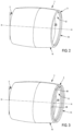
- a device for modifying a geometry of the air inlet 3 thanks to which the nacelle 1 can have at least two configurations illustrated in particular in figures 2 to 8 , 10 has 14 , And 16 .
- the geometry of the air inlet 100 is particularly suited to cruising flight conditions, at high speed of advancement of the aircraft to which the nacelle 1 is attached, inducing a high speed of air flow at the infinite upstream of the nacelle 1.
- This geometry of first configuration in fact allows a very homogeneous flow at the level of the air inlet 100.
- the device modification of a geometry of the air inlet 3 is in a retracted or folded position.
- the geometry of the air inlet 100 is particularly suited to flight conditions at takeoff, landing and/or at ground level, at lower air flow speed.
- This second configuration geometry makes it possible to provide a larger air suction surface, and to move the stopping point of the incoming flow downstream of the air inlet 100 so as to reduce the bypassing of the lip. inlet 10 through the flow.
- it helps minimize distortions in the flow of air flow at the air inlet, particularly in crosswind conditions, or high angles of attack.
- the device for modifying a geometry of the air inlet 3 is in a deployed position.
- the device for modifying a geometry of the air inlet 3 makes it possible to improve the capacity of the nacelle1 to reduce the distortion of the air flow admitted at the level of the air inlet 100, which makes it possible in particular to improve the aerodynamic behavior of the fan 20.
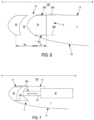
- the second nozzle 32 remains inside the nacelle 1, without interaction with the air flow circulating around the inlet lip 10, that is to say in a confined manner.
- the first nozzle 30 and the second nozzle 32 define an air flow channel 34 between a downstream surface of the first nozzle 30 and an upstream surface of the second nozzle 32.
- the air inlet 100 has a nominal geometry, that is to say particularly suited to cruising flight conditions, at high air flow speed, and, in the second configuration, the geometry of the air inlet 100 is modified so as to be particularly adapted to flight conditions at takeoff and/or at ground level, at lower air flow speed.
- the first configuration and the second configuration of the first nozzle 30 and the second nozzle 32 correspond, respectively, to the retracted position and the deployed position of the device for modifying a geometry of the air inlet 3.
- the device for modifying a geometry of the air inlet 3 can further comprise a guide rod 36 connecting the first nozzle 30 to the second nozzle 32, so that, on at least one angular portion of the device modification of a geometry of the air inlet 3, the first nozzle 30 is mounted fixed relative to the second nozzle 32.
- first nozzle 30 and the second nozzle 32 may not be mounted fixed relative to each other, on another angular portion of the device for modifying a geometry of the air inlet 3 where, for example the first nozzle and the second nozzle are connected by a rod guide 36 telescopic, so that the movement of the first nozzle 30 is independent of the movement of the second nozzle 32.
- the guide rod 36 extends parallel to the longitudinal axis XX, so as to facilitate the deployment and storage movements of the nozzles 30, 32 within the nacelle 1.
- the device for modifying a geometry of the air inlet 3 comprises a plurality of guide rods 36, distributed around the longitudinal axis XX, for example equally distributed azimuthaly.
- the device for modifying a geometry of the air inlet 3 has increased robustness, and the deployment and storage movements of the nozzles 30, 32 within the nacelle 1 can be implemented quickly. and precise.
- a system for defrosting the first nozzle 30 and/or the second nozzle 32.
- the defrosting system comprises a defrosting fluid circulation channel which extends at least partly to the interior of a guide rod 36.
- the guide rod 36 can therefore be at least partially hollow, so as to convey the defrosting fluid, for example hot air. This makes it possible in particular to ensure defrosting of the first nozzle 30 and/or the second nozzle 32 whatever the configuration of the device for modifying a geometry of the air inlet 3.
- the device for modifying a geometry of the air inlet 3 can further comprise an actuator 38, configured to be housed in the nacelle 1.
- the actuator 38 is also configured to set the first nozzle 30 in motion and /or the second nozzle 32, between the first configuration and the second configuration.
- the actuator 38 is configured to set the guide rod 36 in motion, so as to move from the first configuration to the second configuration, and vice versa.
- a rail(s) 380 extends parallel to the longitudinal axis XX and is configured to guide the first nozzle 30 and/or the second nozzle 32 in translation.
- the first nozzle 30 and/or the second nozzle 32 can advantageously be mounted in translation on the rail(s) 380.
- the rails 380 has an axial length ⁇ i .
- the axial length ⁇ i of the rails 380 is preferably less than or equal to the distance separating the inlet neck from the end of air inlet divergence 100.
- the actuator 38 can be pneumatic. In this case, it is possible to couple the defrosting system of the nacelle 1, for example hot air, with the actuator 38.
- a locking device configured to immobilize the device for modifying a geometry of the air inlet 3 in the first configuration and/or in the second configuration, deployment and storage can also be naturally ensured by the flow of air at high speed and/or low speed.
- the device for modifying a geometry of the air inlet 3 has significant robustness, and it is no longer necessary to provide emergency devices to compensate for a possible failure of the actuator 38.
- FIG. 10 is a sectional view of the device for modifying a geometry of the air inlet 3 along a radial plane P relative to the longitudinal axis XX, that is to say in a plane P comprising the longitudinal axis XX.
- the first beak 30 defines a third radius R3 which corresponds to the distance separating the longitudinal axis XX from an external radial face 301 of the first beak 30, and a fourth radius R4 which corresponds to the distance separating the longitudinal axis XX d an internal radial face 300 of the first nozzle 30.
- first nozzle 30 defines an upstream profile of the first nozzle C1.
- This upstream profile of first nozzle C1 forms an upstream surface of first nozzle 302, which is three-dimensional of revolution around the longitudinal axis XX.
- a section of the upstream profile of first nozzle C1 in the radial plane P then forms a geometric line connecting a geometric line formed from the section, in the radial plane P, of the internal radial face 300 of the first nozzle 30 to a geometric line formed by the section, in the radial plane P, of the external radial face 301 of the first nozzle 30, upstream of the first nozzle 30.
- This geometric line can be defined by any curve passing through the geometric line formed by the cut, in the radial plane P, of the internal radial face 300 of the first nozzle 30 and by geometric line formed by the cut, in the radial plane P, of the external radial face 301 of the first nozzle 30, upstream of the first nozzle 30.
- the upstream profile of the first nozzle C1 may have the shape of a geometric line different in another radial plane P', which also includes the longitudinal axis XX and which is different from the radial plane P.
- first nozzle 30 defines a downstream profile of first nozzle C2.
- This downstream profile of first nozzle C2 forms a downstream surface of first nozzle 303, which is three-dimensional of revolution around the longitudinal axis XX.
- a section of the downstream profile of first nozzle C2 in the radial plane P then forms a geometric line connecting a geometric line formed from the section, in the radial plane P, of the internal radial face 300 of the first nozzle 30 to a geometric line formed by the section, in the radial plane P, of the external radial face 301 of the first nose 30, downstream of the first nose 30.
- This geometric line can be defined by any curve passing through the geometric line formed by the cut, in the radial plane P, of the internal radial face 300 of the first nozzle 30 and by the geometric line formed by the section, in the radial plane P, of the external radial face 301 of the first nozzle 30, downstream of the first nozzle 30.
- the shape of the downstream surface of first nozzle 303, the downstream profile of first nozzle C2 may have a different shape of geometric line in another radial plane P', which also includes the longitudinal axis X-X and which is different from the radial plane P .
- the first beak 30 defines a radial span ⁇ corresponding to the difference between the third radius R3 and the fourth radius R4, that is to say the distance separating the internal radial face 300 of the first beak 30 from its face external radial 301.
- the radial span ⁇ is limited by the thickness e of the inlet lip 10, to be able to easily deploy and store the device for modifying a geometry of the air inlet 3.
- a ratio of the radial span ⁇ of first nozzle 30 to the thickness e of inlet lip 10 is between 0.4 and 0.6.
- the internal radial face 300 of the first nozzle 30 extends as close as possible to the longitudinal axis XX, that is to say substantially in the same plane as the surface of the internal wall 12 of the nacelle 1 which is furthest from the longitudinal axis XX, as visible on the Figure 10 .
- the air flow channel 34 opens as close as possible to the external radial surface of the air flow penetrating within the air inlet 100.
- the flow of The additional air injected through the air flow channel 34 has lines of current which are as parallel as possible to the current lines of said air flow penetrating within the air inlet 100.
- the first nozzle 30 defines an internal radial face length of the first nozzle H1, corresponding to the distance separating the internal radial end of the upstream profile of the first nozzle C1 from the internal radial end of a downstream surface of the first nozzle 30.
- the length of the internal radial face of the first nozzle H1 is dimensioned so that said internal radial face 300 can serve as a guide when moving from the first configuration to the second configuration, and vice versa.
- the length of the internal radial face of the first nozzle H1 is dimensioned so as to guarantee the sealing of the device for modifying the geometry of the air inlet 3 in the retracted position, by contact with the internal wall 12 of the nacelle 1. This makes it possible in particular to maintain the same aerodynamic performance, whatever the configuration of the device modification of the geometry of the air inlet 3, that is to say in the deployed position, in the retracted position, or in an intermediate position between these two positions.
- the first nozzle 30 defines a length of the outer radial face of the first nozzle H2, corresponding to the distance separating the outer radial end of the upstream profile of the first nozzle C1 from the outer radial end of a downstream surface of the first nozzle 30.
- the length of the outer radial face of first nozzle H2 is dimensioned so that said outer radial face 301 can serve as a guide when moving from the first configuration to the second configuration, and vice versa.
- the length of the external radial face of the first nozzle H2 is dimensioned so as to guarantee the sealing of the device for modifying the geometry of the air inlet 3 in the retracted position, by contact with the external wall 14 of the nacelle 1. This makes it possible in particular to maintain the same aerodynamic performance, whatever the configuration of the device modification of the geometry of the air inlet 3, that is to say in the deployed position, in the retracted position, or in an intermediate position between these two positions.
- the second nozzle 32 defines a length H i of the internal radial face 320 of the second nozzle 32, corresponding to the distance separating the internal radial end of the upstream profile of the second nozzle C3 from the internal radial end of a downstream surface of the second nozzle 32.
- This length H i is also equal to the length of the outer radial face 321 of second nozzle 32, corresponding to the distance separating the outer radial end of the upstream profile of second nozzle C3 of the outer radial end of a downstream surface of the second nozzle 32.
- the length of the internal and/or external radial face of the second nozzle H i is dimensioned so that it can serve as a guide when moving from the first configuration to the second configuration, and vice versa.
- the internal and/or external radial face length of the second nozzle H i is dimensioned so as to guarantee the sealing of the device for modifying the geometry of the air inlet 3 in the retracted position, by contact with the internal wall 12 of the nacelle 1. This makes it possible in particular to maintain the same aerodynamic performance, whatever the configuration of the device modification of the geometry of the air inlet 3, that is to say in the deployed position, in retracted position, or in an intermediate position between these two positions
- the second nozzle 32 also has an upstream profile of second nozzle C3.
- This upstream profile of second nozzle C3 forms an upstream surface of second nozzle 322, which is three-dimensional of revolution around the longitudinal axis XX.
- a section of the downstream profile of first nozzle C2 in the radial plane P then forms a geometric line connecting a geometric line formed from the section, in the radial plane P, of the internal radial face 320 of the second nozzle 32 to a geometric line formed by the section, in the radial plane P, of the external radial face 321 of the second nozzle 32.
- This geometric line can be defined by any curve passing through the geometric line formed by the section, in the radial plane P, of the internal radial face 320 of the second nozzle 32 and by the geometric line formed by the section, in the radial plane P, of the external radial face 321 of the second nozzle 32.
- the upstream profile second nozzle C3 may have a different geometric line shape in another radial plane P', which also includes the longitudinal axis XX and which is different from the radial plane P.
- the upstream profile of the second nozzle C3 presents, in the second configuration, tangential continuity with a profile of the nacelle 1 defined in the radial plane P. More precisely, as visible on the Figure 10 , the nacelle 1 also has a profile in the radial plane P which takes the form of two geometric lines corresponding respectively to the internal wall 12 and to the external wall 14 of the nacelle 1. However, at the intersection of the upstream profile of second nozzle C3 with the profile of the nacelle 1, respectively at the level of the internal wall 12 and the wall external 14, a local tangent of the upstream profile of second nozzle C3 is coincident with a local tangent of the nacelle profile 1.
- the second nozzle 32 in the second configuration, exactly matches the respective edges of the internal wall 12 and the external wall 14 of the nacelle 1, so as to offer no disturbance to the air flow penetrating within the air inlet 100. This ensures minimization of additional disturbances to the air flow.
- This tangential continuity of second configuration is present in any radial plane, all around the longitudinal axis XX.
- the upstream profile of first nozzle C1 is identical to the upstream profile of second nozzle C3. More precisely, in any radial plane P, the geometric line defining the upstream profile of first nozzle C1 is identical to the geometric line defining the upstream profile of second nozzle C3, that is to say they can be exactly superimposed on their entire length. In this way, the inlet lip 10 has exactly the same shape in the first configuration and in the second configuration.
- the internal axial length ⁇ 1 of the air flow channel 34 is less than the external axial length ⁇ 2 of the flow channel air 34. This makes it possible to define a converging geometry of air flow channel 34, as visible on the Figure 10 .
- the internal axial length ⁇ 1 and the external axial length ⁇ 2 are invariant whatever the position of the device for modifying a geometry of the air inlet 3.
- the device for modifying a geometry of the air inlet 3 defines a maximum axial span ⁇ as the greatest of the distance separating the external radial end of the upstream profile of first nozzle C1 from the radial end external of the upstream rim of internal wall 12 of the nacelle 1, and of the distance separating the internal radial end of the upstream profile of first nozzle C1 from the internal radial end of the upstream rim of internal wall 12 of the nacelle 1, when the device for modifying a geometry of the air inlet 3 is in the deployed position.
- the maximum axial span ⁇ corresponds to the axial span ⁇ e of the device for modifying a geometry of the air inlet 3 when it is in the deployed position.
- the space available for the extension of the device for modifying a geometry of the air inlet 3 is limited within the nacelle 1, when said device for modifying a geometry of the air inlet 3 is in the first configuration, that is to say in the retracted position.
- the axial length ⁇ i of the rails 380 is preferably equal to the axial span ⁇ e in the retracted position, and in any case is not less than the axial span ⁇ e .
- the internal axial length of the air flow channel ⁇ 1 and the external axial length of the air flow channel ⁇ 2 are each less than the axial span ⁇ e of the device for modifying a geometry of the air inlet 3. In addition, they are each advantageously non-zero, to guarantee the existence of the air flow channel 34. Furthermore, in an embodiment where the first nozzle 30 and the second nozzle 32 can be set in axial movement independently of each other, the internal axial length of air flow channel ⁇ 1 and the external axial length of air flow channel ⁇ 2 can take a minimum value which depends on the point of contact between the first nozzle 30 and the second nozzle 32. This is particularly visible on the figure 5 . As visible in this figure, this allows an advantageous saving of space in the retracted position.
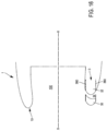
- the air flow channel 34 has, in the first radial plane P1, a first longitudinal section, and in the second radial plane P2, a second longitudinal section, the second longitudinal section being different from the first longitudinal section.
- longitudinal section we understand a section of the air flow channel 34 taken along a radial plane relative to the longitudinal axis XX.
- THE figures 11 to 13 thus illustrate different longitudinal sections of the air flow channel 34 respectively in the first configuration of a device for modifying a geometry of the air inlet 3, and in the second configuration of said device 3.
- a first longitudinal section is convergent in a first radial plane P1
- a second longitudinal section is convergent-divergent in a second radial plane P2
- the air flow channel 34 initially narrows to as it approaches the longitudinal axis XX, then increases again until it opens into the air inlet 100.
- the stopping point of the flow is generally located outside the nacelle 1, and the air flow bypasses the inlet lip 10 from the outside towards the inside over the entire the circumference of the nacelle 1.
- the stopping point can be located more towards the interior of the nacelle 1 in the second radial plane P2, but outside in the first radial plane P1.
- the different shape in the two radial planes P1 and P2 allows the flow to bypass the inlet lip 10 in both directions in the second radial plane P2, while, in the first radial plane P1, the flow always bypasses the inlet lip 10 in the same direction.
- the convergence can be defined by the respective choice of the length of the internal radial face of the first nozzle H1 and the length of the external radial face of the first nozzle H2, which are also each limited by the axial span ⁇ of the device of modification of a geometry of the air inlet 3.
- the air flow channel 34 makes it possible, in the second configuration, to provide an additional modification of the momentum within the fluid admitted by the air inlet 100.
- This modification may consist of an acceleration or a deceleration of the admitted fluid.
- an acceleration is generally sought, and the convergence rate ⁇ must then be less than 1, that is to say that the longitudinal section of the flow channel of air 34 is convergent.
- the structure of the device for modifying a geometry of the air inlet 3 allows both significant convergence rates ⁇ , that is to say close to 0, but also very weak, that is to say close to 1, or even divergences, that is to say when the convergence rate ⁇ is greater than 1.
- first longitudinal section of the air flow channel 34 in a first radial plane P1 is different from a second longitudinal section, in a second radial plane P2
- the axial span ⁇ of the device modification of a geometry of the air inlet 3 is the same in the first plane P1 and in the second plane P2, as visible for example on the figures 11 and 12 . This guarantees simple rectilinear translation of the device for modifying the geometry of the air inlet 3.
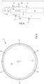
- the first nozzle 30 and the second nozzle 32 have a symmetry of revolution around of the longitudinal axis XX, in at least one given angular sector.
- This allows easy implementation of the deployment and storage of the device for modifying a geometry of the air inlet 3, while ensuring compactness of the nacelle 1 both in the first configuration and in the second configuration .
- this minimizes disturbances within the flow admitted by the air inlet 100.
- the upstream profiles C1, C3 of the nozzles 30, 32 may or may not have a symmetry of revolution around the longitudinal axis XX in at least one given angular sector.
- the deployment and storage of the device for modifying a geometry of the air inlet 3 are in all cases facilitated by the fact that the internal radial faces 300, 320 and external 301, 321 of the nozzles 30, 32 are generating a cylinder of revolution around the longitudinal axis XX, which is also the direction of deployment and storage.
- first nozzle 30 and/or second nozzle 32 can be moved between the first configuration and the second configuration, and vice versa, independently of each other.
- the device for modifying a geometry of the air inlet 3 can comprise a plurality of first nozzles 30 connected to a plurality of second nozzles 32, each extending in an angular portion around the longitudinal axis X-X, and each being movable in translation between a first configuration and a second configuration.
- a first nozzle 30 and a second nozzle 32 may be in the first configuration, while another first nozzle 30 and another second nozzle 32 are in the second configuration.
- the plurality of first nozzles 30 and the plurality of second nozzles can also have upstream profiles C1, C3 and downstream C2 which are different from each other.
- an air flow channel 34 is not necessary, or even undesirable, for angular portions of the air inlet 100, typically the upper azimuthal portion, as illustrated in the figures 14 to 17 . Indeed, the presence of the air flow channel 34 could generate aerodynamic disturbances in addition to the strong incidences within the flow at the level of these air inlet portions 100.
- the first nozzle 30 and the second nozzle 32 are connected in such a way that the internal axial length ⁇ 1 and the external axial length ⁇ 2 of the air flow channel 34 is zero.
- the first nozzle 30 and the second nozzle 32 then form a single nozzle 33, also movable in translation along the longitudinal axis XX relative to the nacelle 1.
- the first nozzle 30 and the second nozzle 32 do not extend all around the longitudinal axis XX, but only along an angular portion, for example on the lateral and lower parts of the air inlet 100.
- the part upper part of the air inlet 100 is then bordered by an air inlet lip 10 fixed relative to the nacelle 1.
- the first nozzle 30 and the second spout 32 extend over a first angular portion of the nacelle 1, a second angular portion of the nacelle being bordered by a fixed part of the air inlet lip 10. More precisely, on this second angular portion, the lip air inlet 10 does not include a device for modifying a geometry of the air inlet 3.
Landscapes
- Engineering & Computer Science (AREA)
- Chemical & Material Sciences (AREA)
- Combustion & Propulsion (AREA)
- Aviation & Aerospace Engineering (AREA)
- Mechanical Engineering (AREA)
- General Engineering & Computer Science (AREA)
- Physics & Mathematics (AREA)
- Geometry (AREA)
- Structures Of Non-Positive Displacement Pumps (AREA)
- Wind Motors (AREA)
- Jet Pumps And Other Pumps (AREA)
Claims (12)
- Anordnung für eine Turbomaschine, umfassend:- eine Gondel (1), die eine Längsachse (X-X) aufweist und eine Eingangslippe (10) umfasst, die einen Lufteinlass (100) definiert, und- eine Vorrichtung zum Verändern einer Geometrie des Lufteinlasses (3), wobei die Vorrichtung (3) umfasst:- eine erste Nase (30), und- eine zweite Nase (32),wobei die erste Nase (30) und die zweite Nase (32) gemäß der Längsachse (X-X) im Verhältnis zur Gondel (1) translatorisch beweglich sind zwischen:- einer ersten Konfiguration, in der die erste Nase (30) die Eingangslippe (10) bildet und sich die zweite Nase (32) im Inneren der Gondel (1) erstreckt, und- einer zweiten Konfiguration, in der sich die erste Nase (30) beabstandet von der Eingangslippe (10) erstreckt und die zweite Nase (32) die Eingangslippe (10) bildet, so dass ein Luftströmungskanal (34) zwischen einer stromabwärtigen Oberfläche der ersten Nase (30) und einer stromaufwärtigen Oberfläche der zweiten Nase (32) definiert wird,wobei die Anordnung dadurch gekennzeichnet ist, dass die erste Nase aufweist:- in einer ersten radialen Ebene (P1) im Verhältnis zur Längsachse (X-X) ein erstes stromabwärtiges erstes Nasenprofil (C21), und- in einer zweiten radialen Ebene (P2) im Verhältnis zur Längsachse (X-X) ein zweites stromabwärtiges erstes Nasenprofil (C22),wobei das zweite stromabwärtige erste Nasenprofil (C22) vom ersten stromabwärtigen ersten Nasenprofil (C21) unterschiedlich ist, so dass der Luftströmungskanal (34) in der ersten radialen Ebene (P1) einen ersten Längsschnitt und in der zweiten radialen Ebene (P2) einen zweiten Längsschnitt aufweist, wobei der zweite Längsschnitt vom ersten Längsschnitt unterschiedlich ist.
- Anordnung für eine Turbomaschine nach Anspruch 1, wobei die zweite Nase (32) in einer radialen Ebene (P) im Verhältnis zur Längsachse (X-X) ein stromaufwärtiges zweites Nasenprofil (C3) aufweist, wobei das stromaufwärtige zweite Nasenprofil (C3) in der zweiten Konfiguration eine Tangentialkontinuität mit einem in der radialen Ebene (P) definierten Profil der Gondel (1) aufweist.
- Anordnung für eine Turbomaschine nach einem der Ansprüche 1 und 2, wobei die erste Nase (30) in einer radialen Ebene (P) im Verhältnis zur Längsachse (X- X) ein stromaufwärtiges erstes Nasenprofil (C1) aufweist und die zweite Nase (32) in der radialen Ebene (P) ein stromaufwärtiges zweites Nasenprofil (C3) aufweist, wobei das stromaufwärtige zweite Nasenprofil (C3) mit dem stromaufwärtigen ersten Nasenprofil (C1) identisch ist.
- Anordnung für eine Turbomaschine nach einem der Ansprüche 1 bis 3, wobei die zweite Nase (32) aufweist:- in einer ersten radialen Ebene (P1) im Verhältnis zur Längsachse (X-X) ein erstes stromaufwärtiges zweites Nasenprofil (C31), und- in einer zweiten radialen Ebene (P2) im Verhältnis zur Längsachse (X-X) ein zweites stromaufwärtiges zweites Nasenprofil (C32),- wobei das zweite stromaufwärtige zweite Nasenprofil (C32) vom ersten stromaufwärtigen zweiten Nasenprofil (C31) unterschiedlich ist, so dass der Luftströmungskanal (34) in der ersten radialen Ebene (P1) einen ersten Längsschnitt und in der zweiten radialen Ebene (P2) einen zweiten Längsschnitt aufweist, wobei der zweite Längsschnitt vom ersten Längsschnitt unterschiedlich ist.
- Anordnung für eine Turbomaschine nach einem der Ansprüche 1 bis 4, wobei über mindestens einen Winkelabschnitt der Vorrichtung zum Verändern einer Geometrie des Lufteinlasses (3) die erste Nase (30) und die zweite Nase (32) derart verbunden sind, dass sie eine einzige Nase (33) bilden, die ebenfalls gemäß der Längsachse (X-X) im Verhältnis zur Gondel (1) translatorisch beweglich ist.
- Anordnung für eine Turbomaschine nach einem der Ansprüche 1 bis 5, wobei sich die erste Nase (30) und die zweite Nase (32) über einen ersten Winkelabschnitt der Gondel (1) erstrecken, wobei ein zweiter Winkelabschnitt der Gondel (2) von einem festen Teil der Lufteingangslippe (10) gesäumt ist.
- Anordnung für eine Turbomaschine nach einem der Ansprüche 1 bis 6, wobei die Vorrichtung zum Verändern einer Geometrie des Lufteinlasses (3) eine Führungsstange (36) umfasst, die sich parallel zur Längsachse (X-X) erstreckt und die erste Nase (30) mit der zweiten Nase (32) derart verbindet, dass über mindestens einen Winkelabschnitt der Vorrichtung zum Verändern einer Geometrie des Lufteinlasses (3) die erste Nase (30) im Verhältnis zur zweiten Nase (32) fest angebracht ist.
- Anordnung für eine Turbomaschine nach einem der Ansprüche 1 bis 7, wobei die Vorrichtung zum Verändern einer Geometrie des Lufteinlasses (3) eine Führungsstange (36) umfasst, die sich parallel zur Längsachse (X-X) erstreckt, wobei die Führungsstange (36) teleskopisch ist, so dass über mindestens einen Winkelabschnitt der Vorrichtung zum Verändern einer Geometrie des Lufteinlasses (3) die Bewegung der ersten Nase (30) von der Bewegung der zweiten Nase (32) unabhängig ist.
- Anordnung für eine Turbomaschine nach einem der Ansprüche 7 und 8, umfassend ein Enteisungssystem der ersten Nase (30) und/oder der zweiten Nase (32), umfassend einen Zirkulationskanal für Enteisungsfluid, der sich mindestens zum Teil im Inneren der Führungsstange (36) erstreckt.
- Anordnung für eine Turbomaschine nach einem der Ansprüche 1 bis 9, wobei die Vorrichtung zum Verändern einer Geometrie des Lufteinlasses (3) ferner einen Aktuator (36) umfasst, der in der Gondel (1) untergebracht und dazu ausgelegt ist, die erste Nase (30) und die zweite Nase (32) zwischen der ersten Konfiguration und der zweiten Konfiguration in Bewegung zu versetzen.
- Anordnung für eine Turbomaschine nach einem der Ansprüche 1 bis 10, wobei die Gondel (1) eine nicht achssymmetrische Form aufweist.
- Turbomaschine, umfassend eine Anordnung nach einem der Ansprüche 1 bis 11.
Applications Claiming Priority (2)
| Application Number | Priority Date | Filing Date | Title |
|---|---|---|---|
| FR1911490A FR3101854B1 (fr) | 2019-10-15 | 2019-10-15 | Nacelle de turbomachine |
| PCT/FR2020/051841 WO2021074535A1 (fr) | 2019-10-15 | 2020-10-15 | Ensemble pour turbomachine |
Publications (2)
| Publication Number | Publication Date |
|---|---|
| EP4045397A1 EP4045397A1 (de) | 2022-08-24 |
| EP4045397B1 true EP4045397B1 (de) | 2024-07-31 |
Family
ID=69190963
Family Applications (1)
| Application Number | Title | Priority Date | Filing Date |
|---|---|---|---|
| EP20799779.2A Active EP4045397B1 (de) | 2019-10-15 | 2020-10-15 | Anordnung für eine turbomaschine |
Country Status (5)
| Country | Link |
|---|---|
| US (1) | US11913378B2 (de) |
| EP (1) | EP4045397B1 (de) |
| CN (1) | CN114981162B (de) |
| FR (1) | FR3101854B1 (de) |
| WO (1) | WO2021074535A1 (de) |
Families Citing this family (4)
| Publication number | Priority date | Publication date | Assignee | Title |
|---|---|---|---|---|
| US10221764B2 (en) * | 2014-08-19 | 2019-03-05 | Pratt & Whitney Canada Corp. | Variable geometry inlet system |
| US12435666B1 (en) * | 2024-10-09 | 2025-10-07 | General Electric Company | Turbine engine having a variable engine intake system |
| US12442333B1 (en) | 2024-10-09 | 2025-10-14 | General Electric Company | Turbine engine having a variable engine intake system |
| US12529335B1 (en) | 2024-10-09 | 2026-01-20 | General Electric Company | Turbine engine having a variable engine intake system |
Citations (2)
| Publication number | Priority date | Publication date | Assignee | Title |
|---|---|---|---|---|
| DE2318380B2 (de) * | 1973-04-12 | 1976-10-07 | Dornier Gmbh, 7990 Friedrichshafen | Lufteinlauf fuer flugtriebwerke |
| US20180371996A1 (en) * | 2017-06-26 | 2018-12-27 | The Boeing Company | Translating turning vanes for a nacelle inet |
Family Cites Families (12)
| Publication number | Priority date | Publication date | Assignee | Title |
|---|---|---|---|---|
| US5014933A (en) * | 1989-04-27 | 1991-05-14 | The Boeing Company | Translating lip aircraft cowling structure adapted for noise reduction |
| US5000399A (en) * | 1990-02-23 | 1991-03-19 | General Electric Company | Variable contour annular air inlet for an aircraft engine nacelle |
| DE4009223A1 (de) * | 1990-03-22 | 1991-09-26 | Mtu Muenchen Gmbh | Propfan-turbotriebwerk |
| US7131612B2 (en) * | 2003-07-29 | 2006-11-07 | Pratt & Whitney Canada Corp. | Nacelle inlet lip anti-icing with engine oil |
| FR2906568B1 (fr) * | 2006-10-02 | 2012-01-06 | Aircelle Sa | Structure d'entree d'air deposable pour nacelle de turboreacteur. |
| FR2927061B1 (fr) * | 2008-02-01 | 2010-02-12 | Aircelle Sa | Systeme de verrouillage pour structure d'entree d'air d'une nacelle de turboreacteur |
| US8181905B2 (en) * | 2008-12-17 | 2012-05-22 | Rohr, Inc. | Aircraft engine nacelle with translating inlet cowl |
| FR2942457B1 (fr) * | 2009-02-24 | 2011-04-22 | Snecma | Nacelle de turboreacteur a structure d'entree d'air amovible |
| US7871455B1 (en) * | 2009-06-19 | 2011-01-18 | Vintage Capital Group, Llc | Jet engine protection system |
| US8366057B2 (en) * | 2009-07-28 | 2013-02-05 | University Of Kansas | Method and apparatus for pressure adaptive morphing structure |
| FR2975972B1 (fr) * | 2011-06-01 | 2013-11-22 | Aircelle Sa | Structure d'entree d'air de nacelle de turboreacteur |
| DE102011103163A1 (de) * | 2011-06-01 | 2012-12-06 | Rolls-Royce Deutschland Ltd & Co Kg | Gasturbinentriebwerk mit teleskopartigem Lufteinlass der Triebwerksverkleidung |
-
2019
- 2019-10-15 FR FR1911490A patent/FR3101854B1/fr active Active
-
2020
- 2020-10-15 EP EP20799779.2A patent/EP4045397B1/de active Active
- 2020-10-15 US US17/768,933 patent/US11913378B2/en active Active
- 2020-10-15 CN CN202080078192.1A patent/CN114981162B/zh active Active
- 2020-10-15 WO PCT/FR2020/051841 patent/WO2021074535A1/fr not_active Ceased
Patent Citations (2)
| Publication number | Priority date | Publication date | Assignee | Title |
|---|---|---|---|---|
| DE2318380B2 (de) * | 1973-04-12 | 1976-10-07 | Dornier Gmbh, 7990 Friedrichshafen | Lufteinlauf fuer flugtriebwerke |
| US20180371996A1 (en) * | 2017-06-26 | 2018-12-27 | The Boeing Company | Translating turning vanes for a nacelle inet |
Also Published As
| Publication number | Publication date |
|---|---|
| CN114981162B (zh) | 2026-02-13 |
| FR3101854B1 (fr) | 2024-05-31 |
| CN114981162A (zh) | 2022-08-30 |
| FR3101854A1 (fr) | 2021-04-16 |
| EP4045397A1 (de) | 2022-08-24 |
| WO2021074535A1 (fr) | 2021-04-22 |
| US20230349323A1 (en) | 2023-11-02 |
| US11913378B2 (en) | 2024-02-27 |
Similar Documents
| Publication | Publication Date | Title |
|---|---|---|
| EP4045397B1 (de) | Anordnung für eine turbomaschine | |
| FR3133367A1 (fr) | Propulseur aeronautique | |
| FR3078098A1 (fr) | Structure a profil en serrations inclinees | |
| CA2169874C (fr) | Inverseur de poussee a volets aval pour turboreacteur | |
| WO2016132073A1 (fr) | Ensemble propulsif pour aeronef comprenant un turboreacteur a soufflante non carenee et un pylone d'accrochage | |
| FR3082230A1 (fr) | Moteur d'aeronef a rotor non carene avec adaptation des aubes de stator | |
| FR2933953A1 (fr) | Avion a empennage vertical a surface variable | |
| FR2938502A1 (fr) | Turbomachine comportant une helice non carenee equipee de moyens de guidage d'air | |
| CA2743009C (fr) | Entree d'air d'un moteur d'avion a helices propulsives non carenees | |
| FR3027065A1 (fr) | Grille deployable a ailettes pour systeme d'inversion de poussee de turbomachine d'aeronef | |
| FR3021706A1 (fr) | Turbopropulseur d'aeronef comportant deux helices coaxiales. | |
| EP4077880B1 (de) | Turbomaschinenmodul | |
| EP3956226B1 (de) | Verfahren zur verwendung eines lufteintritts einer turboreaktorgondel mit einer lufteinlasslippe mit einem abschnitt, der bewegt werden kann, um eine schubumkehrphase zu fördern | |
| EP4025789B1 (de) | Polyspherische nabe einer turbomaschine für verstellbare schaufeln | |
| FR3052191B1 (fr) | Inversion de poussee dans une turbomachine avec soufflante a calage variable | |
| FR3079211A1 (fr) | Ensemble propulsif d'aeronef comportant deux moteurs adjacents, dont les tuyeres de sorties presentent une portion droite a proximite d'un plan median de l'ensemble propulsif | |
| EP4392655A1 (de) | Umkehrer mit beweglichen kaskaden für eine flugzeugantriebsanordnung mit einem system zur begrenzung der biegung eines aktuators des umkehrers | |
| WO2021136898A1 (fr) | Inverseur de poussée comprenant des portes formant en position ouverte une ouverture de déflexion d'air vers le haut | |
| EP4240650B1 (de) | Gondellufteinlass für eine flugzeugantriebsanordnung zur förderung einer schubumkehrphase | |
| WO2021140053A1 (fr) | Tuyère à section de sortie variable pour moteur de fusée et moteur de fusée comportant une telle tuyère | |
| EP4100638B1 (de) | Luftausströmer für eine flugzeugtriebwerksgondel mit einer richtvorrichtung zur unterstützung einer rückschubphase | |
| FR2477100A1 (fr) | Systeme d'ejection d'air de dilution de moteur a turbosoufflante | |
| WO2024241010A1 (fr) | Inverseur de poussee comprenant au moins une membrane deployable de deviation | |
| FR3149045A1 (fr) | Inverseur de poussee comprenant au moins une membrane déployable de déviation | |
| FR3114615A1 (fr) | Manche d’entree d’air filtrant la distorsion pour une nacelle d’un ensemble propulsif d’aeronef |
Legal Events
| Date | Code | Title | Description |
|---|---|---|---|
| STAA | Information on the status of an ep patent application or granted ep patent |
Free format text: STATUS: UNKNOWN |
|
| STAA | Information on the status of an ep patent application or granted ep patent |
Free format text: STATUS: THE INTERNATIONAL PUBLICATION HAS BEEN MADE |
|
| PUAI | Public reference made under article 153(3) epc to a published international application that has entered the european phase |
Free format text: ORIGINAL CODE: 0009012 |
|
| STAA | Information on the status of an ep patent application or granted ep patent |
Free format text: STATUS: REQUEST FOR EXAMINATION WAS MADE |
|
| 17P | Request for examination filed |
Effective date: 20220511 |
|
| AK | Designated contracting states |
Kind code of ref document: A1 Designated state(s): AL AT BE BG CH CY CZ DE DK EE ES FI FR GB GR HR HU IE IS IT LI LT LU LV MC MK MT NL NO PL PT RO RS SE SI SK SM TR |
|
| DAV | Request for validation of the european patent (deleted) | ||
| DAX | Request for extension of the european patent (deleted) | ||
| GRAP | Despatch of communication of intention to grant a patent |
Free format text: ORIGINAL CODE: EPIDOSNIGR1 |
|
| STAA | Information on the status of an ep patent application or granted ep patent |
Free format text: STATUS: GRANT OF PATENT IS INTENDED |
|
| GRAJ | Information related to disapproval of communication of intention to grant by the applicant or resumption of examination proceedings by the epo deleted |
Free format text: ORIGINAL CODE: EPIDOSDIGR1 |
|
| STAA | Information on the status of an ep patent application or granted ep patent |
Free format text: STATUS: REQUEST FOR EXAMINATION WAS MADE |
|
| INTG | Intention to grant announced |
Effective date: 20240208 |
|
| GRAP | Despatch of communication of intention to grant a patent |
Free format text: ORIGINAL CODE: EPIDOSNIGR1 |
|
| STAA | Information on the status of an ep patent application or granted ep patent |
Free format text: STATUS: GRANT OF PATENT IS INTENDED |
|
| INTC | Intention to grant announced (deleted) | ||
| INTG | Intention to grant announced |
Effective date: 20240405 |
|
| GRAS | Grant fee paid |
Free format text: ORIGINAL CODE: EPIDOSNIGR3 |
|
| GRAA | (expected) grant |
Free format text: ORIGINAL CODE: 0009210 |
|
| STAA | Information on the status of an ep patent application or granted ep patent |
Free format text: STATUS: THE PATENT HAS BEEN GRANTED |
|
| AK | Designated contracting states |
Kind code of ref document: B1 Designated state(s): AL AT BE BG CH CY CZ DE DK EE ES FI FR GB GR HR HU IE IS IT LI LT LU LV MC MK MT NL NO PL PT RO RS SE SI SK SM TR |
|
| REG | Reference to a national code |
Ref country code: CH Ref legal event code: EP Ref country code: GB Ref legal event code: FG4D Free format text: NOT ENGLISH |
|
| REG | Reference to a national code |
Ref country code: DE Ref legal event code: R096 Ref document number: 602020034958 Country of ref document: DE |
|
| REG | Reference to a national code |
Ref country code: IE Ref legal event code: FG4D Free format text: LANGUAGE OF EP DOCUMENT: FRENCH |
|
| REG | Reference to a national code |
Ref country code: LT Ref legal event code: MG9D |
|
| REG | Reference to a national code |
Ref country code: NL Ref legal event code: MP Effective date: 20240731 |
|
| PG25 | Lapsed in a contracting state [announced via postgrant information from national office to epo] |
Ref country code: PT Free format text: LAPSE BECAUSE OF FAILURE TO SUBMIT A TRANSLATION OF THE DESCRIPTION OR TO PAY THE FEE WITHIN THE PRESCRIBED TIME-LIMIT Effective date: 20241202 |
|
| REG | Reference to a national code |
Ref country code: AT Ref legal event code: MK05 Ref document number: 1708245 Country of ref document: AT Kind code of ref document: T Effective date: 20240731 |
|
| PG25 | Lapsed in a contracting state [announced via postgrant information from national office to epo] |
Ref country code: PT Free format text: LAPSE BECAUSE OF FAILURE TO SUBMIT A TRANSLATION OF THE DESCRIPTION OR TO PAY THE FEE WITHIN THE PRESCRIBED TIME-LIMIT Effective date: 20241202 |
|
| PG25 | Lapsed in a contracting state [announced via postgrant information from national office to epo] |
Ref country code: NO Free format text: LAPSE BECAUSE OF FAILURE TO SUBMIT A TRANSLATION OF THE DESCRIPTION OR TO PAY THE FEE WITHIN THE PRESCRIBED TIME-LIMIT Effective date: 20241031 |
|
| PG25 | Lapsed in a contracting state [announced via postgrant information from national office to epo] |
Ref country code: FI Free format text: LAPSE BECAUSE OF FAILURE TO SUBMIT A TRANSLATION OF THE DESCRIPTION OR TO PAY THE FEE WITHIN THE PRESCRIBED TIME-LIMIT Effective date: 20240731 Ref country code: NL Free format text: LAPSE BECAUSE OF FAILURE TO SUBMIT A TRANSLATION OF THE DESCRIPTION OR TO PAY THE FEE WITHIN THE PRESCRIBED TIME-LIMIT Effective date: 20240731 Ref country code: PL Free format text: LAPSE BECAUSE OF FAILURE TO SUBMIT A TRANSLATION OF THE DESCRIPTION OR TO PAY THE FEE WITHIN THE PRESCRIBED TIME-LIMIT Effective date: 20240731 Ref country code: GR Free format text: LAPSE BECAUSE OF FAILURE TO SUBMIT A TRANSLATION OF THE DESCRIPTION OR TO PAY THE FEE WITHIN THE PRESCRIBED TIME-LIMIT Effective date: 20241101 |
|
| PG25 | Lapsed in a contracting state [announced via postgrant information from national office to epo] |
Ref country code: BG Free format text: LAPSE BECAUSE OF FAILURE TO SUBMIT A TRANSLATION OF THE DESCRIPTION OR TO PAY THE FEE WITHIN THE PRESCRIBED TIME-LIMIT Effective date: 20240731 |
|
| PG25 | Lapsed in a contracting state [announced via postgrant information from national office to epo] |
Ref country code: LV Free format text: LAPSE BECAUSE OF FAILURE TO SUBMIT A TRANSLATION OF THE DESCRIPTION OR TO PAY THE FEE WITHIN THE PRESCRIBED TIME-LIMIT Effective date: 20240731 |
|
| PG25 | Lapsed in a contracting state [announced via postgrant information from national office to epo] |
Ref country code: AT Free format text: LAPSE BECAUSE OF FAILURE TO SUBMIT A TRANSLATION OF THE DESCRIPTION OR TO PAY THE FEE WITHIN THE PRESCRIBED TIME-LIMIT Effective date: 20240731 Ref country code: IS Free format text: LAPSE BECAUSE OF FAILURE TO SUBMIT A TRANSLATION OF THE DESCRIPTION OR TO PAY THE FEE WITHIN THE PRESCRIBED TIME-LIMIT Effective date: 20241130 |
|
| PG25 | Lapsed in a contracting state [announced via postgrant information from national office to epo] |
Ref country code: HR Free format text: LAPSE BECAUSE OF FAILURE TO SUBMIT A TRANSLATION OF THE DESCRIPTION OR TO PAY THE FEE WITHIN THE PRESCRIBED TIME-LIMIT Effective date: 20240731 |
|
| PG25 | Lapsed in a contracting state [announced via postgrant information from national office to epo] |
Ref country code: RS Free format text: LAPSE BECAUSE OF FAILURE TO SUBMIT A TRANSLATION OF THE DESCRIPTION OR TO PAY THE FEE WITHIN THE PRESCRIBED TIME-LIMIT Effective date: 20241031 Ref country code: ES Free format text: LAPSE BECAUSE OF FAILURE TO SUBMIT A TRANSLATION OF THE DESCRIPTION OR TO PAY THE FEE WITHIN THE PRESCRIBED TIME-LIMIT Effective date: 20240731 |
|
| PG25 | Lapsed in a contracting state [announced via postgrant information from national office to epo] |
Ref country code: RS Free format text: LAPSE BECAUSE OF FAILURE TO SUBMIT A TRANSLATION OF THE DESCRIPTION OR TO PAY THE FEE WITHIN THE PRESCRIBED TIME-LIMIT Effective date: 20241031 Ref country code: PL Free format text: LAPSE BECAUSE OF FAILURE TO SUBMIT A TRANSLATION OF THE DESCRIPTION OR TO PAY THE FEE WITHIN THE PRESCRIBED TIME-LIMIT Effective date: 20240731 Ref country code: NO Free format text: LAPSE BECAUSE OF FAILURE TO SUBMIT A TRANSLATION OF THE DESCRIPTION OR TO PAY THE FEE WITHIN THE PRESCRIBED TIME-LIMIT Effective date: 20241031 Ref country code: NL Free format text: LAPSE BECAUSE OF FAILURE TO SUBMIT A TRANSLATION OF THE DESCRIPTION OR TO PAY THE FEE WITHIN THE PRESCRIBED TIME-LIMIT Effective date: 20240731 Ref country code: LV Free format text: LAPSE BECAUSE OF FAILURE TO SUBMIT A TRANSLATION OF THE DESCRIPTION OR TO PAY THE FEE WITHIN THE PRESCRIBED TIME-LIMIT Effective date: 20240731 Ref country code: IS Free format text: LAPSE BECAUSE OF FAILURE TO SUBMIT A TRANSLATION OF THE DESCRIPTION OR TO PAY THE FEE WITHIN THE PRESCRIBED TIME-LIMIT Effective date: 20241130 Ref country code: HR Free format text: LAPSE BECAUSE OF FAILURE TO SUBMIT A TRANSLATION OF THE DESCRIPTION OR TO PAY THE FEE WITHIN THE PRESCRIBED TIME-LIMIT Effective date: 20240731 Ref country code: GR Free format text: LAPSE BECAUSE OF FAILURE TO SUBMIT A TRANSLATION OF THE DESCRIPTION OR TO PAY THE FEE WITHIN THE PRESCRIBED TIME-LIMIT Effective date: 20241101 Ref country code: FI Free format text: LAPSE BECAUSE OF FAILURE TO SUBMIT A TRANSLATION OF THE DESCRIPTION OR TO PAY THE FEE WITHIN THE PRESCRIBED TIME-LIMIT Effective date: 20240731 Ref country code: ES Free format text: LAPSE BECAUSE OF FAILURE TO SUBMIT A TRANSLATION OF THE DESCRIPTION OR TO PAY THE FEE WITHIN THE PRESCRIBED TIME-LIMIT Effective date: 20240731 Ref country code: BG Free format text: LAPSE BECAUSE OF FAILURE TO SUBMIT A TRANSLATION OF THE DESCRIPTION OR TO PAY THE FEE WITHIN THE PRESCRIBED TIME-LIMIT Effective date: 20240731 Ref country code: AT Free format text: LAPSE BECAUSE OF FAILURE TO SUBMIT A TRANSLATION OF THE DESCRIPTION OR TO PAY THE FEE WITHIN THE PRESCRIBED TIME-LIMIT Effective date: 20240731 |
|
| PG25 | Lapsed in a contracting state [announced via postgrant information from national office to epo] |
Ref country code: SM Free format text: LAPSE BECAUSE OF FAILURE TO SUBMIT A TRANSLATION OF THE DESCRIPTION OR TO PAY THE FEE WITHIN THE PRESCRIBED TIME-LIMIT Effective date: 20240731 Ref country code: RO Free format text: LAPSE BECAUSE OF FAILURE TO SUBMIT A TRANSLATION OF THE DESCRIPTION OR TO PAY THE FEE WITHIN THE PRESCRIBED TIME-LIMIT Effective date: 20240731 Ref country code: DK Free format text: LAPSE BECAUSE OF FAILURE TO SUBMIT A TRANSLATION OF THE DESCRIPTION OR TO PAY THE FEE WITHIN THE PRESCRIBED TIME-LIMIT Effective date: 20240731 |
|
| PG25 | Lapsed in a contracting state [announced via postgrant information from national office to epo] |
Ref country code: EE Free format text: LAPSE BECAUSE OF FAILURE TO SUBMIT A TRANSLATION OF THE DESCRIPTION OR TO PAY THE FEE WITHIN THE PRESCRIBED TIME-LIMIT Effective date: 20240731 |
|
| PG25 | Lapsed in a contracting state [announced via postgrant information from national office to epo] |
Ref country code: CZ Free format text: LAPSE BECAUSE OF FAILURE TO SUBMIT A TRANSLATION OF THE DESCRIPTION OR TO PAY THE FEE WITHIN THE PRESCRIBED TIME-LIMIT Effective date: 20240731 |
|
| PG25 | Lapsed in a contracting state [announced via postgrant information from national office to epo] |
Ref country code: IT Free format text: LAPSE BECAUSE OF FAILURE TO SUBMIT A TRANSLATION OF THE DESCRIPTION OR TO PAY THE FEE WITHIN THE PRESCRIBED TIME-LIMIT Effective date: 20240731 Ref country code: SK Free format text: LAPSE BECAUSE OF FAILURE TO SUBMIT A TRANSLATION OF THE DESCRIPTION OR TO PAY THE FEE WITHIN THE PRESCRIBED TIME-LIMIT Effective date: 20240731 |
|
| REG | Reference to a national code |
Ref country code: DE Ref legal event code: R097 Ref document number: 602020034958 Country of ref document: DE |
|
| REG | Reference to a national code |
Ref country code: CH Ref legal event code: PL |
|
| PLBE | No opposition filed within time limit |
Free format text: ORIGINAL CODE: 0009261 |
|
| STAA | Information on the status of an ep patent application or granted ep patent |
Free format text: STATUS: NO OPPOSITION FILED WITHIN TIME LIMIT |
|
| PG25 | Lapsed in a contracting state [announced via postgrant information from national office to epo] |
Ref country code: MC Free format text: LAPSE BECAUSE OF FAILURE TO SUBMIT A TRANSLATION OF THE DESCRIPTION OR TO PAY THE FEE WITHIN THE PRESCRIBED TIME-LIMIT Effective date: 20240731 |
|
| 26N | No opposition filed |
Effective date: 20250501 |
|
| PG25 | Lapsed in a contracting state [announced via postgrant information from national office to epo] |
Ref country code: BE Free format text: LAPSE BECAUSE OF NON-PAYMENT OF DUE FEES Effective date: 20241031 Ref country code: LU Free format text: LAPSE BECAUSE OF NON-PAYMENT OF DUE FEES Effective date: 20241015 |
|
| PG25 | Lapsed in a contracting state [announced via postgrant information from national office to epo] |
Ref country code: CH Free format text: LAPSE BECAUSE OF NON-PAYMENT OF DUE FEES Effective date: 20241031 |
|
| REG | Reference to a national code |
Ref country code: BE Ref legal event code: MM Effective date: 20241031 |
|
| PG25 | Lapsed in a contracting state [announced via postgrant information from national office to epo] |
Ref country code: SE Free format text: LAPSE BECAUSE OF FAILURE TO SUBMIT A TRANSLATION OF THE DESCRIPTION OR TO PAY THE FEE WITHIN THE PRESCRIBED TIME-LIMIT Effective date: 20240731 |
|
| PG25 | Lapsed in a contracting state [announced via postgrant information from national office to epo] |
Ref country code: IE Free format text: LAPSE BECAUSE OF NON-PAYMENT OF DUE FEES Effective date: 20241015 |
|
| PGFP | Annual fee paid to national office [announced via postgrant information from national office to epo] |
Ref country code: DE Payment date: 20251020 Year of fee payment: 6 |
|
| PGFP | Annual fee paid to national office [announced via postgrant information from national office to epo] |
Ref country code: GB Payment date: 20251029 Year of fee payment: 6 |
|
| PGFP | Annual fee paid to national office [announced via postgrant information from national office to epo] |
Ref country code: FR Payment date: 20251023 Year of fee payment: 6 |
|
| PG25 | Lapsed in a contracting state [announced via postgrant information from national office to epo] |
Ref country code: CY Free format text: LAPSE BECAUSE OF FAILURE TO SUBMIT A TRANSLATION OF THE DESCRIPTION OR TO PAY THE FEE WITHIN THE PRESCRIBED TIME-LIMIT; INVALID AB INITIO Effective date: 20201015 |
|
| PG25 | Lapsed in a contracting state [announced via postgrant information from national office to epo] |
Ref country code: HU Free format text: LAPSE BECAUSE OF FAILURE TO SUBMIT A TRANSLATION OF THE DESCRIPTION OR TO PAY THE FEE WITHIN THE PRESCRIBED TIME-LIMIT; INVALID AB INITIO Effective date: 20201015 |