EP4045220B1 - Automatisch verdunkelndes lcd-filterglaselement - Google Patents
Automatisch verdunkelndes lcd-filterglaselement Download PDFInfo
- Publication number
- EP4045220B1 EP4045220B1 EP21770288.5A EP21770288A EP4045220B1 EP 4045220 B1 EP4045220 B1 EP 4045220B1 EP 21770288 A EP21770288 A EP 21770288A EP 4045220 B1 EP4045220 B1 EP 4045220B1
- Authority
- EP
- European Patent Office
- Prior art keywords
- circuitry
- arc
- darkening
- auto
- intensity
- Prior art date
- Legal status (The legal status is an assumption and is not a legal conclusion. Google has not performed a legal analysis and makes no representation as to the accuracy of the status listed.)
- Active
Links
Images


Classifications
-
- A—HUMAN NECESSITIES
- A61—MEDICAL OR VETERINARY SCIENCE; HYGIENE
- A61F—FILTERS IMPLANTABLE INTO BLOOD VESSELS; PROSTHESES; DEVICES PROVIDING PATENCY TO, OR PREVENTING COLLAPSING OF, TUBULAR STRUCTURES OF THE BODY, e.g. STENTS; ORTHOPAEDIC, NURSING OR CONTRACEPTIVE DEVICES; FOMENTATION; TREATMENT OR PROTECTION OF EYES OR EARS; BANDAGES, DRESSINGS OR ABSORBENT PADS; FIRST-AID KITS
- A61F9/00—Methods or devices for treatment of the eyes; Devices for putting in contact-lenses; Devices to correct squinting; Apparatus to guide the blind; Protective devices for the eyes, carried on the body or in the hand
- A61F9/04—Eye-masks ; Devices to be worn on the face, not intended for looking through; Eye-pads for sunbathing
- A61F9/06—Masks, shields or hoods for welders
-
- B—PERFORMING OPERATIONS; TRANSPORTING
- B23—MACHINE TOOLS; METAL-WORKING NOT OTHERWISE PROVIDED FOR
- B23K—SOLDERING OR UNSOLDERING; WELDING; CLADDING OR PLATING BY SOLDERING OR WELDING; CUTTING BY APPLYING HEAT LOCALLY, e.g. FLAME CUTTING; WORKING BY LASER BEAM
- B23K9/00—Arc welding or cutting
- B23K9/32—Accessories
- B23K9/321—Protecting means
- B23K9/322—Head protecting means
-
- A—HUMAN NECESSITIES
- A61—MEDICAL OR VETERINARY SCIENCE; HYGIENE
- A61F—FILTERS IMPLANTABLE INTO BLOOD VESSELS; PROSTHESES; DEVICES PROVIDING PATENCY TO, OR PREVENTING COLLAPSING OF, TUBULAR STRUCTURES OF THE BODY, e.g. STENTS; ORTHOPAEDIC, NURSING OR CONTRACEPTIVE DEVICES; FOMENTATION; TREATMENT OR PROTECTION OF EYES OR EARS; BANDAGES, DRESSINGS OR ABSORBENT PADS; FIRST-AID KITS
- A61F9/00—Methods or devices for treatment of the eyes; Devices for putting in contact-lenses; Devices to correct squinting; Apparatus to guide the blind; Protective devices for the eyes, carried on the body or in the hand
- A61F9/04—Eye-masks ; Devices to be worn on the face, not intended for looking through; Eye-pads for sunbathing
- A61F9/06—Masks, shields or hoods for welders
- A61F9/065—Masks, shields or hoods for welders use of particular optical filters
- A61F9/067—Masks, shields or hoods for welders use of particular optical filters with variable transmission
-
- B—PERFORMING OPERATIONS; TRANSPORTING
- B23—MACHINE TOOLS; METAL-WORKING NOT OTHERWISE PROVIDED FOR
- B23K—SOLDERING OR UNSOLDERING; WELDING; CLADDING OR PLATING BY SOLDERING OR WELDING; CUTTING BY APPLYING HEAT LOCALLY, e.g. FLAME CUTTING; WORKING BY LASER BEAM
- B23K37/00—Auxiliary devices or processes, not specially adapted for a procedure covered by only one of the other main groups of this subclass
- B23K37/006—Safety devices for welding or cutting
-
- G—PHYSICS
- G02—OPTICS
- G02F—OPTICAL DEVICES OR ARRANGEMENTS FOR THE CONTROL OF LIGHT BY MODIFICATION OF THE OPTICAL PROPERTIES OF THE MEDIA OF THE ELEMENTS INVOLVED THEREIN; NON-LINEAR OPTICS; FREQUENCY-CHANGING OF LIGHT; OPTICAL LOGIC ELEMENTS; OPTICAL ANALOGUE/DIGITAL CONVERTERS
- G02F1/00—Devices or arrangements for the control of the intensity, colour, phase, polarisation or direction of light arriving from an independent light source, e.g. switching, gating or modulating; Non-linear optics
- G02F1/01—Devices or arrangements for the control of the intensity, colour, phase, polarisation or direction of light arriving from an independent light source, e.g. switching, gating or modulating; Non-linear optics for the control of the intensity, phase, polarisation or colour
- G02F1/13—Devices or arrangements for the control of the intensity, colour, phase, polarisation or direction of light arriving from an independent light source, e.g. switching, gating or modulating; Non-linear optics for the control of the intensity, phase, polarisation or colour based on liquid crystals, e.g. single liquid crystal display cells
Definitions
- the present invention relates to an apparatus and a method related to auto-darkening liquid crystal display (LCD) type filter glass elements. More particularly, the invention relates to an apparatus and a method for controlling an automatically darkening LCD filter glass element used in protective welding helmets and welding masks suitable in particular for protecting users during tungsten inert gas (TIG) welding, also known as gas tungsten arc welding (GTAW), and/or during plasma arc welding (PAW) and/or during plasma cutting, see e.g. WO9313397 A1 .
- TOG tungsten inert gas
- GTAW gas tungsten arc welding
- PAW plasma arc welding
- Tungsten Inert Gas (TIG) welding also known as Gas Tungsten Arc Welding (GTAW) is an arc welding process that produces the weld with a non-consumable tungsten electrode.
- GTAW Gas Tungsten Arc Welding
- the arc created during TIG welding gives off not only visible light, but also UV (ultra-violet) and IR (infra-red) radiation that are absorbed by the cornea and can even reach the retina of the eye.
- the UV given off by any electric arc welding is considerably more intense than sunlight. Therefore, automatically darkening LCD filter glass elements, referred in the art as auto-darkening LCD elements, are used in welding helmets and welding masks for protecting eyes of the user during operation. Once the weld arc is struck, the auto-darkening LCD element will automatically darken to protect eyes of the user from optical radiation by the weld arc.
- Plasma arc welding is another known arc welding process, in which an electric arc is formed between a non-consumable electrode and the workpiece.
- a plasma arc may also be used for cutting electrically conductive materials by means of an accelerated jet of hot plasma.
- LCC Liquid Crystal Cells
- photo sensors are used to detect presence of bright incident light, and the LCCs in the LCD element are activated with electricity to reduce amount of light passing through the LCD filter glass, thus darkening the panel.
- the LCCs are not activated so that they are in a position that does not reduce amount of light passing through significantly, so that a light lens allows clear visibility and evaluation of the weld piece and the surrounding area.
- a TIG arc is not capable of activating the auto-darkening LCD element, thus leaving eyes of the user subject to the harmful optical radiation.
- intensity of a TIG arc and thus also light emitted by it is rather steady by nature, and in situations in which intensity of the TIG arc and light emitted by it is particularly steady, it can be referred to as a silent TIG arc.
- a steady plasma arc used in PAW or in plasma cutting may have like silent arc characteristics as a silent TIG arc.
- eyes of a user of PAW or plasma cutting device may also be protected by an auto-darkening LCD element of a welding mask or welding helmet.
- a PAW arc and a plasma arc used for plasma cutting is hereby commonly referred to as a plasma arc.
- the term "silent arc" refers to both a silent TIG arc, a silent plasma arc.
- TIG arc stability of the light emission of the TIG arc is affected by stability of electrical current.
- inverter technology in which AC power is first rectified to DC, which is then switched (inverted) into a stepdown transformer to produce the desired welding voltage and/or current supplied to generate the arc.
- undulation of load current of an inverter power source is quite small, and the achieved load current is thus stable.
- the weld arc is also very stable and variation of light emission of the arc is small.
- Such very steady TIG weld arc may be referred to as a silent TIG arc.
- TIG arc and/or a plasma arc and in particular a silent TIG arc and/or a silent plasma arc is not always properly distinguished by the control circuitry of the auto-darkening LCD element from normal ambient light, and thus it does not activate of the auto-darkening LCD element.
- Increasing sensitivity of the activation of the auto-darkening LCD element by using a lower limit value set for the brightness tends to cause occasional activation of the darkening mode even due to bright normal ambient light, which creates problems in practical use situations.
- an apparatus and a method for recognizing presence of a TIG and/or a plasma arc is needed in all situations, that ensures distinction between ambient light and light emitted by the weld arc for all types of welding, in particular for TIG welding and PAW and also for plasma cutting.
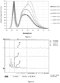
- the figure 1 shows an exemplary plot of optical radiation spectrum of light emitted by a TIG arc. Significant components appear on wavelengths between 300 nm and 500 nm, which falls within ultraviolet (UV) range and visible light.
- Optical radiation spectrum of normal sunlight at sea level has clearly broader bandwidth, extending all way from ultraviolet (UV) to infrared (IR) range, as shown in the figure 2 . Intensity maximum of sunlight is at higher wavelengths than that of the TIG arc emitted light.
- Optical radiation spectrum of an incandescent lamp is rather similar to that of the Sun, with the difference that the peak of the optical radiation spectrum is at about 1000 nm wavelength.
- Spectral power of typical power LEDs used for lighting is illustrated in the figure 3 , with a typical peak power values at about 450 nm range and other range of high-power values in wavelengths above 500 nm.
- TIG arc it is possible to distinguish light of a TIG arc by detecting ultraviolet light at about 350 nm wavelength, in which the TIG arc spectral characteristics differ from spectral powers of all typical ambient light sources.
- suitable and sufficiently reliable, selective light sensors tend to be difficult to find and quite expensive.
- Patent application US20060285330 discloses an automatic darkening filter.
- Patent application US20100265421 discloses an automatic darkening filter apparatus comprising a shutter control system switching between different states in response to a change in intensity of incident light.
- Patent application US20040178326 discloses a microprocessor based automatically dimmable eye protection with interruption prevention.
- An object is to provide an apparatus and a method for automatically activating an auto-darkening LCD element. Preferably, this object should be achieved in energy efficient way.
- the object is to provide an apparatus and a method for automatically activating the auto-darkening LCD element in case of presence of a TIG arc.
- the objects of the present invention are achieved with an apparatus according to claim 1 and a welding helmet or welding mask according to claim 9.
- the objects of the present invention are further achieved with a method according to the claim 10.
- an apparatus comprising an auto-darkening LCD element and circuitry for controlling the auto-darkening LCD element.
- the circuitry comprises a light detector configured to detect intensity of incident light as a function of time and to generate a detection signal on basis of the detected intensity of incident light.
- the circuitry also comprises a signal processing circuitry configured to process the detection signal for generating a silent arc indication signal indicating presence of a silent arc when amplitude of the detection signal in a predetermined frequency range characteristic to a silent arc is above a predetermined threshold value, and wherein a lower limit of the predetermined frequency range is between 300 Hz and 400 Hz.
- the circuitry further comprises an activation circuitry configured to activate darkening of the auto-darkening LCD element when presence of the silent arc is indicated by the silent arc indication signal.
- said signal processing circuitry comprises a high pass filter configured to filter the detection signal, wherein a cut-off frequency of the high pass filter is at a lower limit of said predetermined frequency range that is characteristic to a silent arc, and wherein the cut-off frequency of the high pass filter is higher than a respective frequency range of intensity variation of light emitted by typical ambient light sources, such as incandescent lamps, fluorescent lamps and/or LED lamps, and a comparator configured to compare amplitude of the filtered detection signal to the predetermined threshold value for generating the silent arc indication signal.
- typical ambient light sources such as incandescent lamps, fluorescent lamps and/or LED lamps
- the signal processing circuitry further comprises a low pass filter configured to low pass filter the detection signal, the low pass filter having a cut-off frequency between about 1 kHz and about 3 kHz, or a band pass filter configured to perform both said high pass filtering and said low pass filtering.
- the activation circuitry is further configured to activate darkening of the auto-darkening LCD element upon determining, by the circuitry for controlling the auto-darkening LCD element, presence of incident light with an intensity that exceeds a predetermined intensity threshold.
- the circuitry is configured to have a) an active state, in which the circuitry is active, and the auto-darkening LCD element is darkened, b) a standby state, in which the circuitry is active and capable of activating said darkening of the auto-darkening LCD element within about 0.1 to 1 ms from receiving the indication of presence of the silent arc and upon determining presence of incident light with an intensity that exceeds the predetermined intensity threshold, and c) an idle state, in which at least part of the circuitry is set to a low-power state, in which it consumes less power than in the active state.
- the circuitry further comprises a motion detector, wherein the circuitry is configured to be put from the idle state into the standby state upon detecting, by the motion detector, that amount of movement of the apparatus within a predetermined time period exceeds a predetermined movement threshold value, and wherein the circuitry is configured to be put from the standby state into the idle state upon detecting, by the motion sensor, that amount of movement of the apparatus within the predetermined time period does not exceed the predetermined movement threshold value.
- the circuitry further comprises a voltage multiplier configured to generate a trigger voltage for triggering activation of the auto-darkening LCD element, wherein a) in the standby state of the circuitry, the voltage multiplier is configured to operate periodically for generating the trigger voltage, and the circuitry further comprises at least one capacitor configured to store the trigger voltage temporarily, when the voltage multiplier is off during the periodical trigger voltage generation operation, and b) in the idle state of the circuitry, operation of the voltage multiplier is disabled.
- the circuitry for controlling is implemented using CMOS logic.
- a welding helmet or a welding mask comprising an auto-darkening LCD element and the circuitry for controlling the auto-darkening LCD element according to any one of the preceding claims.
- a method for controlling an auto-darkening LCD element comprising: i) detecting intensity of incident light as a function of time and generating a detection signal on basis of the detected intensity of incident light; ii) processing said detection signal for generating a silent arc indication signal indicating presence of a silent arc when amplitude of the detection signal in a predetermined frequency range characteristic to a silent arc is above a predetermined threshold value, and wherein a lower limit of the predetermined frequency range is between 300 Hz and 400 Hz, and iii) activating darkening of the auto-darkening LCD element when presence of the silent arc is indicated by the silent arc indication signal.
- processing said detection signal comprises high pass filtering the detection signal for extracting a portion of the detection signal that is in a predetermined frequency range that is characteristic to a silent arc, and wherein the predetermined frequency range is above a respective frequency range of intensity variation of light emitted by typical ambient light sources, such as incandescent lamps, fluorescent lamps and/or LED lamps, and comparing amplitude of the filtered detection signal to the predetermined threshold value for generating the silent arc indication signal.
- the method comprises activating said darkening of the auto-darkening LCD element also upon determining presence of incident light with an intensity that exceeds a predetermined intensity threshold.
- the method further comprises setting a circuitry implementing the method into one of: a) an active state, in which the circuitry is active, and the auto-darkening LCD element is darkened, b) a standby state, in which the circuitry is active and capable of activating said darkening of the auto-darkening LCD element within about 0.1 to 1 ms from receiving the indication of presence of the silent arc and upon determining presence of incident light with an intensity that exceeds the predetermined intensity threshold, and c) an idle state, in which at least part of the circuitry is set to a low-power state, in which it consumes less power than in the active state.
- the circuitry is put from the idle state into the standby state upon determining that amount of movement within a predetermined time period exceeds a predetermined movement threshold value, and the circuitry is put from the standby state into the idle state upon detecting that amount of movement of the apparatus within the predetermined time period does not exceed the predetermined movement threshold value.
- the method further comprises generating a trigger voltage for triggering activation of the auto-darkening LCD element, wherein a) in the standby state, the trigger voltage is generated periodically, and the trigger voltage is stored temporarily in at least one capacitor during off periods of the periodical trigger voltage generation operation, and b) in the idle state of the circuitry, no trigger voltage is generated.
- the present invention is based on the idea of utilizing light intensity variation characteristics of a silent TIG arc and/or a silent plasma arc for detecting and indicating presence of the silent TIG arc and/or the silent plasma arc, and using this information for activating darkening of the auto-darkening LCD element.
- This operation can complement traditional activation of the auto-darkening LCD element based on detecting presence of bright incident light and activating the darkening when the detected brightness exceeds a brightness threshold value.
- the present invention has the advantage that it improves reliability of activation of the auto-darkening LCD element and thus improves protection of user's eyes during TIG welding, as well as during PAW and plasma cutting.
- the invention further improves energy efficiency of circuitry used for controlling the auto-darkening LCD element, which consequently increases battery lifetime and thus operation lifetime of the welding helmet or welding mask.
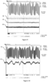
- Figure 4 illustrates characteristics of intensity of light emitted by a silent TIG arc.
- Upper graph (40) illustrates intensity in time domain, in other words as function of time, whereas the lower graph (41) illustrates variation of the intensity in frequency domain.
- Vertical line (42) is in this plot placed at 295 Hz on the lower graph scale, for showing that there is significant variation of the intensity of the silent TIG arc emitted light also at frequencies above 300 Hz.
- Sunlight is known to be stable, with no significant variation in intensity over short time periods. Thus, there are no distinctive frequency components in sunlight intensity.
- the inventors have found that it is possible to distinct light from a silent TIG arc from ambient light by detecting frequency components of variation of intensity of the detected incident light that occurs above about 300 Hz.
- the same principle is also applicable to a plasma arc used in PAW and plasma cutting.
- Ideal solution would be a high-pass filter with sharp cut-off frequency, attenuating any frequencies at or below 300 Hz, and little attenuation from 301 Hz onwards.
- a high-pass filter with 50 to 60 dB attenuation at 100 Hz and with no significant attenuation at 400 Hz or higher is capable of providing enough distinction between intensity variations of incident light by ambient light sources and by the silent arc.
- typical ambient light sources may have characteristic light intensity variation for example on frequencies of 120 Hz, 240 Hz and 360 Hz, in which case the high-pass filter preferably has a cut-off frequency above about 360 Hz.
- One implementation alternative is to replace the high-pass filter with specific band-stop filters at typical frequencies of variation of light intensities of the ambient light sources, i.e. at 100 Hz, 200 Hz and optionally 300 Hz in countries with 50 Hz grid frequency or at 120 Hz, 240 Hz and optionally 360 Hz in countries with 60 Hz grid frequency.
- band pass filters is much more complicated than a simple active high-pass filter, and likely more power consuming.
- FIG. 6 illustrates an exemplary implementation for a circuitry for detecting presence of a silent arc.
- the circuitry includes a light detector (60) that provides a detection signal (160) that corresponds to detected intensity of incident light, and a signal processing circuitry for processing the detection signal (160) for producing a TIG arc indication signal (162) that indicates presence of a TIG arc.
- the detection signal is an electrical signal, but also other types of detection signal may be applicable.
- the light detector (60) preferably operates continuously so that the detection signal provides information on intensity of incident light as a function of time.
- the signal processing circuitry may comprise a high pass filter (61) for filtering out any detection signals with frequencies in ranges typical to ambient light sources, and a comparator (62) for providing a silent arc indication signal (162) indicating whether a silent arc is detected or not.
- a high pass filter (61) for filtering out any detection signals with frequencies in ranges typical to ambient light sources
- a comparator (62) for providing a silent arc indication signal (162) indicating whether a silent arc is detected or not.
- output of the comparator (62) may be considered as a digital signal.
- Cut-off frequency of the high pass filter (61) may be selected to fall at the selected lower limit of the above-mentioned useful frequency range that is particularly characteristic for variation of intensity of light emitted by a silent arc. This is achieved by defining the cut-off frequency of the high pass filter (61) such that it effectively filters frequency components from the detection signal that are typical for ambient light sources, such as LED or incandescent lamp, but passes frequencies that are characteristics to the silent arc.
- the cut-off frequency is about 300 Hz, but any cut-off frequency within the above-mentioned frequency ranges of the useful frequency range may be selected.
- the high pass filter (61) produces a high pass filtered detection signal, which may be further subjected to a low pass filter (not shown) for removing other unwanted frequency components.
- the resulting filtered detection signal (161) comprises frequencies which are characteristic to a variation of intensity of light emitted by a silent arc, but not typical for any common ambient light sources.
- the detection signal (160) may be filtered using a bandpass filter with a pass band suitable for this purpose to produce the filtered detection signal (161).
- the high pass filtered detection signal as such may be used as the detection signal (161).
- the filtered detection signal (161) is then fed to the comparator (62), which compares amplitude of the voltage of the filtered detection signal to a predetermined threshold value. If the amplitude of the filtered detection signal exceeds the predetermined threshold value, the silent arc indication signal (162) at the output of the comparator (62) indicates that a silent arc is detected. If the amplitude is below the predetermined threshold value, it is deemed that no silent arc was detected.
- a comparator outputs a digital type signal with two alternative values. This silent arc indication signal (162) can subsequently be used to control the activation circuitry that activates the auto-darkening LCD element, which can also be referred to as darkening of the auto-darkening LCD element.
- Control circuitry that activates darkening of the auto-darkening LCD element preferably implements hysteresis for avoiding blinking of the auto-darkening LCD element between its "light” and “darkened” states.
- Hysteresis may be implemented for example by introducing a delay for deactivating the auto-darkening LCD element.
- a short break in the silent arc or any other welding or plasma cutting arc does not immediately deactivate the auto-darkening LCD element.
- an about 1 second delay may be applied before it is determined that no more silent arc and/or any other type of welding arc is detected, after which deactivation occurs.
- the circuitry is preferably further configured to detect presence of bright incident light produced by any other type of weld arc and detected by the light detector or a further light detector.
- This kind of circuitries used for detecting presence of a welding arc based on detection of bright incident light are well known in the art and may easily be combined with the invented circuitry for controlling a multi-purpose auto-darkening LCD element.
- signal of the light detector (60) will likely need to be amplified in addition to filtering. Any suitable amplifier circuitry known in the art may be used.
- Figure 7 illustrates one possible, non-limiting implementation example of the circuitry for detecting intensity of incident light and for filtering the detection signal which may be utilized in detecting presence of a silent arc, in particular a silent TIC arc.
- the light detector (60) is implemented with a photodiode for providing the detection signal (160) and the high pass filter (61) is implemented using an active two-stage filter circuitry for providing the filtered detection signal (161). Output of the high pass filter may further be fed through a low-pass filter (not shown) before using a comparator (not shown) for determining whether a silent arc is detected as explained above. Output of the comparator may be used as indicator signal for indicating the presence of the silent arc to circuitry controlling activation of the auto-darkening LCD element.
- Figure 8 illustrates another non-limiting implementation example of the circuitry for detecting intensity of incident light and for filtering the detection signal which may be utilized in detecting presence of a silent arc.
- this high-pass filter (61) circuitry has been designed for power saving.
- Figure 9 illustrates filtered detection signals (161) at the output of the exemplary high pass filter (61) with different types of light emission sources detected by the light detector (60).
- Graph 81 represents a high pass filtered detection signal at the output of the high pass filter (61) obtained on basis of a 10A DC TIG arc operated with an inverter power source.
- Graph 82 represents a correspondingly filtered detection signal obtained on basis of light emitted by a fluorescent lamp
- graph 83 represents a correspondingly filtered detection signal obtained on basis of light emitted by an incandescent lamp
- graph (84) represents a correspondingly filtered detection signal obtained on basis of light emitted by a LED lighting device.
- the graph 81 indicates that the detection signal (81) representing intensity of incident light emitted by the silent arc includes at least one higher frequency component.
- this higher frequency component is caused by an inverter that is used for generating a DC power signal for operating the TIG weld. If such component is produced in the used welding apparatus, the higher frequency component can be further filtered out for example by using a low pass filter that filters out the inverter frequency. Exact inverter frequency to be filtered out is a design option, depending on the source and characteristics of such higher frequency component, such as implementation of inverter apparatus used. In the exemplary system, a low pass filter with a cut-off frequency at about 3 kHz was used.
- TIG welding and in particular a silent TIG arc as an example, the same principle applies to a plasma arc used in PAW or in plasma cutting.
- the auto-darkening LCD element In a standby state the auto-darkening LCD element is not darkened. Energy is consumed by a light detector and an amplifier associated therewith and a control logic. For facilitating quick darkening operation of the auto-darkening LCD element, an about 20V to 30V voltage peak, referred here as a trigger voltage, is fed to the LCD element. There is a need of darkening the auto-darkening LCD element before human eye can actually detect the light emitted by the arc. Thus, activation of the auto-darkening LCD element shall occur within 0.1 ms to 1 ms from time of appearance of the arc. Thus, the trigger voltage shall be available very quickly.
- the trigger voltage is in practice obtained from about 3V to 6V battery carried by the welding helmet or the weld mask, and thus it is not readily available. For enabling fast generation of the trigger voltage, energy is consumed during the standby state.
- the auto-darkening LCD element is dark, only about 2V to 3V voltage is required for maintaining the auto-darkening LCD element in the activated state, in which the LCD element is darkened.
- Energy consumption of the activated, darkened auto-darkening LCD element is higher than in the standby state, since the glass-based LCD element is equivalent to a lossy capacitor, and it requires constant feeding of energy to remain in the active state.
- Typical current consumption of an auto-darkening LCD element in the active state is about 100 ⁇ A-200 ⁇ A, or even more.
- CMOS logic has low standby state current consumption, typically less than 1 ⁇ A. If a processor is used for implementing control logic, it may require up to 100 ⁇ A-200 ⁇ A operating current even in the standby state.
- all power consuming elements of the welding helmet or glasses may be optimized.
- photovoltaic mode also known as the zero-bias mode
- the photodiode produces a voltage when exposed to light.
- Photodiode could also be used in photoconductive mode or in avalanche diode mode, both of which uses reverse biasing, but these modes require generation of the reverse bias voltage, which consumes energy.
- the trigger voltage needs to be generated in advance so that it is readily available when needed.
- a typical energy source available is a 3V to 6V battery, and the trigger voltage may be generated based on the battery voltage with a voltage multiplier.
- Current consumption of a traditional voltage multiplier is in range of hundreds of microamperes. Total power consumption of the voltage multiplier may be reduced for example by operating it periodically.
- voltage multiplier In periodical operation, voltage multiplier only operates periodically. The voltage multiplier operates actively during its active periods, and between the active periods, there are off periods, during which the generated trigger voltage is stored into a capacitor or capacitors from which it is immediately available. Exact periodicity of the periodical trigger voltage generation operation and design and proportioning of the circuitry elements needed are design options.
- a motion sensor may be used for detecting whether the welding helmet or mask is moving, which indicates whether the welding helmet or mask in use or not. If no motion is detected during a predetermined time period, the welding helmet or mask may be put in a deactivated state, which may be also called as an idle state.
- Any known type of motion sensor may be utilized for detecting movement, for example an acceleration sensor or a gyroscope. In practice, an acceleration sensor of any known type is preferred for implementing motion detection.
- the gyroscope although technically equally useful, requires more power and is more expensive.
- the light detector, some parts of the control logic and/or the trigger voltage generation may be deactivated when the welding helmet or mask is not in use, and activated only if the motion sensor detects that the welding helmet moves sufficiently in a predefined period of time.
- the standby state is activated so that the auto-darkening LCD element is ready to be put in active state for protecting eyes of the user.
- arc detection is active, and the auto-darkening LCD element is activated and darkened upon detecting presence of an arc on basis of characteristics of the incident light as explained above.
- the apparatus is put from the standby state to idle state for power saving.
- a common battery of a welding helmet is a lithium battery with total capacity of 200 to 600 mAh.
- Many welding helmets further comprise one or more solar panels as an additional energy source. In normal ambient light, the solar panels typically produce just a little if any energy.
- a well-designed and sufficiently large solar panel may generate several hundreds of microamperes current from the from the incident light energy from the weld arc itself, which may be sufficient to self-produce all energy required for operating the auto-darkening LCD element as well as operation of the circuitry in the welding helmet or mask for controlling and operating it.
- the battery lifetime may be more than one year. With a low power motion sensor, the standby current may be further reduced.
Landscapes
- Health & Medical Sciences (AREA)
- Engineering & Computer Science (AREA)
- Physics & Mathematics (AREA)
- Biomedical Technology (AREA)
- Public Health (AREA)
- Optics & Photonics (AREA)
- Nonlinear Science (AREA)
- Mechanical Engineering (AREA)
- Veterinary Medicine (AREA)
- Ophthalmology & Optometry (AREA)
- General Health & Medical Sciences (AREA)
- Heart & Thoracic Surgery (AREA)
- Vascular Medicine (AREA)
- Life Sciences & Earth Sciences (AREA)
- Animal Behavior & Ethology (AREA)
- Chemical & Material Sciences (AREA)
- General Physics & Mathematics (AREA)
- Crystallography & Structural Chemistry (AREA)
- Plasma & Fusion (AREA)
- Liquid Crystal (AREA)
- Liquid Crystal Display Device Control (AREA)
Claims (15)
- Vorrichtung umfassend ein selbstverdunkelndes LCD-Element und eine Schaltungsanordnung zur Ansteuerung des selbstverdunkelnden LCD-Elements, wobei ein ruhiger Lichtbogen eine Situation bezeichnet, in der die Intensität von Licht, das von einem beim TIG-Schweißen, Plasmalichtbogenschweißen oder Plasmaschneiden verwendeten Lichtbogen emittiert wird, besonders stet ist, wobei die Schaltungsanordnung umfasst:- einen Lichtdetektor (60), der dazu ausgelegt ist, die Intensität von einfallendem Licht in Abhängigkeit von der Zeit zu detektieren und ein Detektionssignal (160) basierend auf der detektierten Intensität des einfallenden Lichts zu erzeugen,gekennzeichnet dadurch, dass die Schaltungsanordnung umfasst:- eine Signalverarbeitungsschaltung (61, 62), die ausgelegt ist zum Verarbeiten des Detektionssignals (160) zur Erzeugung eines Ruhig-Lichtbogen-Anzeigesignals (162), das das Vorliegen eines ruhigen Lichtbogens anzeigt, wenn die Amplitudenschwankung des Detektionssignals (160) in einem für den ruhigen Lichtbogen charakteristischen vorherbestimmten Frequenzbereich einen vorherbestimmten Schwellwert übersteigt, und wobei eine Untergrenze des vorherbestimmten Frequenzbereichs zwischen 300 Hz und 400 Hz beträgt, und- eine Aktivierungsschaltung, die dazu ausgelegt ist, das Verdunkeln des selbstverdunkelnden LCD-Elements zu aktivieren, wenn vom Ruhig-Lichtbogen-Anzeigesignal (162) das Vorliegen des ruhigen Lichtbogens angezeigt wird.
- Vorrichtung nach Anspruch 1, wobei die Signalverarbeitungsschaltung (61, 62) umfasst:- ein Hochpassfilter (61), das zum Filtern des Detektionssignals (160) ausgelegt ist, wobei eine Grenzfrequenz des Hochpassfilters (61) an einer Untergrenze des für einen ruhigen Lichtbogen charakteristischen vorherbestimmten Frequenzbereichs liegt, und wobei die Grenzfrequenz des Hochpassfilters (61) höher ist als ein entsprechender Frequenzbereich der Intensitätsschwankung eines von typischen Umgebungslichtquellen, wie von Glühlampen, fluoreszierenden Lampen und/oder LED-Lampen, emittierten Lichts, und- einen Vergleicher (62), der dazu ausgelegt ist, die Amplitude des gefilterten Detektionssignals (161) mit dem vorherbestimmten Schwellwert zu vergleichen, um das Ruhig-Lichtbogen-Anzeigesignal zu erzeugen.
- Vorrichtung nach Anspruch 1 oder 2, wobei die Signalverarbeitungsschaltung ferner umfasst: ein Tiefpassfilter, das zur Tiefpassfilterung des Detektionssignals ausgelegt ist, wobei das Tiefpassfilter eine Grenzfrequenz zwischen etwa 1 kHz und etwa 3 kHz aufweist, oder ein Bandpassfilter, das zur Ausführung sowohl der Hochpassfilterung als auch der Tiefpassfilterung ausgelegt ist.
- Vorrichtung nach einem der vorhergehenden Ansprüche, wobei die Aktivierungsschaltung ferner dazu ausgelegt ist, das Verdunkeln des selbstverdunkelnden LCD-Elements zu aktivieren, wenn von der Schaltung zur Ansteuerung des selbstverdunkelnden LCD-Elements das Vorliegen von einfallendem Licht mit einer eine vorherbestimmte Intensitätsschwelle überschreitenden Intensität festgestellt wird.
- Vorrichtung nach einem der vorhergehenden Ansprüche, wobei die Schaltungsanordnung so ausgelegt ist, dass sie Folgendes aufweist:a) einen Aktiv-Zustand, in dem die Schaltungsanordnung aktiv ist und das selbstverdunkelnde LCD-Element verdunkelt wird,b) einen Standby-Zustand, in dem die Schaltungsanordnung aktiv und in der Lage ist, die Verdunkelung des selbstverdunkelnden LCD-Elements binnen etwa 0,1 bis 1 ms nach Empfang der Anzeige über das Vorliegen des ruhigen Lichtbogens und, in Abhängigkeit von Anspruch 4, bei Feststellung des Vorliegens von einfallendem Licht mit einer die vorherbestimmte Intensitätsschwelle übersteigenden Intensität, zu aktivieren, undc) einen Ruhezustand, in dem die Schaltungsanordnung mindestens zum Teil in einen stromsparenden Zustand versetzt wird, in dem sie weniger Strom als im Aktiv-Zustand verbraucht.
- Vorrichtung nach Anspruch 5, wobei die Schaltungsanordnung ferner einen Bewegungsdetektor umfasst, wobei die Schaltungsanordnung so ausgelegt ist, dass sie vom Ruhezustand in den Standby-Zustand versetzt wird, wenn vom Bewegungsdetektor detektiert wird, dass der Bewegungsbetrag der Vorrichtung innerhalb einer vorherbestimmten Zeitperiode einen vorherbestimmten Bewegungsschwellwert überschreitet, und wobei die Schaltungsanordnung so ausgelegt ist, dass sie vom Standby-Zustand in den Ruhezustand versetzt wird, wenn vom Bewegungsdetector detektiert wird, dass der Bewegungsbetrag der Vorrichtung innerhalb der vorherbestimmten Zeitperiode den vorherbestimmten Bewegungsschwellwert nicht überschreitet.
- Vorrichtung nach einem der Ansprüche 5 bis 6, wobei die Schaltungsanordnung ferner einen Spannungsvervielfacher umfasst, der dazu ausgelegt ist, eine Triggerspannung zur Auslösung der Aktivierung des selbstverdunkelnden LCD-Elements zu erzeugen, wobeia) im Standby-Zustand der Schaltungsanordnung der Spannungsvervielfacher für einen periodischen Betrieb ausgelegt ist, um die Triggerspannung zu erzeugen, und die Schaltungsanordnung ferner mindestens einen Kondensator umfasst, der für eine temporäre Speicherung der Triggerspannung ausgelegt ist, wenn der Spannungsvervielfacher während des periodischen Triggerspannungserzeugungsbetriebs ausgeschaltet ist, undb) im Ruhezustand der Schaltungsanordnung der Betrieb des Spannungsvervielfachers deaktiviert ist.
- Schweißhelm oder Schweißmaske umfassend ein selbstverdunkelndes LCD-Element und die Schaltungsanordnung zur Ansteuerung des selbstverdunkelnden LCD-Elements nach einem der vorhergehenden Ansprüche.
- Verfahren zur Ansteuerung eines selbstverdunkelndes LCD-Elements, wobei ein ruhiger Lichtbogen eine Situation bezeichnet, in der die Intensität des Lichts, das von einem beim TIG-Schweißen, Plasmalichtbogenschweißen oder Plasmaschneiden verwendeten Lichtbogen emittiert wird, besonders stet ist, wobei das Verfahren umfasst:- Detektieren der Intensität von einfallendem Licht in Abhängigkeit von der Zeit und Erzeugen eines Detektionssignals (160) basierend auf der detektierten Intensität des einfallenden Lichts;gekennzeichnet dadurch, dass das Verfahren umfasst:- Verarbeiten des Detektionssignals (160) zur Erzeugung eines Ruhig-Lichtbogen-Anzeigesignals (162), das das Vorliegen eines ruhigen Lichtbogens anzeigt, wenn die Amplitudenschwankung des Detektionssignals (160) in einem für einen ruhigen Lichtbogen charakteristischen vorherbestimmten Frequenzbereich einen vorherbestimmten Schwellwert übersteigt, und wobei eine Untergrenze des vorherbestimmten Frequenzbereichs zwischen 300 Hz und 400 Hz beträgt, und- Aktivieren der Verdunkelung des selbstverdunkelnden LCD-Elements, wenn vom Ruhig-Lichtbogen-Anzeigesignal (162) das Vorliegen des ruhigen Lichtbogens angezeigt wird.
- Verfahren nach Anspruch 9, wobei das Verarbeiten des Detektionssignals (160) umfasst:- Hochpassfiltern des Detektionssignals zur Extraktion eines Teils des Detektionssignals, der in einem für einen ruhigen Lichtbogen charakteristischen vorherbestimmten Frequenzbereich liegt, und wobei der vorherbestimmte Frequenzbereich oberhalb eines entsprechenden Frequenzbereichs der Intensitätsschwankung eines von typischen Umgebungslichtquellen, wie von Glühlampen, fluoreszierenden Lampen und/oder LED-Lampen emittierten Lichts liegt, und- Vergleichen der Amplitude des gefilterten Detektionssignals (161) mit dem vorherbestimmten Schwellwert zur Erzeugung des Ruhig-Lichtbogen-Anzeigesignals (162).
- Verfahren nach Anspruch 9 oder 10, ferner umfassend: Tiefpassfiltern des Detektionssignals, wobei die Tiefpassfilterung die Obergrenze des vorherbestimmten Frequenzbereichs definiert, wobei die Obergrenze zwischen etwa 1 kHz und etwa 3 kHz beträgt.
- Verfahren nach einem der Ansprüche 9 bis 12, ferner umfassend: Aktivieren der Verdunkelung des selbstverdunkelnden LCD-Elements auch bei Feststellung des Vorliegens eines einfallenden Lichts mit einer eine vorherbestimmte Intensitätsschwelle überschreitenden Intensität.
- Verfahren nach einem der Ansprüche 9 bis 13, ferner umfassend: Setzen einer das Verfahren implementierenden Schaltungsanordnung in einen der folgenden Zustände:a) einen Aktiv-Zustand, in dem die Schaltungsanordnung aktiv ist und das selbstverdunkelnde LCD-Element abgedunkelt wird,b) einen Standby-Zustand, in dem die Schaltungsanordnung aktiv und in der Lage ist, die Verdunkelung des selbstverdunkelnden LCD-Elements binnen etwa 0,1 bis 1 ms nach Empfang der Anzeige über das Vorliegen des ruhigen Lichtbogens und, in Abhängigkeit von Anspruch 12, bei Feststellung des Vorliegens von einfallendem Licht mit einer die vorherbestimmte Intensitätsschwelle übersteigenden Intensität, zu aktivieren, undc) einen Ruhezustand, in dem die Schaltungsanordnung mindestens zum Teil in einen stromsparenden Zustand versetzt wird, in dem sie weniger Strom als im Aktiv-Zustand verbraucht.
- Verfahren nach Anspruch 13, wobei die Schaltungsanordnung vom Ruhezustand in den Standby-Zustand versetzt wird, wenn festgestellt wird, dass der Bewegungsbetrag innerhalb einer vorherbestimmten Zeitperiode einen vorherbestimmten Bewegungsschwellwert überschreitet, und die Schaltungsanordnung vom Standby-Zustand in den Ruhezustand versetzt wird, wenn detektiert wird, dass der Bewegungsbetrag der Vorrichtung innerhalb der vorherbestimmten Zeitperiode den vorherbestimmten Bewegungsschwellwert nicht überschreitet.
- Verfahren nach einem der Ansprüche 13 bis 14, wobei das Verfahren ferner das Erzeugen einer Triggerspannung zur Auslösung der Aktivierung des selbstverdunkelnden LCD-Elements umfasst, wobeia) im Standby-Zustand die Triggerspannung periodisch erzeugt wird und die Triggerspannung während Ausschaltperioden des periodischen Triggerspannungserzeugungsbetriebs in mindestens einem Kondensator temporär gespeichert wird, undb) im Ruhezustand der Schaltungsanordnung keine Triggerspannung erzeugt wird.
Applications Claiming Priority (2)
| Application Number | Priority Date | Filing Date | Title |
|---|---|---|---|
| FI20206025A FI129978B (fi) | 2020-10-19 | 2020-10-19 | Automaattisesti tummeneva lcd-suodatinlasielementti |
| PCT/FI2021/050591 WO2022084577A1 (en) | 2020-10-19 | 2021-09-02 | Auto-darkening lcd filter glass element |
Publications (3)
| Publication Number | Publication Date |
|---|---|
| EP4045220A1 EP4045220A1 (de) | 2022-08-24 |
| EP4045220C0 EP4045220C0 (de) | 2024-01-03 |
| EP4045220B1 true EP4045220B1 (de) | 2024-01-03 |
Family
ID=77774938
Family Applications (1)
| Application Number | Title | Priority Date | Filing Date |
|---|---|---|---|
| EP21770288.5A Active EP4045220B1 (de) | 2020-10-19 | 2021-09-02 | Automatisch verdunkelndes lcd-filterglaselement |
Country Status (5)
| Country | Link |
|---|---|
| EP (1) | EP4045220B1 (de) |
| CN (1) | CN114901415B (de) |
| AU (1) | AU2021363658B2 (de) |
| FI (1) | FI129978B (de) |
| WO (1) | WO2022084577A1 (de) |
Family Cites Families (7)
| Publication number | Priority date | Publication date | Assignee | Title |
|---|---|---|---|---|
| EP0331861A1 (de) * | 1988-03-11 | 1989-09-13 | Optrel Ag | Vorrichtung zur Steuerung der Transmission eines Lichtschutzfilters |
| US5252817A (en) * | 1991-03-25 | 1993-10-12 | Osd Envizion Company | Detector system for detecting the occurrence of welding using detector feedback |
| US5248880A (en) * | 1991-03-25 | 1993-09-28 | Osd Envizion Company | Detector system for detecting the occurrence of welding |
| WO2000062119A1 (en) * | 1999-04-09 | 2000-10-19 | Jackson Products, Inc. | Welding helmet with hybrid lens system and low power consumption control circuit therefor |
| EP1118899A1 (de) * | 2000-01-20 | 2001-07-25 | Jean-Claude Dumas | Optische Vorrichtung mit einem automatisch als Funktion des einfallenden Lichts gesteuerten elektrooptischen Filter |
| US6841772B1 (en) * | 2001-05-05 | 2005-01-11 | Jackson Products, Inc. | Eye-protection device having dual high voltage switching |
| US10663779B1 (en) * | 2019-07-10 | 2020-05-26 | Arcmask Optech Co., Ltd. | Welding helmet with single LCD filter lens |
-
2020
- 2020-10-19 FI FI20206025A patent/FI129978B/fi active
-
2021
- 2021-09-02 AU AU2021363658A patent/AU2021363658B2/en active Active
- 2021-09-02 CN CN202180008084.1A patent/CN114901415B/zh active Active
- 2021-09-02 WO PCT/FI2021/050591 patent/WO2022084577A1/en not_active Ceased
- 2021-09-02 EP EP21770288.5A patent/EP4045220B1/de active Active
Also Published As
| Publication number | Publication date |
|---|---|
| FI129978B (fi) | 2022-12-15 |
| WO2022084577A1 (en) | 2022-04-28 |
| CN114901415A (zh) | 2022-08-12 |
| FI20206025A1 (en) | 2022-04-20 |
| EP4045220C0 (de) | 2024-01-03 |
| CN114901415B (zh) | 2025-11-18 |
| AU2021363658B2 (en) | 2026-04-02 |
| EP4045220A1 (de) | 2022-08-24 |
| AU2021363658A1 (en) | 2022-06-16 |
Similar Documents
| Publication | Publication Date | Title |
|---|---|---|
| RU2385699C2 (ru) | Автоматический затемняющий фильтр с автоматическим управлением питания | |
| KR100213581B1 (ko) | 눈보호 및 고속 셔터링을 위한 전자액정렌즈 드라이버 | |
| US5315099A (en) | Glare shielding device and process for operating same | |
| KR100290543B1 (ko) | 온도 보상 눈부심 방지장치 및 그 방법 | |
| CN101853639B (zh) | 功能显示型防眩目设备 | |
| US8599323B2 (en) | Battery low-voltage warning apparatus for auto-darkening filter for welding helmet | |
| JPH01234820A (ja) | 電気光学的溶接用レンズアセンブリ | |
| WO1993013397A1 (en) | Welding arc light detector for use with electronic for eye protection and high speed shuttering | |
| US6552316B1 (en) | Glare protecting device utilizing both optical and non-optical detectors and method of controlling thereof | |
| US7564014B2 (en) | Apparatus for detecting welding light and protecting eyes from glare and method for controlling the same | |
| US5444232A (en) | Antiglare device to protect eyes during welding and immediately thereafter for a time based on the intensity and duration of the welding light | |
| US20140063377A1 (en) | AntiGlare Device | |
| US20070152132A1 (en) | Apparatus for detecting electromagnetic wave and protecting eyes from glare | |
| EP4045220B1 (de) | Automatisch verdunkelndes lcd-filterglaselement | |
| US20140001343A1 (en) | Antiglare apparatus having a self-diagnosis mode | |
| US20140021337A1 (en) | Multifunctional digital antiglare device | |
| US8368318B2 (en) | Pocket tool with a light pointer | |
| KR100280967B1 (ko) | 눈부심 방지장치 및 그 제어방법 | |
| US10663779B1 (en) | Welding helmet with single LCD filter lens | |
| CN106974763A (zh) | 无线自动变光面罩 | |
| KR0134971Y1 (ko) | 용접용 lcd 차폐경장치 | |
| CN103759821A (zh) | 紫外线探测器 | |
| CN108904130B (zh) | 电焊镜 | |
| KR970005719Y1 (ko) | 용접용 보안면의 광감지회로 | |
| JP2015041210A (ja) | 警報器 |
Legal Events
| Date | Code | Title | Description |
|---|---|---|---|
| STAA | Information on the status of an ep patent application or granted ep patent |
Free format text: STATUS: UNKNOWN |
|
| STAA | Information on the status of an ep patent application or granted ep patent |
Free format text: STATUS: THE INTERNATIONAL PUBLICATION HAS BEEN MADE |
|
| PUAI | Public reference made under article 153(3) epc to a published international application that has entered the european phase |
Free format text: ORIGINAL CODE: 0009012 |
|
| STAA | Information on the status of an ep patent application or granted ep patent |
Free format text: STATUS: REQUEST FOR EXAMINATION WAS MADE |
|
| 17P | Request for examination filed |
Effective date: 20220516 |
|
| AK | Designated contracting states |
Kind code of ref document: A1 Designated state(s): AL AT BE BG CH CY CZ DE DK EE ES FI FR GB GR HR HU IE IS IT LI LT LU LV MC MK MT NL NO PL PT RO RS SE SI SK SM TR |
|
| GRAP | Despatch of communication of intention to grant a patent |
Free format text: ORIGINAL CODE: EPIDOSNIGR1 |
|
| STAA | Information on the status of an ep patent application or granted ep patent |
Free format text: STATUS: GRANT OF PATENT IS INTENDED |
|
| P01 | Opt-out of the competence of the unified patent court (upc) registered |
Effective date: 20230526 |
|
| INTG | Intention to grant announced |
Effective date: 20230615 |
|
| GRAJ | Information related to disapproval of communication of intention to grant by the applicant or resumption of examination proceedings by the epo deleted |
Free format text: ORIGINAL CODE: EPIDOSDIGR1 |
|
| STAA | Information on the status of an ep patent application or granted ep patent |
Free format text: STATUS: REQUEST FOR EXAMINATION WAS MADE |
|
| INTC | Intention to grant announced (deleted) | ||
| GRAP | Despatch of communication of intention to grant a patent |
Free format text: ORIGINAL CODE: EPIDOSNIGR1 |
|
| STAA | Information on the status of an ep patent application or granted ep patent |
Free format text: STATUS: GRANT OF PATENT IS INTENDED |
|
| GRAS | Grant fee paid |
Free format text: ORIGINAL CODE: EPIDOSNIGR3 |
|
| INTG | Intention to grant announced |
Effective date: 20231027 |
|
| GRAA | (expected) grant |
Free format text: ORIGINAL CODE: 0009210 |
|
| STAA | Information on the status of an ep patent application or granted ep patent |
Free format text: STATUS: THE PATENT HAS BEEN GRANTED |
|
| AK | Designated contracting states |
Kind code of ref document: B1 Designated state(s): AL AT BE BG CH CY CZ DE DK EE ES FI FR GB GR HR HU IE IS IT LI LT LU LV MC MK MT NL NO PL PT RO RS SE SI SK SM TR |
|
| DAV | Request for validation of the european patent (deleted) | ||
| DAX | Request for extension of the european patent (deleted) | ||
| REG | Reference to a national code |
Ref country code: GB Ref legal event code: FG4D |
|
| REG | Reference to a national code |
Ref country code: CH Ref legal event code: EP |
|
| REG | Reference to a national code |
Ref country code: DE Ref legal event code: R096 Ref document number: 602021008387 Country of ref document: DE |
|
| REG | Reference to a national code |
Ref country code: IE Ref legal event code: FG4D |
|
| U01 | Request for unitary effect filed |
Effective date: 20240109 |
|
| U07 | Unitary effect registered |
Designated state(s): AT BE BG DE DK EE FI FR IT LT LU LV MT NL PT SE SI Effective date: 20240116 |
|
| REG | Reference to a national code |
Ref country code: NO Ref legal event code: T2 Effective date: 20240103 |
|
| P04 | Withdrawal of opt-out of the competence of the unified patent court (upc) registered |
Effective date: 20240112 |
|
| PG25 | Lapsed in a contracting state [announced via postgrant information from national office to epo] |
Ref country code: ES Free format text: LAPSE BECAUSE OF FAILURE TO SUBMIT A TRANSLATION OF THE DESCRIPTION OR TO PAY THE FEE WITHIN THE PRESCRIBED TIME-LIMIT Effective date: 20240103 |
|
| PG25 | Lapsed in a contracting state [announced via postgrant information from national office to epo] |
Ref country code: ES Free format text: LAPSE BECAUSE OF FAILURE TO SUBMIT A TRANSLATION OF THE DESCRIPTION OR TO PAY THE FEE WITHIN THE PRESCRIBED TIME-LIMIT Effective date: 20240103 |
|
| PG25 | Lapsed in a contracting state [announced via postgrant information from national office to epo] |
Ref country code: IS Free format text: LAPSE BECAUSE OF FAILURE TO SUBMIT A TRANSLATION OF THE DESCRIPTION OR TO PAY THE FEE WITHIN THE PRESCRIBED TIME-LIMIT Effective date: 20240503 |
|
| PG25 | Lapsed in a contracting state [announced via postgrant information from national office to epo] |
Ref country code: GR Free format text: LAPSE BECAUSE OF FAILURE TO SUBMIT A TRANSLATION OF THE DESCRIPTION OR TO PAY THE FEE WITHIN THE PRESCRIBED TIME-LIMIT Effective date: 20240404 |
|
| PG25 | Lapsed in a contracting state [announced via postgrant information from national office to epo] |
Ref country code: HR Free format text: LAPSE BECAUSE OF FAILURE TO SUBMIT A TRANSLATION OF THE DESCRIPTION OR TO PAY THE FEE WITHIN THE PRESCRIBED TIME-LIMIT Effective date: 20240103 Ref country code: RS Free format text: LAPSE BECAUSE OF FAILURE TO SUBMIT A TRANSLATION OF THE DESCRIPTION OR TO PAY THE FEE WITHIN THE PRESCRIBED TIME-LIMIT Effective date: 20240403 |
|
| PG25 | Lapsed in a contracting state [announced via postgrant information from national office to epo] |
Ref country code: CZ Free format text: LAPSE BECAUSE OF FAILURE TO SUBMIT A TRANSLATION OF THE DESCRIPTION OR TO PAY THE FEE WITHIN THE PRESCRIBED TIME-LIMIT Effective date: 20240103 |
|
| PG25 | Lapsed in a contracting state [announced via postgrant information from national office to epo] |
Ref country code: RS Free format text: LAPSE BECAUSE OF FAILURE TO SUBMIT A TRANSLATION OF THE DESCRIPTION OR TO PAY THE FEE WITHIN THE PRESCRIBED TIME-LIMIT Effective date: 20240403 Ref country code: IS Free format text: LAPSE BECAUSE OF FAILURE TO SUBMIT A TRANSLATION OF THE DESCRIPTION OR TO PAY THE FEE WITHIN THE PRESCRIBED TIME-LIMIT Effective date: 20240503 Ref country code: HR Free format text: LAPSE BECAUSE OF FAILURE TO SUBMIT A TRANSLATION OF THE DESCRIPTION OR TO PAY THE FEE WITHIN THE PRESCRIBED TIME-LIMIT Effective date: 20240103 Ref country code: GR Free format text: LAPSE BECAUSE OF FAILURE TO SUBMIT A TRANSLATION OF THE DESCRIPTION OR TO PAY THE FEE WITHIN THE PRESCRIBED TIME-LIMIT Effective date: 20240404 Ref country code: CZ Free format text: LAPSE BECAUSE OF FAILURE TO SUBMIT A TRANSLATION OF THE DESCRIPTION OR TO PAY THE FEE WITHIN THE PRESCRIBED TIME-LIMIT Effective date: 20240103 |
|
| PG25 | Lapsed in a contracting state [announced via postgrant information from national office to epo] |
Ref country code: PL Free format text: LAPSE BECAUSE OF FAILURE TO SUBMIT A TRANSLATION OF THE DESCRIPTION OR TO PAY THE FEE WITHIN THE PRESCRIBED TIME-LIMIT Effective date: 20240103 |
|
| PG25 | Lapsed in a contracting state [announced via postgrant information from national office to epo] |
Ref country code: PL Free format text: LAPSE BECAUSE OF FAILURE TO SUBMIT A TRANSLATION OF THE DESCRIPTION OR TO PAY THE FEE WITHIN THE PRESCRIBED TIME-LIMIT Effective date: 20240103 |
|
| REG | Reference to a national code |
Ref country code: DE Ref legal event code: R097 Ref document number: 602021008387 Country of ref document: DE |
|
| PG25 | Lapsed in a contracting state [announced via postgrant information from national office to epo] |
Ref country code: SM Free format text: LAPSE BECAUSE OF FAILURE TO SUBMIT A TRANSLATION OF THE DESCRIPTION OR TO PAY THE FEE WITHIN THE PRESCRIBED TIME-LIMIT Effective date: 20240103 |
|
| U20 | Renewal fee for the european patent with unitary effect paid |
Year of fee payment: 4 Effective date: 20240916 |
|
| PG25 | Lapsed in a contracting state [announced via postgrant information from national office to epo] |
Ref country code: SK Free format text: LAPSE BECAUSE OF FAILURE TO SUBMIT A TRANSLATION OF THE DESCRIPTION OR TO PAY THE FEE WITHIN THE PRESCRIBED TIME-LIMIT Effective date: 20240103 |
|
| PG25 | Lapsed in a contracting state [announced via postgrant information from national office to epo] |
Ref country code: SM Free format text: LAPSE BECAUSE OF FAILURE TO SUBMIT A TRANSLATION OF THE DESCRIPTION OR TO PAY THE FEE WITHIN THE PRESCRIBED TIME-LIMIT Effective date: 20240103 Ref country code: SK Free format text: LAPSE BECAUSE OF FAILURE TO SUBMIT A TRANSLATION OF THE DESCRIPTION OR TO PAY THE FEE WITHIN THE PRESCRIBED TIME-LIMIT Effective date: 20240103 Ref country code: RO Free format text: LAPSE BECAUSE OF FAILURE TO SUBMIT A TRANSLATION OF THE DESCRIPTION OR TO PAY THE FEE WITHIN THE PRESCRIBED TIME-LIMIT Effective date: 20240103 |
|
| PLBE | No opposition filed within time limit |
Free format text: ORIGINAL CODE: 0009261 |
|
| STAA | Information on the status of an ep patent application or granted ep patent |
Free format text: STATUS: NO OPPOSITION FILED WITHIN TIME LIMIT |
|
| 26N | No opposition filed |
Effective date: 20241007 |
|
| P05 | Withdrawal of opt-out of the competence of the unified patent court (upc) changed |
Free format text: CASE NUMBER: APP_1717/2024 Effective date: 20240116 |
|
| PG25 | Lapsed in a contracting state [announced via postgrant information from national office to epo] |
Ref country code: MC Free format text: LAPSE BECAUSE OF FAILURE TO SUBMIT A TRANSLATION OF THE DESCRIPTION OR TO PAY THE FEE WITHIN THE PRESCRIBED TIME-LIMIT Effective date: 20240103 |
|
| PG25 | Lapsed in a contracting state [announced via postgrant information from national office to epo] |
Ref country code: IE Free format text: LAPSE BECAUSE OF NON-PAYMENT OF DUE FEES Effective date: 20240902 |
|
| REG | Reference to a national code |
Ref country code: CH Ref legal event code: U11 Free format text: ST27 STATUS EVENT CODE: U-0-0-U10-U11 (AS PROVIDED BY THE NATIONAL OFFICE) Effective date: 20251001 |
|
| PGFP | Annual fee paid to national office [announced via postgrant information from national office to epo] |
Ref country code: NO Payment date: 20250922 Year of fee payment: 5 |
|
| PGFP | Annual fee paid to national office [announced via postgrant information from national office to epo] |
Ref country code: GB Payment date: 20250916 Year of fee payment: 5 |
|
| U20 | Renewal fee for the european patent with unitary effect paid |
Year of fee payment: 5 Effective date: 20250916 |
|
| PGFP | Annual fee paid to national office [announced via postgrant information from national office to epo] |
Ref country code: CH Payment date: 20251001 Year of fee payment: 5 |
|
| PG25 | Lapsed in a contracting state [announced via postgrant information from national office to epo] |
Ref country code: CY Free format text: LAPSE BECAUSE OF FAILURE TO SUBMIT A TRANSLATION OF THE DESCRIPTION OR TO PAY THE FEE WITHIN THE PRESCRIBED TIME-LIMIT; INVALID AB INITIO Effective date: 20210902 |
|
| PG25 | Lapsed in a contracting state [announced via postgrant information from national office to epo] |
Ref country code: HU Free format text: LAPSE BECAUSE OF FAILURE TO SUBMIT A TRANSLATION OF THE DESCRIPTION OR TO PAY THE FEE WITHIN THE PRESCRIBED TIME-LIMIT; INVALID AB INITIO Effective date: 20210902 |