EP4044904B1 - Sensorbestimmung - Google Patents
Sensorbestimmung Download PDFInfo
- Publication number
- EP4044904B1 EP4044904B1 EP20797863.6A EP20797863A EP4044904B1 EP 4044904 B1 EP4044904 B1 EP 4044904B1 EP 20797863 A EP20797863 A EP 20797863A EP 4044904 B1 EP4044904 B1 EP 4044904B1
- Authority
- EP
- European Patent Office
- Prior art keywords
- joint
- sensor
- angle
- sensors
- relative
- Prior art date
- Legal status (The legal status is an assumption and is not a legal conclusion. Google has not performed a legal analysis and makes no representation as to the accuracy of the status listed.)
- Active
Links
Images



Classifications
-
- A—HUMAN NECESSITIES
- A61—MEDICAL OR VETERINARY SCIENCE; HYGIENE
- A61B—DIAGNOSIS; SURGERY; IDENTIFICATION
- A61B5/00—Measuring for diagnostic purposes; Identification of persons
- A61B5/68—Arrangements of detecting, measuring or recording means, e.g. sensors, in relation to patient
- A61B5/6801—Arrangements of detecting, measuring or recording means, e.g. sensors, in relation to patient specially adapted to be attached to or worn on the body surface
- A61B5/6813—Specially adapted to be attached to a specific body part
- A61B5/6824—Arm or wrist
-
- A—HUMAN NECESSITIES
- A61—MEDICAL OR VETERINARY SCIENCE; HYGIENE
- A61B—DIAGNOSIS; SURGERY; IDENTIFICATION
- A61B5/00—Measuring for diagnostic purposes; Identification of persons
- A61B5/103—Measuring devices for testing the shape, pattern, colour, size or movement of the body or parts thereof, for diagnostic purposes
- A61B5/107—Measuring physical dimensions, e.g. size of the entire body or parts thereof
- A61B5/1071—Measuring physical dimensions, e.g. size of the entire body or parts thereof measuring angles, e.g. using goniometers
-
- A—HUMAN NECESSITIES
- A61—MEDICAL OR VETERINARY SCIENCE; HYGIENE
- A61B—DIAGNOSIS; SURGERY; IDENTIFICATION
- A61B5/00—Measuring for diagnostic purposes; Identification of persons
- A61B5/103—Measuring devices for testing the shape, pattern, colour, size or movement of the body or parts thereof, for diagnostic purposes
- A61B5/11—Measuring movement of the entire body or parts thereof, e.g. head or hand tremor or mobility of a limb
- A61B5/1121—Determining geometric values, e.g. centre of rotation or angular range of movement
-
- A—HUMAN NECESSITIES
- A61—MEDICAL OR VETERINARY SCIENCE; HYGIENE
- A61B—DIAGNOSIS; SURGERY; IDENTIFICATION
- A61B5/00—Measuring for diagnostic purposes; Identification of persons
- A61B5/103—Measuring devices for testing the shape, pattern, colour, size or movement of the body or parts thereof, for diagnostic purposes
- A61B5/11—Measuring movement of the entire body or parts thereof, e.g. head or hand tremor or mobility of a limb
- A61B5/1113—Local tracking of patients, e.g. in a hospital or private home
- A61B5/1114—Tracking parts of the body
-
- A—HUMAN NECESSITIES
- A61—MEDICAL OR VETERINARY SCIENCE; HYGIENE
- A61B—DIAGNOSIS; SURGERY; IDENTIFICATION
- A61B5/00—Measuring for diagnostic purposes; Identification of persons
- A61B5/45—For evaluating or diagnosing the musculoskeletal system or teeth
- A61B5/4528—Joints
-
- A—HUMAN NECESSITIES
- A61—MEDICAL OR VETERINARY SCIENCE; HYGIENE
- A61B—DIAGNOSIS; SURGERY; IDENTIFICATION
- A61B5/00—Measuring for diagnostic purposes; Identification of persons
- A61B5/68—Arrangements of detecting, measuring or recording means, e.g. sensors, in relation to patient
- A61B5/6801—Arrangements of detecting, measuring or recording means, e.g. sensors, in relation to patient specially adapted to be attached to or worn on the body surface
- A61B5/6813—Specially adapted to be attached to a specific body part
-
- A—HUMAN NECESSITIES
- A61—MEDICAL OR VETERINARY SCIENCE; HYGIENE
- A61B—DIAGNOSIS; SURGERY; IDENTIFICATION
- A61B5/00—Measuring for diagnostic purposes; Identification of persons
- A61B5/68—Arrangements of detecting, measuring or recording means, e.g. sensors, in relation to patient
- A61B5/6801—Arrangements of detecting, measuring or recording means, e.g. sensors, in relation to patient specially adapted to be attached to or worn on the body surface
- A61B5/6813—Specially adapted to be attached to a specific body part
- A61B5/6828—Leg
-
- A—HUMAN NECESSITIES
- A61—MEDICAL OR VETERINARY SCIENCE; HYGIENE
- A61B—DIAGNOSIS; SURGERY; IDENTIFICATION
- A61B5/00—Measuring for diagnostic purposes; Identification of persons
- A61B5/68—Arrangements of detecting, measuring or recording means, e.g. sensors, in relation to patient
- A61B5/6801—Arrangements of detecting, measuring or recording means, e.g. sensors, in relation to patient specially adapted to be attached to or worn on the body surface
- A61B5/6813—Specially adapted to be attached to a specific body part
- A61B5/6829—Foot or ankle
-
- A—HUMAN NECESSITIES
- A61—MEDICAL OR VETERINARY SCIENCE; HYGIENE
- A61B—DIAGNOSIS; SURGERY; IDENTIFICATION
- A61B5/00—Measuring for diagnostic purposes; Identification of persons
- A61B5/72—Signal processing specially adapted for physiological signals or for diagnostic purposes
- A61B5/7221—Determining signal validity, reliability or quality
-
- A—HUMAN NECESSITIES
- A61—MEDICAL OR VETERINARY SCIENCE; HYGIENE
- A61B—DIAGNOSIS; SURGERY; IDENTIFICATION
- A61B5/00—Measuring for diagnostic purposes; Identification of persons
- A61B5/72—Signal processing specially adapted for physiological signals or for diagnostic purposes
- A61B5/7271—Specific aspects of physiological measurement analysis
- A61B5/7282—Event detection, e.g. detecting unique waveforms indicative of a medical condition
-
- A—HUMAN NECESSITIES
- A61—MEDICAL OR VETERINARY SCIENCE; HYGIENE
- A61B—DIAGNOSIS; SURGERY; IDENTIFICATION
- A61B2505/00—Evaluating, monitoring or diagnosing in the context of a particular type of medical care
- A61B2505/09—Rehabilitation or training
-
- A—HUMAN NECESSITIES
- A61—MEDICAL OR VETERINARY SCIENCE; HYGIENE
- A61B—DIAGNOSIS; SURGERY; IDENTIFICATION
- A61B2560/00—Constructional details of operational features of apparatus; Accessories for medical measuring apparatus
- A61B2560/02—Operational features
- A61B2560/0223—Operational features of calibration, e.g. protocols for calibrating sensors
- A61B2560/0228—Operational features of calibration, e.g. protocols for calibrating sensors using calibration standards
-
- A—HUMAN NECESSITIES
- A61—MEDICAL OR VETERINARY SCIENCE; HYGIENE
- A61B—DIAGNOSIS; SURGERY; IDENTIFICATION
- A61B2560/00—Constructional details of operational features of apparatus; Accessories for medical measuring apparatus
- A61B2560/02—Operational features
- A61B2560/0266—Operational features for monitoring or limiting apparatus function
-
- A—HUMAN NECESSITIES
- A61—MEDICAL OR VETERINARY SCIENCE; HYGIENE
- A61B—DIAGNOSIS; SURGERY; IDENTIFICATION
- A61B5/00—Measuring for diagnostic purposes; Identification of persons
- A61B5/68—Arrangements of detecting, measuring or recording means, e.g. sensors, in relation to patient
- A61B5/6801—Arrangements of detecting, measuring or recording means, e.g. sensors, in relation to patient specially adapted to be attached to or worn on the body surface
- A61B5/683—Means for maintaining contact with the body
- A61B5/6832—Means for maintaining contact with the body using adhesives
-
- A—HUMAN NECESSITIES
- A61—MEDICAL OR VETERINARY SCIENCE; HYGIENE
- A61B—DIAGNOSIS; SURGERY; IDENTIFICATION
- A61B5/00—Measuring for diagnostic purposes; Identification of persons
- A61B5/72—Signal processing specially adapted for physiological signals or for diagnostic purposes
- A61B5/7235—Details of waveform analysis
- A61B5/7246—Details of waveform analysis using correlation, e.g. template matching or determination of similarity
Definitions
- This invention relates to a method for determining an unworn state of a system for providing information about a joint.
- sensing devices can be in the form of wearable devices that measure movement of a user, a smartphone that is carried by the user to measure movement of the user or moveable devices that can generally sense movement, for instance video game controllers or sensors attached to industrial equipment.
- wearable devices can be utilised to track motion of a human or other animal and, in particular can be used to monitor the motion of a specific joint.
- These sensing devices may include a satellite positioning sensor which can sense the location of the device, and one or more motion sensors which sense motion and/or orientation of the device.
- These motion sensors may include one or more of an accelerometer, a gyroscope, a magnetometer, a compass and a barometer. Measurements taken by the sensors can be used to provide information about the joint.
- any sensing device which is used will likely need to be removed for any number of reasons including, but not limited to, the need to recharge a power supply on the device, the desire to clean the sensor so as to remove a build-up of dirt and grime or spillages thereon, or to wash the part of the person or animal on which the sensor is mounted.
- Such a sensing device could also fall off. If measurements taken by the device when it has been removed or otherwise dislodged from its intended location are included when providing the information, this could be misleading as regards monitoring the joint in question.
- US 2019/038225 A1 discloses a wearable apparatus for monitoring activity of a body joint such as knee or elbow for monitoring rehabilitation and recovery after surgical procedures and after injury to the joint is disclosed.
- the wearable apparatus includes a wearable harness in which a first portion of the wearable harness includes a proximal strap to be positioned proximal to the body joint and in which a second portion of the wearable harness includes a distal strap to be positioned distal to the body joint, in which the wearable harness is positionable upon a patient's body at the body joint without occluding a surgical site of the patient.
- Such a wearable harness further includes a connecting section having a first end connected with the proximal strap and a second end connected with the distal strap and a first buckle housing (smart buckle) secured to the proximal strap of the wearable harness and a second buckle housing secured to the distal strap of the wearable harness, in which the proximal and distal straps maintain the first and the second buckles in a consistent position relative to the axis of an underlying bone such as a thigh bone, calf bone, femur, or tibia of a patient.
- the wearable harness further includes integrated circuitry including at least a magnetometer and accelerometer within the first buckle and an accelerometer within the second buckle.
- a microprocessor of the smart buckle periodically reads a switch position on the buckles, reads the magnetometer and accelerometer data and processes the data to determine (i) an angle for the sample period, and periodically classify an activity. Such data is relayed to a cloud computing environment for further analysis and for access by clinicians and patients.
- WO 2019/112158 A1 discloses an inertial sensor error correction device which comprises: a first inertial sensor unit which is disposed on one side of a first support unit and measures, in real time, a first measured value, namely the angle of the first support unit; a second inertial sensor unit which is disposed on a second support unit and one side end of which is connected to another side end of the first support unit via a joint unit, so as to measure, in real time, a second measured value, namely the angle of the second support unit; a joint sensor which is mounted on the joint unit and measures, in real time, a third measured value, namely the joint angle between the first support unit and the second support unit; and a correction unit which corrects at least one out of the first inertial sensor unit and the second inertial sensor unit based on the third measured value, measured at the joint sensor.
- obtaining one or more measurements from each sensor may be performed multiple times in a time period and the calculating a relative angle and the calculating a joint angle may be performed using measurements obtained at at least some of the multiple times.
- the method may include the further step of, following a determination that the sensor system is in an unworn state, adopting a different procedure with regard to calculating the joint angle at subsequent times.
- the different procedure can comprise any one or more of: not calculating the joint angle at subsequent times; differently processing the calculated joint angles at subsequent times from those calculated at times prior to the determination; not storing the joint angles calculated at subsequent times.
- the method may further comprise correlating the joint angles and relative angles calculated at multiple times to provide information about the joint over the time period, and adopting a different procedure may comprise omitting any data calculated using measurements made at subsequent times from the information.
- the information may comprise any one or more of: joint angle variation during the time period; duration of time in which the joint is active; duration of time in which the joint is bearing a load; length of the time period; and if the joint is a knee, step count over the time period.
- Adopting a different procedure can comprise performing calculations to provide different information from the information about the joint, wherein the different information includes any one or more of: unworn time; and if the first sensor is determined to be charging, charging time.
- An unworn state may include any one or more of: the first sensor having been at least partially removed from its mounted position; the first sensor falling off its mounted position at least to some extent; the first sensor being switched on but not mounted on the first body part; the second sensor being switched on but not mounted on the second body part.
- the determining if the first sensor is mounted on the first body part may comprise calculating a value of a function of the calculated angles.
- the method may further comprise processing multiple calculated values of the function over a time period to determine a moving average value for the function and wherein the determining may further comprise comparing the determined moving average value to a threshold value.
- the function can comprise a function of a joint angle penalty and a relative angle penalty. In some implementations, if the joint angle is within a feasible range for the joint, the joint angle penalty may be zero and if the joint angle is not within a feasible range for the joint, the joint angle penalty may have a value which depends on how far outside the feasible range the joint angle is.
- the relative angle penalty may be zero and if the relative angle penalty is greater than the threshold relative value, the relative angle penalty may depend on how much greater the relative angle is than the threshold relative value.
- the relative angle may be a difference in tilt angle of the two body parts, where tilting occurs about an axis perpendicular or substantially perpendicular to the plane in which the joint angle is defined.
- the joint angle can be defined in an x-z plane and the tilt angle can be defined in the x-y plane and may be non-zero if the first and second body parts undergo a relative roll about the x-axis.
- the method may further comprise, prior to the obtaining, determining whether the first and second sensors are mounted on correct respective first and second body parts and/or in substantially a predetermined orientation relative to the correct respective first and second body parts, and if one or both sensors is determined to be mounted on the wrong body part or in a different orientation from the predetermined orientation, adjusting the calculating steps to take account of an actual determined mounting location and/or orientation.
- the method may further comprise, prior to the obtaining, calibrating the first and second sensors with respect to a predetermined orientation relative to the respective first and second body parts.
- the joint may be a knee or an elbow.
- the joint could be other joints such as a shoulder or ankle joint.
- the first and second sensor units may be configured to take measurements multiple times in a time period and the calculation unit may be configured to calculate a relative angle and a joint angle using measurements obtained at each of at least some of the multiple times.
- the calculation unit may be further configured to, following a determination that the system is in an unworn state, adopt a different procedure with regard to calculating the joint angle at subsequent times.
- the calculation unit may be further configured to correlate the joint angles and relative angles calculated at multiple times to provide information about the joint over the time period, and in some implementations, adopting a different procedure may comprise omitting any data relating to measurements made at subsequent times from the information.
- the second, master sensor unit may be configured to provide the information to a mobile device for viewing by a user.
- the information may be for use in assessing health and/or rehabilitation of the joint.
- the first and second sensor units may be generally planar having front and back faces and may be configured for their back faces to be mounted on the first and second body parts at a side of the joint substantially parallel to the plane of normal bending of the joint.
- the current subject-matter relates to a method for determining if a body sensor is in an unworn state and a system for implementing the method.
- the method is particularly directed to a system in which a pair of sensors is mounted either side of a joint, where the sensors are being used to monitor the angle of the joint over time. For example, if a person has injured the joint or had surgery on the joint, they may not be able to bend it through the full range of movement of a healthy joint. By monitoring the movement of the joint over time, a picture can be built up of the person's activity level and whether the range of movement of the joint is improving.
- this information is to be useful, it is preferable for it to include only data obtained when the sensors are mounted in their intended position on the person. If data obtained when this is not the case is included in the information, this could skew the information such that it becomes less useful in monitoring the joint. Implementations of the present invention aim to avoid such skewing of the information.
- Figs. 1 and 2 are provided to allow a simple explanation of certain terms that are used within this specification.
- Fig. 1 illustrates a standard leg having a femur 1, a tibia 2 and a fibula 3. These are joined at a knee joint 4.
- the femur 1 defines a femoral mechanical axis 5 extending from the knee to a ball joint 6 which forms part of the person's hip.
- a tibial mechanical axis 7 extends from the knee 4 to the lower end 8 of the tibia 2 itself.
- the femur and the lower leg (made up of the tibia 2 and fibula 3) can pivot relative to each other about a knee joint axis 9.
- the femur and the lower leg thus define a plane in which the respective mechanical axes pivot relative to each other.
- each mechanical axis will substantially align with the respective part of the leg, such that the knee joint axis 9 is perpendicular to the plane in which the axes pivot.
- the knee angle is thus typically the angle between the two mechanical axes.
- Fig. 2 helps to define the coordinate system associated with the knee joint, as well as how the terms pitch and roll apply to the knee.
- the convention when discussing the knee joint is that, when a person is standing upright, the x-axis points forward i.e. away from the knee in the direction of walking, parallel to the ground, the y-axis points to the person's right, and the z-axis points downwards towards the ground.
- This convention applies to both left and right legs, i.e. the positive y-axis is always to the right hand side of the knee irrespective of the leg.
- the y-axis is therefore analogous to the knee joint axis 9.
- a rotation of the sensor about the x-axis is a roll motion, identified by an arrow 18, and defines a roll angle.
- a rotation of the sensor about the y-axis is a pitch motion, identified by an arrow 19, and defines a pitch angle.
- a third component, namely rotation of the sensor about the z-axis, would be a yaw motion, identified by an arrow 20, and would define a yaw angle.
- Fig. 3 illustrates a pair of sensors 10 attached to a leg 11.
- Each sensor contains one or more motion sensing devices which permit either (i) the pitch and/or roll of the individual sensor to be determined or (ii) the relative pitch and/or roll between the sensors to be determined.
- These motion sensing devices could be any suitable devices such as, but not limited to, an accelerometer, gyroscope, or a pair of strain gauges.
- An upper sensor 10a is placed on the thigh 12 and a lower sensor 10b is placed on the calf 13.
- the purpose of the sensors is to monitor the flex of the knee at the knee joint, i.e. a pitch angle about the y-axis/knee joint axis 9. If the two sensors 10a, 10b could be aligned such that the z-axis of the sensor was parallel to the respective mechanical axis of the leg, and the sensor y-axis was parallel with the knee joint axis 9, the calculation of the knee angle would be a simple subtraction of the calf pitch angle from the thigh pitch angle. In practice, there may be a misalignment with the femoral and tibial mechanical axes which needs to be corrected for in order to obtain an accurate knee angle measurement.
- Fig. 4 illustrates schematically a sensor system 400 which includes the knee sensors 10, some components of the knee sensors 10 and operational connections to and from the sensors, and components thereof.
- the sensors 10 may each form part of a sensor unit configured to be mounted on a body part on a side of a joint as described with reference to Fig. 3 .
- each sensor 10 may form part of or be attached to some sort of patch that can be applied to skin or may be used in conjunction with an adhesive or other attachment means to enable mounting of the sensor to a body part.
- the two sensors 10a, 10b comprise identical or similar components, which in each case are denoted by a same reference numeral and an a or b respectively. These components are: a power receiver/voltage regulator 402 connected to a cell charger and monitor 404, connected to a cell 406 (e.g. a Lithium-ion cell or other suitable energy storage device), connected to power supplies and support circuitry 408; a temperature sensor 410, which may in practice include any of multiple temperature sensors e.g.
- an external temperature sensor to sense temperature of skin to which the sensor unit is mounted, one or more internal temperature sensors to sense temperature of one or more components of the sensor itself; a power control/push switch logic unit 412 connected to an on/off push switch 414; an Inertial Measurement Unit (IMU) 416 which includes an accelerometer 418 and a gyroscope 420; and a Bluetooth Low Energy (BLE) module 422. All of the above-discussed components are connected to a microcontroller 424. The aforementioned on-sensor connections are shown with solid line arrows. It will be appreciated that further components may be present in the sensors 10 such as a magnetometer (to determine absolute movements and orientations of the patient), visual indicators of status etc., but these are omitted for clarity.
- IMU Inertial Measurement Unit
- BLE Bluetooth Low Energy
- the sensors 10 have additional external connections.
- the power receiver/voltage regulators 402 can be connected to a charging unit 426. For example, they may be set into respective docking ports 428 for charging when required (dotted lines indicate these connections).
- the two BLE modules 422 can communicate wirelessly.
- the BLE module 410a of the sensor unit 10a may transmit data to the BLE module 422b of the sensor unit 10b, in implementations in which the sensor unit 10b acts as a master unit. This functionality will be described in more detail below with reference to Fig. 5 .
- the BLE module 422b of the sensor unit 10b may transmit data to a mobile phone 430 or other device on which information pertaining to monitoring of the knee or other joint can be displayed, for example by interacting with an app running on the mobile phone 430. Such an app may be available for download and installation and may be specifically for interacting with the sensors 10 and to enable viewing of information relating to the joint being monitored. These transmissions are indicated by chained lines.
- the accelerometers 418a,b and the gyroscopes 420a,b of the IMU 416 can take measurements relating to orientation and changes in orientation of their respective sensors 10 and movements that their respective sensors 10 undergo as a result of movement of the body parts to which they are attached. These movements reflect the use of the knee joint by the person during a time period in which the sensors 10 are attached. Together if desired with other sensed information such as readings provided by the temperature sensor(s) 410a,b, information calculated from these measurements can be provided to indicate the function of the knee over the time period. Other desired information can be indicated in conjunction with the knee function information e.g. knee temperature.
- the knee angle from accelerometer and gyroscope measurements, for example by calculating pitch and roll angles undergone by the sensors 10, and thus a picture of variation of the knee angle over a time period such as a day can be determined.
- One way to calculate knee angle using measurements from an accelerometer and a gyroscope is discussed in a paper from the 2011 IEEE International Conference on Rehabilitation Robotics entitled "Estimation of IMU and MARG orientation using a gradient descent algorithm" by Madgwick et al., the contents of which are herein incorporated by reference. Those skilled in the art will appreciate that other methods and algorithms could be used for this purpose. Moreover, the skilled reader will appreciate that other types of measurement equipment that can determine roll and pitch between two points could be used in place of the IMU 416.
- FIG. 5 shows schematically some of the functions of the first and second sensors 10a, 10b. It will be understood that the functions shown and described in the following are not an exhaustive list of all the functions that may be implemented by the sensors and that the functional blocks shown are a simplified representation of some actual functions that sensors such as the sensors 10a, 10b may perform for the purpose of monitoring a joint. In a similar manner to Fig. 4 , functional blocks that are common to both the sensors 10a, 10b are indicated by like reference numerals together with a sensor denotation a or b.
- the temperature sensor(s) 410 and the IMUs 416 are indicated by way of some measurement functions that the sensors 10a, 10b may perform.
- the raw measurements made by the temperature sensor(s) 410 and the IMUs 416 are provided to a data conversion unit 532, which processes the raw measurements.
- the processed measurements may be passed to a calibration unit 534, which can hold information relating to a calibration of the sensor units 10 which could have been performed previously, including corrections for any misalignment with the femur and tibia. Such a calibration may be updated periodically.
- the processed and calibrated data can be passed to an orientation estimation unit 536, which determines the orientations of the sensors 10.
- this includes the pitch and roll undergone by the sensors 10.
- the orientation estimation unit 536 may make use of methods such as the ones discussed above with reference to Fig. 4 .
- the calculated parameters such as pitch and roll data can be passed to a transmitter such as an orientation data packing unit 538 for onward transmission.
- Such onward transmission could be by wired connections or unwired connections such as Bluetooth transmission or radio transmission etc..
- the data conversion unit 532, the calibration unit 534, the orientation estimation unit 536 and the orientation data packing unit 538 can be considered to provide a functionality termed generally a sensing algorithm unit 540.
- the second sensor 10b which was shown in Fig. 3 mounted on the calf 13 of a patient, has some further functionality not present in the first sensor 10a, which was shown in Fig. 3 mounted to the thigh 12 of a patient.
- the second sensor 10b is a master sensor and is configured for mounting in a lower position on the patient than the first sensor 10a.
- the master sensor could instead be the first sensor 10a applied to the thigh of a patient and hence be configured to be mounted in an upper position to the second sensor 10b.
- the master sensor may be termed the fusion node and the other sensor may be termed the source node.
- the further functionality present in the second sensor 10b can generally be termed a metrics algorithm unit 542.
- a receiver such as a first orientation data unpacking unit 544 arranged to receive data from the orientation data packing unit 538a of the first sensor 10a; a receiver such as a second orientation data unpacking unit 546 arranged to receive data from the orientation data packing unit 538b of the second sensor 10b.
- a calculation unit 548 which includes a knee angle estimation unit 550 and a worn classification unit 552. Both the knee angle estimation unit 550 and the worn classification unit 552 can receive data relating to angle of the sensors 10 from the first and second orientation data unpacking units 544, 546.
- the worn classification unit 552 can additionally receive an output from the knee angle estimation unit 550.
- the IMU 416 is functionally indicated again as providing an input to the metrics algorithm unit 542, specifically into a step count unit 554.
- the knee angle estimation unit 550, the worn classification unit 552 and the step count unit 554 are all functionally connected to an Activities of Daily Living (ADL) unit 556, which can transmit data to the mobile telephone 430 or other display device. This transmission is indicated by a chained line.
- ADL Activities of Daily Living
- the sensors can start taking measurements.
- One option for triggering this process is for the switches 414 to be used to switch on the sensors 10.
- Another additional or alternative option is for one or both of the sensors 10 to start interacting with the above-mentioned app on the phone 430.
- the temperature sensor(s) 10 can commence taking temperature readings.
- the accelerometers 418 and the gyroscopes 410 of the IMUs 416 can commence taking orientation information of the sensors 10, which may include information relating to changes in roll, pitch and, if desired, yaw angle. It is convenient for these measurements to be taken periodically so that multiple measurements can be taken over a time period in which the sensors 10 are being worn.
- measurements may be taken 50 times/s i.e. at 50 Hz, or at some other suitable interval.
- the measured data passes through the various functional units common to the two sensors 10 until eventually the orientation data packing units 538 have processed it into a transmissible form.
- the various functional blocks of the metrics algorithm unit 548 can process the data along with temperature data.
- the knee angle estimation unit 550 can use this data to calculate the knee angle at at least some of the times at which measurements were taken.
- the worn classification unit 552 can calculate the roll and pitch angles of the sensors 10 at at least some of the times at which measurements are taken. These calculations are then correlated in the ADL unit 556.
- This unit stores a summary of the metrics calculated from the obtained measurements, which may include any of the following: knee angle, step count, active time, load bearing time, and time worn.
- the knee angle could be stored as a value for each time measurements are taken but in practice, in order to provide a more useful output, this data may be correlated over the time period. For example, it may be stored as a histogram in 5 degree buckets in order to show the time spent in each bucket. Other possibilities for presenting the knee angle data will occur to the skilled reader.
- the ADL unit 556 can operate to store data during the entirety of the time period in which the sensors 10 are worn, thereby giving an indication of the function of the knee during the patient's daily activities.
- This data can be uploaded to the mobile phone 130 when desired e.g. upon request or at the end of the time period.
- the data could also be further correlated over multiple time periods e.g. over the course of a week. If desired, the data may also be correlated over a specific time period within the time period in which the sensors are worn, for example during a period of exercise. A shorter burst of data such as this could be streamed to the mobile phone 130. Any data uploaded to the mobile phone 430 could be processed as necessary and viewed via the app.
- the present system includes a not worn detection system.
- Fig. 6 it will be appreciated that if one of the sensors 10 is removed, its orientation changes dramatically. This fact is used in the present system to enable detection of such removal.
- the systems and methods described in the following may be used after a previous determination that the sensors are worn e.g. after operation for any length of time as described above.
- Such systems and methods could also be used to determine that one or both of the sensors 10 has not yet been mounted but subsequently that they are both mounted on the leg 11 and could thus be used instead of provision of the on/off switches 414 in some circumstances.
- such systems and methods could be used as an alternative to waiting for interaction with the app on the mobile phone 430.
- such systems and methods could be used if the on/off switches 414 are used to switch on the sensors before they have been correctly mounted on the patient, so as not to take account of any measurements made before mounting is complete. They could also be used if one or both of the sensors 10 becomes dislodged from its intended position or falls off completely or to some extent. They may be used after an initial calibration of the sensors.
- the first and second sensors 10 may include different functionality and each may be configured to be placed on a particular side of a joint in a particular orientation. Thus such systems and methods could be used to determine whether the sensors have been mounted on their correct respective body parts. Any of the possibilities discussed here could be used in any combination to determine that one or both of the sensors is not mounted and hence that the system is in an unworn state. Such systems and methods will now be described.
- the exemplary first sensor 10a is being removed from the thigh 12 by peeling such that the sensor 10a undergoes a tilt.
- the exemplary tilt shown is a roll movement. It will be appreciated that such a movement will be at odds with the recorded movement of the other, second sensor 10b mounted on the calf 13, if the second sensor 10b is still mounted on the calf 13. This mismatch in relative orientation of the two sensors 10 can be used to determine that the sensor system 400 is in an unworn state. Even if the second sensor 10b is subsequently removed, the relative orientations of the two sensors will be different from their relative orientation when mounted across the patient's knee. This will also be the case if the second sensor is removed prior to removal of the first sensor.
- the knee angle as calculated using the pitch and roll of the sensors 10 will not return a feasible knee angle in any of these situations.
- the observed pitch and/or roll angles and/or knee angle can be used to indicate a relative position of the body parts to which the sensors 10 are configured to be mounted i.e. in this case the thigh and calf, which is impossible or "inhuman".
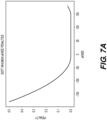
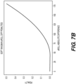
- the worn classification unit 552 receives the current knee angle and roll angle of both sensors. Using these angles a “penalty” is calculated which is a measure of how inhuman the angles are. This penalty is calculated as follows:
- a feasible human knee angle is anywhere between approximately 10 degrees and approximately 150 degrees so if the angle is within this range, the penalty is zero, but if it is outside this range there is a penalty.
- the parameters chosen for the above calculations can affect the sensitivity of the system to inhuman orientations.
- the present applicant has found that the more sensitive the system is set, the greater the risk of misclassification of worn/unworn state.
- the above parameters are shown by way of example only as ones that the applicant has determined to be advantageous following significant experimentation. Generally speaking, the parameters may be chosen such that false readings do not occur but unworn states are not missed.
- Figs. 7a & 7b show a graph of knee angle and roll angle penalties respectively as a function of the input angles.
- the final penalty is calculated as a sum of these two penalties, but a different mathematical combination of the knee and roll angle penalties could be used.
- the final penalty is then processed into a moving average (e.g. as an exponential recursive filter with forget rate of 0.05), which smooths the value of the final penalty over time. If this moving average goes over a threshold of 0.005, this indicates an unworn state.
- a moving average e.g. as an exponential recursive filter with forget rate of 0.05
- the sensor units Upon detection of an unworn state as described above, the sensor units, for example the metrics algorithm unit 548, can switch to a not worn state in terms of how they function. As discussed above, this is because in this situation, any data collected by the IMUs 416 will be "rogue" data, which is not indicative of the patient moving their knee.
- One option is to stop the accelerometers 418 and the gyroscopes 420 from collecting data.
- Another option is for the data not to be passed to the data conversion units 532, but to instead be discarded.
- the data could not be transmitted from the orientation data packing units 538 or it could be transmitted but discarded upon receipt by the orientation data unpacking units 544, 546.
- knee angle is not calculated by the knee angle estimation unit 550 or that the knee angles are calculated at subsequent times but either the worn classification unit 552 does not pass on the data or the data is passed on but not included by the ADL unit 556 in its correlation process.
- the worn classification unit 552 could indicate the not worn state to the ADL 556 in various ways that will occur to the skilled reader.
- One advantage of the present system and method is that the unworn state is detected without human intervention. Therefore, it is not reliant on a person having to remember to take any action to put the sensors into the unworn state.
- the ADL 556 could log a time duration for which the sensor system 400 is in the unworn state. This could be determined from the absence of data received or, if the data continues to be received, until the worn classification unit 552 indicates that the sensor(s) is no longer in an unworn state.
- setting the sensors 10 to charge on the charger 426 can trigger an unworn state and thus similar principles could be used to measure duration of time for which the sensors are charged. If the calculated penalty falls back to below the threshold, the sensor system 400 can return to normal operation.
- the sensor system 400 is set to await a user input before recommencing normal operation e.g.
- the system 400 will only recommence normal operation when the sensors 10 have been placed in position across the joint.
- an automatic return to normal operation could be implemented when the calculated penalty falls back to below the threshold, but it will be appreciated that it is possible for the two sensors 10a, 10b to be disposed relative to each other as they would be when fitted across a joint, even when not actually fitted to a joint. Thus in order to prevent normal operation recommencing in this situation, some further information would need to be gathered e.g. detection of skin contact.
- Fig. 8 shows a flowchart of a method in accordance with implementations of the invention.
- measurements are obtained from a pair of sensors mounted across a joint.
- these could be the sensors 10 mounted on a thigh and calf across a knee joint of a patient.
- the obtained measurements are used to calculate a relative angle between the sensors. In examples discussed above, this is performed by the worn classification functional unit 552. This could be an absolute difference in angle about any of the roll, pitch or yaw axes. In examples described above, the angle is roll. This calculation is simplified by the sensors 10 having both been placed on a same side of the leg 11 such that both lie substantially in the plane of the knee angle.
- the obtained measurements are used to calculate a joint angle. In examples discussed above, this is performed by the knee angle estimation functional unit 550. In examples described above, the measurements may have been used to calculate roll and pitch angles and these values can be used to calculate the knee angle. Thus the obtained measurements are used indirectly to calculate the knee angle.
- the relative angle and knee angle calculated are used to determine whether either of the sensors is unworn. In the examples discussed above, this determination could be made in the worn classification functional unit 552, which has determined roll angle at 812 and which can receive knee angle from the knee angle estimation functional unit 550. It could alternatively be made in the ADL unit 556 or by a separate functional unit.
- the functional units could be arranged differently and the calculations performed in a different order or by means of variations in the exemplary methods described above.
- the sensor components described above with reference to Fig. 4 could be different types or be used in different combinations and some of the described components may be provided as a single component. Whilst many examples above use relative roll angle between the two sensors 10, this is not essential and relative pitch or relative yaw could instead be used. Also, as mentioned above, in some implementations, mounting of the sensors on the wrong limbs can trigger an unworn state of the system, because doing this would result in a knee angle indicating that the knee is bending the wrong way.
- a different state could be triggered, the actual mounting position determined and taken into account during processing of the data in otherwise normal operation.
- the unworn detection system could be disabled prior to normal operation of the sensors, and a different procedure used to determine that the sensors are on the wrong limbs, to thereby trigger the different state. The unworn detection system could then be enabled so that subsequent removal etc. of the sensors would be detected.
- more than two sensors could be used.
- two sensors could be placed on one of the user's limbs. Measurements from such a third sensor could be processed in a similar manner to the processing described above for two sensors.
- One possibility is to process the data from the two sensors placed on one limb to obtain a set of data for that limb, and then process that in conjunction with the data from the other limb as described above.
- microcontroller 424 can be realized in digital electronic circuitry, integrated circuitry, specially designed application specific integrated circuits (ASICs), field programmable gate arrays (FPGAs) computer hardware, firmware, software, and/or combinations thereof.
- ASICs application specific integrated circuits
- FPGAs field programmable gate arrays
- These various aspects or features can include implementation in one or more computer programs that are executable and/or interpretable on a programmable system including at least one programmable processor such as the microcontroller 424, which can be special or general purpose, coupled to receive data and instructions from, and to transmit data and instructions to storage devices such as sticks.
- Such computer programs which can be software, software applications, applications, components, or code, include machine instructions for a programmable processor such as the microcontroller 424, and can be implemented in a high-level procedural and/or object-oriented programming language, and/or in assembly/machine language.
- machine-readable medium refers to any computer program product, apparatus and/or device, such as for example magnetic discs, optical disks, memory, and Programmable Logic Devices (PLDs), used to provide machine instructions and/or data to a programmable processor and which can receive instructions as a machine-readable signal.
- PLDs Programmable Logic Devices
- Such a machine-readable medium can store instructions transitorily or non-transitorily.
Landscapes
- Health & Medical Sciences (AREA)
- Life Sciences & Earth Sciences (AREA)
- Engineering & Computer Science (AREA)
- Physics & Mathematics (AREA)
- Surgery (AREA)
- Animal Behavior & Ethology (AREA)
- Veterinary Medicine (AREA)
- Biophysics (AREA)
- Pathology (AREA)
- Public Health (AREA)
- Biomedical Technology (AREA)
- Heart & Thoracic Surgery (AREA)
- Medical Informatics (AREA)
- Molecular Biology (AREA)
- General Health & Medical Sciences (AREA)
- Dentistry (AREA)
- Oral & Maxillofacial Surgery (AREA)
- Physiology (AREA)
- Artificial Intelligence (AREA)
- Computer Vision & Pattern Recognition (AREA)
- Psychiatry (AREA)
- Signal Processing (AREA)
- Geometry (AREA)
- Orthopedic Medicine & Surgery (AREA)
- Rheumatology (AREA)
- Measurement Of The Respiration, Hearing Ability, Form, And Blood Characteristics Of Living Organisms (AREA)
- Measurement Of Length, Angles, Or The Like Using Electric Or Magnetic Means (AREA)
- Treatment Of Fiber Materials (AREA)
Claims (15)
- Verfahren zum Bestimmen eines ungetragenen Zustands eines Sensorsystems (400), das ein Paar von Sensoren (10a, 10b) umfasst, die konfiguriert sind, um an einem ersten (12) und einem zweiten (13) Körperteil auf beiden Seiten eines Gelenks (4) angebracht zu werden, wobei jeder Sensor (10a; 10b) eine oder mehrere bewegungserfassende Vorrichtungen enthält, die es ermöglichen, entweder {i} das Nicken und/oder das Rollen des einzelnen Sensors (10a; 10b) zu bestimmen oder {ii} das relative Nicken und/oder Rollen zwischen den Sensoren (10a, 10b) zu bestimmen, wobei das Verfahren umfasst:Erlangen (810) einer oder mehrerer Messungen von jedem Sensor (10a; 10b);Berechnen (820) eines relativen Winkels zwischen den beiden Sensoren (10a, 10b) unter Verwendung einer oder mehrerer der erlangten einen oder mehreren Messungen;Berechnen (830), unter Verwendung einer oder mehrerer der erlangten einen oder mehreren Messungen, eines Gelenkwinkels zwischen dem ersten und dem zweiten Körperteil, wobei der Gelenkwinkel in einer Ebene normaler Beugung des Gelenks definiert ist; undBestimmen (840), basierend auf den berechneten Winkeln, ob einer oder beide Sensoren (10a; 10b) nicht angebracht sind, und wenn das der Fall ist, Bestimmen, dass sich das System in einem ungetragenen Zustand befindet.
- Verfahren nach Anspruch 1, wobei das Erlangen (810) einer oder mehrerer Messungen von jedem Sensor (10a, 10b) mehrere Male in einem Zeitraum durchgeführt wird und das Berechnen (820) eines relativen Winkels und das Berechnen (830) eines Gelenkwinkels unter Verwendung von Messungen durchgeführt werden, die zumindest bei einigen der mehreren Male erhalten wurden, wobei das Verfahren nach einem Bestimmen (840), dass sich das Sensorsystem in einem ungetragenen Zustand befindet, den weiteren Schritt umfasst: Anwenden eines anderen Verfahrens in Bezug auf das Berechnen des Gelenkwinkels zu nachfolgenden Zeitpunkten, wobei optional das Anwenden eines anderen Verfahrens eines oder mehrere der folgenden umfasst: kein Berechnen des Gelenkwinkels zu nachfolgenden Zeitpunkten; unterschiedliches Verarbeiten der berechneten Gelenkwinkel zu nachfolgenden Zeitpunkten im Vergleich zu jenen, die zu Zeitpunkten vor der Bestimmung berechnet wurden; kein Speichern der zu nachfolgenden Zeitpunkten berechneten Gelenkwinkel.
- Verfahren nach Anspruch 2, das ferner ein Korrelieren der zu mehreren Zeitpunkten berechneten Gelenkwinkel und relativen Winkel umfasst, um Informationen über das Gelenk (4) über den Zeitraum bereitzustellen, und wobei das Anwenden eines anderen Verfahrens das Weglassen jeglicher Daten umfasst, die unter Verwendung von zu späteren Zeitpunkten durchgeführten Messungen aus den Informationen berechnet wurden, wobei, optional, die Informationen eines oder mehrere der folgenden umfassen: Variation des Gelenkwinkels während des Zeitraums; Dauer der Zeit, in der das Gelenk (4) aktiv ist; Dauer der Zeit, in der das Gelenk eine Last trägt; Länge des Zeitraums; und, wenn das Gelenk (4) ein Knie ist, Schrittzahl über den Zeitraum.
- Verfahren nach Anspruch 3, wobei das Anwenden eines anderen Verfahrens ein Durchführen von Berechnungen umfasst, um aus den Informationen über das Gelenk (4) andere Informationen bereitzustellen, wobei die anderen Informationen eine oder mehrere der folgenden umfassen: die Zeit des Nichttragens; und, wenn der erste Sensor (10a) als aufladend bestimmt wird, die Aufladezeit.
- Verfahren nach einem der vorhergehenden Ansprüche, wobei ein ungetragener Zustand eines oder mehrere der folgenden aufweist: der erste Sensor wurde zumindest teilweise aus seiner angebrachten Position entfernt; der erste Sensor fällt zumindest teilweise aus seiner angebrachten Position; der erste Sensor ist eingeschaltet, aber nicht am ersten Körperteil angebracht; der zweite Sensor ist eingeschaltet, aber nicht am zweiten Körperteil angebracht.
- Verfahren nach einem der vorhergehenden Ansprüche, wobei das Bestimmen, ob einer oder beide Sensoren nicht angebracht sind, ein Bestimmen umfasst, ob der erste Sensor (10a) an dem ersten Körperteil (12) angebracht ist, was ein Berechnen eines Wertes einer Funktion der berechneten Winkel umfasst.
- Verfahren nach Anspruch 6, das ferner ein Verarbeiten mehrerer berechneter Werte der Funktion über einen Zeitraum umfasst, um einen gleitenden Mittelwert für die Funktion zu bestimmen, wobei das Bestimmen ferner ein Vergleichen des bestimmten gleitenden Mittelwerts mit einem Schwellenwert umfasst.
- Verfahren nach Anspruch 6 oder Anspruch 7, wobei die Funktion eine Funktion einer gemeinsamen Winkelstrafe und einer relativen Winkelstrafe umfasst, wobei optional:(i) wenn der Gelenkwinkel innerhalb eines durchführbaren Bereichs für das Gelenk (4) liegt, die Gelenkwinkelstrafe Null beträgt, und wenn der Gelenkwinkel nicht innerhalb eines durchführbaren Bereichs für das Gelenk (4) liegt, die Gelenkwinkelstrafe einen Wert aufweist, der davon abhängt, wie weit außerhalb des durchführbaren Bereichs der Gelenkwinkel liegt; und/oder(ii) wenn der relative Winkel kleiner oder gleich einem relativen Schwellenwert ist, die relative Winkelstrafe Null beträgt, und wenn die relative Winkelstrafe größer als der relative Schwellenwert ist, die relative Winkelstrafe davon abhängt, wie viel größer der relative Winkel als der relative Schwellenwert ist.
- Verfahren nach einem der vorhergehenden Ansprüche, wobei der relative Winkel eine Differenz im Neigungswinkel der beiden Körperteile ist, wobei das Neigen um eine Achse erfolgt, die senkrecht oder im Wesentlichen senkrecht auf der Ebene steht, in der der Gelenkwinkel definiert ist, wobei, optional, der Gelenkwinkel in einer x-z-Ebene definiert ist und der Neigungswinkel in einer x-y-Ebene definiert ist und nicht Null beträgt, wenn der erste und der zweite Körperteil ein relatives Rollen um die x-Achse erfahren.
- Verfahren nach einem der vorhergehenden Ansprüche, das ferner vor dem Erlangen (810) umfasst:(i) Bestimmen, ob der erste und der zweite Sensor an korrekten jeweiligen ersten und zweiten Körperteilen (12; 14) und/oder in im Wesentlichen einer vorbestimmten Ausrichtung relativ zu den korrekten jeweiligen ersten und zweiten Körperteilen (12; 14) angebracht sind, und wenn festgestellt wird, dass einer oder beide Sensoren (10a; 10b) an dem falschen Körperteil oder in einer anderen Ausrichtung als der vorbestimmten Ausrichtung angebracht sind, Anpassen der Berechnungsschritte, um eine tatsächliche bestimmte Anbringungsstelle und/oder Ausrichtung zu berücksichtigen; und/oder(ii) Kalibrieren des ersten und des zweiten Sensors in Bezug auf eine vorbestimmte Ausrichtung relativ zu dem jeweiligen ersten und zweiten Körperteil (12; 14).
- Verfahren nach einem der vorhergehenden Ansprüche, wobei das Gelenk (4) ein Knie oder ein Ellbogen ist.
- System (400) zur Bereitstellung von Informationen über ein Gelenk (4), das umfasst:eine erste Sensoreinheit (10a), die konfiguriert ist, um an einem ersten Körperteil (12) auf einer ersten Seite eines Gelenks (4) angebracht zu werden, wobei die erste Sensoreinheit (10a) umfasst:einen oder mehrere erste Sensoren (10a), der oder die eingerichtet ist oder sind, um eine oder mehrere Messungen in Bezug auf den ersten Körperteil (12) und eine oder mehrere Messungen in Bezug auf den ersten Sensor (10a) vorzunehmen; undeinen Sender, der eingerichtet ist, um die vorgenommenen Messungen zu übertragen; undeine zweite, übergeordnete Sensoreinheit (10b), die konfiguriert ist, um an einem zweiten Körperteil (12) auf einer zweiten Seite eines Gelenks (4) angebracht zu werden, wobei die zweite übergeordnete Sensoreinheit (10b) umfasst:einen oder mehrere zweite Sensoren (10b), der oder die eingerichtet ist oder sind, um eine oder mehrere Messungen in Bezug auf den zweiten Körperteil (14) und eine oder mehrere Messungen in Bezug auf den zweiten Sensor (10b) vorzunehmen;einen Empfänger, der eingerichtet ist, um die von dem Sender der ersten Sensoreinheit gesendeten Messwerte zu empfangen; undeine Berechnungseinheit, die konfiguriert ist, um unter Verwendung einer oder mehrerer der Messungen einen relativen Winkel zwischen den beiden Sensoren (10a, 10b) und einen Gelenkwinkel zwischen dem ersten und dem zweiten Körperteil (12, 14) zu berechnen, wobei der Gelenkwinkel in einer Ebene normaler Beugung des Gelenks (4) definiert ist, wobei die Berechnungseinheit ferner konfiguriert ist, um auf der Grundlage der berechneten Winkel zu bestimmen, ob einer oder beide der Sensoreinheiten (10a, 10b) nicht angebracht ist oder sind, und wenn dies der Fall ist, zu bestimmen, dass sich das System (400) in einem ungetragenen Zustand befindet,wobei jeder des einen oder der mehreren ersten Sensoren (10a; 10b) eine oder mehrere Bewegungserfassungsvorrichtungen enthält, die es erlaubt oder erlauben, entweder {i} das Nicken und/oder Rollen des einzelnen ersten Sensors (10a; 10b) zu bestimmen oder {ii} das relative Nicken und/oder Rollen zwischen dem ersten Sensor und einem zweiten Sensor (10a, 10b) zu bestimmen, und wobei jeder des einen oder der mehreren zweiten Sensoren (10a; 10b) eine oder mehrere bewegungserfassende Vorrichtungen enthält, die es erlaubt oder erlauben, entweder {i} das Nicken und/oder Rollen des einzelnen zweiten Sensors (10a; 10b) zu bestimmen oder {ii} das relative Nicken und/oder Rollen zwischen dem zweiten Sensor und einem ersten Sensor (10a, 10b) zu bestimmen.
- System nach Anspruch 12, wobei die erste und die zweite Sensoreinheit (10a, 10b) konfiguriert sind, um in einem Zeitraum Messungen mehrere Male vorzunehmen, und die Berechnungseinheit konfiguriert ist, um einen relativen Winkel und einen Gelenkwinkel unter Verwendung von Messungen zu berechnen, die zu jedem von zumindest einigen der mehreren Male erhalten werden, wobei die Berechnungseinheit ferner konfiguriert ist, um nach einer Bestimmung, dass sich das System (400) in einem ungetragenen Zustand befindet, ein anderes Verfahren in Bezug auf die Berechnung des Gelenkwinkels zu nachfolgenden Zeitpunkten anzuwenden.
- System nach Anspruch 13, wobei die Berechnungseinheit ferner konfiguriert ist, um die Gelenkwinkel und die relativen Winkel, die zu den mehreren Malen berechnet wurden, zu korrelieren, um Informationen über das Gelenk (4) über den Zeitraum bereitzustellen, und wobei das Anwenden eines anderen Verfahrens das Weglassen jeglicher Daten, die sich auf Messungen beziehen, die zu späteren Zeitpunkten vorgenommen wurden, aus den Informationen umfasst, wobei, optional:(i) die zweite übergeordnete Sensoreinheit konfiguriert ist, um die Informationen an eine mobile Vorrichtung zur Anzeige durch einen Benutzer bereitzustellen; und/oder(ii) die Informationen der Beurteilung der Gesundheit und/oder der Rehabilitation des Gelenks (4) dienen.
- System nach einem der Ansprüche 12 bis 14, wobei die erste und die zweite Sensoreinheit (10a, 10b) im Allgemeinen planar sind und eine Vorder- und eine Rückseite aufweisen und so konfiguriert sind, dass ihre Rückseiten auf dem ersten und dem zweiten Körperteil (12, 14) an einer Seite des Gelenks im Wesentlichen parallel zur Ebene der normalen Beugung des Gelenks (4) angebracht werden.
Priority Applications (1)
| Application Number | Priority Date | Filing Date | Title |
|---|---|---|---|
| EP24173748.5A EP4385406A3 (de) | 2019-10-18 | 2020-10-15 | Sensorbestimmung |
Applications Claiming Priority (2)
| Application Number | Priority Date | Filing Date | Title |
|---|---|---|---|
| GB1915139.8A GB2588238B (en) | 2019-10-18 | 2019-10-18 | Sensor determination |
| PCT/IB2020/059717 WO2021074852A1 (en) | 2019-10-18 | 2020-10-15 | Sensor determination |
Related Child Applications (1)
| Application Number | Title | Priority Date | Filing Date |
|---|---|---|---|
| EP24173748.5A Division EP4385406A3 (de) | 2019-10-18 | 2020-10-15 | Sensorbestimmung |
Publications (2)
| Publication Number | Publication Date |
|---|---|
| EP4044904A1 EP4044904A1 (de) | 2022-08-24 |
| EP4044904B1 true EP4044904B1 (de) | 2024-05-29 |
Family
ID=68728183
Family Applications (2)
| Application Number | Title | Priority Date | Filing Date |
|---|---|---|---|
| EP20797863.6A Active EP4044904B1 (de) | 2019-10-18 | 2020-10-15 | Sensorbestimmung |
| EP24173748.5A Pending EP4385406A3 (de) | 2019-10-18 | 2020-10-15 | Sensorbestimmung |
Family Applications After (1)
| Application Number | Title | Priority Date | Filing Date |
|---|---|---|---|
| EP24173748.5A Pending EP4385406A3 (de) | 2019-10-18 | 2020-10-15 | Sensorbestimmung |
Country Status (8)
| Country | Link |
|---|---|
| US (1) | US20220361770A1 (de) |
| EP (2) | EP4044904B1 (de) |
| JP (1) | JP7726875B2 (de) |
| KR (1) | KR102959488B1 (de) |
| CN (1) | CN115209788B (de) |
| AU (1) | AU2020366718A1 (de) |
| GB (1) | GB2588238B (de) |
| WO (1) | WO2021074852A1 (de) |
Families Citing this family (9)
| Publication number | Priority date | Publication date | Assignee | Title |
|---|---|---|---|---|
| WO2018081795A1 (en) | 2016-10-31 | 2018-05-03 | Zipline Medical, Inc. | Systems and methods for monitoring physical therapy of the knee and other joints |
| GB2574074B (en) | 2018-07-27 | 2020-05-20 | Mclaren Applied Tech Ltd | Time synchronisation |
| GB2588236B (en) | 2019-10-18 | 2024-03-20 | Mclaren Applied Ltd | Gyroscope bias estimation |
| USD1110333S1 (en) | 2021-11-05 | 2026-01-27 | Howmedica Osteonics Corp. | Display screen or portion thereof with animated graphical user interface |
| USD1053901S1 (en) | 2021-11-05 | 2024-12-10 | Howmedica Osteonics Corp. | Display screen or portion thereof with graphical user interface |
| USD1120934S1 (en) | 2021-11-05 | 2026-03-31 | Howmedica Osteonics Corp. | Display screen or portion thereof with graphical user interface |
| USD1067239S1 (en) | 2021-11-05 | 2025-03-18 | Howmedica Osteonics Corp. | Display screen or portion thereof with animated graphical user interface |
| USD1084008S1 (en) | 2021-11-05 | 2025-07-15 | Howmedica Osteonics Corp. | Display screen or portion thereof with graphical user interface |
| JP7529338B1 (ja) * | 2024-01-18 | 2024-08-06 | 株式会社sci-bone | 情報処理装置、情報処理方法及び情報処理システム |
Family Cites Families (41)
| Publication number | Priority date | Publication date | Assignee | Title |
|---|---|---|---|---|
| US6890312B1 (en) * | 2001-12-03 | 2005-05-10 | William B. Priester | Joint angle indication system |
| US7033281B2 (en) * | 2002-03-22 | 2006-04-25 | Carnahan James V | Augmented kinematic feedback device and method |
| KR20070095407A (ko) * | 2005-01-26 | 2007-09-28 | 벤틀리 키네틱스 인코포레이티드 | 운동동작의 분석 및 지도를 위한 방법 및 시스템 |
| US7862524B2 (en) * | 2006-03-23 | 2011-01-04 | Carignan Craig R | Portable arm exoskeleton for shoulder rehabilitation |
| WO2009014644A1 (en) * | 2007-07-20 | 2009-01-29 | Ossur Hf | Prosthetic or orthopedic device having feedback |
| EP2057944A1 (de) * | 2007-11-07 | 2009-05-13 | Nederlandse Organisatie voor toegepast-natuurwetenschappelijk Onderzoek TNO | Messung des Winkels zwischen einem ersten und einem zweiten Element unter dynamischen Bedingungen |
| US8322238B2 (en) * | 2008-05-06 | 2012-12-04 | Abbott Laboratories | System, apparatus, and methods for evaluating medical device performance |
| DE102008030534A1 (de) * | 2008-06-27 | 2009-12-31 | Bort Medical Gmbh | Vorrichtung zum Bestimmen der Stabilität eines Kniegelenks |
| US8421854B2 (en) * | 2008-07-24 | 2013-04-16 | Noah Zerkin | System and method for motion capture |
| US8444564B2 (en) * | 2009-02-02 | 2013-05-21 | Jointvue, Llc | Noninvasive diagnostic system |
| US9656117B2 (en) * | 2009-06-19 | 2017-05-23 | Tau Orthopedics, Llc | Wearable resistance garment with power measurement |
| EP2353505A1 (de) * | 2010-02-03 | 2011-08-10 | Nederlandse Organisatie voor toegepast -natuurwetenschappelijk onderzoek TNO | Verfahren, Klammer und System zum Messen der Biegung oder Kurvung eines menschlichen oder tierischen Körpers |
| CA2789584A1 (en) * | 2010-02-12 | 2011-08-18 | Freedom Innovations, L.L.C. | Novel enhanced methods for mimicking human gait with prosthetic knee devices |
| US9011293B2 (en) * | 2011-01-26 | 2015-04-21 | Flow-Motion Research And Development Ltd. | Method and system for monitoring and feed-backing on execution of physical exercise routines |
| US9517339B2 (en) * | 2013-02-20 | 2016-12-13 | Indiana University Research And Technology Corporation | Method and system for training an individual |
| US20140257142A1 (en) * | 2013-03-08 | 2014-09-11 | Thompson Sarkodie-Gyan | Sensor for reliable measurement of joint angles |
| US20150022362A1 (en) * | 2013-07-22 | 2015-01-22 | Smart Sport Systems, LLC | Wearable device configured to detect improper movement of a knee and alert wearers to the improper movement |
| US9028407B1 (en) * | 2013-12-13 | 2015-05-12 | Safer Care LLC | Methods and apparatus for monitoring patient conditions |
| CN103750841B (zh) * | 2014-01-20 | 2015-06-24 | 上海交通大学 | 基于mems惯性传感器的人体膝关节角度无线检测系统及方法 |
| JP2014208257A (ja) * | 2014-06-11 | 2014-11-06 | 国立大学法人東北大学 | 歩行解析システム |
| KR102365191B1 (ko) * | 2014-10-20 | 2022-02-18 | 삼성전자주식회사 | 사용자의 동작을 인식하기 위한 장치 및 방법 |
| JP6730573B2 (ja) * | 2015-03-17 | 2020-07-29 | 国立大学法人秋田大学 | 重症度評価支援システム及びプログラム |
| US20160278647A1 (en) * | 2015-03-26 | 2016-09-29 | Intel Corporation | Misalignment detection of a wearable device |
| US10646157B2 (en) * | 2015-05-08 | 2020-05-12 | Sharp Laboratories Of America, Inc. | System and method for measuring body joint range of motion |
| US20160324447A1 (en) * | 2015-05-08 | 2016-11-10 | Sharp Laboratories of America (SLA), Inc. | System and Method for Determining Orientation of Body Segments Using Inertial Measurement Units |
| EP3376414B1 (de) * | 2015-11-13 | 2021-02-24 | Innomotion Incorporation (Shanghai) | System und verfahren für gelenkbewegungsdetektion und dynamisches beurteilungsverfahren und system für kniegelenk |
| US10463279B2 (en) * | 2016-02-19 | 2019-11-05 | Trustees Of Dartmouth College | Movement monitoring systems and methods |
| US10869618B2 (en) * | 2016-04-14 | 2020-12-22 | Thomas William Quintel | Diagnostic measurement devices and methods |
| JP6501727B2 (ja) * | 2016-06-02 | 2019-04-17 | 株式会社スペース・バイオ・ラボラトリーズ | 歩行動作補助装置 |
| EP3471611A1 (de) * | 2016-06-15 | 2019-04-24 | Leaf Healthcare, Inc. | Systeme, vorrichtungen und verfahren zur überwachung einer person mit einem wearable-sensor und verwaltung eines drehungsplans für die person |
| WO2018007600A1 (en) * | 2016-07-08 | 2018-01-11 | Hunter Douglas Industries B.V. | Method of manufacture of a linear panel |
| KR102254024B1 (ko) * | 2016-11-18 | 2021-05-18 | 재단법인대구경북과학기술원 | 경직 평가 장치, 방법 및 시스템 |
| KR102018795B1 (ko) * | 2017-02-08 | 2019-09-05 | 구글 엘엘씨 | 인간공학적 평가 의복 |
| US20190066832A1 (en) * | 2017-02-20 | 2019-02-28 | KangarooHealth, Inc. | Method for detecting patient risk and selectively notifying a care provider of at-risk patients |
| US11000229B2 (en) * | 2017-08-03 | 2021-05-11 | Orthini, LLC | Systems, methods, and apparatuses for integrating a body joint rehabilitation regimen with a wearable movement capture device operable in conjunction with a cloud based computing environment |
| KR101859549B1 (ko) * | 2017-11-15 | 2018-05-21 | (주)컬처릿 | 웨어러블 센서 기반의 동작 훈련 가이드 시스템 및 그 방법 |
| KR102074043B1 (ko) * | 2017-12-08 | 2020-03-02 | 한국로봇융합연구원 | 관절센서를 이용한 센서 오차 보정장치, 보정방법 |
| WO2019161232A1 (en) * | 2018-02-17 | 2019-08-22 | President And Fellows Of Harvard College | Wearable devices for protecting against musculoskeletal injuries and enhancing performance |
| US20190374161A1 (en) * | 2018-06-08 | 2019-12-12 | Seismic Holdings, Inc. | Exosuit systems and methods for detecting and analyzing lifting and bending |
| CN109528205B (zh) * | 2018-11-15 | 2021-06-15 | 歌尔科技有限公司 | 一种提示方法、装置、头戴设备及计算机可读存储介质 |
| CN109945889B (zh) * | 2019-04-17 | 2023-07-25 | 合肥工业大学 | 一种基于双姿态传感器的关节角度测量方法 |
-
2019
- 2019-10-18 GB GB1915139.8A patent/GB2588238B/en active Active
-
2020
- 2020-10-15 EP EP20797863.6A patent/EP4044904B1/de active Active
- 2020-10-15 WO PCT/IB2020/059717 patent/WO2021074852A1/en not_active Ceased
- 2020-10-15 US US17/754,966 patent/US20220361770A1/en active Pending
- 2020-10-15 KR KR1020227016385A patent/KR102959488B1/ko active Active
- 2020-10-15 AU AU2020366718A patent/AU2020366718A1/en active Pending
- 2020-10-15 EP EP24173748.5A patent/EP4385406A3/de active Pending
- 2020-10-15 CN CN202080084796.7A patent/CN115209788B/zh active Active
- 2020-10-15 JP JP2022523256A patent/JP7726875B2/ja active Active
Also Published As
| Publication number | Publication date |
|---|---|
| KR102959488B1 (ko) | 2026-04-30 |
| AU2020366718A1 (en) | 2022-06-02 |
| US20220361770A1 (en) | 2022-11-17 |
| KR20220143637A (ko) | 2022-10-25 |
| WO2021074852A1 (en) | 2021-04-22 |
| GB2588238A (en) | 2021-04-21 |
| EP4044904A1 (de) | 2022-08-24 |
| GB2588238B (en) | 2023-11-22 |
| JP2022552863A (ja) | 2022-12-20 |
| GB201915139D0 (en) | 2019-12-04 |
| CN115209788B (zh) | 2026-03-27 |
| EP4385406A3 (de) | 2024-08-21 |
| JP7726875B2 (ja) | 2025-08-20 |
| EP4385406A2 (de) | 2024-06-19 |
| CN115209788A (zh) | 2022-10-18 |
Similar Documents
| Publication | Publication Date | Title |
|---|---|---|
| EP4385406A2 (de) | Sensorbestimmung | |
| AU2021201226B2 (en) | Systems and methods for monitoring an orthopedic implant and rehabilitation | |
| US20210030357A1 (en) | System and methods for monitoring physical therapy and rehabilitation of joints | |
| AU2018216893B2 (en) | System and methods for monitoring physical therapy and rehabilitation of joints | |
| US10456075B2 (en) | Method for calibrating apparatus for monitoring rehabilitation from joint surgery | |
| US8109890B2 (en) | Body movement monitoring device | |
| US20170265800A1 (en) | Apparatus and Method for Monitoring Rehabilitation from Joint Surgery | |
| EP1938749A2 (de) | Vorrichtung zur Überwachung des Bewegungsbereichs eines Verbindungsstücks | |
| US20150032034A1 (en) | Apparatus and method for quantifying stability of the knee | |
| US20170238849A1 (en) | Movement monitoring systems and methods | |
| JP2020192307A (ja) | 下肢筋力評価方法、下肢筋力評価プログラム、下肢筋力評価装置及び下肢筋力評価システム | |
| EP2394573A1 (de) | Kniesehnentestvorrichtung zum Messen der Zug- und Drehschlaffheit | |
| WO2004084725A1 (en) | Motion analysis system and method | |
| WO2009020914A1 (en) | Angular displacement sensor for joints and associated system and methods | |
| Figueiredo et al. | Instrumented insole system for ambulatory and robotic walking assistance: First advances | |
| EP3847961B1 (de) | Programm zur bestimmung des gehzustands, verfahren zur bestimmung des gehzustands und vorrichtung zur informationsverarbeitung | |
| CN112006703B (zh) | 下肢肌肉力量评价方法、评价装置、评价系统以及记录介质 | |
| EP4179970A1 (de) | Sensorvorrichtung zur gangüberwachung | |
| Roetenberg et al. | Camera-marker and inertial sensor fusion for improved motion tracking | |
| Kellner et al. | Online monitoring of posture for preventive medicine using low-cost inertial sensors | |
| Evans et al. | Mobile gait analysis system for lower limb amputee high-level activity rehabilitation | |
| Aminian et al. | Body movement monitoring device |
Legal Events
| Date | Code | Title | Description |
|---|---|---|---|
| STAA | Information on the status of an ep patent application or granted ep patent |
Free format text: STATUS: UNKNOWN |
|
| STAA | Information on the status of an ep patent application or granted ep patent |
Free format text: STATUS: THE INTERNATIONAL PUBLICATION HAS BEEN MADE |
|
| PUAI | Public reference made under article 153(3) epc to a published international application that has entered the european phase |
Free format text: ORIGINAL CODE: 0009012 |
|
| STAA | Information on the status of an ep patent application or granted ep patent |
Free format text: STATUS: REQUEST FOR EXAMINATION WAS MADE |
|
| 17P | Request for examination filed |
Effective date: 20220513 |
|
| AK | Designated contracting states |
Kind code of ref document: A1 Designated state(s): AL AT BE BG CH CY CZ DE DK EE ES FI FR GB GR HR HU IE IS IT LI LT LU LV MC MK MT NL NO PL PT RO RS SE SI SK SM TR |
|
| RAP3 | Party data changed (applicant data changed or rights of an application transferred) |
Owner name: MCLAREN APPLIED LIMITED |
|
| DAV | Request for validation of the european patent (deleted) | ||
| DAX | Request for extension of the european patent (deleted) | ||
| STAA | Information on the status of an ep patent application or granted ep patent |
Free format text: STATUS: EXAMINATION IS IN PROGRESS |
|
| 17Q | First examination report despatched |
Effective date: 20230525 |
|
| GRAP | Despatch of communication of intention to grant a patent |
Free format text: ORIGINAL CODE: EPIDOSNIGR1 |
|
| STAA | Information on the status of an ep patent application or granted ep patent |
Free format text: STATUS: GRANT OF PATENT IS INTENDED |
|
| INTG | Intention to grant announced |
Effective date: 20231221 |
|
| GRAS | Grant fee paid |
Free format text: ORIGINAL CODE: EPIDOSNIGR3 |
|
| GRAA | (expected) grant |
Free format text: ORIGINAL CODE: 0009210 |
|
| STAA | Information on the status of an ep patent application or granted ep patent |
Free format text: STATUS: THE PATENT HAS BEEN GRANTED |
|
| AK | Designated contracting states |
Kind code of ref document: B1 Designated state(s): AL AT BE BG CH CY CZ DE DK EE ES FI FR GR HR HU IE IS IT LI LT LU LV MC MK MT NL NO PL PT RO RS SE SI SK SM TR |
|
| P01 | Opt-out of the competence of the unified patent court (upc) registered |
Effective date: 20240419 |
|
| RBV | Designated contracting states (corrected) |
Designated state(s): AL AT BE BG CH CY CZ DE DK EE ES FI FR GR HR HU IE IS IT LI LT LU LV MC MK MT NL NO PL PT RO RS SE SI SK SM TR |
|
| REG | Reference to a national code |
Ref country code: CH Ref legal event code: EP |
|
| REG | Reference to a national code |
Ref country code: IE Ref legal event code: FG4D |
|
| REG | Reference to a national code |
Ref country code: DE Ref legal event code: R096 Ref document number: 602020031733 Country of ref document: DE |
|
| REG | Reference to a national code |
Ref country code: LT Ref legal event code: MG9D |
|
| REG | Reference to a national code |
Ref country code: NL Ref legal event code: MP Effective date: 20240529 |
|
| PG25 | Lapsed in a contracting state [announced via postgrant information from national office to epo] |
Ref country code: IS Free format text: LAPSE BECAUSE OF FAILURE TO SUBMIT A TRANSLATION OF THE DESCRIPTION OR TO PAY THE FEE WITHIN THE PRESCRIBED TIME-LIMIT Effective date: 20240929 |
|
| PG25 | Lapsed in a contracting state [announced via postgrant information from national office to epo] |
Ref country code: BG Free format text: LAPSE BECAUSE OF FAILURE TO SUBMIT A TRANSLATION OF THE DESCRIPTION OR TO PAY THE FEE WITHIN THE PRESCRIBED TIME-LIMIT Effective date: 20240529 |
|
| PG25 | Lapsed in a contracting state [announced via postgrant information from national office to epo] |
Ref country code: HR Free format text: LAPSE BECAUSE OF FAILURE TO SUBMIT A TRANSLATION OF THE DESCRIPTION OR TO PAY THE FEE WITHIN THE PRESCRIBED TIME-LIMIT Effective date: 20240529 Ref country code: FI Free format text: LAPSE BECAUSE OF FAILURE TO SUBMIT A TRANSLATION OF THE DESCRIPTION OR TO PAY THE FEE WITHIN THE PRESCRIBED TIME-LIMIT Effective date: 20240529 |
|
| PG25 | Lapsed in a contracting state [announced via postgrant information from national office to epo] |
Ref country code: GR Free format text: LAPSE BECAUSE OF FAILURE TO SUBMIT A TRANSLATION OF THE DESCRIPTION OR TO PAY THE FEE WITHIN THE PRESCRIBED TIME-LIMIT Effective date: 20240830 |
|
| REG | Reference to a national code |
Ref country code: AT Ref legal event code: MK05 Ref document number: 1689927 Country of ref document: AT Kind code of ref document: T Effective date: 20240529 |
|
| PG25 | Lapsed in a contracting state [announced via postgrant information from national office to epo] |
Ref country code: ES Free format text: LAPSE BECAUSE OF FAILURE TO SUBMIT A TRANSLATION OF THE DESCRIPTION OR TO PAY THE FEE WITHIN THE PRESCRIBED TIME-LIMIT Effective date: 20240529 |
|
| PG25 | Lapsed in a contracting state [announced via postgrant information from national office to epo] |
Ref country code: AT Free format text: LAPSE BECAUSE OF FAILURE TO SUBMIT A TRANSLATION OF THE DESCRIPTION OR TO PAY THE FEE WITHIN THE PRESCRIBED TIME-LIMIT Effective date: 20240529 |
|
| PG25 | Lapsed in a contracting state [announced via postgrant information from national office to epo] |
Ref country code: PL Free format text: LAPSE BECAUSE OF FAILURE TO SUBMIT A TRANSLATION OF THE DESCRIPTION OR TO PAY THE FEE WITHIN THE PRESCRIBED TIME-LIMIT Effective date: 20240529 |
|
| PG25 | Lapsed in a contracting state [announced via postgrant information from national office to epo] |
Ref country code: LV Free format text: LAPSE BECAUSE OF FAILURE TO SUBMIT A TRANSLATION OF THE DESCRIPTION OR TO PAY THE FEE WITHIN THE PRESCRIBED TIME-LIMIT Effective date: 20240529 |
|
| PG25 | Lapsed in a contracting state [announced via postgrant information from national office to epo] |
Ref country code: PL Free format text: LAPSE BECAUSE OF FAILURE TO SUBMIT A TRANSLATION OF THE DESCRIPTION OR TO PAY THE FEE WITHIN THE PRESCRIBED TIME-LIMIT Effective date: 20240529 Ref country code: NO Free format text: LAPSE BECAUSE OF FAILURE TO SUBMIT A TRANSLATION OF THE DESCRIPTION OR TO PAY THE FEE WITHIN THE PRESCRIBED TIME-LIMIT Effective date: 20240829 Ref country code: LV Free format text: LAPSE BECAUSE OF FAILURE TO SUBMIT A TRANSLATION OF THE DESCRIPTION OR TO PAY THE FEE WITHIN THE PRESCRIBED TIME-LIMIT Effective date: 20240529 Ref country code: IS Free format text: LAPSE BECAUSE OF FAILURE TO SUBMIT A TRANSLATION OF THE DESCRIPTION OR TO PAY THE FEE WITHIN THE PRESCRIBED TIME-LIMIT Effective date: 20240929 Ref country code: HR Free format text: LAPSE BECAUSE OF FAILURE TO SUBMIT A TRANSLATION OF THE DESCRIPTION OR TO PAY THE FEE WITHIN THE PRESCRIBED TIME-LIMIT Effective date: 20240529 Ref country code: GR Free format text: LAPSE BECAUSE OF FAILURE TO SUBMIT A TRANSLATION OF THE DESCRIPTION OR TO PAY THE FEE WITHIN THE PRESCRIBED TIME-LIMIT Effective date: 20240830 Ref country code: FI Free format text: LAPSE BECAUSE OF FAILURE TO SUBMIT A TRANSLATION OF THE DESCRIPTION OR TO PAY THE FEE WITHIN THE PRESCRIBED TIME-LIMIT Effective date: 20240529 Ref country code: ES Free format text: LAPSE BECAUSE OF FAILURE TO SUBMIT A TRANSLATION OF THE DESCRIPTION OR TO PAY THE FEE WITHIN THE PRESCRIBED TIME-LIMIT Effective date: 20240529 Ref country code: BG Free format text: LAPSE BECAUSE OF FAILURE TO SUBMIT A TRANSLATION OF THE DESCRIPTION OR TO PAY THE FEE WITHIN THE PRESCRIBED TIME-LIMIT Effective date: 20240529 Ref country code: AT Free format text: LAPSE BECAUSE OF FAILURE TO SUBMIT A TRANSLATION OF THE DESCRIPTION OR TO PAY THE FEE WITHIN THE PRESCRIBED TIME-LIMIT Effective date: 20240529 Ref country code: RS Free format text: LAPSE BECAUSE OF FAILURE TO SUBMIT A TRANSLATION OF THE DESCRIPTION OR TO PAY THE FEE WITHIN THE PRESCRIBED TIME-LIMIT Effective date: 20240829 |
|
| PG25 | Lapsed in a contracting state [announced via postgrant information from national office to epo] |
Ref country code: NL Free format text: LAPSE BECAUSE OF FAILURE TO SUBMIT A TRANSLATION OF THE DESCRIPTION OR TO PAY THE FEE WITHIN THE PRESCRIBED TIME-LIMIT Effective date: 20240529 |
|
| PG25 | Lapsed in a contracting state [announced via postgrant information from national office to epo] |
Ref country code: NL Free format text: LAPSE BECAUSE OF FAILURE TO SUBMIT A TRANSLATION OF THE DESCRIPTION OR TO PAY THE FEE WITHIN THE PRESCRIBED TIME-LIMIT Effective date: 20240529 |
|
| PG25 | Lapsed in a contracting state [announced via postgrant information from national office to epo] |
Ref country code: DK Free format text: LAPSE BECAUSE OF FAILURE TO SUBMIT A TRANSLATION OF THE DESCRIPTION OR TO PAY THE FEE WITHIN THE PRESCRIBED TIME-LIMIT Effective date: 20240529 |
|
| PG25 | Lapsed in a contracting state [announced via postgrant information from national office to epo] |
Ref country code: EE Free format text: LAPSE BECAUSE OF FAILURE TO SUBMIT A TRANSLATION OF THE DESCRIPTION OR TO PAY THE FEE WITHIN THE PRESCRIBED TIME-LIMIT Effective date: 20240529 |
|
| PG25 | Lapsed in a contracting state [announced via postgrant information from national office to epo] |
Ref country code: CZ Free format text: LAPSE BECAUSE OF FAILURE TO SUBMIT A TRANSLATION OF THE DESCRIPTION OR TO PAY THE FEE WITHIN THE PRESCRIBED TIME-LIMIT Effective date: 20240529 |
|
| PG25 | Lapsed in a contracting state [announced via postgrant information from national office to epo] |
Ref country code: RO Free format text: LAPSE BECAUSE OF FAILURE TO SUBMIT A TRANSLATION OF THE DESCRIPTION OR TO PAY THE FEE WITHIN THE PRESCRIBED TIME-LIMIT Effective date: 20240529 Ref country code: SK Free format text: LAPSE BECAUSE OF FAILURE TO SUBMIT A TRANSLATION OF THE DESCRIPTION OR TO PAY THE FEE WITHIN THE PRESCRIBED TIME-LIMIT Effective date: 20240529 |
|
| PG25 | Lapsed in a contracting state [announced via postgrant information from national office to epo] |
Ref country code: SM Free format text: LAPSE BECAUSE OF FAILURE TO SUBMIT A TRANSLATION OF THE DESCRIPTION OR TO PAY THE FEE WITHIN THE PRESCRIBED TIME-LIMIT Effective date: 20240529 |
|
| PG25 | Lapsed in a contracting state [announced via postgrant information from national office to epo] |
Ref country code: SM Free format text: LAPSE BECAUSE OF FAILURE TO SUBMIT A TRANSLATION OF THE DESCRIPTION OR TO PAY THE FEE WITHIN THE PRESCRIBED TIME-LIMIT Effective date: 20240529 Ref country code: SK Free format text: LAPSE BECAUSE OF FAILURE TO SUBMIT A TRANSLATION OF THE DESCRIPTION OR TO PAY THE FEE WITHIN THE PRESCRIBED TIME-LIMIT Effective date: 20240529 Ref country code: RO Free format text: LAPSE BECAUSE OF FAILURE TO SUBMIT A TRANSLATION OF THE DESCRIPTION OR TO PAY THE FEE WITHIN THE PRESCRIBED TIME-LIMIT Effective date: 20240529 Ref country code: EE Free format text: LAPSE BECAUSE OF FAILURE TO SUBMIT A TRANSLATION OF THE DESCRIPTION OR TO PAY THE FEE WITHIN THE PRESCRIBED TIME-LIMIT Effective date: 20240529 Ref country code: DK Free format text: LAPSE BECAUSE OF FAILURE TO SUBMIT A TRANSLATION OF THE DESCRIPTION OR TO PAY THE FEE WITHIN THE PRESCRIBED TIME-LIMIT Effective date: 20240529 Ref country code: CZ Free format text: LAPSE BECAUSE OF FAILURE TO SUBMIT A TRANSLATION OF THE DESCRIPTION OR TO PAY THE FEE WITHIN THE PRESCRIBED TIME-LIMIT Effective date: 20240529 |
|
| PG25 | Lapsed in a contracting state [announced via postgrant information from national office to epo] |
Ref country code: IT Free format text: LAPSE BECAUSE OF FAILURE TO SUBMIT A TRANSLATION OF THE DESCRIPTION OR TO PAY THE FEE WITHIN THE PRESCRIBED TIME-LIMIT Effective date: 20240529 |
|
| REG | Reference to a national code |
Ref country code: DE Ref legal event code: R097 Ref document number: 602020031733 Country of ref document: DE |
|
| PLBE | No opposition filed within time limit |
Free format text: ORIGINAL CODE: 0009261 |
|
| STAA | Information on the status of an ep patent application or granted ep patent |
Free format text: STATUS: NO OPPOSITION FILED WITHIN TIME LIMIT |
|
| PG25 | Lapsed in a contracting state [announced via postgrant information from national office to epo] |
Ref country code: SI Free format text: LAPSE BECAUSE OF FAILURE TO SUBMIT A TRANSLATION OF THE DESCRIPTION OR TO PAY THE FEE WITHIN THE PRESCRIBED TIME-LIMIT Effective date: 20240529 |
|
| 26N | No opposition filed |
Effective date: 20250303 |
|
| REG | Reference to a national code |
Ref country code: CH Ref legal event code: PL |
|
| PG25 | Lapsed in a contracting state [announced via postgrant information from national office to epo] |
Ref country code: MC Free format text: LAPSE BECAUSE OF FAILURE TO SUBMIT A TRANSLATION OF THE DESCRIPTION OR TO PAY THE FEE WITHIN THE PRESCRIBED TIME-LIMIT Effective date: 20240529 |
|
| PG25 | Lapsed in a contracting state [announced via postgrant information from national office to epo] |
Ref country code: LU Free format text: LAPSE BECAUSE OF NON-PAYMENT OF DUE FEES Effective date: 20241015 Ref country code: BE Free format text: LAPSE BECAUSE OF NON-PAYMENT OF DUE FEES Effective date: 20241031 |
|
| PG25 | Lapsed in a contracting state [announced via postgrant information from national office to epo] |
Ref country code: CH Free format text: LAPSE BECAUSE OF NON-PAYMENT OF DUE FEES Effective date: 20241031 |
|
| REG | Reference to a national code |
Ref country code: BE Ref legal event code: MM Effective date: 20241031 |
|
| PG25 | Lapsed in a contracting state [announced via postgrant information from national office to epo] |
Ref country code: SE Free format text: LAPSE BECAUSE OF FAILURE TO SUBMIT A TRANSLATION OF THE DESCRIPTION OR TO PAY THE FEE WITHIN THE PRESCRIBED TIME-LIMIT Effective date: 20240529 |
|
| PGFP | Annual fee paid to national office [announced via postgrant information from national office to epo] |
Ref country code: FR Payment date: 20250908 Year of fee payment: 6 |
|
| PG25 | Lapsed in a contracting state [announced via postgrant information from national office to epo] |
Ref country code: IE Free format text: LAPSE BECAUSE OF NON-PAYMENT OF DUE FEES Effective date: 20241015 |
|
| PGFP | Annual fee paid to national office [announced via postgrant information from national office to epo] |
Ref country code: DE Payment date: 20250902 Year of fee payment: 6 |
|
| PG25 | Lapsed in a contracting state [announced via postgrant information from national office to epo] |
Ref country code: PT Free format text: LAPSE BECAUSE OF NON-PAYMENT OF DUE FEES Effective date: 20240529 |
|
| PG25 | Lapsed in a contracting state [announced via postgrant information from national office to epo] |
Ref country code: CY Free format text: LAPSE BECAUSE OF FAILURE TO SUBMIT A TRANSLATION OF THE DESCRIPTION OR TO PAY THE FEE WITHIN THE PRESCRIBED TIME-LIMIT; INVALID AB INITIO Effective date: 20201015 |
|
| PG25 | Lapsed in a contracting state [announced via postgrant information from national office to epo] |
Ref country code: HU Free format text: LAPSE BECAUSE OF FAILURE TO SUBMIT A TRANSLATION OF THE DESCRIPTION OR TO PAY THE FEE WITHIN THE PRESCRIBED TIME-LIMIT; INVALID AB INITIO Effective date: 20201015 |