EP4044690A1 - Verfahren zur steuerung der uplink-übertragung und endgerät - Google Patents
Verfahren zur steuerung der uplink-übertragung und endgerät Download PDFInfo
- Publication number
- EP4044690A1 EP4044690A1 EP20874160.3A EP20874160A EP4044690A1 EP 4044690 A1 EP4044690 A1 EP 4044690A1 EP 20874160 A EP20874160 A EP 20874160A EP 4044690 A1 EP4044690 A1 EP 4044690A1
- Authority
- EP
- European Patent Office
- Prior art keywords
- moment
- uplink
- uplink transmission
- monitoring
- terminal
- Prior art date
- Legal status (The legal status is an assumption and is not a legal conclusion. Google has not performed a legal analysis and makes no representation as to the accuracy of the status listed.)
- Pending
Links
Images



Classifications
-
- H—ELECTRICITY
- H04—ELECTRIC COMMUNICATION TECHNIQUE
- H04W—WIRELESS COMMUNICATION NETWORKS
- H04W72/00—Local resource management
- H04W72/20—Control channels or signalling for resource management
- H04W72/23—Control channels or signalling for resource management in the downlink direction of a wireless link, i.e. towards a terminal
- H04W72/232—Control channels or signalling for resource management in the downlink direction of a wireless link, i.e. towards a terminal the control data signalling from the physical layer, e.g. DCI signalling
-
- H—ELECTRICITY
- H04—ELECTRIC COMMUNICATION TECHNIQUE
- H04W—WIRELESS COMMUNICATION NETWORKS
- H04W52/00—Power management, e.g. Transmission Power Control [TPC] or power classes
- H04W52/02—Power saving arrangements
- H04W52/0209—Power saving arrangements in terminal devices
- H04W52/0212—Power saving arrangements in terminal devices managed by the network, e.g. network or access point is leader and terminal is follower
- H04W52/0216—Power saving arrangements in terminal devices managed by the network, e.g. network or access point is leader and terminal is follower using a pre-established activity schedule, e.g. traffic indication frame
-
- H—ELECTRICITY
- H04—ELECTRIC COMMUNICATION TECHNIQUE
- H04W—WIRELESS COMMUNICATION NETWORKS
- H04W72/00—Local resource management
- H04W72/20—Control channels or signalling for resource management
- H04W72/21—Control channels or signalling for resource management in the uplink direction of a wireless link, i.e. towards the network
-
- H—ELECTRICITY
- H04—ELECTRIC COMMUNICATION TECHNIQUE
- H04W—WIRELESS COMMUNICATION NETWORKS
- H04W52/00—Power management, e.g. Transmission Power Control [TPC] or power classes
- H04W52/02—Power saving arrangements
- H04W52/0209—Power saving arrangements in terminal devices
- H04W52/0225—Power saving arrangements in terminal devices using monitoring of external events, e.g. the presence of a signal
- H04W52/0248—Power saving arrangements in terminal devices using monitoring of external events, e.g. the presence of a signal dependent on the time of the day, e.g. according to expected transmission activity
-
- H—ELECTRICITY
- H04—ELECTRIC COMMUNICATION TECHNIQUE
- H04W—WIRELESS COMMUNICATION NETWORKS
- H04W72/00—Local resource management
- H04W72/12—Wireless traffic scheduling
- H04W72/1263—Mapping of traffic onto schedule, e.g. scheduled allocation or multiplexing of flows
- H04W72/1268—Mapping of traffic onto schedule, e.g. scheduled allocation or multiplexing of flows of uplink data flows
-
- H—ELECTRICITY
- H04—ELECTRIC COMMUNICATION TECHNIQUE
- H04W—WIRELESS COMMUNICATION NETWORKS
- H04W72/00—Local resource management
- H04W72/50—Allocation or scheduling criteria for wireless resources
- H04W72/53—Allocation or scheduling criteria for wireless resources based on regulatory allocation policies
-
- H—ELECTRICITY
- H04—ELECTRIC COMMUNICATION TECHNIQUE
- H04W—WIRELESS COMMUNICATION NETWORKS
- H04W52/00—Power management, e.g. Transmission Power Control [TPC] or power classes
- H04W52/02—Power saving arrangements
- H04W52/0209—Power saving arrangements in terminal devices
- H04W52/0225—Power saving arrangements in terminal devices using monitoring of external events, e.g. the presence of a signal
-
- H—ELECTRICITY
- H04—ELECTRIC COMMUNICATION TECHNIQUE
- H04W—WIRELESS COMMUNICATION NETWORKS
- H04W72/00—Local resource management
- H04W72/04—Wireless resource allocation
- H04W72/044—Wireless resource allocation based on the type of the allocated resource
- H04W72/0446—Resources in time domain, e.g. slots or frames
-
- Y—GENERAL TAGGING OF NEW TECHNOLOGICAL DEVELOPMENTS; GENERAL TAGGING OF CROSS-SECTIONAL TECHNOLOGIES SPANNING OVER SEVERAL SECTIONS OF THE IPC; TECHNICAL SUBJECTS COVERED BY FORMER USPC CROSS-REFERENCE ART COLLECTIONS [XRACs] AND DIGESTS
- Y02—TECHNOLOGIES OR APPLICATIONS FOR MITIGATION OR ADAPTATION AGAINST CLIMATE CHANGE
- Y02D—CLIMATE CHANGE MITIGATION TECHNOLOGIES IN INFORMATION AND COMMUNICATION TECHNOLOGIES [ICT], I.E. INFORMATION AND COMMUNICATION TECHNOLOGIES AIMING AT THE REDUCTION OF THEIR OWN ENERGY USE
- Y02D30/00—Reducing energy consumption in communication networks
- Y02D30/70—Reducing energy consumption in communication networks in wireless communication networks
Definitions
- the present disclosure relates to the field of communication technologies, and in particular, to an uplink transmission control method and a terminal.
- New Radio includes enhanced Mobile Broadband (enhanced Mobile Broadband, eMBB), massive Machine Type of Communication (massive Machine Type of Communication, mMTC), and ultra-reliable and low latency communications (ultra-reliable and low latency communications, URLLC).
- eMBB enhanced Mobile Broadband
- mMTC massive Machine Type of Communication
- URLLC ultra-reliable and low latency communications
- the different services have different service quality (Quality of Service, QoS) requirements, for example, the URLLC supports low-latency and high-reliability services. To reach higher reliability, data needs to be transmitted using a lower bit rate, and in addition, faster and more accurate channel state information (Channel State Information, CSI) feedback is required.
- the eMBB service supports high throughput requirements, but are not as sensitive as the URLLC to the latency and reliability.
- some terminals may support services with different numerology (numerology). The terminal supports both a low-latency and high-reliability service of the URLLC and a large-capacity and high-rate eMBB service.
- the eMBB service and the URLLC service require multiplexing
- One mode is a semi-persistent resource allocation, where the transmission of the eMBB service and the transmission of the URLLC service are respectively in different resource pools. In this case, it is equivalent to reserving some time frequency resources for the URLLC service. Due to the discreteness and uncertainty of the URLLC service, resource reservation may reduce the utilization of resources.
- the other mode is dynamic multiplexing, where the transmission of the eMBB service and the transmission of the URLLC service share a same resource pool, and a base station dynamically schedules the eMBB transmission and the URLLC transmission for multiplexing.
- the base station may schedule the URLLC transmission to a resource that has been allocated to the eMBB transmission.
- the base station may schedule the URLLC transmission to a resource that has been allocated to the eMBB transmission.
- the base station may schedule the URLLC transmission to a resource that has been allocated to the eMBB transmission.
- the reliability of the URLLC transmission needs to be ensured, impact and interference of the eMBB transmission on the URLLC transmission need to be reduced.
- Signaling is sent to a user of the eMBB through a network, to suspend or cancel the transmission of the eMBB service.
- a network device configures uplink cancellation signaling, and a terminal needs to keep on monitoring an uplink cancellation instruction, and determine, according to the uplink cancellation signaling, whether to cancel configured or scheduled uplink transmission, which increases the power consumption of the terminal.
- Embodiments of the present disclosure provide an uplink transmission control method and a terminal, to resolve the problem of high power consumption of the terminal.
- the embodiments of the present disclosure provide an uplink transmission control method, applied to a terminal, including:
- the embodiments of the present disclosure further provide a terminal, including:
- the embodiments of the present disclosure further provide a terminal, including: a memory, a processor, and a program stored on the memory and executable on the processor, where when executed by the processor, the program implements the steps of the foregoing uplink transmission control method.
- the embodiments of the present disclosure further provide a computer-readable storage medium, storing a computer program, where when executed by a processor, the computer program implements the steps of the foregoing uplink transmission control method.
- uplink cancellation signaling is monitored at a first moment; and whether to cancel corresponding uplink transmission is determined according to the uplink cancellation signaling, where an interval between the first moment and a second moment of sending the uplink transmission is greater than or equal to a preset time length, and the first moment is before the second moment.
- the embodiments of the present disclosure can effectively reduce the power consumption of the terminal.
- the wireless communication system may be a 5G system, or an evolved Long Term Evolution (Evolved Long Term Evolution, eLTE) system, or an evolution-advanced communication system.
- eLTE evolved Long Term Evolution
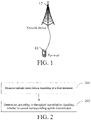
- FIG. 1 is a structural diagram of a network system to which an embodiment of the present disclosure is applicable.
- a terminal 11 and a network device 12 are included.
- the terminal 11 may be a user terminal or another terminal-side device, for example, a terminal-side device such as a mobile phone, a tablet personal computer (Tablet Personal Computer), a laptop computer (Laptop Computer), a personal digital assistant (personal digital assistant, PDA), a mobile Internet device (Mobile Internet Device, MID), or a wearable device (Wearable Device).
- a specific type of the terminal 11 is not limited in the embodiments of the present disclosure.
- the network device 12 may be a 5G base station, a base station of a later version, or a base station in another communication system, or may be referred to as a NodeB, an evolved NodeB, a transmission reception point (Transmission Reception Point, TRP), an access point (Access Point, AP), or another term in the field as long as a same technical effect is achieved.
- the network device is not limited to a specific technical term.
- the network device 12 may be a master node (Master Node, MN) or a secondary node (Secondary Node, SN). It should be noted that only the 5G base station is used as an example in the embodiments of the present disclosure, but a specific type of the network device is not limited.
- FIG. 2 is a flowchart of an uplink transmission control method according to an embodiment of the present disclosure. The method is applied to a terminal, and as shown in FIG. 2 , includes following steps:
- An interval between the first moment and a second moment of sending the uplink transmission is greater than or equal to a preset time length, and the first moment is before the second moment.
- the foregoing uplink cancellation signaling may be used to indicate cancellation of a resource for uplink transmission. Specifically, in a case that the terminal detects uplink cancellation signaling at a first moment, the terminal cancels uplink transmission if a resource indicated by the uplink cancellation signaling overlaps the uplink transmission, and skips canceling the uplink transmission if the resource indicated by the uplink cancellation signaling does not overlap the uplink transmission.
- the terminal skips canceling the uplink transmission.
- the foregoing uplink cancellation signaling may be understood as an uplink cancellation instruction, an uplink cancellation indication, or the like.
- the foregoing monitoring may be understood as monitoring, interception, detection, checking, and the like.
- a magnitude of the interval between the first moment and the second moment may be set according to actual needs.
- the preset time length is a minimum processing time for the terminal to cancel the uplink transmission. Because the interval between the first moment and the second moment of performing uplink transmission is set to be greater than or equal to a minimum processing time for canceling the uplink transmission, it can be ensured that the terminal, when monitoring uplink cancellation signaling and determining to cancel the uplink transmission based on the uplink cancellation signaling, has enough time to respond to the uplink cancellation signaling and perform the operation of canceling the uplink transmission.
- this embodiment can ensure that the terminal has enough time to perform uplink cancellation signaling and does not continue monitoring uplink cancellation signaling between the first moment and the second moment while avoiding ineffective monitoring caused by that the uplink transmission cannot be canceled even if the uplink cancellation signaling is detected, thereby saving a quantity of electricity of the terminal.
- the uplink transmission may be dynamically scheduled uplink transmission or higher level-configured uplink transmission, and may specifically include any one of physical uplink shared channel (Physical Uplink Shared Channel, PUSCH) transmission, physical uplink control channel (Physical Uplink Control Channel, PUCCH), or sounding reference signal (Sounding Reference Signal, SRS) transmission.
- Physical Uplink shared channel Physical Uplink Shared Channel
- PUCCH Physical Uplink Control Channel
- SRS Sounding Reference Signal
- uplink cancellation signaling is monitored at a first moment; and whether to cancel corresponding uplink transmission is determined according to the uplink cancellation signaling, where an interval between the first moment and a second moment of sending the uplink transmission is greater than or equal to a preset time length, and the first moment is before the second moment.
- the embodiments of the present disclosure can effectively reduce the power consumption of the terminal.
- the definition of the second moment may be set according to actual needs.
- the second moment includes any one of the following moments:
- the second moment includes any one of the following moments:
- the preset time length may be agreed on in a protocol or may be configured by the network device.
- the preset time length may include N time units, where N is a positive integer.
- the time unit includes one of a slot, a subframe, a symbol, a sub-slot, or a symbol group.
- the network device configures a first physical downlink control channel (Physical downlink control channel, PDCCH) monitoring occasion (monitoring occasion) for the terminal to monitor the uplink cancellation signaling at the first moment
- the terminal monitors the uplink cancellation signaling at the first moment.
- the terminal may perform monitoring in a period of time before the first moment, which is described below in detail.
- the method before the monitoring uplink cancellation signaling at a first moment, the method further includes: receiving configuration information sent by a network device, where the configuration information is used for configuring a first PDCCH monitoring occasion, and the first PDCCH monitoring occasion is used for monitoring the uplink cancellation signaling at the first moment.
- the configuration information may alternatively be used for configuring another parameter, for example, configuring a PDCCH monitoring occasion at another moment.
- the uplink cancellation signaling can be monitored at the first PDCCH monitoring occasion and does not need to be monitored at another moment, thereby effectively reducing the time length during which the terminal monitors the uplink cancellation signaling. Therefore, the power consumption of the terminal is reduced.
- the first PDCCH monitoring occasion may include a period of time. The first moment is included in the period of time. In other words, in this embodiment, monitoring the uplink cancellation signaling at the first moment may be understood as monitoring the uplink cancellation signaling at the first PDCCH monitoring occasion corresponding to the first moment.
- the uplink cancellation signaling is monitored before the first moment in a case that a first PDCCH monitoring occasion is not configured, where the first PDCCH monitoring occasion is used for monitoring the uplink cancellation signaling at the first moment.
- the monitoring the uplink cancellation signaling before the first moment includes any one of the following:
- the uplink cancellation signaling may be monitored at a PDCCH monitoring occasion closest to the first PDCCH monitoring occasion in monitoring occasions before the first moment.
- the uplink cancellation signaling may be monitored at any one or more PDCCH monitoring occasions before the first moment.
- the uplink cancellation signaling may alternatively be monitored at all PDCCH monitoring occasions in a period of time before the first moment.
- the third moment is a sending moment of target downlink control information (Downlink Control Information, DCI), where the target DCI is used for scheduling the uplink transmission.
- DCI Downlink Control Information
- the uplink cancellation signaling is monitored only between the sending moment of the target DCI and the first moment, the time length of monitoring can be effectively reduced, thereby reducing the power consumption of the terminal.
- a time interval between the third moment and the sending moment of the target DCI is equal to a preset PDCCH processing time.
- the third moment is an end moment of a PDCCH carrying the target DCI.
- the PDCCH processing time may be agreed on in a protocol or may be configured by the network device, and is not further limited herein. Because the PDCCH processing time is excluded, the time length during which the terminal performs monitoring is further shortened, thereby further reducing the power consumption of the terminal.
- the third moment is a position after the end moment of a PDCCH carrying the target DCI, where an interval between the third moment and the end moment is the preset PDCCH processing time.
- the terminal monitors uplink cancellation signaling at a moment t-X.
- modes in which the terminal monitors the uplink cancellation signaling include:
- X is agreed on in a protocol or configured by the network device.
- X is in a time unit of a slot, a subframe, a symbol, a sub-slot, or a symbol group. Further, X is a minimum processing time for canceling the uplink transmission.
- the terminal monitors uplink cancellation signaling on a PDCCH at X symbols before a starting position of the slot n.
- the terminal if the terminal sends a PUSCH at symbols #9 to 13 of a slot n, and the slot n includes sub-slots #0 to 3, the terminal monitors uplink cancellation signaling on a PDCCH at X symbols before a starting position of the sub-slot #2.
- the terminal monitors uplink cancellation signaling on PDCCHs at X symbols before a starting position of the time region #k.
- the terminal if the terminal sends a PUSCH at symbols #7 to 13 of a slot n, and reference moments configured by the network device in the slot are #0, 3, 6, and 9, the terminal monitors uplink cancellation signaling on a PDCCH at X symbols before the symbol #6.
- the terminal if the terminal sends a PUSCH at symbols #4 to 13 of a slot n, the terminal monitors uplink cancellation signaling on a PDCCH at X symbols before a starting position of the slot n. If the network device does not configure a PDCCH monitoring occasion for monitoring uplink cancellation signaling at a moment X symbols before the slot n, the terminal monitors the uplink cancellation signaling at a PDCCH monitoring occasion closest to and before X symbols of the slot n.
- the terminal before monitoring the uplink cancellation signaling, the terminal may receive the following configuration information from the network device:
- the terminal may determine a frequency domain indication granularity according to the time domain indication granularity and a correspondence in Table 1 below.
- the terminal before monitoring the uplink cancellation signaling, the terminal may receive the following configuration information from the network device:
- the terminal may determine a frequency domain indication granularity according to the time domain indication granularity and a correspondence in Table 2 below.
- the terminal before monitoring the uplink cancellation signaling, the terminal may receive the following configuration information from the network device:
- the terminal may determine a frequency domain indication granularity according to the time domain indication granularity and a correspondence in Table 3 below.
- the terminal before monitoring the uplink cancellation signaling, the terminal may receive the following configuration information from the network device:
- the terminal may determine a frequency domain indication granularity according to the time domain indication granularity and a correspondence in Table 4 below.
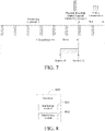
- FIG. 8 is a structural diagram of a terminal according to an embodiment of the present disclosure. As shown in FIG. 8 , a terminal 800 includes:
- An interval between the first moment and a second moment of sending the uplink transmission is greater than or equal to a preset time length, and the first moment is before the second moment.
- the second moment includes any one of the following moments:
- the preset time length is a minimum processing time for the terminal to cancel the uplink transmission.
- the terminal 800 further includes: a receiving module, configured to receive configuration information sent by a network device, where the configuration information is used for configuring a first physical downlink control channel (PDCCH) monitoring occasion, and the first PDCCH monitoring occasion is used for monitoring the uplink cancellation signaling at the first moment.
- a receiving module configured to receive configuration information sent by a network device, where the configuration information is used for configuring a first physical downlink control channel (PDCCH) monitoring occasion, and the first PDCCH monitoring occasion is used for monitoring the uplink cancellation signaling at the first moment.
- a receiving module configured to receive configuration information sent by a network device, where the configuration information is used for configuring a first physical downlink control channel (PDCCH) monitoring occasion, and the first PDCCH monitoring occasion is used for monitoring the uplink cancellation signaling at the first moment.
- PDCCH physical downlink control channel
- the monitoring module 801 is further configured to monitor, in a case that a first PDCCH monitoring occasion is not configured, the uplink cancellation signaling before the first moment, where the first PDCCH monitoring occasion is used for monitoring the uplink cancellation signaling at the first moment.
- the monitoring module 801 is further configured to perform any one of the following:
- the third moment is a sending moment of target downlink control information (DCI), where the target DCI is used for scheduling the uplink transmission; or a time interval between the third moment and the sending moment of the target DCI is equal to a preset PDCCH processing time.
- DCI downlink control information
- the preset time length includes N time units, where N is a positive integer; and the time unit includes one of a slot, a subframe, a symbol, a sub-slot, or a symbol group.
- the terminal provided in this embodiment of the present disclosure can implement various processes implemented by the terminal in the method embodiment of FIG. 2 . To avoid repetition, details are not described herein again.
- FIG. 9 is a schematic diagram of a hardware structure of a terminal according to respective embodiments of the present disclosure.
- the terminal 900 includes, but is not limited to, components such as a radio frequency unit 901, a network module 902, an audio output unit 903, an input unit 904, a sensor 905, a display unit 906, a user input unit 907, an interface unit 908, a memory 909, a processor 910, and a power supply 911.
- components such as a radio frequency unit 901, a network module 902, an audio output unit 903, an input unit 904, a sensor 905, a display unit 906, a user input unit 907, an interface unit 908, a memory 909, a processor 910, and a power supply 911.
- a terminal structure shown in FIG. 9 constitutes no limitation on the terminal, and the terminal may include more or fewer components than those shown in the figure, or some components may be combined, or a different component deployment may be used.
- the method includes, but is not limited to, a mobile phone, a tablet computer, a notebook computer, a palmtop computer, an in-vehicle terminal, a wearable terminal, a pedometer, and the like.
- the radio frequency unit 901 is configured to monitor uplink cancellation signaling at a first moment.
- the processor 910 is configured to determine, according to the uplink cancellation signaling, whether to cancel corresponding uplink transmission.
- An interval between the first moment and a second moment of sending the uplink transmission is greater than or equal to a preset time length, and the first moment is before the second moment.
- the processor 910 and the radio frequency unit 901 can implement various processes implemented by the terminal in the method embodiment of FIG. 2 . To avoid repetition, details are not described herein again.
- the radio frequency unit 901 may be configured to receive and transmit information or receive and transmit signals during a call. Specifically, after being received, downlink data from a base station is processed by the processor 910. In addition, uplink data is sent to the base station.
- the radio frequency unit 901 includes, but is not limited to, an antenna, at least one amplifier, a transceiver, a coupler, a low noise amplifier, a duplexer, and the like. In addition, the radio frequency unit 901 may further communicate with another device through a wireless communication system and network.
- the terminal provides wireless broadband Internet access for a user through the network module 902, for example, help the user to send and receive emails, browse webpages, and access stream media, and the like.
- the audio output unit 903 may convert audio data received by the radio frequency unit 901 or network module 902 or audio data stored on the memory 909 into audio signals and output the audio signals as sounds. Moreover, the audio output unit 903 may further provide an audio output (for example, a call signal receiving sound or a message receiving sound) related to a specific function implemented by the terminal 900.
- the audio output unit 903 includes a speaker, a buzzer, a receiver, and the like.
- the input unit 904 is configured to receive an audio signal or a video signal.
- the input unit 904 may include a graphics processing unit (Graphics Processing Unit, GPU) 9041 and a microphone 9042.
- the graphics processing unit 9041 processes image data of a static picture or a video obtained by an image capturing apparatus (for example, a camera) in a video capturing mode or an image capturing mode.
- An image frame that has been processed may be displayed on a display unit 906.
- the image frame that has been processed by the graphics processing unit 9041 may be stored on the memory 909 (or another storage medium) or sent by using the radio frequency unit 901 or network module 902.
- the microphone 9042 may receive a sound, and can process the sound into audio data.
- the processed audio data may be converted, in a phone call mode, into a format that may be sent to a mobile communication base station via the radio frequency unit 901 and be output.
- the terminal 900 further includes at least one sensor 905 such as an optical sensor, a motion sensor, and another sensor.
- the optical sensor includes an ambient light sensor and a proximity sensor.
- the ambient light sensor may adjust luminance of the display panel 9061 according to the luminance of the ambient light
- the proximity sensor may switch off the display panel 9061 and/or backlight when the terminal 900 is moved to the ear.
- an acceleration sensor can monitor magnitudes of accelerations in various directions (generally, on three axes), may detect a magnitude and a direction of the gravity in a static state, and may be applied to recognizing an attitude of the terminal (for example, switching between landscape orientation and portrait orientation, a related game, and magnetometer attitude calibration), a function related to vibration recognition (such as a pedometer and a knock), and the like.
- the sensor 905 may further include a fingerprint sensor, a pressure sensor, an iris sensor, a molecular sensor, a gyroscope, a barometer, a hygrometer, a thermometer, an infrared sensor, and the like, and details are not described herein.
- the display unit 906 is configured to display information entered by the user or information provided for the user.
- the display unit 906 may include a display panel 9061.
- the display panel 9061 may be configured in a form of a liquid crystal display (LCD), an organic light-emitting diode (OLED), or the like.
- the user input unit 907 may be configured to receive input digit or character information, and generate key signal input related to the user setting and function control of the terminal.
- the user input unit 907 includes a touch panel 9071 and another input device 9072.
- the touch panel 9071 also referred to as a touchscreen, may collect a touch operation of a user on or near the touch panel (such as an operation of a user on or near the touch panel 9071 by using any suitable object or attachment, such as a finger or a touch pen).
- the touch panel 9071 may include two parts: a touch monitoring apparatus and a touch controller.
- the touch monitoring apparatus monitors a touch orientation of the user, monitors a signal brought by the touch operation, and transmits the signal to the touch controller.
- the touch controller receives touch information from the touch monitoring apparatus, converts the touch information into a contact coordinate, then transmits the contact coordinate to the processor 910, and receives and executes a command transmitted by the processor 910.
- the touch panel 9071 may be implemented by using various types, such as a resistive type, a capacitive type, an infrared type, and a surface acoustic wave type.
- the user input unit 907 may further include the another input device 9072.
- the another input device 9072 may include, but not limited to, a physical keyboard, a functional key (such as a volume control key or a switch key), a track ball, a mouse, and a joystick, which is not described herein in detail.
- the touch panel 9071 may cover the display panel 9061. After detecting a touch operation on or near the touch panel 9071, the touch panel transfers the touch operation to the processor 910, so as to determine a type of the touch event. Then, the processor 910 provides corresponding visual output on the display panel 9061 according to the type of the touch event.
- the touch panel 9071 and the display panel 9061 are used as two separate parts to implement input and output functions of the terminal, in some embodiments, the touch panel 9071 and the display panel 9061 may be integrated to implement the input and output functions of the terminal. Details are not limited herein.
- the interface unit 908 is an interface between an external apparatus and the terminal 900.
- the external apparatus may include a wired or wireless headset port, an external power supply (or a battery charger) port, a wired or wireless data port, a storage card port, a port used to connect an apparatus having an identification module, an audio input/output (I/O) port, a video I/O port, an earphone port, and the like.
- the interface unit 908 may be configured to receive an input (such as data information or electric power) from an external apparatus and transmit the received input to one or more elements in the terminal 900 or may be configured to transmit data between the terminal 900 and the external apparatus.
- the memory 909 may be configured to store a software program and various data.
- the memory 909 may mainly include a program storage area and a data storage area.
- the program storage area may store an operating system, an application required by at least one function (for example, a sound playback function or an image playback function), and the like.
- the data storage area may store data (for example, audio data and a phone book) created according to use of the mobile phone.
- the memory 909 may include a high speed random access memory, and may further include a non-volatile memory, such as at least one magnetic disk storage device, a flash memory device, or other non-volatile solid state storage devices.
- the processor 910 is the control center of the terminal, and is connected to various parts of the terminal by using various interfaces and lines. By running or executing the software program and/or module stored in the memory 909, and invoking data stored in the memory 909, the processor 910 performs various functions and data processing of the terminal, thereby performing overall monitoring on the terminal.
- the processor 910 may include one or more processing units.
- the processor 910 may integrate an application processor and a modem processor.
- the application processor mainly processes an operating system, a user interface, an application program, and the like, and the modem processor mainly processes wireless communication. It may be understood that the modulation and demodulation processor may not be integrated into the processor 910.
- the terminal 900 further includes the power supply 911 (such as a battery) for supplying power to the components.
- the power supply 911 may be logically connected to the processor 910 by a power management system, thereby implementing functions, such as charging, discharging, and power consumption management, by using the power management system.
- the terminal 900 includes some function modules that are not shown, which is not described herein in detail.
- the embodiments of the present disclosure further provide a terminal, including a processor 910, a memory 909, and a computer program stored on the memory 909 and executable on the processor 910, where when executed by the processor 910, the computer program implements respective processes of the embodiments of the uplink transmission control method, and can achieve the same technical effects. To avoid repetition, details are not described herein again.
- the embodiments of the present disclosure further provide a computer-readable storage medium, storing a computer program, where when executed by a processor, the computer program implements respective processes of the embodiments of the uplink transmission control method on a terminal side provided by the embodiments of the present disclosure, and can achieve the same technical effects. To avoid repetition, details are not described herein again.
- the computer-readable storage medium may include a read-only memory (ROM), a random access memory (RAM), a magnetic disk, and an optical disc.
- the foregoing embodiment methods may be implemented by using software in combination with a necessary universal hardware platform.
- the embodiment methods may also be implemented by using hardware, but the former is a better implementation in many cases.
- the technical solutions of the present disclosure essentially or the part contributing to the related technology may be implemented in a form of a software product.
- the computer software product is stored in a storage medium (such as a ROM/RAM, a magnetic disk, or an optical disc) and includes several instructions for instructing a terminal device (which may be a mobile phone, a computer, a server, an air conditioner, a base station, or the like) to perform the methods described in the embodiments of the present disclosure.
Landscapes
- Engineering & Computer Science (AREA)
- Computer Networks & Wireless Communication (AREA)
- Signal Processing (AREA)
- Mobile Radio Communication Systems (AREA)
Applications Claiming Priority (2)
| Application Number | Priority Date | Filing Date | Title |
|---|---|---|---|
| CN201910968935.1A CN112654078B (zh) | 2019-10-12 | 2019-10-12 | 一种上行传输控制方法及终端 |
| PCT/CN2020/119899 WO2021068875A1 (zh) | 2019-10-12 | 2020-10-09 | 上行传输控制方法及终端 |
Publications (2)
| Publication Number | Publication Date |
|---|---|
| EP4044690A1 true EP4044690A1 (de) | 2022-08-17 |
| EP4044690A4 EP4044690A4 (de) | 2022-11-23 |
Family
ID=75343306
Family Applications (1)
| Application Number | Title | Priority Date | Filing Date |
|---|---|---|---|
| EP20874160.3A Pending EP4044690A4 (de) | 2019-10-12 | 2020-10-09 | Verfahren zur steuerung der uplink-übertragung und endgerät |
Country Status (6)
| Country | Link |
|---|---|
| US (1) | US12250628B2 (de) |
| EP (1) | EP4044690A4 (de) |
| KR (1) | KR102857336B1 (de) |
| CN (1) | CN112654078B (de) |
| BR (1) | BR112022006247A2 (de) |
| WO (1) | WO2021068875A1 (de) |
Families Citing this family (6)
| Publication number | Priority date | Publication date | Assignee | Title |
|---|---|---|---|---|
| CN114467355B (zh) * | 2019-10-04 | 2025-06-13 | Lg电子株式会社 | 监测上行链路取消指令的方法、用户设备、装置、计算机可读存储介质、发送上行链路取消指令的方法和基站 |
| CN112654078B (zh) * | 2019-10-12 | 2022-10-14 | 维沃移动通信有限公司 | 一种上行传输控制方法及终端 |
| CN114731639B (zh) * | 2019-11-18 | 2024-10-11 | 中兴通讯股份有限公司 | 用于确定指示取消的信息的系统和方法 |
| CN114698130B (zh) * | 2020-12-25 | 2025-07-18 | 展讯半导体(南京)有限公司 | 无线通信方法与装置、终端和网络设备 |
| EP4275319A2 (de) * | 2021-01-05 | 2023-11-15 | Ofinno, LLC | Schlitzkonfiguration bei steuerkanalwiederholung |
| CN115334661A (zh) * | 2021-05-11 | 2022-11-11 | 中兴通讯股份有限公司 | 通信方法、设备和存储介质 |
Family Cites Families (40)
| Publication number | Priority date | Publication date | Assignee | Title |
|---|---|---|---|---|
| US9467975B2 (en) * | 2014-09-29 | 2016-10-11 | Qualcomm Incorporated | System and methods for cancelling uplink traffic channel bursts to improve performance in a multi-SIM wireless communication device |
| WO2017217799A1 (ko) * | 2016-06-16 | 2017-12-21 | 엘지전자 주식회사 | 무선 통신 시스템에서 물리 상향링크 제어 채널 송수신 방법 및 이를 지원하는 장치 |
| KR102603814B1 (ko) * | 2017-01-06 | 2023-11-17 | 한국전자통신연구원 | 상향링크 제어정보 전송 방법 및 장치 |
| CN108282883B (zh) * | 2017-01-06 | 2020-03-24 | 电信科学技术研究院 | 一种信息传输方法及装置 |
| CN108347325B (zh) * | 2017-01-25 | 2021-08-20 | 华为技术有限公司 | 一种信息传输方法及装置 |
| CN110574473A (zh) * | 2017-03-02 | 2019-12-13 | 株式会社Ntt都科摩 | 用户终端以及无线通信方法 |
| CN109462892B (zh) * | 2017-06-30 | 2019-11-19 | 华为技术有限公司 | 控制信息传输方法和设备 |
| KR102338507B1 (ko) * | 2017-08-04 | 2021-12-13 | 삼성전자 주식회사 | 무선 통신 시스템에서 하향링크 제어정보를 송수신하는 방법 및 장치 |
| US11272546B2 (en) * | 2017-08-08 | 2022-03-08 | Samsung Electronics Co., Ltd. | Methods and apparatus for transmitting and receiving uplink control information and for requesting random access in wireless communication system |
| US10819470B2 (en) * | 2018-01-12 | 2020-10-27 | Intel IP Corporation | Behavior of user equipment (UE) in scenarios of conflicting resource assignments in new radio (NR) systems |
| US10820342B2 (en) * | 2018-02-13 | 2020-10-27 | Mediatek Singapore Pte. Ltd. | Method and apparatus for flexible scheduling of uplink transmissions in mobile communications |
| WO2019160332A1 (ko) * | 2018-02-14 | 2019-08-22 | 주식회사 케이티 | 상향링크 데이터를 전송하는 방법 및 장치 |
| US11039464B2 (en) * | 2018-02-15 | 2021-06-15 | Apple Inc. | Simultaneous HARQ-ACK feedback and uplink transmission without dynamic grant |
| CN110366245B (zh) * | 2018-03-26 | 2021-11-02 | 维沃移动通信有限公司 | 取消上行传输的方法和设备 |
| CN110324846B (zh) * | 2018-03-28 | 2021-09-03 | 维沃移动通信有限公司 | 一种上行传输取消指令的监听方法及终端 |
| EP3547780B1 (de) * | 2018-03-30 | 2022-02-16 | Comcast Cable Communications LLC | Drahtlose kommunikation für uplink-bevorrechtigung und downlink-bevorrechtigung |
| WO2019190265A1 (ko) * | 2018-03-30 | 2019-10-03 | 주식회사 케이티 | 상향링크 데이터 채널 전송 전력 제어 방법 및 장치 |
| ES2989693T3 (es) * | 2018-04-04 | 2024-11-27 | Zte Corp | Métodos y aparato para apropiarse de un recurso de transmisión de enlace ascendente en una comunicación inalámbrica |
| WO2019191999A1 (zh) * | 2018-04-04 | 2019-10-10 | 华为技术有限公司 | 一种资源确定方法、指示方法及装置 |
| US11051357B2 (en) * | 2018-04-05 | 2021-06-29 | Qualcomm Incorporated | Cancellation policy for radio resource control configured uplink transmissions |
| WO2019194664A1 (ko) * | 2018-04-06 | 2019-10-10 | 엘지전자 주식회사 | 무선 통신 시스템에서 데이터를 송수신하기 위한 방법 및 이를 위한 장치 |
| EP3782434B1 (de) * | 2018-04-20 | 2023-10-04 | ZTE Corporation | Vorrichtung und verfahren für mobilitätsverwaltung |
| JP7066503B2 (ja) * | 2018-04-27 | 2022-05-13 | シャープ株式会社 | 基地局装置および端末装置 |
| SG11202010604RA (en) * | 2018-04-28 | 2020-11-27 | Beijing Xiaomi Mobile Software Co Ltd | Uplink transmission method and apparatus |
| WO2020006027A1 (en) * | 2018-06-29 | 2020-01-02 | Sharp Laboratories Of America, Inc. | Ultra-reliability design for physical uplink control channel (pucch) in 5th generation (5g) new radio (nr) |
| KR102677346B1 (ko) * | 2018-08-10 | 2024-06-20 | 지티이 코포레이션 | 제어 정보 송신 기법 |
| KR20210045426A (ko) * | 2018-08-17 | 2021-04-26 | 광동 오포 모바일 텔레커뮤니케이션즈 코포레이션 리미티드 | 통신 방법, 단말기 디바이스 및 네트워크 디바이스 |
| KR102902581B1 (ko) * | 2018-11-09 | 2025-12-19 | 한국전자통신연구원 | 높은 신뢰 조건을 가지는 데이터 또는 제어 정보의 전송 방법 및 이를 위한 장치 |
| US12232126B2 (en) * | 2019-04-02 | 2025-02-18 | Apple Inc. | Resource allocation for repeated uplink transmissions |
| US12250694B2 (en) * | 2019-05-03 | 2025-03-11 | Apple Inc. | Downlink control channel signaling for UL coexistence of multiple service types |
| US11419123B2 (en) * | 2019-05-03 | 2022-08-16 | Qualcomm Incorporated | Uplink transmission cancellation |
| US11452167B2 (en) * | 2019-05-08 | 2022-09-20 | Qualcomm Incorporated | Methods and apparatus to selectively monitor uplink preemptive indication for supplementary uplink and non-supplementary uplink carriers |
| CN114175825B (zh) * | 2019-08-01 | 2025-02-25 | 高通股份有限公司 | 用于基于全双工的iab的上行链路抢占指示 |
| CN111835483B (zh) * | 2019-08-08 | 2022-07-08 | 维沃移动通信有限公司 | 一种信息传输方法及电子设备 |
| CN112566146B (zh) * | 2019-09-25 | 2022-04-12 | 维沃移动通信有限公司 | 一种上行传输方法及终端 |
| WO2021056528A1 (en) * | 2019-09-29 | 2021-04-01 | Zte Corporation | Systems and methods for transmitting signals |
| GB2587665A (en) * | 2019-10-04 | 2021-04-07 | Nec Corp | Communication system |
| CN112654078B (zh) * | 2019-10-12 | 2022-10-14 | 维沃移动通信有限公司 | 一种上行传输控制方法及终端 |
| EP4088529A4 (de) * | 2020-01-09 | 2023-10-04 | Qualcomm Incorporated | Uplink-vorbelegung für multislot-uci-multiplexing |
| CN115087121B (zh) * | 2021-03-12 | 2025-09-16 | 维沃移动通信有限公司 | Cot确定方法、上行传输方法和设备 |
-
2019
- 2019-10-12 CN CN201910968935.1A patent/CN112654078B/zh active Active
-
2020
- 2020-10-09 EP EP20874160.3A patent/EP4044690A4/de active Pending
- 2020-10-09 KR KR1020227015724A patent/KR102857336B1/ko active Active
- 2020-10-09 WO PCT/CN2020/119899 patent/WO2021068875A1/zh not_active Ceased
- 2020-10-09 BR BR112022006247A patent/BR112022006247A2/pt unknown
-
2022
- 2022-04-12 US US17/719,165 patent/US12250628B2/en active Active
Also Published As
| Publication number | Publication date |
|---|---|
| KR20220080167A (ko) | 2022-06-14 |
| CN112654078A (zh) | 2021-04-13 |
| KR102857336B1 (ko) | 2025-09-08 |
| CN112654078B (zh) | 2022-10-14 |
| BR112022006247A2 (pt) | 2022-06-21 |
| US12250628B2 (en) | 2025-03-11 |
| WO2021068875A1 (zh) | 2021-04-15 |
| US20220240181A1 (en) | 2022-07-28 |
| EP4044690A4 (de) | 2022-11-23 |
Similar Documents
| Publication | Publication Date | Title |
|---|---|---|
| US12250628B2 (en) | Uplink transmission control method and terminal | |
| US12035242B2 (en) | PDCCH monitoring method and terminal | |
| EP3742845A1 (de) | Zellverarbeitungsverfahren, endgerätevorrichtung und netzwerkvorrichtung | |
| US12446034B2 (en) | Transmission method, configuration method, terminal, and network-side device | |
| US12075474B2 (en) | Transmission time indication method for unlicensed band, network device and terminal | |
| US12520240B2 (en) | Information transmission method and terminal | |
| US20220217708A1 (en) | Uplink transmission method and terminal | |
| US12185357B2 (en) | Prioritized resource overlap transmission method according to dci, terminal, and network side device | |
| WO2021027713A1 (zh) | 上行传输方法、上行传输控制方法及相关设备 | |
| WO2020073805A1 (zh) | 上行传输的指示方法、终端及网络侧设备 | |
| WO2021018130A1 (zh) | 物理上行链路控制信道传输方法、装置、设备及介质 | |
| US12513618B2 (en) | Method for secondary cell dormancy indication and communication device | |
| US20230034859A1 (en) | Method for determining conflicting resource, terminal, and network device | |
| US20210219247A1 (en) | Power headroom reporting method and terminal device | |
| US11570724B2 (en) | Method for PH calculation and terminal | |
| HK40063757A (en) | Pdcch monitoring method and terminal | |
| HK40069052A (en) | Uplink transmission method and terminal | |
| WO2020147812A1 (zh) | 数据反馈信息处理方法、装置、移动终端及存储介质 | |
| CN111435908A (zh) | 信道处理方法、装置、终端设备及介质 |
Legal Events
| Date | Code | Title | Description |
|---|---|---|---|
| STAA | Information on the status of an ep patent application or granted ep patent |
Free format text: STATUS: THE INTERNATIONAL PUBLICATION HAS BEEN MADE |
|
| PUAI | Public reference made under article 153(3) epc to a published international application that has entered the european phase |
Free format text: ORIGINAL CODE: 0009012 |
|
| STAA | Information on the status of an ep patent application or granted ep patent |
Free format text: STATUS: REQUEST FOR EXAMINATION WAS MADE |
|
| 17P | Request for examination filed |
Effective date: 20220511 |
|
| AK | Designated contracting states |
Kind code of ref document: A1 Designated state(s): AL AT BE BG CH CY CZ DE DK EE ES FI FR GB GR HR HU IE IS IT LI LT LU LV MC MK MT NL NO PL PT RO RS SE SI SK SM TR |
|
| A4 | Supplementary search report drawn up and despatched |
Effective date: 20221024 |
|
| RIC1 | Information provided on ipc code assigned before grant |
Ipc: H04W 24/00 20090101ALI20221018BHEP Ipc: H04W 72/04 20090101ALI20221018BHEP Ipc: H04W 52/02 20090101AFI20221018BHEP |
|
| DAV | Request for validation of the european patent (deleted) | ||
| DAX | Request for extension of the european patent (deleted) | ||
| REG | Reference to a national code |
Ref country code: DE Ref legal event code: R079 Free format text: PREVIOUS MAIN CLASS: H04W0052020000 Ipc: H04W0072210000 |
|
| GRAP | Despatch of communication of intention to grant a patent |
Free format text: ORIGINAL CODE: EPIDOSNIGR1 |
|
| STAA | Information on the status of an ep patent application or granted ep patent |
Free format text: STATUS: GRANT OF PATENT IS INTENDED |
|
| RIC1 | Information provided on ipc code assigned before grant |
Ipc: H04W 72/21 20230101AFI20251111BHEP Ipc: H04W 52/02 20090101ALI20251111BHEP Ipc: H04W 72/04 20090101ALI20251111BHEP Ipc: H04W 24/00 20090101ALI20251111BHEP Ipc: H04W 72/0446 20230101ALI20251111BHEP |
|
| INTG | Intention to grant announced |
Effective date: 20251126 |
|
| GRAJ | Information related to disapproval of communication of intention to grant by the applicant or resumption of examination proceedings by the epo deleted |
Free format text: ORIGINAL CODE: EPIDOSDIGR1 |
|
| STAA | Information on the status of an ep patent application or granted ep patent |
Free format text: STATUS: REQUEST FOR EXAMINATION WAS MADE |
|
| GRAP | Despatch of communication of intention to grant a patent |
Free format text: ORIGINAL CODE: EPIDOSNIGR1 |
|
| STAA | Information on the status of an ep patent application or granted ep patent |
Free format text: STATUS: GRANT OF PATENT IS INTENDED |
|
| INTC | Intention to grant announced (deleted) |