EP4044681A1 - Qos control method and apparatus, and readable storage medium - Google Patents
Qos control method and apparatus, and readable storage medium Download PDFInfo
- Publication number
- EP4044681A1 EP4044681A1 EP20919810.0A EP20919810A EP4044681A1 EP 4044681 A1 EP4044681 A1 EP 4044681A1 EP 20919810 A EP20919810 A EP 20919810A EP 4044681 A1 EP4044681 A1 EP 4044681A1
- Authority
- EP
- European Patent Office
- Prior art keywords
- information
- qos
- terminal device
- qos information
- requirement
- Prior art date
- Legal status (The legal status is an assumption and is not a legal conclusion. Google has not performed a legal analysis and makes no representation as to the accuracy of the status listed.)
- Pending
Links
Images


Classifications
-
- H—ELECTRICITY
- H04—ELECTRIC COMMUNICATION TECHNIQUE
- H04W—WIRELESS COMMUNICATION NETWORKS
- H04W28/00—Network traffic management; Network resource management
- H04W28/02—Traffic management, e.g. flow control or congestion control
- H04W28/0268—Traffic management, e.g. flow control or congestion control using specific QoS parameters for wireless networks, e.g. QoS class identifier [QCI] or guaranteed bit rate [GBR]
-
- H—ELECTRICITY
- H04—ELECTRIC COMMUNICATION TECHNIQUE
- H04B—TRANSMISSION
- H04B17/00—Monitoring; Testing
- H04B17/30—Monitoring; Testing of propagation channels
- H04B17/309—Measuring or estimating channel quality parameters
-
- H—ELECTRICITY
- H04—ELECTRIC COMMUNICATION TECHNIQUE
- H04W—WIRELESS COMMUNICATION NETWORKS
- H04W28/00—Network traffic management; Network resource management
- H04W28/16—Central resource management; Negotiation of resources or communication parameters, e.g. negotiating bandwidth or QoS [Quality of Service]
- H04W28/24—Negotiating SLA [Service Level Agreement]; Negotiating QoS [Quality of Service]
-
- H—ELECTRICITY
- H04—ELECTRIC COMMUNICATION TECHNIQUE
- H04W—WIRELESS COMMUNICATION NETWORKS
- H04W4/00—Services specially adapted for wireless communication networks; Facilities therefor
- H04W4/50—Service provisioning or reconfiguring
-
- H—ELECTRICITY
- H04—ELECTRIC COMMUNICATION TECHNIQUE
- H04W—WIRELESS COMMUNICATION NETWORKS
- H04W40/00—Communication routing or communication path finding
- H04W40/02—Communication route or path selection, e.g. power-based or shortest path routing
- H04W40/12—Communication route or path selection, e.g. power-based or shortest path routing based on transmission quality or channel quality
-
- H—ELECTRICITY
- H04—ELECTRIC COMMUNICATION TECHNIQUE
- H04W—WIRELESS COMMUNICATION NETWORKS
- H04W88/00—Devices specially adapted for wireless communication networks, e.g. terminals, base stations or access point devices
- H04W88/02—Terminal devices
- H04W88/04—Terminal devices adapted for relaying to or from another terminal or user
-
- H—ELECTRICITY
- H04—ELECTRIC COMMUNICATION TECHNIQUE
- H04W—WIRELESS COMMUNICATION NETWORKS
- H04W84/00—Network topologies
- H04W84/02—Hierarchically pre-organised networks, e.g. paging networks, cellular networks, WLAN [Wireless Local Area Network] or WLL [Wireless Local Loop]
- H04W84/04—Large scale networks; Deep hierarchical networks
- H04W84/042—Public Land Mobile systems, e.g. cellular systems
-
- H—ELECTRICITY
- H04—ELECTRIC COMMUNICATION TECHNIQUE
- H04W—WIRELESS COMMUNICATION NETWORKS
- H04W92/00—Interfaces specially adapted for wireless communication networks
- H04W92/16—Interfaces between hierarchically similar devices
- H04W92/18—Interfaces between hierarchically similar devices between terminal devices
Definitions
- Implementations of this disclosure relate to the field of communication technology, and particularly to a method for quality of service (QoS) control, an apparatus, and a readable storage medium.
- QoS quality of service
- a terminal device which can interact with an external network (such as the internet, a private network of a certain industry or organization, etc.) through a 5G network and also has proximity-based services (ProSe) capability, is used as a relay terminal device, and other remote terminal devices having ProSe capability can establish a connection with the relay terminal device through a PC5 interface and establish a protocol data unit (PDU) session with the 5G network via the relay terminal device, so as to realize interaction with the external network.
- an external network such as the internet, a private network of a certain industry or organization, etc.
- ProSe proximity-based services
- Implementations of the disclosure provide a method for quality of service (QoS) control, an apparatus, and a readable storage medium, to realize the following.
- QoS quality of service
- a method for QoS control includes the following.
- a first terminal device receives first information from a second terminal device, where the first information includes an end-to-end QoS requirement of a service which is initiated by the second terminal device and to be communicated to an external network via the first terminal device.
- the first terminal device obtains first QoS information and second QoS information, where the first QoS information is QoS information of communication between the first terminal device and the second terminal device, the second QoS information is QoS information of communication between the first terminal device and the external network, and the end-to-end QoS requirement is satisfied by the first QoS information and the second QoS information.
- the method further includes the following.
- the first terminal device provides the first QoS information to the second terminal device.
- a method for QoS control includes the following.
- a second terminal device provides first information to a first terminal device, where the first information includes an end-to-end QoS requirement of a service which is initiated by the second terminal device and to be communicated to an external network via the first terminal device.
- the second terminal device receives first QoS information from the first terminal device, where the first QoS information is QoS information of communication between the first terminal device and the second terminal device.
- a method for QoS control includes the following.
- a first network device receives information used for determining second QoS information and provided by a first terminal device according to an end-to-end QoS requirement, where the end-to-end QoS requirement is an end-to-end QoS requirement of a service which is initiated by a second terminal device and to be communicated to an external network via the first terminal device.
- the first network device obtains the second QoS information according to the information used for determining the second QoS information, where the second QoS information is QoS information of communication between the first terminal device and the external network.
- the first network device provides information indicative of the second QoS information to the first terminal device.
- a method for QoS control is further provided in implementations of the disclosure.
- the method includes the following.
- a second network device receives information used for determining second QoS information from a first network device, where an end-to-end QoS requirement is an end-to-end QoS requirement of a service which is initiated by a second terminal device and to be communicated to an external network via a first terminal device.
- the second network device obtains the second QoS information according to the information used for determining the second QoS information, where the second QoS information is QoS information of communication between the first terminal device and the external network.
- the second network device provides information indicative of the second QoS information to the first network device.
- a terminal device in implementations of the disclosure.
- the terminal device is a first terminal device.
- the terminal device includes a transceiver module and a processing module.
- the transceiver module is configured to receive first information from a second terminal device, where the first information includes an end-to-end QoS requirement of a service which is initiated by the second terminal device and to be communicated to an external network via the first terminal device.
- the processing module is configured to obtain first QoS information and second QoS information.
- the first QoS information is QoS information of communication between the first terminal device and the second terminal device
- the second QoS information is QoS information of communication between the first terminal device and the external network
- the end-to-end QoS requirement is satisfied by the first QoS information and the second QoS information.
- the transceiver module is further configured to provide the first QoS information to the second terminal device.
- a terminal device in implementations of the disclosure.
- the terminal device is a second terminal device.
- the terminal device includes a transceiver module and a processing module.
- the transceiver module is configured to provide first information to a first terminal device, where the first information includes an end-to-end QoS requirement of a service which is initiated by the second terminal device and to be communicated to an external network via the first terminal device.
- the transceiver module is further configured to receive first QoS information from the first terminal device.
- the processing module is configured to obtain the first QoS information from information received.
- the first QoS information is QoS information of communication between the first terminal device and the second terminal device.
- a network device in implementations of the disclosure.
- the network device is a first network device.
- the network device includes a transceiver module and a processing module.
- the transceiver module is configured to receive information used for determining second QoS information and provided by a first terminal device according to an end-to-end QoS requirement, where the end-to-end QoS requirement is an end-to-end QoS requirement of a service which is initiated by a second terminal device and to be communicated to an external network via the first terminal device.
- the processing module is configured to obtain the second QoS information according to the information used for determining the second QoS information, where the second QoS information is QoS information of communication between the first terminal device and the external network.
- the transceiver module is further configured to provide information indicative of the second QoS information to the first terminal device.
- a network device is further provided in implementations of the disclosure.
- the network device is a second network device.
- the network device includes a transceiver module and a processing module.
- the transceiver module is configured to receive information used for determining second QoS information from a first network device, where an end-to-end QoS requirement is an end-to-end QoS requirement of a service which is initiated by a second terminal device and to be communicated to an external network via a first terminal device.
- the processing module is configured to obtain the second QoS information according to the information used for determining the second QoS information, where the second QoS information is QoS information of communication between the first terminal device and the external network.
- the transceiver module is further configured to provide information indicative of the second QoS information to the first network device.
- a terminal device is further provided in implementations of the disclosure.
- the terminal device is a first terminal device.
- the terminal device includes a processor, a memory, and an interface configured for communication with a network device.
- the memory is configured to store computer executable instructions.
- the processor is configured to execute the computer executable instructions stored in the memory, to perform the method described in any of the first aspect.
- a terminal device is further provided in implementations of the disclosure.
- the terminal device is a second terminal device.
- the terminal device includes a processor, a memory, and an interface configured for communication with a network device.
- the memory is configured to store computer executable instructions.
- the processor is configured to execute the computer executable instructions stored in the memory, to perform the method described in any of the second aspect.
- a network device is further provided in implementations of the disclosure.
- the network device is a first network device.
- the network device includes a processor, a memory, and an interface configured for communication with a network device.
- the memory is configured to store computer executable instructions.
- the processor is configured to execute the computer executable instructions stored in the memory, to perform the method described in any of the third aspect.
- a network device is further provided in implementations of the disclosure.
- the network device is a second network device.
- the network device includes a processor, a memory, and an interface configured for communication with a network device.
- the memory is configured to store computer executable instructions.
- the processor is configured to execute the computer executable instructions stored in the memory, to perform the method described in any of the fourth aspect.
- a computer-readable storage medium is further provided in implementations of the disclosure.
- the computer-readable storage medium is configured to store computer executable instructions which, when executed by a processor, are operable with the processor to perform the method described in any of the first aspect.
- a computer-readable storage medium is further provided in implementations of the disclosure.
- the computer-readable storage medium is configured to store computer executable instructions which, when executed by a processor, are operable with the processor to perform the method described in any of the second aspect.
- a computer-readable storage medium is further provided in implementations of the disclosure.
- the computer-readable storage medium is configured to store computer executable instructions which, when executed by a processor, are operable with the processor to perform the method described in any of the third aspect.
- a computer-readable storage medium is further provided in implementations of the disclosure.
- the computer-readable storage medium is configured to store computer executable instructions which, when executed by a processor, are operable with the processor to perform the method described in any of the first aspect.
- a program is further provided in implementations of the disclosure.
- the program when executed by a processor, is operable with the processor to perform the method described in any of the first aspect.
- a program is further provided in implementations of the disclosure.
- the program when executed by a processor, is operable with the processor to perform the method described in any of the second aspect.
- a program is further provided in implementations of the disclosure.
- the program when executed by a processor, is operable with the processor to perform the method described in any of the third aspect.
- a program is further provided in implementations of the disclosure.
- the program when executed by a processor, is operable with the processor to perform the method described in any of the fourth aspect.
- a computer program product is further provided in implementations of the disclosure.
- the computer program product includes program instructions.
- the program instructions implement the method described in any of the first aspect.
- a computer program product is further provided in implementations of the disclosure.
- the computer program product includes program instructions.
- the program instructions implement the method described in any of the second aspect.
- a computer program product is further provided in implementations of the disclosure.
- the computer program product includes program instructions.
- the program instructions implement the method described in any of the third aspect.
- a computer program product is further provided in implementations of the disclosure.
- the computer program product includes program instructions.
- the program instructions implement the method described in any of the fourth aspect.
- a chip is further provided in implementations of the disclosure.
- the chip includes a processing module and a communication interface.
- the processing module can be configured to perform the method described in any of the first aspect.
- the chip further includes a storage module (such as memory).
- the storage module is configured to store instructions.
- the processing module is configured to execute the instructions stored in the storage module, and execution of the instructions stored in the storage module makes the processing module perform the method described in any of the first aspect.
- a chip is further provided in implementations of the disclosure.
- the chip includes a processing module and a communication interface.
- the processing module can be configured to perform the method described in any of the second aspect.
- the chip further includes a storage module (such as memory).
- the storage module is configured to store instructions.
- the processing module is configured to execute the instructions stored in the storage module, and execution of the instructions stored in the storage module makes the processing module perform the method described in any of the second aspect.
- a chip is further provided in implementations of the disclosure.
- the chip includes a processing module and a communication interface.
- the processing module can be configured to perform the method described in any of the third aspect.
- the chip further includes a storage module (such as memory).
- the storage module is configured to store instructions.
- the processing module is configured to execute the instructions stored in the storage module, and execution of the instructions stored in the storage module makes the processing module perform the method described in any of the third aspect.
- a chip is further provided in implementations of the disclosure.
- the chip includes a processing module and a communication interface.
- the processing module can be configured to perform the method described in any of the fourth aspect.
- the chip further includes a storage module (such as memory).
- the storage module is configured to store instructions.
- the processing module is configured to execute the instructions stored in the storage module, and execution of the instructions stored in the storage module makes the processing module perform the method described in any of the fourth aspect.
- a communication system is further provided in implementations of the disclosure.
- the communication system includes a first terminal device, a second terminal device, and a first network device.
- the first terminal device is configured to perform the method described in any of the first aspect.
- the second terminal device is configured to perform the method described in any of the second aspect.
- the first network device is configured to perform the method described in any of third aspect.
- the communication system further includes a second network device.
- the second network device is configured to perform the method described in any of the fourth aspect.
- Implementations of the disclosure provide a method for QoS control, an apparatus, and a readable storage medium.
- the method includes the following.
- the first terminal device first receives the first information provided by the second terminal device, where the first information includes the end-to-end QoS requirement of the service which is initiated by the second terminal device and to be communicated to the external network via the first terminal device.
- the first terminal device obtains the first QoS information of communication between the first terminal device and the second terminal device and the second QoS information of communication between the first terminal device and the external network, where the end-to-end QoS requirement is satisfied by the first QoS information and the second QoS information.
- the first terminal device provides the first QoS information to the second terminal device, such that the second terminal device obtains the first QoS information, and as such, it is possible to configure for the second terminal device the first QoS information that satisfies the end-to-end QoS requirement of the service, thereby ensuring a QoS of the service which is initiated by the second terminal device.
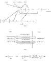
- FIG. 1 is a schematic diagram of a 5 th generation (5G) network architecture provided in the disclosure.
- a user equipment UE
- AN access network
- Uu access network
- AMF access and mobility management function
- the AMF is a mobility management function in a core network.
- a session management function SMF is a session management function in the core network.
- the AMF is further used for forwarding session management related messages between the UE and the SMF.
- a policy control function is a policy control function in the core network and is used for specifying policies related to mobility management, session management, charging, etc. of the UE.
- a user plane function is a user plane function in the core network. The UPF performs data transmission with an external network through N6 interface. The UPF is further used for data transmission with the AN through N3 interface.
- a data network (DN) in FIG. 1 represents a data network. The DN may be the external network. In some cases, the external network may also be other names such as external data network, target network, target data network, etc.
- the UE After accessing the 5G network through the Uu interface, under control of the SMF, the UE establishes a protocol data unit (PDU) session in order for data transmission.
- PDU protocol data unit
- the SMF obtains a policy and charging control (PCC) rule from the PCF, and determines, according to the PCC rule, a quality of service (QoS) rule for the UE to perform data transmission.
- PCC policy and charging control
- QoS quality of service
- the SMF provides the determined QoS rule to the UE via the AMF
- a requirement on end-to-end data transmission delay of the service of the UE is 200ms (millisecond)
- a requirement on data transmission delay specified by the QoS rule received by the UE is 200ms. It is to be noted that, the requirement on data transmission delay specified by the QoS rule herein is a requirement on data transmission delay between the UE and the UPF.
- FIG. 2 is a schematic architectural diagram of PC5 link based communication provided in the disclosure.
- UE 1 and UE 2 both have proximity-based services (ProSe) capability, and PC5 unicast link direct communication can be established between UE 1 and UE 2 through a PC5 interface.
- ProSe proximity-based services
- Different service data flows have different QoS requirements, and transmission can be performed through different QoS flows.
- UE 1 and UE 2 each generate a PC5 QoS rule and a corresponding QoS parameter according to a QoS requirement of a service, thereby ensuring data transmission quality of the service in communication on a PC5 link.
- UE 1 and UE 2 when UE 1 and UE 2 exchange a video transmission service through ProSe direct communication, UE 1 and UE 2 each determine, according to an application layer identity (ID) obtained from an application layer, that a requirement on data transmission delay corresponding to the PC5 QoS rule is 200ms. It is to be noted that, the data transmission delay referred to herein is a requirement on data transmission delay of direct transmission between UE 1 and UE 2.
- ID application layer identity
- a UE such as UE 1
- the UE can act as a relay node.
- Another UE having ProSe capability such as UE 2
- a QoS rule between UE 1 and a UPF that is obtained by UE 1 in the above manner illustrated in FIG. 1 may fail to satisfy an end-to-end QoS requirement of a service which is initiated by UE 2 and as a result, it is hard to satisfy service requirements of a user.
- a PCF controls a transmission delay from UE 1 to the external network to be 200ms according to the service requirement, and a transmission delay on the PC5 interface determined by UE 2 and UE 1 according to the service requirement is also 200ms.
- an actual transmission delay of the service is a sum of the 200ms transmission delay from UE 2 to UE 1 and the 200ms transmission delay from UE 1 to the external network, that is, the actual transmission delay of the service is 400ms. In this case, it is hard to satisfy a service requirement of UE 2.
- Implementations of the disclosure provide a method for QoS control, to solve problems in the related art. Before introducing the method for QoS control provided in implementations, an implementation environment involved in implementations of the disclosure will be first introduced.
- GSM global system of mobile communication
- CDMA code division multiple access
- WCDMA wideband code division multiple access
- GPRS general packet radio service
- LTE long term evolution
- LTE frequency division duplex FDD
- LTE time division duplex TDD
- LTE-A advanced LTE
- NR new radio
- UMTS universal mobile telecommunication system
- WiMAX worldwide interoperability for microwave access
- WLAN wireless local area networks
- WiFi wireless fidelity
- next-generation communication system or other communication systems, etc.
- a conventional communication system supports a limited number of connections and therefore is easy to implement.
- a mobile communication system will not only support conventional communication but also support, for example, device to device (D2D) communication, machine to machine (M2M) communication, machine type communication (MTC), vehicle to vehicle (V2V) communication, a vehicle to everything (V2X) system, etc. Implementations of the disclosure can also be applied to these communication systems.
- D2D device to device
- M2M machine to machine
- MTC machine type communication
- V2V vehicle to vehicle
- V2X vehicle to everything
- FIG. 4 is an architectural diagram of a communication system to which the disclosure can be applied.
- the communication system 100 illustrated in FIG. 4 includes a network device 110, a first terminal device 120, and a second terminal device 130.
- the network device 110 may be a device that can communicate with the first terminal device 120 (or referred to as first communication terminal, first terminal, first UE, or other names). In some cases, the network device 110 may also communicate with the second terminal device 130 (or referred to as second communication terminal, second terminal, second UE, or other names). The network device 110 can provide a communication coverage for a specific geographical area and communicate with terminals in the coverage area.
- the network device 110 may be an evolutional Node B (eNB or eNodeB) in an LTE system, or may be a radio controller in a cloud radio access network (CRAN).
- eNB evolutional Node B
- CRAN cloud radio access network
- the network device may be a mobile switching center, a relay station, an access point, an in-vehicle device, a wearable device, a hub, a switch, a bridge, a router, a network-side device in a 5G network, or a network device in a future communication system, etc.
- the "terminal" used herein includes but is not limited to a device configured to communicate via a wired line, another data connection/network, a wireless interface, a device which is part of another terminal and configured to receive/transmit communication signals, and/or an Internet of things (IoT) device.
- the wired line may include, but are not limited to, a public switched telephone network (PSTN), a digital subscriber line (DSL), a digital cable, and a direct connection cable.
- Examples of the wireless interface may include, but are not limited to, a wireless interface for a cellular network, a WLAN, a digital television network (such as a digital video broadcasting-handheld (DVB-H) network), a satellite network, and an amplitude modulation-frequency modulation (AM-FM) broadcast transmitter.
- a terminal configured to communicate via a wireless interface may be called a "wireless communication terminal", a “wireless terminal”, or a "mobile terminal”.
- Examples of the mobile terminal include, but are not limited to, a satellite telephone or cellular telephone, a personal communication system (PCS) terminal integrated with functions of cellular radio telephone, data processing, fax, and/or data communication, a personal digital assistant (PDA) equipped with radio telephone, pager, Internet/Intranet access, web browsing, notebook, calendar, and/or global positioning system (GPS) receiver, a conventional laptop and/or a handheld receiver, or other electronic devices equipped with radio telephone transceiver.
- PCS personal communication system
- PDA personal digital assistant
- GPS global positioning system
- the terminal device may refer to an access terminal, a UE, a subscriber unit, a subscriber station, a mobile station, a remote station, a remote terminal, a mobile device, a user terminal, a terminal, a wireless communication device, a user agent, or a user device.
- the access terminal may be a cellular radio telephone, a cordless telephone, a session initiation protocol (SIP) telephone, a wireless local loop (WLL) station, a PDA, a handheld device with wireless communication functions, a computing device, other processing devices coupled with a wireless modem, an in-vehicle device, a wearable device, a terminal in a 5G network, a terminal in a future evolved public land mobile network (PLMN), etc.
- SIP session initiation protocol
- WLL wireless local loop
- PDA personal area network
- PLMN future evolved public land mobile network
- the first terminal device 120 and the second terminal device 130 can communicate with each other through D2D communication.
- the second terminal device 130 can communicate with the network device via the first terminal device 120, or the first terminal device 120 can communicate with the network device via the second terminal device 130. It can be understood that, the first terminal device and the second terminal device referred to herein are relative and do not limit an order of terminal devices.
- a 5G communication system or 5G network can also be referred to as an NR system or NR network.
- FIG. 4 exemplarily illustrates one network device and two terminal devices.
- the communication system 100 may also include multiple network devices, and there can be other numbers of terminal devices in a coverage area of each of the network devices. Implementations of the disclosure are not limited in this regard.
- the communication system 100 may further include other network entities such as a network controller, a mobile management entity, a PCF, an SMF, or the like, and implementations of the disclosure are not limited in this regard.
- network entities such as a network controller, a mobile management entity, a PCF, an SMF, or the like, and implementations of the disclosure are not limited in this regard.
- a device with communication functions in a network/system can be referred to as a "communication device".
- the communication device may include the network device 110, the first terminal device 120, and the second terminal device 130 that have communication functions.
- the network device 110 and the terminal devices can be the devices described above and will not be repeated herein.
- the communication device may further include other devices such as a network controller, a mobile management entity, or other network entities in the communication system 100, and implementations of the disclosure are not limited in this regard.
- the following will describe in detail a method for QoS control provided in implementations of the disclosure.
- the method for QoS control provided in the disclosure includes at least some of the following.
- FIG. 5 is a flowchart of a method for QoS control provided in an implementation of the disclosure. As illustrated in FIG. 5 , the method in this implementation includes the following.
- a second terminal device provides (such as transmits) first information to a first terminal device.
- the first terminal device receives the first information provided by the second terminal device.
- the first information includes an end-to-end QoS requirement of a service which is initiated by the second terminal device and to be communicated to an external network via the first terminal device.
- the first terminal device is capable of communication with the external network and direct communication with the second terminal device.
- the second terminal device is capable of direct communication with the first terminal device.
- the first terminal device can act as an intermediate node used for communication between the second terminal device and the external network, that is, the second terminal device can communicate with the external network via the first terminal device.
- the first information further includes an ID of the service which is initiated by the second terminal device and/or an ID of the second terminal device.
- the first terminal device obtains first QoS information and second QoS information.
- the first QoS information is QoS information of communication between the first terminal device and the second terminal device.
- the second QoS information is QoS information of communication between the first terminal device and the external network. The end-to-end QoS requirement is satisfied by the first QoS information and the second QoS information obtained by the first terminal device.
- the first QoS information may include a QoS parameter.
- the QoS parameter includes, but is not limited to, one or more of a transmission delay, a bit error rate, a bandwidth, etc.
- the first QoS information may also be other names such as first QoS rule, first QoS parameter, first parameter, etc. Implementations of the disclosure are not limited in this regard.
- the second QoS information may include a QoS parameter.
- the QoS parameter includes, but is not limited to, one or more of a transmission delay, a bit error rate, a bandwidth, etc.
- the first QoS information may also be other names such as first QoS rule, first QoS parameter, first parameter, etc. Implementations of the disclosure are not limited in this regard.
- the first terminal device may obtain the first QoS information and the second QoS information in the following manners.
- the first terminal device can provide a network device the end-to-end QoS requirement of the service which is initiated by the second terminal device, and the network device configures the first QoS information and the second QoS information respectively according to the end-to-end QoS requirement. If the first information includes the ID of the service which is initiated by the second terminal device and/or the ID of the second terminal device, the first terminal device can further provide the ID of the service and/or the ID of the second terminal device to the network device, such that the network device configures the first QoS information and the second QoS information according to the end-to-end QoS requirement as well as the ID of the service and/or the ID of the second terminal device.
- the first terminal device requests a network device to configure the second QoS information. Then the first terminal device can obtain the first QoS information according to the end-to-end QoS requirement and the second QoS information configured by the network device. If the first information includes the ID of the service which is initiated by the second terminal device and/or the ID of the second terminal device, the first terminal device can further provide the ID of the service and/or the ID of the second terminal device to the network device, such that the network device can consider influence on the service and the second terminal device when configuring the second QoS information.
- the first terminal device determines a first QoS requirement and a second QoS requirement respectively according to the end-to-end QoS requirement of the service which is initiated by the second terminal device.
- the first QoS requirement referred to herein is a QoS requirement of communication between the first terminal device and the second terminal device determined by the first terminal device according to the end-to-end QoS requirement.
- the second QoS requirement is a QoS requirement of communication between the first terminal device and the external network determined by the first terminal device according to the end-to-end QoS requirement.
- the first terminal device provides the first QoS requirement and the second QoS requirement to a network device and requests authorization from the network device.
- the first terminal device obtains the first QoS information and the second QoS information according to authorization information of the network device.
- the manner in which the first terminal device obtains the first QoS information and the second QoS information is however not limited to the manners described above.
- the first terminal device first receives the first information provided by the second terminal device, where the first information includes the end-to-end QoS requirement of the service which is initiated by the second terminal device and to be communicated to the external network via the first terminal device.
- the first terminal device obtains the first QoS information of communication between the first terminal device and the second terminal device and the second QoS information of communication between the first terminal device and the external network, where the end-to-end QoS requirement of the service is satisfied by the first QoS information and the second QoS information.
- the method in this implementation it is possible to configure for the first terminal device the second QoS information that satisfies the end-to-end QoS requirement of the service, thereby ensuring a QoS of the service which is initiated by the second terminal device.
- the method may further include the following after S102.
- the first terminal device provides the first QoS information to the second terminal device. Accordingly, the second terminal device receives the first QoS information from the first terminal device.
- the first terminal device provides the first QoS information to the second terminal device, and it is possible to configure for the second terminal device the first QoS information that satisfies the end-to-end QoS requirement of the service, thereby ensuring a QoS of the service which is initiated by the second terminal device.
- the first terminal device can obtain the first QoS information and the second QoS information in various manners, which will be elaborated below with reference to specific implementations.
- FIG. 6 is a flowchart of a method for QoS control provided in another implementation of the disclosure. As illustrated in FIG. 6 , the method in this implementation includes the following.
- the second terminal device provides the first information to the first terminal device.
- S201 in this implementation is similar to S101 in the implementation illustrated in FIG. 5 .
- the first terminal device provides second information to a first network device.
- the first network device receives the second information from the first terminal device.
- the second information is used for requesting to determine the first QoS information and the second QoS information.
- the second information may include the end-to-end QoS requirement of the service which is initiated by the second terminal device and to be communicated to the external network via the first terminal device.
- the second information further includes the ID of the service and/or the ID of the second terminal device.
- the ID of the service is used for determining the first QoS information and the second QoS information
- the ID of the second terminal device is used for determining the first QoS information and the second QoS information.
- the first network device obtains the first QoS information and the second QoS information according to the second information.
- the first network device can obtain the first QoS information and the second QoS information according to the end-to-end QoS requirement and a pre-configured QoS control policy. If the second information further includes the ID of the service and/or the ID of the second terminal device, the first network device can determine the first QoS information and the second QoS information according to the end-to-end QoS requirement, the pre-configured QoS control policy, and the ID of the service and/or the ID of the second terminal device.
- the second network device can determine the first QoS information and the second QoS information according to the end-to-end QoS requirement and a pre-configured QoS control policy, and provide the first QoS information and the second QoS information determined to the first network device.
- the first network device can also provide the ID of the service and/or the ID of the second terminal device to the second network device, such that the second network device determines the first QoS information and the second QoS information according to the end-to-end QoS requirement, the pre-configured QoS control policy, and the ID of the service and/or the ID of the second terminal device.
- S2031 ⁇ S2033 are performed after S202.
- the first network device provides sixth information to the second network device. Accordingly, the second network device receives the sixth information from the first network device.
- the sixth information provided by the first network device to the second network device is used for requesting to determine the first QoS information and the second QoS information.
- the sixth information may include the end-to-end QoS requirement of the service.
- the sixth information further includes the ID of the service and/or the ID of the second terminal device.
- the second network device determines the first QoS information and the second QoS information according to the end-to-end QoS requirement.
- the second network device determines the first QoS information and the second QoS information according to the end-to-end QoS requirement of the service and a pre-configured QoS control policy. If the sixth information further includes an ID of the service and/or an ID of the second terminal device, the second network device determines the first QoS information and the second QoS information according to the end-to-end QoS requirement, the pre-configured QoS control policy, and the ID of the service and/or the ID of the second terminal device.
- the second network device provides seventh information to the first network device. Accordingly, the first network device receives the seventh information provided by the second network device and obtains the first QoS information and the second QoS information from the seventh information.
- the seventh information may include the first QoS information and the second QoS information, or the seventh information may include indication information of the first QoS information and indication information of the second QoS information.
- the pre-configured QoS control policy involved in implementations may be determined by an operator according to factors such as service type, transmission resource, user priority, etc. There is no limitation on the pre-configured QoS control policy in implementations of the disclosure. In other words, there is no limitation on the manner in which the first network device or the second network device determines the first QoS information and the second QoS information in implementations of the disclosure.
- the first network device provides third information to the first terminal device. Accordingly, the first terminal device receives the third information from the first network device.
- the third information includes the first QoS information and the second QoS information, or the third information includes indication information of the first QoS information and indication information of the second QoS information.
- the first terminal device obtains the first QoS information and the second QoS information according to the third information.
- the first terminal device first receives the first information provided by the second terminal device, where the first information includes the end-to-end QoS requirement of the service which is initiated by the second terminal device and to be communicated to the external network via the first terminal device.
- the first terminal device provides the first network device the second information including the end-to-end QoS requirement.
- the first network device obtains and provides the first QoS information of communication between the first terminal device and the second terminal device and the second QoS information of communication between the first terminal device and the external network.
- the first terminal device obtains the first QoS information and the second QoS information, where the end-to-end QoS requirement of the service is satisfied by the first QoS information and the second QoS information.
- the method in this implementation it is possible to configure for the first terminal device the second QoS information that satisfies the end-to-end QoS requirement of the service, thereby ensuring a QoS of the service which is initiated by the second terminal device.
- the method may further include the following after S205.
- the first terminal device provides the first QoS information to the second terminal device.
- the first terminal device provides the first QoS information to the second terminal device, and it is possible to configure for the second terminal device the first QoS information that satisfies the end-to-end QoS requirement of the service, thereby ensuring a QoS of the service which is initiated by the second terminal device.
- FIG. 7 is a flowchart of a method for QoS control provided in another implementation of the disclosure. As illustrated in FIG. 7 , the method in this implementation includes the following.
- the second terminal device provides the first information to the first terminal device.
- S301 in this implementation is similar to S101 in the implementation illustrated in FIG. 5 .
- the first terminal device determines the first QoS requirement and the second QoS requirement according to the first information.
- the first QoS requirement is a QoS requirement of communication between the first terminal device and the second terminal device determined by the first terminal device according to the end-to-end QoS requirement.
- the second QoS requirement is a QoS requirement of communication between the first terminal device and the external network determined by the first terminal device according to the end-to-end QoS requirement. It is to be noted that, the end-to-end QoS requirement is satisfied by the first QoS requirement and the second QoS requirement.
- the first terminal device provides second information to a first network device.
- the first network device receives the second information from the first terminal device.
- the second information is used for requesting to determine the first QoS information and the second QoS information.
- the second information may include the first QoS requirement and the second QoS requirement that are determined by the first terminal device according to the end-to-end QoS requirement.
- the first network device obtains the first QoS information and the second QoS information according to the second information.
- the first network device can obtain the first QoS information and the second QoS information according to the first QoS requirement and the second QoS requirement as well as a pre-configured QoS control policy. If the first network device determines, according to the first QoS requirement and the second QoS requirement as well as the pre-configured QoS control policy, that the first QoS requirement and the second QoS requirement can be authorized, the first QoS information obtained is the first QoS requirement, and the second QoS information obtained is the second QoS requirement.
- the second network device can determine the first QoS information and the second QoS information according to the first QoS requirement and the second QoS requirement as well as a pre-configured QoS control policy, and provide the first QoS information and the second QoS information determined to the first network device.
- S3041 ⁇ S3043 are performed after S303.
- the first network device provides sixth information to the second network device. Accordingly, the second network device receives the sixth information from the first network device.
- the sixth information provided by the first network device to the second network device is used for requesting to determine the first QoS information and the second QoS information.
- the sixth information may include the first QoS requirement and the second QoS requirement.
- the second network device determines the first QoS information and the second QoS information according to the first QoS requirement and the second QoS requirement.
- the second network device determines the first QoS information and the second QoS information according to the first QoS requirement and the second QoS requirement as well as the pre-configured QoS control policy.
- the second network device provides seventh information to the first network device. Accordingly, the first network device receives the seventh information provided by the second network device, and obtains the first QoS information and the second QoS information from the seventh information.
- the seventh information may include the first QoS information and the second QoS information, or the seventh information may include indication information of the first QoS information and indication information of the second QoS information.
- the pre-configured QoS control policy involved in implementations may be determined by an operator according to factors such as service type, transmission resource, user priority, etc. There is no limitation on the pre-configured QoS control policy in implementations of the disclosure. In other words, there is no limitation on the manner in which the first network device or the second network device determines the first QoS information and the second QoS information in implementations of the disclosure.
- the first network device provides third information to the first terminal device. Accordingly, the first terminal device receives third information from the first network device.
- the third information includes the first QoS information and the second QoS information, or the third information includes indication information of the first QoS information and indication information of the second QoS information.
- the first terminal device obtains the first QoS information and the second QoS information according to the third information.
- the first terminal device first receives the first information provided by the second terminal device, where the first information includes the end-to-end QoS requirement of the service which is initiated by the second terminal device and to be communicated to the external network via the first terminal device.
- the first terminal device provides the first network device the sixth information including the first QoS requirement and the second QoS requirement.
- the first network device obtains and provides the first QoS information of communication between the first terminal device and the second terminal device and the second QoS information of communication between the first terminal device and the external network.
- the first terminal device obtains the first QoS information and the second QoS information, where the end-to-end QoS requirement of the service is satisfied by the first QoS information and the second QoS information.
- the method in this implementation it is possible to configure for the first terminal device the second QoS information that satisfies the end-to-end QoS requirement of the service, thereby ensuring a QoS of the service which is initiated by the second terminal device.
- the method may further include the following after S306.
- the first terminal device provides the first QoS information to the second terminal device.
- the first terminal device provides the first QoS information to the second terminal device, and it is possible to configure for the second terminal device the first QoS information that satisfies the end-to-end QoS requirement of the service, thereby ensuring a QoS of the service which is initiated by the second terminal device.
- FIG. 8 is a flowchart of a method for QoS control provided in another implementation of the disclosure. As illustrated in FIG. 8 , the method in this implementation includes the following.
- the second terminal device provides the first information to the first terminal device.
- S401 in this implementation is similar to S101 in the implementation illustrated in FIG. 5 .
- the first terminal device provides fourth information to a first network device according to the end-to-end QoS requirement.
- the first network device receives the second information from the first terminal device.
- the fourth information is used for requesting to determine the second QoS information.
- the second information may include domain information of the external network, an ID of the external network, or slice information of the external network, etc.
- the first network device obtains the second QoS information according to the fourth information.
- the first network device can obtain the second QoS information according to the fourth information and a pre-configured QoS control policy.
- the second network device can determine the second QoS information according to the fourth information and a pre-configured QoS control policy, and provide the second QoS information determined to the first network device.
- the first network device provides sixth information to the second network device. Accordingly, the second network device receives the sixth information from first network device.
- the sixth information is used for requesting to determine the second QoS information.
- the sixth information may include information contained in second information.
- the second network device determines the second QoS information according to the sixth information.
- the second network device determines the second QoS information according to the second information and a pre-configured QoS control policy.
- the second network device provides seventh information to the first network device. Accordingly, the first network device receives the seventh information provided by the second network device and obtains the second QoS information from the seventh information.
- the seventh information may include the second QoS information, or the seventh information may include indication information of the second QoS information.
- the pre-configured QoS control policy involved in implementations may be determined by an operator according to factors such as service type, transmission resource, user priority, etc. There is no limitation on the pre-configured QoS control policy in implementations of the disclosure. In other words, there is no limitation on the manner in which the first network device or the second network device determines the second QoS information in implementations of the disclosure.
- the first network device provides fifth information to the first terminal device. Accordingly, the first terminal device receives the third information from the first network device.
- the fifth information includes the second QoS information, or the fifth information includes indication information of the second QoS information.
- the first terminal device obtains the second QoS information from the fifth information.
- the first terminal device obtains the first QoS information according to the end-to-end QoS requirement and the second QoS information.
- the first terminal device first receives the first information provided by the second terminal device, where the first information includes the end-to-end QoS requirement of the service which is initiated by the second terminal device and to be communicated to the external network via the first terminal device.
- the first terminal device provides the first network device the fourth information used for determining the second QoS information.
- the first network device obtains and provides the second QoS information of communication between the first terminal device and the external network according to the fourth information.
- the first terminal device obtains the first QoS information according to the end-to-end QoS requirement and the second QoS information, where the end-to-end QoS requirement of the service is satisfied by the first QoS information and the second QoS information.
- the method in this implementation it is possible to configure for the first terminal device the second QoS information that satisfies the end-to-end QoS requirement of the service, thereby ensuring a QoS of the service which is initiated by the second terminal device.
- the method may further include the following after S406.
- the first terminal device provides the first QoS information to the second terminal device.
- the first terminal device provides the first QoS information to the second terminal device, and it is possible to configure for the second terminal device the first QoS information that satisfies the end-to-end QoS requirement of the service, thereby ensuring a QoS of the service which is initiated by the second terminal device.
- the method for QoS control provided in the disclosure is described in detail in the case where the first terminal device is a relay UE, the second terminal device is a remote UE, the first network device is an SMF, and the second network device is a PCF.
- the relay UE and the remote UE may communicate with each other through a PC5 interface, and the remote UE may also communicate with the external network via the relay UE.
- FIG. 3 For details of this scenario, reference can be made to elaborations of FIG. 3 .
- FIG. 9 is a flowchart of a method for QoS control provided in another implementation of the disclosure. As illustrated in FIG. 9 , the method in this implementation includes the following.
- a remote UE provides first information to a relay UE.
- the first information includes an end-to-end QoS requirement.
- the remote UE first determines the end-to-end QoS requirement once triggered by an application. Then the remote UE provides a PC5-connection establishment or modification request to the relay UE, where the PC5-connection establishment or modification request may include an end-to-end QoS requirement of a service which is initiated by the remote UE and to be communicated to an external network via the relay UE.
- the end-to-end QoS requirement includes, but is not limited to, parameters such as transmission delay, bit error rate, bandwidth, etc.
- the end-to-end QoS requirement may include, for example, a PC5 5G QoS identifier (5QI) (PQI) value, where the PQI value indicates an end-to-end QoS requirement from the remote UE to the external network.
- PQI PC5 5G QoS identifier
- the end-to-end QoS requirement may also be indicated by information other than the PQI value.
- Table 1 PQI Priority Delay Bit error rate 95 2 200ms 10 -2
- the PC5-connection establishment or modification request may further include an ID of the service and/or an ID of the remote UE.
- the relay UE receives the first information provided by the remote UE.
- the relay UE provides a PDU-session establishment or modification request to an SMF.
- the PDU-session establishment or modification request includes the end-to-end QoS requirement.
- the SMF receives the PDU-session establishment or modification request from the relay UE.
- the PDU-session establishment or modification request provided by the relay UE is passed to the SMF through an AN and an AMF
- the SMF determines a QoS rule and a PC5 QoS parameter according to the end-to-end QoS requirement.
- the QoS rule is a QoS rule of a PDU session executed by the relay UE.
- the PC5 QoS parameter is a QoS parameter of a PC5 interface used for communication between the remote UE and the relay UE.
- S5031 and S5032 can be performed after S502.
- the SMF provides a session management (SM) policy association establishment or modification request to the PCF.
- SM session management
- the SM policy association establishment or modification request includes the end-to-end QoS requirement.
- the PCF receives the SM policy association establishment or modification request and obtains the end-to-end QoS requirement.
- the PCF provides an SM policy association establishment or modification response to the SMF.
- the SM policy association establishment or modification response includes a PCC rule and the PC5 QoS parameter.
- the PCF may generate the PCC rule and the PC5 QoS parameter according to the end-to-end QoS requirement and a pre-configured QoS control policy. Then the PCC rule and the PC5 QoS parameter generated are provided to the SMF through the SM policy association establishment or modification response.
- the PCC rule can be used for determining the QoS rule, where the QoS rule is a QoS rule of a PDU session executed by the relay UE.
- a 5QI mapping table shown in table 2 below and a PQI mapping table shown in table 3 are pre-configured or standardized in a network.
- PQI is used for a PC5 interface between the remote UE and the relay UE.
- 5QI is used between the relay UE and a UPF, or the 5QI may be comprehended as being used between the relay UE and the external network.
- PDB represents a delay.
- Table 2 5QI Priority Delay Bit error rate 66 20 100ms 10 -2
- Table 3 PQI Priority Delay Bit error rate 58 4 100ms 10 -2
- the PC5 QoS parameter and the PCC rule may be separately provided, or the PC5 QoS parameter may be carried in the PCC rule for transmission, and implementations of the disclosure are not limited in this regard.
- the SMF provides a PDU-session establishment or modification response to the relay UE.
- the PDU-session establishment or modification response includes the QoS rule and the PC5 QoS parameter.
- the PC5 QoS parameter is a QoS parameter of a PC5 interface used for communication between the remote UE and the relay UE.
- the relay UE receives the PDU-session establishment or modification response from the SMF, and obtains the QoS rule and the PC5 QoS parameter included in the PDU-session establishment or modification response.
- the PDU-session establishment or modification response provided by the SMF is passed to the relay UE through the AN and the AMF
- the relay UE can control quality of data transmission between the relay UE and the external network according to the received QoS rule, that is, the relay UE can control quality of data transmission between the relay UE and the UPF according to the received QoS rule.
- the relay UE provides the PC5 QoS parameter to the remote UE.
- the remote UE receives the PC5 QoS parameter provided by the relay UE. Then the remote UE can control quality of data transmission between the remote UE and the relay UE according to the received PC5 QoS parameter.
- the SMF can further provide the QoS rule to the AN, such that the AN determines, according to a communication resource condition, whether the QoS rule is satisfied. If the AN determines that a communication resource fails to satisfy the QoS rule, the AN can provide indication information to the SMF, to indicate that the communication resource fails to satisfy the QoS rule.
- the SMF can redetermine the QoS rule and the PC5 QoS parameter according to the end-to-end QoS requirement, or the SMF requests the PCF to redetermine the QoS rule and the PC5 QoS parameter according to the end-to-end QoS requirement.
- the manner of redetermining the QoS rule and the PC5 QoS parameter above is similar to that in S503 and that in S5031 and S5032 and will not be elaborated again herein.
- FIG. 10 is a flowchart of a method for QoS control provided in another implementation of the disclosure. As illustrated in FIG. 10 , the method in this implementation includes the following.
- a remote UE provides first information to a relay UE.
- the first information includes an end-to-end QoS requirement.
- the remote UE first determines the end-to-end QoS requirement once triggered by an application. Then the remote UE provides a PC5-connection establishment or modification request to the relay UE, where the PC5-connection establishment or modification request may include an end-to-end QoS requirement of a service which is initiated by the remote UE and to be communicated to an external network via the relay UE.
- the end-to-end QoS requirement includes, but is not limited to, parameters such as transmission delay, bit error rate, bandwidth, etc.
- the end-to-end QoS requirement may include, for example, a PQI value, where the PQI value indicates an end-to-end QoS requirement from the remote UE to the external network. It is to be noted that, the end-to-end QoS requirement may also be indicated by information other than the PQI value.
- the PC5-connection establishment or modification request may further include an ID of the service and/or an ID of the remote UE.
- the relay UE receives the first information provided by the remote UE.
- the relay UE provides a PDU-session establishment or modification request to an SMF.
- the PDU-session establishment or modification request may include one or more of an ID of the external network, a domain of the external network, slice information of the external network, etc.
- the PDU-session establishment or modification request provided by the relay UE to the SMF is used for requesting to determine a QoS rule of the PDU session.
- the PDU-session establishment or modification request provided by the relay UE is passed to the SMF through an AN and an AMF
- the PDU-session establishment or modification request may further include an ID of the service which is initiated by the remote UE and/or an ID of the remote UE.
- the SMF determines a QoS rule.
- the QoS rule is a QoS rule of a PDU session executed by the relay UE.
- the SMF can determine the QoS rule according to a pre-configured QoS control policy.
- the SMF can determine the QoS rule according to a pre-configured QoS control policy and the ID of the service and/or the ID of the remote UE.
- S6031 and S6032 can be performed after S602.
- the SMF provides an SM policy association establishment or modification request to the PCF.
- the SM policy association establishment or modification request may include the ID of the service and/or the ID of the second terminal device.
- the PCF provides an SM policy association establishment or modification response to the SMF.
- the SM policy association establishment or modification response includes a PCC rule.
- the PCF may determine the QoS rule according to the pre-configured QoS control policy, or the PCF may determine the QoS rule according to the pre-configured QoS control policy and the ID of the service and/or the ID of the remote UE. Then the PCF provides a generated PCC rule to the SMF through the SM policy association establishment or modification response.
- the PCC rule can be used for determining a QoS rule, where the QoS rule is a QoS rule of a PDU session executed by the relay UE.
- the SMF provides a PDU-session establishment or modification response to a relay UE.
- the PDU-session establishment or modification response includes the QoS rule.
- the relay UE receives the PDU-session establishment or modification response from the SMF, and obtains the QoS rule included in the PDU-session establishment or modification response.
- the PDU-session establishment or modification response provided by the SMF is passed to the relay UE through the AN and the AMF
- the relay UE can control quality of data transmission between the relay UE and the external network according to the received QoS rule, that is, the relay UE can control quality of data transmission between the relay UE and a UPF according to the received QoS rule.
- the relay UE determines a PC5 QoS parameter according to the QoS rule and the end-to-end QoS requirement.
- the end-to-end QoS requirement is satisfied by the PC5 QoS parameter determined by the relay UE and the QoS rule provided by the SMF
- the end-to-end QoS requirement of the service which is initiated by the remote UE includes a transmission delay requirement, where the transmission delay requirement is 200ms.
- the QoS rule provided by the SMF indicates that a transmission delay from the relay UE to the external network is 100ms.
- the relay UE can determine that a transmission delay between the relay UE and the remote UE is 100ms.
- the relay UE provides the PC5 QoS parameter to the remote UE.
- the remote UE receives the PC5 QoS parameter provided by the relay UE. Then the remote UE can control quality of data transmission between the remote UE and the relay UE according to the received PC5 QoS parameter. Similar to the above implementations, the relay UE can provide a PQI value to the remote UE to indicate a QoS parameter of a PC5 interface, or the QoS parameter of the PC5 interface can be directly provided.
- the SMF can further provide the QoS rule to the AN, such that the AN determines, according to a communication resource condition, whether the QoS rule is satisfied. If the AN determines that a communication resource fails to satisfy the QoS rule, the AN can provide indication information to the SMF, to indicate that the communication resource fails to satisfy the QoS rule.
- the SMF can redetermine the QoS rule and the PC5 QoS parameter according to the end-to-end QoS requirement, or the SMF requests the PCF to redetermine the QoS rule and the PC5 QoS parameter according to the end-to-end QoS requirement.
- the manner of redetermining the QoS rule and the PC5 QoS parameter above is similar to that in S503 and that in S5031 and S5032 and will not be elaborated again herein.
- FIG. 11 is a flowchart of a method for QoS control provided in another implementation of the disclosure. As illustrated in FIG. 11 , the method in this implementation includes the following.
- a remote UE provides first information to a relay UE.
- the first information includes an end-to-end QoS requirement.
- the remote UE first determines the end-to-end QoS requirement once triggered by an application. Then the remote UE provides a PC5-connection establishment or modification request to the relay UE, where the PC5-connection establishment or modification request may include an end-to-end QoS requirement of a service which is initiated by the remote UE and to be communicated to an external network via the relay UE.
- the end-to-end QoS requirement includes, but is not limited to, parameters such as transmission delay, bit error rate, bandwidth, etc.
- the end-to-end QoS requirement may include, for example, a PQI value, where the PQI value indicates an end-to-end QoS requirement from the remote UE to the external network. It is to be noted that, the end-to-end QoS requirement may also be indicated by information other than the PQI value.
- the relay UE receives the first information provided by the remote UE.
- the relay UE determines a PC5 QoS requirement and a QoS requirement between the relay UE and the external network according to the end-to-end QoS requirement.
- the PC5 QoS requirement referred to herein is a QoS requirement between the remote UE and the relay UE.
- the relay UE provides a PDU-session establishment or modification request to an SMF.
- the PDU-session establishment or modification request may include the PC5 QoS requirement and the QoS requirement between the relay UE and the external network determined in S702.
- the PDU-session establishment or modification request provided by the relay UE to the SMF is used for requesting the SMF to authorize the PC5 QoS requirement and the QoS requirement between the relay UE and the external network obtained in S702.
- the PDU-session establishment or modification request provided by the relay UE is passed to the SMF through an AN and an AMF
- the SMF determines a PC5 QoS parameter and a QoS rule.
- the SMF may determine the PC5 QoS parameter and the QoS rule according to a pre-configured QoS control policy.
- the QoS rule is a QoS rule of a PDU session executed by the relay UE.
- the PC5 QoS parameter is a QoS parameter of a PC5 interface used for communication between the remote UE and the relay UE.
- S7041 and S7042 can be performed after S702.
- the SMF provides an SM policy association establishment or modification request to the PCF.
- the SM policy association establishment or modification request may include the PC5 QoS requirement and the QoS requirement between the relay UE and the external network.
- the PCF provides an SM policy association establishment or modification response to the SMF.
- the SM policy association establishment or modification response includes a PCC rule and a PC5 QoS parameter.
- the PCF can determine the PCC rule and the PC5 QoS parameter according to the pre-configured QoS control policy.
- the PCC rule can be used for determining a QoS rule, where the QoS rule is a QoS rule of a PDU session executed by the relay UE.
- the SMF provides a PDU-session establishment or modification response to the relay UE.
- the PDU-session establishment or modification response includes the PC5 QoS parameter and the QoS rule.
- the relay UE receives the PDU-session establishment or modification response from the SMF, and obtains the PC5 QoS parameter and the QoS rule included in the PDU-session establishment or modification response.
- the PDU-session establishment or modification response provided by the SMF is passed to the relay UE through the AN and the AMF
- the relay UE can control quality of data transmission between the relay UE and the external network according to the received QoS rule, that is, the relay UE can control quality of data transmission between the relay UE and a UPF according to the received QoS rule.
- the relay UE provides the PC5 QoS parameter to the remote UE.
- the remote UE receives the PC5 QoS parameter provided by the relay UE. Then the remote UE can control quality of data transmission between the remote UE and the relay UE according to the received PC5 QoS parameter.
- the SMF can further provide the QoS rule to the AN, such that the AN determines, according to a communication resource condition, whether the QoS rule is satisfied. If the AN determines that a communication resource fails to satisfy the QoS rule, the AN can provide indication information to the SMF, to indicate that the communication resource fails to satisfy the QoS rule.
- the SMF can redetermine the QoS rule and the PC5 QoS parameter according to the end-to-end QoS requirement, or the SMF requests the PCF to redetermine the QoS rule and the PC5 QoS parameter according to the end-to-end QoS requirement.
- the manner of redetermining the QoS rule and the PC5 QoS parameter above is similar to that in S503 and that in S5031 and S5032 and thus will not be elaborated again herein.
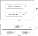
- FIG. 12 is a schematic structural diagram of a terminal device provided in an implementation of the disclosure.
- the terminal device 200 provided in this implementation of the disclosure may be the first terminal device in the foregoing implementations or part of the first terminal device.
- the terminal device 200 in this implementation includes a transceiver module 201 and a processing module 202.
- the transceiver module 201 is configured to receive first information from a second terminal device, where the first information includes an end-to-end QoS requirement of a service which is initiated by the second terminal device and to be communicated to an external network via the first terminal device.
- the processing module 202 is configured to obtain first QoS information and second QoS information.
- the first QoS information is QoS information of communication between the first terminal device and the second terminal device
- the second QoS information is QoS information of communication between the first terminal device and the external network
- the end-to-end QoS requirement is satisfied by the first QoS information and the second QoS information.
- the terminal device provided in this implementation may be configured to implement technical solutions at the first-terminal-device side in any of the foregoing method implementations.
- the implementation principles and technical effects thereof are similar and will not be elaborated again herein.
- the transceiver module 201 is further configured to provide the first QoS information to the second terminal device.
- the first QoS information and the second QoS information are obtained by the processing module 202 according to third information provided by a first network device, and the third information indicates the first QoS information and the second QoS information.
- the third information includes the first QoS information and the second QoS information, or the third information includes indication information of the first QoS information and indication information of the second QoS information.
- the transceiver module 201 is further configured to provide second information to the first network device according to the end-to-end QoS requirement, where the second information is used for determining the first QoS information and the second QoS information.
- the second information includes the end-to-end QoS requirement.
- the second information includes a first QoS requirement and a second QoS requirement.
- the first QoS requirement is a QoS requirement of communication between the first terminal device and the second terminal device determined by the first terminal device according to the end-to-end QoS requirement
- the second QoS requirement is a QoS requirement of communication between the first terminal device and the external network determined by the first terminal device according to the end-to-end QoS requirement.
- the second information further includes an ID of the service and/or an ID of the second terminal device.
- the ID of the service is used for determining the first QoS information and the second QoS information
- the ID of the second terminal device is used for determining the first QoS information and the second QoS information.
- the first QoS information is determined by the processing module 202 according to the end-to-end QoS requirement and fifth information provided by a first network device, and the fifth information includes the second QoS information.
- the transceiver module 201 is further configured to provide fourth information to the first network device according to the end-to-end QoS requirement, where the fourth information is used for determining the second QoS information.
- the fourth information further includes an ID of the service and/or an ID of the second terminal device, and the ID of the service and/or the ID of the second terminal device is used for determining the second QoS information.
- the first information further includes an ID of the service and/or an ID of the second terminal device.
- the ID of the service is used for determining the first QoS information and the second QoS information
- the ID of the second terminal device is used for determining the first QoS information and the second QoS information.
- FIG. 13 is a schematic structural diagram of a terminal device provided in another implementation of the disclosure.
- the terminal device 300 provided in this implementation may be the second terminal device in the foregoing implementations or part of the second terminal device.
- the terminal device 300 in this implementation includes a transceiver module 301 and a processing module 302.
- the transceiver module 301 is configured to provide first information to a first terminal device, where the first information includes an end-to-end QoS requirement of a service which is initiated by the second terminal device and to be communicated to an external network via the first terminal device.
- the transceiver module 301 is further configured to receive first QoS information from the first terminal device.
- the processing module 302 is configured to obtain the first QoS information from information received.
- the first QoS information is QoS information of communication between the first terminal device and the second terminal device.
- the second terminal device provided in this implementation may be configured to implement technical solutions at the second-terminal-device side in any of the foregoing method implementations.
- the implementation principles and technical effects thereof are similar and will not be elaborated again herein.
- the first QoS information is obtained by the first terminal device according to third information provided by a first network device, where the third information indicates the first QoS information and second QoS information.
- the second QoS information is QoS information of communication between the first terminal device and the external network. The end-to-end QoS requirement is satisfied by the first QoS information and the second QoS information.
- the third information includes the first QoS information and the second QoS information, or the third information includes indication information of the first QoS information and indication information of the second QoS information.
- the first QoS information is determined by the first terminal device according to the end-to-end QoS requirement and fifth information provided by the first network device, where the fifth information includes the second QoS information.
- the first information further includes an ID of the service and/or an ID of the second terminal device.
- the ID of the service is used for determining the first QoS information and the second QoS information
- the ID of the second terminal device is used for determining the first QoS information and the second QoS information.
- FIG. 14 is a schematic structural diagram of a network device provided in an implementation of the disclosure.
- the network device 400 provided in this implementation may be the first network device in the foregoing implementations or part of the first network device.
- the network device 400 in this implementation includes a transceiver module 401 and a processing module 402.
- the transceiver module 401 is configured to receive information used for determining second QoS information and provided by a first terminal device according to an end-to-end QoS requirement, where the end-to-end QoS requirement is an end-to-end QoS requirement of a service which is initiated by a second terminal device and to be communicated to an external network via the first terminal device.
- the processing module 402 is configured to obtain the second QoS information according to the information used for determining the second QoS information, where the second QoS information is QoS information of communication between the first terminal device and the external network.
- the transceiver module 401 is further configured to provide information indicative of the second QoS information to the first terminal device.
- the network device provided in this implementation may be configured to implement technical solutions at the first-network-device side in any of the foregoing method implementations.
- the implementation principles and technical effects thereof are similar and will not be elaborated again herein.
- the information used for determining the second QoS information and provided by the first terminal device according to the end-to-end QoS requirement further includes an ID of the service and/or an ID of the second terminal device, where the ID of the service and/or the ID of the second terminal device is used for determining the second QoS information.
- the transceiver module 401 is further configured to provide the information used for determining the second QoS information to a second network device, and receive the information indicative of the second QoS information provided by the second network device.
- the processing module 402 is specifically configured to obtain the second QoS information from the received information indicative of the second QoS information.
- the information used for determining the second QoS information and provided by the first terminal device according to the end-to-end QoS requirement is further used for determining first QoS information, where the first QoS information is QoS information of communication between the first terminal device and the second terminal device, and the end-to-end QoS requirement is satisfied by the first QoS information and the second QoS information.
- information used for determining the first QoS information and the second QoS information and provided by the first terminal device according to the end-to-end QoS requirement includes the end-to-end QoS requirement.
- information used for determining the first QoS information and the second QoS information and provided by the first terminal device according to the end-to-end QoS requirement includes a first QoS requirement and a second QoS requirement.
- the first QoS requirement is a QoS requirement of communication between the first terminal device and the second terminal device determined by the first terminal device according to the end-to-end QoS requirement
- the second QoS requirement is a QoS requirement of communication between the first terminal device and the external network determined by the first terminal device according to the end-to-end QoS requirement.
- the processing module 402 is specifically configured to obtain the first QoS information from the second network device.
- the transceiver module 401 is further configured to provide information indicative of the first QoS information to the first terminal device.
- the information used for determining the first QoS information and the second QoS information and provided by the first terminal device according to the end-to-end QoS requirement further includes an ID of the service and/or an ID of the second terminal device.
- the ID of the service is used for determining the first QoS information and the second QoS information
- the ID of the second terminal device is used for determining the first QoS information and the second QoS information.
- the transceiver module 401 is specifically configured to provide information used for determining the first QoS information to the second network device, and receive information indicative of the first QoS information provided by the second network device.
- the processing module 402 is specifically configured to obtain the first QoS information from the received information indicative of the first QoS information.
- the information used for determining the first QoS information and provided by the transceiver module 401 to the second network device includes the end-to-end QoS requirement.
- the information used for determining the first QoS information and provided by the transceiver module 401 to the second network device further includes an ID of the service and/or an ID of the second terminal device.
- the ID of the service is used for determining the first QoS information and the second QoS information
- the ID of the second terminal device is used for determining the first QoS information and the second QoS information.
- FIG. 15 is a schematic structural diagram of an electronic device provided in another implementation of the disclosure.
- the electronic device 500 includes a processor 511, a memory 512, and an interface 513 configured for communication with a network device.
- the memory 512 is configured to store computer executable instructions.
- the processor 511 is configured to execute the computer executable instructions stored in the memory 512, to perform the technical solutions at the first-terminal-device side, or at second-terminal-device side, or at the first-network-device side, or at the second-network-device side in any of the foregoing method implementations.
- FIG. 15 is a simple design of the electronic device. There is no limitation on the number of processors and memories of the electronic device in implementations of the disclosure. FIG. 15 only takes the number of 1 as an example for illustration.
- the memory, the processor, and the interface may be coupled via a bus 514.
- the memory may be integrated into the processor.
- Implementations of the disclosure further provide a computer-readable storage medium.
- the computer-readable storage medium is configured to store computer executable instructions which, when executed by a processor, are operable with the processor to perform the technical solutions at the first-terminal-device side, or at the second-terminal-device side, or at the first-network-device side, or at the second-network-device side in any of the foregoing method implementations.
- Implementations of the disclosure further provide a program.
- the program when executed by a processor, is operable with the processor to perform the technical solutions at the first-terminal-device side, or at the second-terminal-device side, or at the first-network-device side, or at the second-network-device side in any of the foregoing method implementations.
- the processor described above may be a chip.
- Implementations of the disclosure further provide a computer program product.
- the computer program product includes program instructions.
- the program instructions implement the technical solutions at the first-terminal-device side, or at the second-terminal-device side, or at the first-network-device side, or at the second-network-device side in any of the foregoing method implementations.
- Implementations of the disclosure further provide a chip.
- the chip includes a processing module and a communication interface.
- the processing module can be configured to perform the technical solutions at the first-terminal-device side, or at the second-terminal-device side, or at the first-network-device side, or at the second-network-device side in any of the foregoing method implementations.
- the chip further includes a storage module (such as memory).
- the storage module is configured to store instructions.
- the processing module is configured to execute the instructions stored in the storage module, and execution of the instructions stored in the storage module makes the processing module perform the technical solutions at the first-terminal-device side, or at the second-terminal-device side, or at the first-network-device side, or at the second-network-device side in any of the foregoing method implementations.
- the devices and methods disclosed may also be implemented in other manners.
- the device implementations described above are merely illustrative, e.g., the division of modules is only a division of logical functions, and other manners of division may be available in practice, e.g., multiple modules may be combined or may be integrated into another system, or some features may be ignored or skipped.
- the coupling or direct coupling or communication connection as illustrated or discussed may be an indirect coupling or communication connection through some interface or module, and may be electrical, mechanical, or otherwise.
- the processor may be a central processing unit (CPU), or may be other general-purpose processors, digital signal processors (DSP), application specific integrated circuits (ASIC), etc.
- the general purpose processor may be a microprocessor, or the processor may also be any conventional processor or the like.
- the steps of the method disclosed in the disclosure may be directly implemented by a hardware processor, or may be performed by hardware and software modules in the processor.
- the programs described above can be stored in a readable memory.
- the memory (storage medium) described above includes a read-only memory (ROM), a random access memory (RAM), a flash memory, a hard disk, a solid state drive, a magnetic tape, a floppy disk, an optical disc, and any combination thereof.
Abstract
Description
- Implementations of this disclosure relate to the field of communication technology, and particularly to a method for quality of service (QoS) control, an apparatus, and a readable storage medium.
- In 5th generation mobile networks (5G), in order to ensure end-to-end quality of service (QoS) of a service, the following scheme is proposed: a terminal device, which can interact with an external network (such as the internet, a private network of a certain industry or organization, etc.) through a 5G network and also has proximity-based services (ProSe) capability, is used as a relay terminal device, and other remote terminal devices having ProSe capability can establish a connection with the relay terminal device through a PC5 interface and establish a protocol data unit (PDU) session with the 5G network via the relay terminal device, so as to realize interaction with the external network.
- However, in the above solution, how to configure respectively for the relay terminal device and the remote terminal device QoS parameters that satisfy a QoS requirement of a service is a problem to be solved.
- Implementations of the disclosure provide a method for quality of service (QoS) control, an apparatus, and a readable storage medium, to realize the following.
- In a first aspect, a method for QoS control is provided in implementations of the disclosure. The method includes the following. A first terminal device receives first information from a second terminal device, where the first information includes an end-to-end QoS requirement of a service which is initiated by the second terminal device and to be communicated to an external network via the first terminal device. The first terminal device obtains first QoS information and second QoS information, where the first QoS information is QoS information of communication between the first terminal device and the second terminal device, the second QoS information is QoS information of communication between the first terminal device and the external network, and the end-to-end QoS requirement is satisfied by the first QoS information and the second QoS information.
- In some possible designs, the method further includes the following. The first terminal device provides the first QoS information to the second terminal device.
- In a second aspect, a method for QoS control is provided in implementations of the disclosure. The method includes the following. A second terminal device provides first information to a first terminal device, where the first information includes an end-to-end QoS requirement of a service which is initiated by the second terminal device and to be communicated to an external network via the first terminal device. The second terminal device receives first QoS information from the first terminal device, where the first QoS information is QoS information of communication between the first terminal device and the second terminal device.
- In a third aspect, a method for QoS control is provided in implementations of the disclosure. The method includes the following. A first network device receives information used for determining second QoS information and provided by a first terminal device according to an end-to-end QoS requirement, where the end-to-end QoS requirement is an end-to-end QoS requirement of a service which is initiated by a second terminal device and to be communicated to an external network via the first terminal device. The first network device obtains the second QoS information according to the information used for determining the second QoS information, where the second QoS information is QoS information of communication between the first terminal device and the external network. The first network device provides information indicative of the second QoS information to the first terminal device.
- In a fourth aspect, a method for QoS control is further provided in implementations of the disclosure. The method includes the following. A second network device receives information used for determining second QoS information from a first network device, where an end-to-end QoS requirement is an end-to-end QoS requirement of a service which is initiated by a second terminal device and to be communicated to an external network via a first terminal device. The second network device obtains the second QoS information according to the information used for determining the second QoS information, where the second QoS information is QoS information of communication between the first terminal device and the external network. The second network device provides information indicative of the second QoS information to the first network device.
- In a fifth aspect, a terminal device is provided in implementations of the disclosure. The terminal device is a first terminal device. The terminal device includes a transceiver module and a processing module. The transceiver module is configured to receive first information from a second terminal device, where the first information includes an end-to-end QoS requirement of a service which is initiated by the second terminal device and to be communicated to an external network via the first terminal device. The processing module is configured to obtain first QoS information and second QoS information. The first QoS information is QoS information of communication between the first terminal device and the second terminal device, the second QoS information is QoS information of communication between the first terminal device and the external network, and the end-to-end QoS requirement is satisfied by the first QoS information and the second QoS information.
- In some possible designs, the transceiver module is further configured to provide the first QoS information to the second terminal device.
- In a sixth aspect, a terminal device is provided in implementations of the disclosure. The terminal device is a second terminal device. The terminal device includes a transceiver module and a processing module. The transceiver module is configured to provide first information to a first terminal device, where the first information includes an end-to-end QoS requirement of a service which is initiated by the second terminal device and to be communicated to an external network via the first terminal device. The transceiver module is further configured to receive first QoS information from the first terminal device. The processing module is configured to obtain the first QoS information from information received. The first QoS information is QoS information of communication between the first terminal device and the second terminal device.
- In a seventh aspect, a network device is provided in implementations of the disclosure. The network device is a first network device. The network device includes a transceiver module and a processing module. The transceiver module is configured to receive information used for determining second QoS information and provided by a first terminal device according to an end-to-end QoS requirement, where the end-to-end QoS requirement is an end-to-end QoS requirement of a service which is initiated by a second terminal device and to be communicated to an external network via the first terminal device. The processing module is configured to obtain the second QoS information according to the information used for determining the second QoS information, where the second QoS information is QoS information of communication between the first terminal device and the external network. The transceiver module is further configured to provide information indicative of the second QoS information to the first terminal device.
- In an eighth aspect, a network device is further provided in implementations of the disclosure. The network device is a second network device. The network device includes a transceiver module and a processing module. The transceiver module is configured to receive information used for determining second QoS information from a first network device, where an end-to-end QoS requirement is an end-to-end QoS requirement of a service which is initiated by a second terminal device and to be communicated to an external network via a first terminal device. The processing module is configured to obtain the second QoS information according to the information used for determining the second QoS information, where the second QoS information is QoS information of communication between the first terminal device and the external network. The transceiver module is further configured to provide information indicative of the second QoS information to the first network device.
- In a ninth aspect, a terminal device is further provided in implementations of the disclosure. The terminal device is a first terminal device. The terminal device includes a processor, a memory, and an interface configured for communication with a network device. The memory is configured to store computer executable instructions. The processor is configured to execute the computer executable instructions stored in the memory, to perform the method described in any of the first aspect.
- In a tenth aspect, a terminal device is further provided in implementations of the disclosure. The terminal device is a second terminal device. The terminal device includes a processor, a memory, and an interface configured for communication with a network device. The memory is configured to store computer executable instructions. The processor is configured to execute the computer executable instructions stored in the memory, to perform the method described in any of the second aspect.
- In an eleventh aspect, a network device is further provided in implementations of the disclosure. The network device is a first network device. The network device includes a processor, a memory, and an interface configured for communication with a network device. The memory is configured to store computer executable instructions. The processor is configured to execute the computer executable instructions stored in the memory, to perform the method described in any of the third aspect.
- In a twelfth aspect, a network device is further provided in implementations of the disclosure. The network device is a second network device. The network device includes a processor, a memory, and an interface configured for communication with a network device. The memory is configured to store computer executable instructions. The processor is configured to execute the computer executable instructions stored in the memory, to perform the method described in any of the fourth aspect.
- In a thirteenth aspect, a computer-readable storage medium is further provided in implementations of the disclosure. The computer-readable storage medium is configured to store computer executable instructions which, when executed by a processor, are operable with the processor to perform the method described in any of the first aspect.
- In a fourteenth aspect, a computer-readable storage medium is further provided in implementations of the disclosure. The computer-readable storage medium is configured to store computer executable instructions which, when executed by a processor, are operable with the processor to perform the method described in any of the second aspect.
- In a fifteenth aspect, a computer-readable storage medium is further provided in implementations of the disclosure. The computer-readable storage medium is configured to store computer executable instructions which, when executed by a processor, are operable with the processor to perform the method described in any of the third aspect.
- In a sixteenth aspect, a computer-readable storage medium is further provided in implementations of the disclosure. The computer-readable storage medium is configured to store computer executable instructions which, when executed by a processor, are operable with the processor to perform the method described in any of the first aspect.
- In a seventeenth aspect, a program is further provided in implementations of the disclosure. The program, when executed by a processor, is operable with the processor to perform the method described in any of the first aspect.
- In an eighteenth aspect, a program is further provided in implementations of the disclosure. The program, when executed by a processor, is operable with the processor to perform the method described in any of the second aspect.
- In a nineteenth aspect, a program is further provided in implementations of the disclosure. The program, when executed by a processor, is operable with the processor to perform the method described in any of the third aspect.
- In a twentieth aspect, a program is further provided in implementations of the disclosure. The program, when executed by a processor, is operable with the processor to perform the method described in any of the fourth aspect.
- In a twenty-first aspect, a computer program product is further provided in implementations of the disclosure. The computer program product includes program instructions. The program instructions implement the method described in any of the first aspect.
- In a twenty-second aspect, a computer program product is further provided in implementations of the disclosure. The computer program product includes program instructions. The program instructions implement the method described in any of the second aspect.
- In a twenty-third aspect, a computer program product is further provided in implementations of the disclosure. The computer program product includes program instructions. The program instructions implement the method described in any of the third aspect.
- In a twenty-fourth aspect, a computer program product is further provided in implementations of the disclosure. The computer program product includes program instructions. The program instructions implement the method described in any of the fourth aspect.
- In a twenty-fifth aspect, a chip is further provided in implementations of the disclosure. The chip includes a processing module and a communication interface. The processing module can be configured to perform the method described in any of the first aspect.
- In addition, the chip further includes a storage module (such as memory). The storage module is configured to store instructions. The processing module is configured to execute the instructions stored in the storage module, and execution of the instructions stored in the storage module makes the processing module perform the method described in any of the first aspect.
- In a twenty-sixth aspect, a chip is further provided in implementations of the disclosure. The chip includes a processing module and a communication interface. The processing module can be configured to perform the method described in any of the second aspect.
- In addition, the chip further includes a storage module (such as memory). The storage module is configured to store instructions. The processing module is configured to execute the instructions stored in the storage module, and execution of the instructions stored in the storage module makes the processing module perform the method described in any of the second aspect.
- In a twenty-seventh aspect, a chip is further provided in implementations of the disclosure. The chip includes a processing module and a communication interface. The processing module can be configured to perform the method described in any of the third aspect.
- In addition, the chip further includes a storage module (such as memory). The storage module is configured to store instructions. The processing module is configured to execute the instructions stored in the storage module, and execution of the instructions stored in the storage module makes the processing module perform the method described in any of the third aspect.
- In a twenty-eighth aspect, a chip is further provided in implementations of the disclosure. The chip includes a processing module and a communication interface. The processing module can be configured to perform the method described in any of the fourth aspect.
- In addition, the chip further includes a storage module (such as memory). The storage module is configured to store instructions. The processing module is configured to execute the instructions stored in the storage module, and execution of the instructions stored in the storage module makes the processing module perform the method described in any of the fourth aspect.
- In a twenty-ninth aspect, a communication system is further provided in implementations of the disclosure. The communication system includes a first terminal device, a second terminal device, and a first network device. The first terminal device is configured to perform the method described in any of the first aspect. The second terminal device is configured to perform the method described in any of the second aspect. The first network device is configured to perform the method described in any of third aspect.
- In some possible designs, the communication system further includes a second network device. The second network device is configured to perform the method described in any of the fourth aspect.
- Implementations of the disclosure provide a method for QoS control, an apparatus, and a readable storage medium. The method includes the following. The first terminal device first receives the first information provided by the second terminal device, where the first information includes the end-to-end QoS requirement of the service which is initiated by the second terminal device and to be communicated to the external network via the first terminal device. According to the QoS requirement, the first terminal device obtains the first QoS information of communication between the first terminal device and the second terminal device and the second QoS information of communication between the first terminal device and the external network, where the end-to-end QoS requirement is satisfied by the first QoS information and the second QoS information. According to the method in implementations of the disclosure, it is possible to configure for the first terminal device the second QoS information that satisfies the end-to-end QoS requirement of the service, thereby ensuring a QoS of the service which is initiated by the second terminal device. In addition, the first terminal device provides the first QoS information to the second terminal device, such that the second terminal device obtains the first QoS information, and as such, it is possible to configure for the second terminal device the first QoS information that satisfies the end-to-end QoS requirement of the service, thereby ensuring a QoS of the service which is initiated by the second terminal device.
- In order to describe more clearly technical solutions of implementations of the disclosure or the related art, the following will give a brief introduction to the accompanying drawings used for describing the implementations or the related art. Apparently, the accompanying drawings described below are some implementations of the disclosure. Based on these drawings, those of ordinary skill in the art can also obtain other drawings without creative effort.
-
FIG. 1 is a schematic diagram of a 5th generation (5G) network architecture provided in the disclosure. -
FIG. 2 is a schematic architectural diagram of PC5 unicast link based communication provided in the disclosure. -
FIG. 3 is a diagram of a communication scenario provided in the disclosure. -
FIG. 4 is a schematic architectural diagram of a communication system to which the disclosure can be applied. -
FIG. 5 is a flowchart of a method for quality of service (QoS) control provided in an implementation of the disclosure. -
FIG. 6 is a flowchart of a method for QoS control provided in another implementation of the disclosure. -
FIG. 7 is a flowchart of a method for QoS control provided in another implementation of the disclosure. -
FIG. 8 is a flowchart of a method for QoS control provided in another implementation of the disclosure. -
FIG. 9 is a flowchart of a method for QoS control provided in another implementation of the disclosure. -
FIG. 10 is a flowchart of a method for QoS control provided in another implementation of the disclosure. -
FIG. 11 is a flowchart of a method for QoS control provided in another implementation of the disclosure. -
FIG. 12 is a schematic structural diagram of a terminal device provided in an implementation of the disclosure. -
FIG. 13 is a schematic structural diagram of a terminal device provided in another implementation of the disclosure. -
FIG. 14 is a schematic structural diagram of a network device provided in an implementation of the disclosure. -
FIG. 15 is a schematic structural diagram of an electronic device provided in an implementation of the disclosure. - In order to make purposes, technical solutions, and advantages of implementations of the disclosure clearer, the following will describe clearly and comprehensively the technical solutions of implementations of the disclosure with reference to the accompanying drawings in implementations of the disclosure. Apparently, implementations described herein are merely some implementations, rather than all implementations, of the disclosure. Based on the implementations of the disclosure, all other implementations obtained by those of ordinary skill in the art without creative effort shall fall within the protection scope of the disclosure.
- The terms "first", "second", and the like used in the specification, the claims, and the accompany drawings described above of implementations of the disclosure are used to distinguish similar objects rather than describe a particular order or sequence. In addition, the terms "include", "comprise", and "have" as well as variations thereof are intended to cover non-exclusive inclusion. For example, a process, method, system, product, or device including a series of steps or units is not limited to the listed steps or units, instead, it can optionally include other steps or units that are not listed, or other steps or units inherent to the process, method, product, or device can also be included.
-
FIG. 1 is a schematic diagram of a 5th generation (5G) network architecture provided in the disclosure. In the 5G network illustrated inFIG. 1 , a user equipment (UE) establishes an access stratum connection with an access network (AN) through a Uu interface, to exchange access stratum messages and perform wireless data transmission. The UE establishes a none access stratum (NAS) connection with an access and mobility management function (AMF) through N1 interface, to exchange NAS messages. The AMF is a mobility management function in a core network. A session management function (SMF) is a session management function in the core network. In addition to mobility management of the UE, the AMF is further used for forwarding session management related messages between the UE and the SMF. A policy control function (PCF) is a policy control function in the core network and is used for specifying policies related to mobility management, session management, charging, etc. of the UE. A user plane function (UPF) is a user plane function in the core network. The UPF performs data transmission with an external network through N6 interface. The UPF is further used for data transmission with the AN through N3 interface. A data network (DN) inFIG. 1 represents a data network. The DN may be the external network. In some cases, the external network may also be other names such as external data network, target network, target data network, etc. - After accessing the 5G network through the Uu interface, under control of the SMF, the UE establishes a protocol data unit (PDU) session in order for data transmission. In case of deployment of the PCF by an operator, the SMF obtains a policy and charging control (PCC) rule from the PCF, and determines, according to the PCC rule, a quality of service (QoS) rule for the UE to perform data transmission. The SMF provides the determined QoS rule to the UE via the AMF
- Take a video transmission service as an example. If the PCF determines that a requirement on end-to-end data transmission delay of the service of the UE is 200ms (millisecond), a requirement on data transmission delay specified by the QoS rule received by the UE is 200ms. It is to be noted that, the requirement on data transmission delay specified by the QoS rule herein is a requirement on data transmission delay between the UE and the UPF.
-
FIG. 2 is a schematic architectural diagram of PC5 link based communication provided in the disclosure. In the scenario illustrated inFIG. 2 ,UE 1 andUE 2 both have proximity-based services (ProSe) capability, and PC5 unicast link direct communication can be established betweenUE 1 andUE 2 through a PC5 interface. Different service data flows have different QoS requirements, and transmission can be performed through different QoS flows.UE 1 andUE 2 each generate a PC5 QoS rule and a corresponding QoS parameter according to a QoS requirement of a service, thereby ensuring data transmission quality of the service in communication on a PC5 link. - Exemplarily, when
UE 1 andUE 2 exchange a video transmission service through ProSe direct communication,UE 1 andUE 2 each determine, according to an application layer identity (ID) obtained from an application layer, that a requirement on data transmission delay corresponding to the PC5 QoS rule is 200ms. It is to be noted that, the data transmission delay referred to herein is a requirement on data transmission delay of direct transmission betweenUE 1 andUE 2. - Based on the above illustration, in connection with the scenario illustrated in
FIG. 3 , if a UE, such asUE 1, is capable of interacting with an external network through a 5G network and also has ProSe capability, the UE can act as a relay node. Another UE having ProSe capability, such asUE 2, can establish a direct connection withUE 1 that acts as the relay node through the PC5 interface and establish a PDU session with the 5G network viaUE 1, so as to interact with the external network. - However, in the service scenario illustrated in
FIG. 3 , ifUE 1 andUE 2 each generate a PC5 QoS rule and a corresponding QoS parameter according to a QoS requirement of a service of an application layer based on a conventional manner, a QoS rule betweenUE 1 and a UPF that is obtained byUE 1 in the above manner illustrated inFIG. 1 may fail to satisfy an end-to-end QoS requirement of a service which is initiated byUE 2 and as a result, it is hard to satisfy service requirements of a user. For example, for interaction of a video transmission service of which a requirement on end-to-end data transmission delay is 200ms, a PCF controls a transmission delay fromUE 1 to the external network to be 200ms according to the service requirement, and a transmission delay on the PC5 interface determined byUE 2 andUE 1 according to the service requirement is also 200ms. Then an actual transmission delay of the service is a sum of the 200ms transmission delay fromUE 2 toUE 1 and the 200ms transmission delay fromUE 1 to the external network, that is, the actual transmission delay of the service is 400ms. In this case, it is hard to satisfy a service requirement ofUE 2. - Implementations of the disclosure provide a method for QoS control, to solve problems in the related art. Before introducing the method for QoS control provided in implementations, an implementation environment involved in implementations of the disclosure will be first introduced.
- The technical solutions of implementations of the disclosure are applicable to various communication systems, for example, a global system of mobile communication (GSM), a code division multiple access (CDMA) system, a wideband code division multiple access (WCDMA) system, a general packet radio service (GPRS), a long term evolution (LTE) system, an LTE frequency division duplex (FDD) system, an LTE time division duplex (TDD) system, an advanced LTE (LTE-A) system, a new radio (NR) system, an evolved system of the NR system, an LTE-based access to unlicensed spectrum (LTE-U) system, an NR-based access to unlicensed spectrum (NR-U) system, a universal mobile telecommunication system (UMTS), a worldwide interoperability for microwave access (WiMAX) communication system, a wireless local area networks (WLAN), a wireless fidelity (WiFi), a next-generation communication system, or other communication systems, etc.
- Generally speaking, a conventional communication system supports a limited number of connections and therefore is easy to implement. However, with development of communication technology, a mobile communication system will not only support conventional communication but also support, for example, device to device (D2D) communication, machine to machine (M2M) communication, machine type communication (MTC), vehicle to vehicle (V2V) communication, a vehicle to everything (V2X) system, etc. Implementations of the disclosure can also be applied to these communication systems.
- It is to be noted that, the system architectures and service scenarios described in implementations of the disclosure are intended for describing the technical solutions of implementations of the disclosure more clearly, and do not constitute limitation on the technical solutions provided in implementations of the disclosure. Those of ordinary skill in the art can appreciate that, with evolution of network architectures and emergence of new service scenarios, for similar technical problems, the technical solutions provided in implementations of the disclosure are also applicable.
-
FIG. 4 is an architectural diagram of a communication system to which the disclosure can be applied. Thecommunication system 100 illustrated inFIG. 4 includes anetwork device 110, a firstterminal device 120, and a secondterminal device 130. - The
network device 110 may be a device that can communicate with the first terminal device 120 (or referred to as first communication terminal, first terminal, first UE, or other names). In some cases, thenetwork device 110 may also communicate with the second terminal device 130 (or referred to as second communication terminal, second terminal, second UE, or other names). Thenetwork device 110 can provide a communication coverage for a specific geographical area and communicate with terminals in the coverage area. Optionally, thenetwork device 110 may be an evolutional Node B (eNB or eNodeB) in an LTE system, or may be a radio controller in a cloud radio access network (CRAN). Alternatively, the network device may be a mobile switching center, a relay station, an access point, an in-vehicle device, a wearable device, a hub, a switch, a bridge, a router, a network-side device in a 5G network, or a network device in a future communication system, etc. - As to the first
terminal device 120 and the secondterminal device 130, the "terminal" used herein includes but is not limited to a device configured to communicate via a wired line, another data connection/network, a wireless interface, a device which is part of another terminal and configured to receive/transmit communication signals, and/or an Internet of things (IoT) device. Examples of the wired line may include, but are not limited to, a public switched telephone network (PSTN), a digital subscriber line (DSL), a digital cable, and a direct connection cable. Examples of the wireless interface may include, but are not limited to, a wireless interface for a cellular network, a WLAN, a digital television network (such as a digital video broadcasting-handheld (DVB-H) network), a satellite network, and an amplitude modulation-frequency modulation (AM-FM) broadcast transmitter. A terminal configured to communicate via a wireless interface may be called a "wireless communication terminal", a "wireless terminal", or a "mobile terminal". Examples of the mobile terminal include, but are not limited to, a satellite telephone or cellular telephone, a personal communication system (PCS) terminal integrated with functions of cellular radio telephone, data processing, fax, and/or data communication, a personal digital assistant (PDA) equipped with radio telephone, pager, Internet/Intranet access, web browsing, notebook, calendar, and/or global positioning system (GPS) receiver, a conventional laptop and/or a handheld receiver, or other electronic devices equipped with radio telephone transceiver. The terminal device may refer to an access terminal, a UE, a subscriber unit, a subscriber station, a mobile station, a remote station, a remote terminal, a mobile device, a user terminal, a terminal, a wireless communication device, a user agent, or a user device. The access terminal may be a cellular radio telephone, a cordless telephone, a session initiation protocol (SIP) telephone, a wireless local loop (WLL) station, a PDA, a handheld device with wireless communication functions, a computing device, other processing devices coupled with a wireless modem, an in-vehicle device, a wearable device, a terminal in a 5G network, a terminal in a future evolved public land mobile network (PLMN), etc. - Optionally, the first
terminal device 120 and the secondterminal device 130 can communicate with each other through D2D communication. Optionally, the secondterminal device 130 can communicate with the network device via the firstterminal device 120, or the firstterminal device 120 can communicate with the network device via the secondterminal device 130. It can be understood that, the first terminal device and the second terminal device referred to herein are relative and do not limit an order of terminal devices. - Optionally, a 5G communication system or 5G network can also be referred to as an NR system or NR network.
-
FIG. 4 exemplarily illustrates one network device and two terminal devices. Optionally, thecommunication system 100 may also include multiple network devices, and there can be other numbers of terminal devices in a coverage area of each of the network devices. Implementations of the disclosure are not limited in this regard. - Optionally, the
communication system 100 may further include other network entities such as a network controller, a mobile management entity, a PCF, an SMF, or the like, and implementations of the disclosure are not limited in this regard. - It should be understood that, in implementations of the disclosure, a device with communication functions in a network/system can be referred to as a "communication device". Taking the
communication system 100 illustrated inFIG. 4 as an example, the communication device may include thenetwork device 110, the firstterminal device 120, and the secondterminal device 130 that have communication functions. Thenetwork device 110 and the terminal devices can be the devices described above and will not be repeated herein. The communication device may further include other devices such as a network controller, a mobile management entity, or other network entities in thecommunication system 100, and implementations of the disclosure are not limited in this regard. - The following will describe in detail a method for QoS control provided in implementations of the disclosure. The method for QoS control provided in the disclosure includes at least some of the following.
-
FIG. 5 is a flowchart of a method for QoS control provided in an implementation of the disclosure. As illustrated inFIG. 5 , the method in this implementation includes the following. - S101, a second terminal device provides (such as transmits) first information to a first terminal device.
- Accordingly, the first terminal device receives the first information provided by the second terminal device. The first information includes an end-to-end QoS requirement of a service which is initiated by the second terminal device and to be communicated to an external network via the first terminal device.
- In this scheme, the first terminal device is capable of communication with the external network and direct communication with the second terminal device. The second terminal device is capable of direct communication with the first terminal device. The first terminal device can act as an intermediate node used for communication between the second terminal device and the external network, that is, the second terminal device can communicate with the external network via the first terminal device.
- Optionally, the first information further includes an ID of the service which is initiated by the second terminal device and/or an ID of the second terminal device.
- S102, the first terminal device obtains first QoS information and second QoS information.
- In this scheme, the first QoS information is QoS information of communication between the first terminal device and the second terminal device. The second QoS information is QoS information of communication between the first terminal device and the external network. The end-to-end QoS requirement is satisfied by the first QoS information and the second QoS information obtained by the first terminal device.
- The first QoS information may include a QoS parameter. The QoS parameter includes, but is not limited to, one or more of a transmission delay, a bit error rate, a bandwidth, etc. The first QoS information may also be other names such as first QoS rule, first QoS parameter, first parameter, etc. Implementations of the disclosure are not limited in this regard.
- The second QoS information may include a QoS parameter. The QoS parameter includes, but is not limited to, one or more of a transmission delay, a bit error rate, a bandwidth, etc. The first QoS information may also be other names such as first QoS rule, first QoS parameter, first parameter, etc. Implementations of the disclosure are not limited in this regard.
- Exemplarily, the first terminal device may obtain the first QoS information and the second QoS information in the following manners.
- In a possible implementation, the first terminal device can provide a network device the end-to-end QoS requirement of the service which is initiated by the second terminal device, and the network device configures the first QoS information and the second QoS information respectively according to the end-to-end QoS requirement. If the first information includes the ID of the service which is initiated by the second terminal device and/or the ID of the second terminal device, the first terminal device can further provide the ID of the service and/or the ID of the second terminal device to the network device, such that the network device configures the first QoS information and the second QoS information according to the end-to-end QoS requirement as well as the ID of the service and/or the ID of the second terminal device.
- In another possible implementation, according to the end-to-end QoS requirement received, the first terminal device requests a network device to configure the second QoS information. Then the first terminal device can obtain the first QoS information according to the end-to-end QoS requirement and the second QoS information configured by the network device. If the first information includes the ID of the service which is initiated by the second terminal device and/or the ID of the second terminal device, the first terminal device can further provide the ID of the service and/or the ID of the second terminal device to the network device, such that the network device can consider influence on the service and the second terminal device when configuring the second QoS information.
- In another possible implementation, the first terminal device determines a first QoS requirement and a second QoS requirement respectively according to the end-to-end QoS requirement of the service which is initiated by the second terminal device. The first QoS requirement referred to herein is a QoS requirement of communication between the first terminal device and the second terminal device determined by the first terminal device according to the end-to-end QoS requirement. The second QoS requirement is a QoS requirement of communication between the first terminal device and the external network determined by the first terminal device according to the end-to-end QoS requirement. The first terminal device provides the first QoS requirement and the second QoS requirement to a network device and requests authorization from the network device. The first terminal device obtains the first QoS information and the second QoS information according to authorization information of the network device.
- In practice, the manner in which the first terminal device obtains the first QoS information and the second QoS information is however not limited to the manners described above.
- In this implementation, the first terminal device first receives the first information provided by the second terminal device, where the first information includes the end-to-end QoS requirement of the service which is initiated by the second terminal device and to be communicated to the external network via the first terminal device. According to the QoS requirement, the first terminal device obtains the first QoS information of communication between the first terminal device and the second terminal device and the second QoS information of communication between the first terminal device and the external network, where the end-to-end QoS requirement of the service is satisfied by the first QoS information and the second QoS information. According to the method in this implementation, it is possible to configure for the first terminal device the second QoS information that satisfies the end-to-end QoS requirement of the service, thereby ensuring a QoS of the service which is initiated by the second terminal device.
- In some implementations, the method may further include the following after S102.
- S103, the first terminal device provides the first QoS information to the second terminal device. Accordingly, the second terminal device receives the first QoS information from the first terminal device.
- The first terminal device provides the first QoS information to the second terminal device, and it is possible to configure for the second terminal device the first QoS information that satisfies the end-to-end QoS requirement of the service, thereby ensuring a QoS of the service which is initiated by the second terminal device.
- Based on the foregoing implementations, the first terminal device can obtain the first QoS information and the second QoS information in various manners, which will be elaborated below with reference to specific implementations.
-
FIG. 6 is a flowchart of a method for QoS control provided in another implementation of the disclosure. As illustrated inFIG. 6 , the method in this implementation includes the following. - S201, the second terminal device provides the first information to the first terminal device.
- S201 in this implementation is similar to S101 in the implementation illustrated in
FIG. 5 . Reference can be made to elaborations of S101 in the implementation illustrated inFIG. 5 , which will not be elaborated again herein. - S202, the first terminal device provides second information to a first network device.
- Accordingly, the first network device receives the second information from the first terminal device. In this step, the second information is used for requesting to determine the first QoS information and the second QoS information. The second information may include the end-to-end QoS requirement of the service which is initiated by the second terminal device and to be communicated to the external network via the first terminal device.
- Optionally, the second information further includes the ID of the service and/or the ID of the second terminal device. The ID of the service is used for determining the first QoS information and the second QoS information, and the ID of the second terminal device is used for determining the first QoS information and the second QoS information.
- S203, the first network device obtains the first QoS information and the second QoS information according to the second information.
- In a possible implementation, the first network device can obtain the first QoS information and the second QoS information according to the end-to-end QoS requirement and a pre-configured QoS control policy. If the second information further includes the ID of the service and/or the ID of the second terminal device, the first network device can determine the first QoS information and the second QoS information according to the end-to-end QoS requirement, the pre-configured QoS control policy, and the ID of the service and/or the ID of the second terminal device.
- In another possible implementation, if a second network device that is responsible for policy control is deployed, the second network device can determine the first QoS information and the second QoS information according to the end-to-end QoS requirement and a pre-configured QoS control policy, and provide the first QoS information and the second QoS information determined to the first network device. If the second information further includes the ID of the service and/or the ID of the second terminal device, the first network device can also provide the ID of the service and/or the ID of the second terminal device to the second network device, such that the second network device determines the first QoS information and the second QoS information according to the end-to-end QoS requirement, the pre-configured QoS control policy, and the ID of the service and/or the ID of the second terminal device.
- If the first QoS information and the second QoS information are determined by the second network device, S2031∼S2033 are performed after S202.
- S2031, the first network device provides sixth information to the second network device. Accordingly, the second network device receives the sixth information from the first network device.
- In this step, the sixth information provided by the first network device to the second network device is used for requesting to determine the first QoS information and the second QoS information. The sixth information may include the end-to-end QoS requirement of the service.
- Optionally, the sixth information further includes the ID of the service and/or the ID of the second terminal device.
- S2032, the second network device determines the first QoS information and the second QoS information according to the end-to-end QoS requirement.
- Specifically, the second network device determines the first QoS information and the second QoS information according to the end-to-end QoS requirement of the service and a pre-configured QoS control policy. If the sixth information further includes an ID of the service and/or an ID of the second terminal device, the second network device determines the first QoS information and the second QoS information according to the end-to-end QoS requirement, the pre-configured QoS control policy, and the ID of the service and/or the ID of the second terminal device.
- S2033, the second network device provides seventh information to the first network device. Accordingly, the first network device receives the seventh information provided by the second network device and obtains the first QoS information and the second QoS information from the seventh information.
- The seventh information may include the first QoS information and the second QoS information, or the seventh information may include indication information of the first QoS information and indication information of the second QoS information.
- It is to be noted that, the pre-configured QoS control policy involved in implementations may be determined by an operator according to factors such as service type, transmission resource, user priority, etc. There is no limitation on the pre-configured QoS control policy in implementations of the disclosure. In other words, there is no limitation on the manner in which the first network device or the second network device determines the first QoS information and the second QoS information in implementations of the disclosure.
- S204, the first network device provides third information to the first terminal device. Accordingly, the first terminal device receives the third information from the first network device.
- The third information includes the first QoS information and the second QoS information, or the third information includes indication information of the first QoS information and indication information of the second QoS information.
- S205, the first terminal device obtains the first QoS information and the second QoS information according to the third information.
- In this implementation, the first terminal device first receives the first information provided by the second terminal device, where the first information includes the end-to-end QoS requirement of the service which is initiated by the second terminal device and to be communicated to the external network via the first terminal device. According to the end-to-end QoS requirement, the first terminal device provides the first network device the second information including the end-to-end QoS requirement. According to the end-to-end QoS requirement, the first network device obtains and provides the first QoS information of communication between the first terminal device and the second terminal device and the second QoS information of communication between the first terminal device and the external network. The first terminal device obtains the first QoS information and the second QoS information, where the end-to-end QoS requirement of the service is satisfied by the first QoS information and the second QoS information. According to the method in this implementation, it is possible to configure for the first terminal device the second QoS information that satisfies the end-to-end QoS requirement of the service, thereby ensuring a QoS of the service which is initiated by the second terminal device.
- In some implementations, optionally, the method may further include the following after S205.
- S206, the first terminal device provides the first QoS information to the second terminal device.
- The first terminal device provides the first QoS information to the second terminal device, and it is possible to configure for the second terminal device the first QoS information that satisfies the end-to-end QoS requirement of the service, thereby ensuring a QoS of the service which is initiated by the second terminal device.
-
FIG. 7 is a flowchart of a method for QoS control provided in another implementation of the disclosure. As illustrated inFIG. 7 , the method in this implementation includes the following. - S301, the second terminal device provides the first information to the first terminal device.
- S301 in this implementation is similar to S101 in the implementation illustrated in
FIG. 5 . Reference can be made to elaborations of S101 in the implementation illustrated inFIG. 5 , which will not be elaborated again herein. - S302, the first terminal device determines the first QoS requirement and the second QoS requirement according to the first information.
- The first QoS requirement is a QoS requirement of communication between the first terminal device and the second terminal device determined by the first terminal device according to the end-to-end QoS requirement. The second QoS requirement is a QoS requirement of communication between the first terminal device and the external network determined by the first terminal device according to the end-to-end QoS requirement. It is to be noted that, the end-to-end QoS requirement is satisfied by the first QoS requirement and the second QoS requirement.
- S303, the first terminal device provides second information to a first network device.
- Accordingly, the first network device receives the second information from the first terminal device. In this step, the second information is used for requesting to determine the first QoS information and the second QoS information. The second information may include the first QoS requirement and the second QoS requirement that are determined by the first terminal device according to the end-to-end QoS requirement.
- S304, the first network device obtains the first QoS information and the second QoS information according to the second information.
- In a possible implementation, the first network device can obtain the first QoS information and the second QoS information according to the first QoS requirement and the second QoS requirement as well as a pre-configured QoS control policy. If the first network device determines, according to the first QoS requirement and the second QoS requirement as well as the pre-configured QoS control policy, that the first QoS requirement and the second QoS requirement can be authorized, the first QoS information obtained is the first QoS requirement, and the second QoS information obtained is the second QoS requirement.
- In another possible implementation, if a second network device that is responsible for policy control is deployed, the second network device can determine the first QoS information and the second QoS information according to the first QoS requirement and the second QoS requirement as well as a pre-configured QoS control policy, and provide the first QoS information and the second QoS information determined to the first network device.
- If the first QoS information and the second QoS information are determined by the second network device, S3041∼S3043 are performed after S303.
- S3041, the first network device provides sixth information to the second network device. Accordingly, the second network device receives the sixth information from the first network device.
- In this step, the sixth information provided by the first network device to the second network device is used for requesting to determine the first QoS information and the second QoS information. The sixth information may include the first QoS requirement and the second QoS requirement.
- S3042, the second network device determines the first QoS information and the second QoS information according to the first QoS requirement and the second QoS requirement.
- Specifically, the second network device determines the first QoS information and the second QoS information according to the first QoS requirement and the second QoS requirement as well as the pre-configured QoS control policy.
- S3043, the second network device provides seventh information to the first network device. Accordingly, the first network device receives the seventh information provided by the second network device, and obtains the first QoS information and the second QoS information from the seventh information.
- The seventh information may include the first QoS information and the second QoS information, or the seventh information may include indication information of the first QoS information and indication information of the second QoS information.
- It is to be noted that, the pre-configured QoS control policy involved in implementations may be determined by an operator according to factors such as service type, transmission resource, user priority, etc. There is no limitation on the pre-configured QoS control policy in implementations of the disclosure. In other words, there is no limitation on the manner in which the first network device or the second network device determines the first QoS information and the second QoS information in implementations of the disclosure.
- S305, the first network device provides third information to the first terminal device. Accordingly, the first terminal device receives third information from the first network device.
- The third information includes the first QoS information and the second QoS information, or the third information includes indication information of the first QoS information and indication information of the second QoS information.
- S306, the first terminal device obtains the first QoS information and the second QoS information according to the third information.
- In this implementation, the first terminal device first receives the first information provided by the second terminal device, where the first information includes the end-to-end QoS requirement of the service which is initiated by the second terminal device and to be communicated to the external network via the first terminal device. According to the end-to-end QoS requirement, the first terminal device provides the first network device the sixth information including the first QoS requirement and the second QoS requirement. According to the first QoS requirement and the second QoS requirement, the first network device obtains and provides the first QoS information of communication between the first terminal device and the second terminal device and the second QoS information of communication between the first terminal device and the external network. The first terminal device obtains the first QoS information and the second QoS information, where the end-to-end QoS requirement of the service is satisfied by the first QoS information and the second QoS information. According to the method in this implementation, it is possible to configure for the first terminal device the second QoS information that satisfies the end-to-end QoS requirement of the service, thereby ensuring a QoS of the service which is initiated by the second terminal device.
- In some implementations, optionally, the method may further include the following after S306.
- S307, the first terminal device provides the first QoS information to the second terminal device.
- The first terminal device provides the first QoS information to the second terminal device, and it is possible to configure for the second terminal device the first QoS information that satisfies the end-to-end QoS requirement of the service, thereby ensuring a QoS of the service which is initiated by the second terminal device.
-
FIG. 8 is a flowchart of a method for QoS control provided in another implementation of the disclosure. As illustrated inFIG. 8 , the method in this implementation includes the following. - S401, the second terminal device provides the first information to the first terminal device.
- S401 in this implementation is similar to S101 in the implementation illustrated in
FIG. 5 . Reference can be made to elaborations of S101 in the implementation illustrated inFIG. 5 , which will not be elaborated again herein. - S402, the first terminal device provides fourth information to a first network device according to the end-to-end QoS requirement.
- Accordingly, the first network device receives the second information from the first terminal device. In this step, the fourth information is used for requesting to determine the second QoS information. The second information may include domain information of the external network, an ID of the external network, or slice information of the external network, etc.
- S403, the first network device obtains the second QoS information according to the fourth information.
- In a possible implementation, the first network device can obtain the second QoS information according to the fourth information and a pre-configured QoS control policy.
- In another possible implementation, if a second network device that is responsible for policy control is deployed, the second network device can determine the second QoS information according to the fourth information and a pre-configured QoS control policy, and provide the second QoS information determined to the first network device.
- If the second QoS information is determined by the second network device, S4031∼S4033 are performed after S402.
- S4031, the first network device provides sixth information to the second network device. Accordingly, the second network device receives the sixth information from first network device.
- In this step, the sixth information is used for requesting to determine the second QoS information. The sixth information may include information contained in second information.
- S4032, the second network device determines the second QoS information according to the sixth information.
- Specifically, the second network device determines the second QoS information according to the second information and a pre-configured QoS control policy.
- S4033, the second network device provides seventh information to the first network device. Accordingly, the first network device receives the seventh information provided by the second network device and obtains the second QoS information from the seventh information.
- The seventh information may include the second QoS information, or the seventh information may include indication information of the second QoS information.
- It is to be noted that, the pre-configured QoS control policy involved in implementations may be determined by an operator according to factors such as service type, transmission resource, user priority, etc. There is no limitation on the pre-configured QoS control policy in implementations of the disclosure. In other words, there is no limitation on the manner in which the first network device or the second network device determines the second QoS information in implementations of the disclosure.
- S404, the first network device provides fifth information to the first terminal device. Accordingly, the first terminal device receives the third information from the first network device.
- The fifth information includes the second QoS information, or the fifth information includes indication information of the second QoS information.
- S405, the first terminal device obtains the second QoS information from the fifth information.
- S406, the first terminal device obtains the first QoS information according to the end-to-end QoS requirement and the second QoS information.
- According to implementations of the disclosure, the first terminal device first receives the first information provided by the second terminal device, where the first information includes the end-to-end QoS requirement of the service which is initiated by the second terminal device and to be communicated to the external network via the first terminal device. According to the end-to-end QoS requirement, the first terminal device provides the first network device the fourth information used for determining the second QoS information. The first network device obtains and provides the second QoS information of communication between the first terminal device and the external network according to the fourth information. The first terminal device obtains the first QoS information according to the end-to-end QoS requirement and the second QoS information, where the end-to-end QoS requirement of the service is satisfied by the first QoS information and the second QoS information. According to the method in this implementation, it is possible to configure for the first terminal device the second QoS information that satisfies the end-to-end QoS requirement of the service, thereby ensuring a QoS of the service which is initiated by the second terminal device.
- In some implementations, optionally, the method may further include the following after S406.
- S407, the first terminal device provides the first QoS information to the second terminal device.
- The first terminal device provides the first QoS information to the second terminal device, and it is possible to configure for the second terminal device the first QoS information that satisfies the end-to-end QoS requirement of the service, thereby ensuring a QoS of the service which is initiated by the second terminal device.
- In a specific embodiment, the method for QoS control provided in the disclosure is described in detail in the case where the first terminal device is a relay UE, the second terminal device is a remote UE, the first network device is an SMF, and the second network device is a PCF. The relay UE and the remote UE may communicate with each other through a PC5 interface, and the remote UE may also communicate with the external network via the relay UE. For details of this scenario, reference can be made to elaborations of
FIG. 3 . -
FIG. 9 is a flowchart of a method for QoS control provided in another implementation of the disclosure. As illustrated inFIG. 9 , the method in this implementation includes the following. - S501, a remote UE provides first information to a relay UE. The first information includes an end-to-end QoS requirement.
- Specifically, the remote UE first determines the end-to-end QoS requirement once triggered by an application. Then the remote UE provides a PC5-connection establishment or modification request to the relay UE, where the PC5-connection establishment or modification request may include an end-to-end QoS requirement of a service which is initiated by the remote UE and to be communicated to an external network via the relay UE. Exemplarily, the end-to-end QoS requirement includes, but is not limited to, parameters such as transmission delay, bit error rate, bandwidth, etc. Optionally, the end-to-end QoS requirement may include, for example, a
PC5 5G QoS identifier (5QI) (PQI) value, where the PQI value indicates an end-to-end QoS requirement from the remote UE to the external network. It is to be noted that, the end-to-end QoS requirement may also be indicated by information other than the PQI value. - For example, if a PQI mapping table shown in table 1 below is pre-configured or standardized in a communication system, where PQI is used for a PC5 interface between the remote UE and the relay UE, the remote UE can provide PQI=95 to indicate an end-to-end QoS requirement with a transmission delay of 200ms.
Table 1 PQI Priority Delay Bit error rate 95 2 200ms 10-2 - Optionally, the PC5-connection establishment or modification request may further include an ID of the service and/or an ID of the remote UE.
- Accordingly, the relay UE receives the first information provided by the remote UE.
- S502, the relay UE provides a PDU-session establishment or modification request to an SMF. The PDU-session establishment or modification request includes the end-to-end QoS requirement.
- Accordingly, the SMF receives the PDU-session establishment or modification request from the relay UE.
- In a practical communication system, as illustrated in
FIG. 9 , the PDU-session establishment or modification request provided by the relay UE is passed to the SMF through an AN and an AMF - S503, the SMF determines a QoS rule and a PC5 QoS parameter according to the end-to-end QoS requirement.
- The QoS rule is a QoS rule of a PDU session executed by the relay UE. The PC5 QoS parameter is a QoS parameter of a PC5 interface used for communication between the remote UE and the relay UE.
- In some cases, if a PCF is deployed by an operator, S5031 and S5032 can be performed after S502.
- S5031, the SMF provides a session management (SM) policy association establishment or modification request to the PCF. The SM policy association establishment or modification request includes the end-to-end QoS requirement.
- Accordingly, the PCF receives the SM policy association establishment or modification request and obtains the end-to-end QoS requirement.
- S5032, the PCF provides an SM policy association establishment or modification response to the SMF. The SM policy association establishment or modification response includes a PCC rule and the PC5 QoS parameter.
- Specifically, the PCF may generate the PCC rule and the PC5 QoS parameter according to the end-to-end QoS requirement and a pre-configured QoS control policy. Then the PCC rule and the PC5 QoS parameter generated are provided to the SMF through the SM policy association establishment or modification response. The PCC rule can be used for determining the QoS rule, where the QoS rule is a QoS rule of a PDU session executed by the relay UE.
- Exemplarily, a 5QI mapping table shown in table 2 below and a PQI mapping table shown in table 3 are pre-configured or standardized in a network. PQI is used for a PC5 interface between the remote UE and the relay UE. 5QI is used between the relay UE and a UPF, or the 5QI may be comprehended as being used between the relay UE and the external network. The PCC rule used for controlling data transmission between the relay UE and the UPF may include 5QI=66, or packet delay budget (PDB) may be directly set to 100ms. The QoS parameter used for a PC5 interface may include PQI=58, or PC5 PDB may be directly set to 100ms. PDB represents a delay.
Table 2 5QI Priority Delay Bit error rate 66 20 100ms 10-2 Table 3 PQI Priority Delay Bit error rate 58 4 100ms 10-2 - Optionally, the PC5 QoS parameter and the PCC rule may be separately provided, or the PC5 QoS parameter may be carried in the PCC rule for transmission, and implementations of the disclosure are not limited in this regard.
- It is to be noted that, no matter whether the manner in S503 above or the manner in S5031 and S5032 is adopted, the end-to-end QoS requirement described above is satisfied by the PC5 QoS parameter and the QoS rule included in the PCC rule, which is possible to ensure quality of data transmission between the remote UE and the external network.
- S504, the SMF provides a PDU-session establishment or modification response to the relay UE. The PDU-session establishment or modification response includes the QoS rule and the PC5 QoS parameter.
- The PC5 QoS parameter is a QoS parameter of a PC5 interface used for communication between the remote UE and the relay UE.
- Accordingly, the relay UE receives the PDU-session establishment or modification response from the SMF, and obtains the QoS rule and the PC5 QoS parameter included in the PDU-session establishment or modification response. In a practical communication system, as illustrated in
FIG. 9 , the PDU-session establishment or modification response provided by the SMF is passed to the relay UE through the AN and the AMF - The relay UE can control quality of data transmission between the relay UE and the external network according to the received QoS rule, that is, the relay UE can control quality of data transmission between the relay UE and the UPF according to the received QoS rule.
- S505, the relay UE provides the PC5 QoS parameter to the remote UE.
- Accordingly, the remote UE receives the PC5 QoS parameter provided by the relay UE. Then the remote UE can control quality of data transmission between the remote UE and the relay UE according to the received PC5 QoS parameter.
- It is to be noted that, in a practical communication system, after determining the QoS rule and the PC5 QoS parameter, the SMF can further provide the QoS rule to the AN, such that the AN determines, according to a communication resource condition, whether the QoS rule is satisfied. If the AN determines that a communication resource fails to satisfy the QoS rule, the AN can provide indication information to the SMF, to indicate that the communication resource fails to satisfy the QoS rule. Once receiving the indication information provided by the AN, the SMF can redetermine the QoS rule and the PC5 QoS parameter according to the end-to-end QoS requirement, or the SMF requests the PCF to redetermine the QoS rule and the PC5 QoS parameter according to the end-to-end QoS requirement. The manner of redetermining the QoS rule and the PC5 QoS parameter above is similar to that in S503 and that in S5031 and S5032 and will not be elaborated again herein.
-
FIG. 10 is a flowchart of a method for QoS control provided in another implementation of the disclosure. As illustrated inFIG. 10 , the method in this implementation includes the following. - S601, a remote UE provides first information to a relay UE. The first information includes an end-to-end QoS requirement.
- Specifically, the remote UE first determines the end-to-end QoS requirement once triggered by an application. Then the remote UE provides a PC5-connection establishment or modification request to the relay UE, where the PC5-connection establishment or modification request may include an end-to-end QoS requirement of a service which is initiated by the remote UE and to be communicated to an external network via the relay UE. Exemplarily, the end-to-end QoS requirement includes, but is not limited to, parameters such as transmission delay, bit error rate, bandwidth, etc. Optionally, the end-to-end QoS requirement may include, for example, a PQI value, where the PQI value indicates an end-to-end QoS requirement from the remote UE to the external network. It is to be noted that, the end-to-end QoS requirement may also be indicated by information other than the PQI value.
- Optionally, the PC5-connection establishment or modification request may further include an ID of the service and/or an ID of the remote UE.
- Accordingly, the relay UE receives the first information provided by the remote UE.
- S602, the relay UE provides a PDU-session establishment or modification request to an SMF.
- In this implementation, the PDU-session establishment or modification request may include one or more of an ID of the external network, a domain of the external network, slice information of the external network, etc. The PDU-session establishment or modification request provided by the relay UE to the SMF is used for requesting to determine a QoS rule of the PDU session.
- In a practical communication system, as illustrated in
FIG. 10 , the PDU-session establishment or modification request provided by the relay UE is passed to the SMF through an AN and an AMF - Optionally, the PDU-session establishment or modification request may further include an ID of the service which is initiated by the remote UE and/or an ID of the remote UE.
- S603, the SMF determines a QoS rule. The QoS rule is a QoS rule of a PDU session executed by the relay UE.
- Optionally, the SMF can determine the QoS rule according to a pre-configured QoS control policy. Alternatively, the SMF can determine the QoS rule according to a pre-configured QoS control policy and the ID of the service and/or the ID of the remote UE.
- In some cases, if a PCF is deployed by an operator, S6031 and S6032 can be performed after S602.
- S6031, the SMF provides an SM policy association establishment or modification request to the PCF.
- Optionally, the SM policy association establishment or modification request may include the ID of the service and/or the ID of the second terminal device.
- S6032, the PCF provides an SM policy association establishment or modification response to the SMF. The SM policy association establishment or modification response includes a PCC rule.
- Specifically, the PCF may determine the QoS rule according to the pre-configured QoS control policy, or the PCF may determine the QoS rule according to the pre-configured QoS control policy and the ID of the service and/or the ID of the remote UE. Then the PCF provides a generated PCC rule to the SMF through the SM policy association establishment or modification response. The PCC rule can be used for determining a QoS rule, where the QoS rule is a QoS rule of a PDU session executed by the relay UE.
- S604, the SMF provides a PDU-session establishment or modification response to a relay UE. The PDU-session establishment or modification response includes the QoS rule.
- Accordingly, the relay UE receives the PDU-session establishment or modification response from the SMF, and obtains the QoS rule included in the PDU-session establishment or modification response. In a practical communication system, as illustrated in
FIG. 10 , the PDU-session establishment or modification response provided by the SMF is passed to the relay UE through the AN and the AMF - The relay UE can control quality of data transmission between the relay UE and the external network according to the received QoS rule, that is, the relay UE can control quality of data transmission between the relay UE and a UPF according to the received QoS rule.
- S605, the relay UE determines a PC5 QoS parameter according to the QoS rule and the end-to-end QoS requirement.
- The end-to-end QoS requirement is satisfied by the PC5 QoS parameter determined by the relay UE and the QoS rule provided by the SMF
- For example, the end-to-end QoS requirement of the service which is initiated by the remote UE includes a transmission delay requirement, where the transmission delay requirement is 200ms. The QoS rule provided by the SMF indicates that a transmission delay from the relay UE to the external network is 100ms. In this case, the relay UE can determine that a transmission delay between the relay UE and the remote UE is 100ms.
- S606, the relay UE provides the PC5 QoS parameter to the remote UE.
- Accordingly, the remote UE receives the PC5 QoS parameter provided by the relay UE. Then the remote UE can control quality of data transmission between the remote UE and the relay UE according to the received PC5 QoS parameter. Similar to the above implementations, the relay UE can provide a PQI value to the remote UE to indicate a QoS parameter of a PC5 interface, or the QoS parameter of the PC5 interface can be directly provided.
- It is to be noted that, in a practical communication system, after determining the QoS rule and the PC5 QoS parameter, the SMF can further provide the QoS rule to the AN, such that the AN determines, according to a communication resource condition, whether the QoS rule is satisfied. If the AN determines that a communication resource fails to satisfy the QoS rule, the AN can provide indication information to the SMF, to indicate that the communication resource fails to satisfy the QoS rule. Once receiving the indication information provided by the AN, the SMF can redetermine the QoS rule and the PC5 QoS parameter according to the end-to-end QoS requirement, or the SMF requests the PCF to redetermine the QoS rule and the PC5 QoS parameter according to the end-to-end QoS requirement. The manner of redetermining the QoS rule and the PC5 QoS parameter above is similar to that in S503 and that in S5031 and S5032 and will not be elaborated again herein.
-
FIG. 11 is a flowchart of a method for QoS control provided in another implementation of the disclosure. As illustrated inFIG. 11 , the method in this implementation includes the following. - S701, a remote UE provides first information to a relay UE. The first information includes an end-to-end QoS requirement.
- Specifically, the remote UE first determines the end-to-end QoS requirement once triggered by an application. Then the remote UE provides a PC5-connection establishment or modification request to the relay UE, where the PC5-connection establishment or modification request may include an end-to-end QoS requirement of a service which is initiated by the remote UE and to be communicated to an external network via the relay UE. Exemplarily, the end-to-end QoS requirement includes, but is not limited to, parameters such as transmission delay, bit error rate, bandwidth, etc. Optionally, the end-to-end QoS requirement may include, for example, a PQI value, where the PQI value indicates an end-to-end QoS requirement from the remote UE to the external network. It is to be noted that, the end-to-end QoS requirement may also be indicated by information other than the PQI value.
- Accordingly, the relay UE receives the first information provided by the remote UE.
- S702, the relay UE determines a PC5 QoS requirement and a QoS requirement between the relay UE and the external network according to the end-to-end QoS requirement.
- The PC5 QoS requirement referred to herein is a QoS requirement between the remote UE and the relay UE.
- S703, the relay UE provides a PDU-session establishment or modification request to an SMF.
- In this implementation, the PDU-session establishment or modification request may include the PC5 QoS requirement and the QoS requirement between the relay UE and the external network determined in S702. The PDU-session establishment or modification request provided by the relay UE to the SMF is used for requesting the SMF to authorize the PC5 QoS requirement and the QoS requirement between the relay UE and the external network obtained in S702.
- In a practical communication system, as illustrated in
FIG. 11 , the PDU-session establishment or modification request provided by the relay UE is passed to the SMF through an AN and an AMF - S704, the SMF determines a PC5 QoS parameter and a QoS rule.
- The SMF may determine the PC5 QoS parameter and the QoS rule according to a pre-configured QoS control policy. The QoS rule is a QoS rule of a PDU session executed by the relay UE. The PC5 QoS parameter is a QoS parameter of a PC5 interface used for communication between the remote UE and the relay UE.
- In some cases, if a PCF is deployed by an operator, S7041 and S7042 can be performed after S702.
- S7041, the SMF provides an SM policy association establishment or modification request to the PCF.
- Optionally, the SM policy association establishment or modification request may include the PC5 QoS requirement and the QoS requirement between the relay UE and the external network.
- S7042, the PCF provides an SM policy association establishment or modification response to the SMF. The SM policy association establishment or modification response includes a PCC rule and a PC5 QoS parameter.
- Specifically, the PCF can determine the PCC rule and the PC5 QoS parameter according to the pre-configured QoS control policy. The PCC rule can be used for determining a QoS rule, where the QoS rule is a QoS rule of a PDU session executed by the relay UE.
- S705, the SMF provides a PDU-session establishment or modification response to the relay UE. The PDU-session establishment or modification response includes the PC5 QoS parameter and the QoS rule.
- Accordingly, the relay UE receives the PDU-session establishment or modification response from the SMF, and obtains the PC5 QoS parameter and the QoS rule included in the PDU-session establishment or modification response. In a practical communication system, as illustrated in
FIG. 11 , the PDU-session establishment or modification response provided by the SMF is passed to the relay UE through the AN and the AMF - The relay UE can control quality of data transmission between the relay UE and the external network according to the received QoS rule, that is, the relay UE can control quality of data transmission between the relay UE and a UPF according to the received QoS rule.
- S706, the relay UE provides the PC5 QoS parameter to the remote UE.
- Accordingly, the remote UE receives the PC5 QoS parameter provided by the relay UE. Then the remote UE can control quality of data transmission between the remote UE and the relay UE according to the received PC5 QoS parameter.
- It is to be noted that, in a practical communication system, after determining the QoS rule and the PC5 QoS parameter, the SMF can further provide the QoS rule to the AN, such that the AN determines, according to a communication resource condition, whether the QoS rule is satisfied. If the AN determines that a communication resource fails to satisfy the QoS rule, the AN can provide indication information to the SMF, to indicate that the communication resource fails to satisfy the QoS rule. Once receiving the indication information provided by the AN, the SMF can redetermine the QoS rule and the PC5 QoS parameter according to the end-to-end QoS requirement, or the SMF requests the PCF to redetermine the QoS rule and the PC5 QoS parameter according to the end-to-end QoS requirement. The manner of redetermining the QoS rule and the PC5 QoS parameter above is similar to that in S503 and that in S5031 and S5032 and thus will not be elaborated again herein.
-
FIG. 12 is a schematic structural diagram of a terminal device provided in an implementation of the disclosure. Theterminal device 200 provided in this implementation of the disclosure may be the first terminal device in the foregoing implementations or part of the first terminal device. Refer toFIG. 12 , theterminal device 200 in this implementation includes atransceiver module 201 and aprocessing module 202. Thetransceiver module 201 is configured to receive first information from a second terminal device, where the first information includes an end-to-end QoS requirement of a service which is initiated by the second terminal device and to be communicated to an external network via the first terminal device. Theprocessing module 202 is configured to obtain first QoS information and second QoS information. The first QoS information is QoS information of communication between the first terminal device and the second terminal device, the second QoS information is QoS information of communication between the first terminal device and the external network, and the end-to-end QoS requirement is satisfied by the first QoS information and the second QoS information. - The terminal device provided in this implementation may be configured to implement technical solutions at the first-terminal-device side in any of the foregoing method implementations. The implementation principles and technical effects thereof are similar and will not be elaborated again herein.
- In some possible designs, the
transceiver module 201 is further configured to provide the first QoS information to the second terminal device. - In some possible designs, the first QoS information and the second QoS information are obtained by the
processing module 202 according to third information provided by a first network device, and the third information indicates the first QoS information and the second QoS information. - In some possible designs, the third information includes the first QoS information and the second QoS information, or the third information includes indication information of the first QoS information and indication information of the second QoS information.
- In some possible designs, the
transceiver module 201 is further configured to provide second information to the first network device according to the end-to-end QoS requirement, where the second information is used for determining the first QoS information and the second QoS information. - In some possible designs, the second information includes the end-to-end QoS requirement.
- In some possible designs, the second information includes a first QoS requirement and a second QoS requirement. The first QoS requirement is a QoS requirement of communication between the first terminal device and the second terminal device determined by the first terminal device according to the end-to-end QoS requirement, and the second QoS requirement is a QoS requirement of communication between the first terminal device and the external network determined by the first terminal device according to the end-to-end QoS requirement.
- In some possible designs, the second information further includes an ID of the service and/or an ID of the second terminal device. The ID of the service is used for determining the first QoS information and the second QoS information, and the ID of the second terminal device is used for determining the first QoS information and the second QoS information.
- In some possible designs, the first QoS information is determined by the
processing module 202 according to the end-to-end QoS requirement and fifth information provided by a first network device, and the fifth information includes the second QoS information. - In some possible designs, the
transceiver module 201 is further configured to provide fourth information to the first network device according to the end-to-end QoS requirement, where the fourth information is used for determining the second QoS information. - In some possible designs, the fourth information further includes an ID of the service and/or an ID of the second terminal device, and the ID of the service and/or the ID of the second terminal device is used for determining the second QoS information.
- In some possible designs, the first information further includes an ID of the service and/or an ID of the second terminal device. The ID of the service is used for determining the first QoS information and the second QoS information, and the ID of the second terminal device is used for determining the first QoS information and the second QoS information.
-
FIG. 13 is a schematic structural diagram of a terminal device provided in another implementation of the disclosure. Theterminal device 300 provided in this implementation may be the second terminal device in the foregoing implementations or part of the second terminal device. Refer toFIG. 13 , theterminal device 300 in this implementation includes atransceiver module 301 and aprocessing module 302. Thetransceiver module 301 is configured to provide first information to a first terminal device, where the first information includes an end-to-end QoS requirement of a service which is initiated by the second terminal device and to be communicated to an external network via the first terminal device. Thetransceiver module 301 is further configured to receive first QoS information from the first terminal device. Theprocessing module 302 is configured to obtain the first QoS information from information received. The first QoS information is QoS information of communication between the first terminal device and the second terminal device. - The second terminal device provided in this implementation may be configured to implement technical solutions at the second-terminal-device side in any of the foregoing method implementations. The implementation principles and technical effects thereof are similar and will not be elaborated again herein.
- In some possible designs, the first QoS information is obtained by the first terminal device according to third information provided by a first network device, where the third information indicates the first QoS information and second QoS information. The second QoS information is QoS information of communication between the first terminal device and the external network. The end-to-end QoS requirement is satisfied by the first QoS information and the second QoS information.
- In some possible designs, the third information includes the first QoS information and the second QoS information, or the third information includes indication information of the first QoS information and indication information of the second QoS information.
- In some possible designs, the first QoS information is determined by the first terminal device according to the end-to-end QoS requirement and fifth information provided by the first network device, where the fifth information includes the second QoS information.
- In some possible designs, the first information further includes an ID of the service and/or an ID of the second terminal device. The ID of the service is used for determining the first QoS information and the second QoS information, and the ID of the second terminal device is used for determining the first QoS information and the second QoS information.
-
FIG. 14 is a schematic structural diagram of a network device provided in an implementation of the disclosure. Thenetwork device 400 provided in this implementation may be the first network device in the foregoing implementations or part of the first network device. Refer toFIG. 14 , thenetwork device 400 in this implementation includes atransceiver module 401 and aprocessing module 402. Thetransceiver module 401 is configured to receive information used for determining second QoS information and provided by a first terminal device according to an end-to-end QoS requirement, where the end-to-end QoS requirement is an end-to-end QoS requirement of a service which is initiated by a second terminal device and to be communicated to an external network via the first terminal device. Theprocessing module 402 is configured to obtain the second QoS information according to the information used for determining the second QoS information, where the second QoS information is QoS information of communication between the first terminal device and the external network. Thetransceiver module 401 is further configured to provide information indicative of the second QoS information to the first terminal device. - The network device provided in this implementation may be configured to implement technical solutions at the first-network-device side in any of the foregoing method implementations. The implementation principles and technical effects thereof are similar and will not be elaborated again herein.
- In some possible designs, the information used for determining the second QoS information and provided by the first terminal device according to the end-to-end QoS requirement further includes an ID of the service and/or an ID of the second terminal device, where the ID of the service and/or the ID of the second terminal device is used for determining the second QoS information.
- In some possible designs, the
transceiver module 401 is further configured to provide the information used for determining the second QoS information to a second network device, and receive the information indicative of the second QoS information provided by the second network device. Theprocessing module 402 is specifically configured to obtain the second QoS information from the received information indicative of the second QoS information. - In some possible designs, the information used for determining the second QoS information and provided by the first terminal device according to the end-to-end QoS requirement is further used for determining first QoS information, where the first QoS information is QoS information of communication between the first terminal device and the second terminal device, and the end-to-end QoS requirement is satisfied by the first QoS information and the second QoS information.
- In some possible designs, information used for determining the first QoS information and the second QoS information and provided by the first terminal device according to the end-to-end QoS requirement includes the end-to-end QoS requirement.
- In some possible designs, information used for determining the first QoS information and the second QoS information and provided by the first terminal device according to the end-to-end QoS requirement includes a first QoS requirement and a second QoS requirement. The first QoS requirement is a QoS requirement of communication between the first terminal device and the second terminal device determined by the first terminal device according to the end-to-end QoS requirement, and the second QoS requirement is a QoS requirement of communication between the first terminal device and the external network determined by the first terminal device according to the end-to-end QoS requirement.
- In some possible designs, the
processing module 402 is specifically configured to obtain the first QoS information from the second network device. Thetransceiver module 401 is further configured to provide information indicative of the first QoS information to the first terminal device. - In some possible designs, the information used for determining the first QoS information and the second QoS information and provided by the first terminal device according to the end-to-end QoS requirement further includes an ID of the service and/or an ID of the second terminal device. The ID of the service is used for determining the first QoS information and the second QoS information, and the ID of the second terminal device is used for determining the first QoS information and the second QoS information.
- In some possible designs, the
transceiver module 401 is specifically configured to provide information used for determining the first QoS information to the second network device, and receive information indicative of the first QoS information provided by the second network device. Theprocessing module 402 is specifically configured to obtain the first QoS information from the received information indicative of the first QoS information. - In some possible designs, the information used for determining the first QoS information and provided by the
transceiver module 401 to the second network device includes the end-to-end QoS requirement. - In some possible designs, the information used for determining the first QoS information and provided by the
transceiver module 401 to the second network device further includes an ID of the service and/or an ID of the second terminal device. The ID of the service is used for determining the first QoS information and the second QoS information, and the ID of the second terminal device is used for determining the first QoS information and the second QoS information. -
FIG. 15 is a schematic structural diagram of an electronic device provided in another implementation of the disclosure. As illustrated inFIG. 15 , theelectronic device 500 includes aprocessor 511, amemory 512, and aninterface 513 configured for communication with a network device. Thememory 512 is configured to store computer executable instructions. Theprocessor 511 is configured to execute the computer executable instructions stored in thememory 512, to perform the technical solutions at the first-terminal-device side, or at second-terminal-device side, or at the first-network-device side, or at the second-network-device side in any of the foregoing method implementations. -
FIG. 15 is a simple design of the electronic device. There is no limitation on the number of processors and memories of the electronic device in implementations of the disclosure.FIG. 15 only takes the number of 1 as an example for illustration. - In a specific implementation of the electronic device illustrated in
FIG. 15 , the memory, the processor, and the interface may be coupled via abus 514. Optionally, the memory may be integrated into the processor. - Implementations of the disclosure further provide a computer-readable storage medium. The computer-readable storage medium is configured to store computer executable instructions which, when executed by a processor, are operable with the processor to perform the technical solutions at the first-terminal-device side, or at the second-terminal-device side, or at the first-network-device side, or at the second-network-device side in any of the foregoing method implementations.
- Implementations of the disclosure further provide a computer-readable storage medium. The computer-readable storage medium is configured to store computer executable instructions which, when executed by a processor, are operable with the processor to perform the technical solutions at the first-terminal-device side, or at the second-terminal-device side, or at the first-network-device side, or at the second-network-device side in any of the foregoing method implementations.
- Implementations of the disclosure further provide a program. The program, when executed by a processor, is operable with the processor to perform the technical solutions at the first-terminal-device side, or at the second-terminal-device side, or at the first-network-device side, or at the second-network-device side in any of the foregoing method implementations.
- Optionally, the processor described above may be a chip.
- Implementations of the disclosure further provide a computer program product. The computer program product includes program instructions. The program instructions implement the technical solutions at the first-terminal-device side, or at the second-terminal-device side, or at the first-network-device side, or at the second-network-device side in any of the foregoing method implementations.
- Implementations of the disclosure further provide a chip. The chip includes a processing module and a communication interface. The processing module can be configured to perform the technical solutions at the first-terminal-device side, or at the second-terminal-device side, or at the first-network-device side, or at the second-network-device side in any of the foregoing method implementations.
- In addition, the chip further includes a storage module (such as memory). The storage module is configured to store instructions. The processing module is configured to execute the instructions stored in the storage module, and execution of the instructions stored in the storage module makes the processing module perform the technical solutions at the first-terminal-device side, or at the second-terminal-device side, or at the first-network-device side, or at the second-network-device side in any of the foregoing method implementations.
- In implementations provided in the disclosure, it will be appreciated that the devices and methods disclosed may also be implemented in other manners. For example, the device implementations described above are merely illustrative, e.g., the division of modules is only a division of logical functions, and other manners of division may be available in practice, e.g., multiple modules may be combined or may be integrated into another system, or some features may be ignored or skipped. In other respects, the coupling or direct coupling or communication connection as illustrated or discussed may be an indirect coupling or communication connection through some interface or module, and may be electrical, mechanical, or otherwise.
- In specific implementations of the terminal devices and the network devices described above, it should be understood that, the processor may be a central processing unit (CPU), or may be other general-purpose processors, digital signal processors (DSP), application specific integrated circuits (ASIC), etc. The general purpose processor may be a microprocessor, or the processor may also be any conventional processor or the like. The steps of the method disclosed in the disclosure may be directly implemented by a hardware processor, or may be performed by hardware and software modules in the processor.
- Some or all of the steps for implementing the various method implementations above may be completed by program-instruction-related hardware. The programs described above can be stored in a readable memory. The programs, when executed, execute the steps of the various method implementations above. The memory (storage medium) described above includes a read-only memory (ROM), a random access memory (RAM), a flash memory, a hard disk, a solid state drive, a magnetic tape, a floppy disk, an optical disc, and any combination thereof.
Claims (58)
- A method for quality of service (QoS) control, comprising:receiving, by a first terminal device, first information from a second terminal device, the first information comprising an end-to-end QoS requirement of a service which is initiated by the second terminal device and to be communicated to an external network via the first terminal device; andobtaining, by the first terminal device, first QoS information and second QoS information, the first QoS information being QoS information of communication between the first terminal device and the second terminal device, the second QoS information being QoS information of communication between the first terminal device and the external network, and the end-to-end QoS requirement being satisfied by the first QoS information and the second QoS information.
- The method of claim 1, further comprising:
providing, by the first terminal device, the first QoS information to the second terminal device. - The method of claim 1 or 2, wherein the first QoS information and the second QoS information are obtained by the first terminal device according to third information provided by a first network device, and the third information indicates the first QoS information and the second QoS information.
- The method of claim 3, wherein the third information comprises the first QoS information and the second QoS information, or the third information comprises indication information of the first QoS information and indication information of the second QoS information.
- The method of claim 3 or 4, further comprising:
providing, by the first terminal device, second information to the first network device according to the end-to-end QoS requirement, wherein the second information is used for determining the first QoS information and the second QoS information. - The method of claim 5, wherein the second information comprises the end-to-end QoS requirement.
- The method of claim 5, wherein the second information comprises a first QoS requirement and a second QoS requirement, wherein
the first QoS requirement is a QoS requirement of communication between the first terminal device and the second terminal device determined by the first terminal device according to the end-to-end QoS requirement, and the second QoS requirement is a QoS requirement of communication between the first terminal device and the external network determined by the first terminal device according to the end-to-end QoS requirement. - The method of any of claims 5 to 7, wherein the second information further comprises an identity (ID) of the service and/or an ID of the second terminal device, wherein
the ID of the service is used for determining the first QoS information and the second QoS information, and the ID of the second terminal device is used for determining the first QoS information and the second QoS information. - The method of claim 1, wherein the first QoS information is determined by the first terminal device according to the end-to-end QoS requirement and fifth information provided by a first network device, and the fifth information comprises the second QoS information.
- The method of claim 9, further comprising:
providing, by the first terminal device, fourth information to the first network device according to the end-to-end QoS requirement, wherein the fourth information is used for determining the second QoS information. - The method of claim 10, wherein the fourth information further comprises an ID of the service and/or an ID of the second terminal device, and the ID of the service and/or the ID of the second terminal device is used for determining the second QoS information.
- The method of any of claims 1 to 11, wherein the first information further comprises an ID of the service and/or an ID of the second terminal device, wherein
the ID of the service is used for determining the first QoS information and the second QoS information, and the ID of the second terminal device is used for determining the first QoS information and the second QoS information. - A method for quality of service (QoS) control, comprising:providing, by a second terminal device, first information to a first terminal device, the first information comprising an end-to-end QoS requirement of a service which is initiated by the second terminal device and to be communicated to an external network via the first terminal device; andreceiving, by the second terminal device, first QoS information from the first terminal device, the first QoS information being QoS information of communication between the first terminal device and the second terminal device.
- The method of claim 13, whereinthe first QoS information is obtained by the first terminal device according to third information provided by a first network device, wherein the third information indicates the first QoS information and second QoS information;the second QoS information is QoS information of communication between the first terminal device and the external network; andthe end-to-end QoS requirement is satisfied by the first QoS information and the second QoS information.
- The method of claim 14, wherein the third information comprises the first QoS information and the second QoS information, or the third information comprises indication information of the first QoS information and indication information of the second QoS information.
- The method of claim 13, wherein the first QoS information is determined by the first terminal device according to the end-to-end QoS requirement and fifth information provided by a first network device, wherein the fifth information comprises second QoS information.
- The method of any of claims 13 to 16, wherein the first information further comprises an identity (ID) of the service and/or an ID of the second terminal device, wherein
the ID of the service is used for determining the first QoS information and the second QoS information, and the ID of the second terminal device is used for determining the first QoS information and the second QoS information. - A method for quality of service (QoS) control, comprising:receiving, by a first network device, information used for determining second QoS information and provided by a first terminal device according to an end-to-end QoS requirement, the end-to-end QoS requirement being an end-to-end QoS requirement of a service which is initiated by a second terminal device and to be communicated to an external network via the first terminal device;obtaining, by the first network device, the second QoS information according to the information used for determining the second QoS information, the second QoS information being QoS information of communication between the first terminal device and the external network; andproviding, by the first network device, information indicative of the second QoS information to the first terminal device.
- The method of claim 18, wherein the information used for determining the second QoS information and provided by the first terminal device according to the end-to-end QoS requirement further comprises an identity (ID) of the service and/or an ID of the second terminal device, wherein the ID of the service and/or the ID of the second terminal device is used for determining the second QoS information.
- The method of claim 18 or 19, wherein obtaining, by the first network device, the second QoS information according to the information used for determining the second QoS information comprises:providing, by the first network device, the information used for determining the second QoS information to a second network device; andreceiving, by the first network device, the information indicative of the second QoS information provided by the second network device.
- The method of any of claims 18 to 20, wherein the information used for determining the second QoS information and provided by the first terminal device according to the end-to-end QoS requirement is further used for determining first QoS information, wherein
the first QoS information is QoS information of communication between the first terminal device and the second terminal device, and the end-to-end QoS requirement is satisfied by the first QoS information and the second QoS information. - The method of claim 21, wherein information used for determining the first QoS information and the second QoS information and provided by the first terminal device according to the end-to-end QoS requirement comprises the end-to-end QoS requirement.
- The method of claim 21, wherein information used for determining the first QoS information and the second QoS information and provided by the first terminal device according to the end-to-end QoS requirement comprises a first QoS requirement and a second QoS requirement, wherein
the first QoS requirement is a QoS requirement of communication between the first terminal device and the second terminal device determined by the first terminal device according to the end-to-end QoS requirement, and the second QoS requirement is a QoS requirement of communication between the first terminal device and the external network determined by the first terminal device according to the end-to-end QoS requirement. - The method of any of claims 21 to 23, further comprising:obtaining, by the first network device, the first QoS information; andproviding, by the first network device, information indicative of the first QoS information to the first terminal device.
- The method of any of claims 22 to 24, wherein the information used for determining the first QoS information and the second QoS information and provided by the first terminal device according to the end-to-end QoS requirement further comprises an ID of the service and/or an ID of the second terminal device, wherein
the ID of the service is used for determining the first QoS information and the second QoS information, and the ID of the second terminal device is used for determining the first QoS information and the second QoS information. - The method of claim 24, wherein obtaining, by the first network device, the first QoS information comprises:providing, by the first network device, information used for determining the first QoS information to the second network device; andreceiving, by the first network device, information indicative of the first QoS information provided by the second network device.
- The method of claim 26, wherein the information used for determining the first QoS information provided by the first network device to the second network device comprises the end-to-end QoS requirement.
- The method of claim 27, wherein the information used for determining the first QoS information and provided by the first network device to the second network device further comprises an ID of the service and/or an ID of the second terminal device, wherein
the ID of the service is used for determining the first QoS information and the second QoS information, and the ID of the second terminal device is used for determining the first QoS information and the second QoS information. - A terminal device, being operable as a first terminal device and comprising:a transceiver module configured to receive first information from a second terminal device, the first information comprising an end-to-end quality of service (QoS) requirement of a service which is initiated by the second terminal device and to be communicated to an external network via the first terminal device; anda processing module configured to obtain first QoS information and second QoS information, the first QoS information being QoS information of communication between the first terminal device and the second terminal device, the second QoS information being QoS information of communication between the first terminal device and the external network, and the end-to-end QoS requirement being satisfied by the first QoS information and the second QoS information.
- The terminal device of claim 29, wherein the transceiver module is further configured to:
provide the first QoS information to the second terminal device. - The terminal device of claim 29 or 30, wherein the first QoS information and the second QoS information are obtained by the processing module according to third information provided by a first network device, and the third information indicates the first QoS information and the second QoS information.
- The terminal device of claim 31, wherein the third information comprises the first QoS information and the second QoS information, or the third information comprises indication information of the first QoS information and indication information of the second QoS information.
- The terminal device of claim 31 or 32, wherein the transceiver module is further configured to:
provide second information to the first network device according to the end-to-end QoS requirement, wherein the second information is used for determining the first QoS information and the second QoS information. - The terminal device of claim 33, wherein the second information comprises the end-to-end QoS requirement.
- The terminal device of claim 33, wherein the second information comprises a first QoS requirement and a second QoS requirement, wherein
the first QoS requirement is a QoS requirement of communication between the first terminal device and the second terminal device determined by the first terminal device according to the end-to-end QoS requirement, and the second QoS requirement is a QoS requirement of communication between the first terminal device and the external network determined by the first terminal device according to the end-to-end QoS requirement. - The terminal device of any of claims 33 to 35, wherein the second information further comprises an identity (ID) of the service and/or an ID of the second terminal device, wherein
the ID of the service is used for determining the first QoS information and the second QoS information, and the ID of the second terminal device is used for determining the first QoS information and the second QoS information. - The terminal device of claim 29, wherein the first QoS information is determined by the processing module according to the end-to-end QoS requirement and fifth information provided by a first network device, and the fifth information comprises the second QoS information.
- The terminal device of claim 37, wherein the transceiver module is further configured to:
provide fourth information to the first network device according to the end-to-end QoS requirement, wherein the fourth information is used for determining the second QoS information. - The terminal device of claim 38, wherein the fourth information further comprises an ID of the service and/or an ID of the second terminal device, and the ID of the service and/or the ID of the second terminal device is used for determining the second QoS information.
- The terminal device of any of claims 29 to 39, wherein the first information further comprises an ID of the service and/or an ID of the second terminal device, wherein
the ID of the service is used for determining the first QoS information and the second QoS information, and the ID of the second terminal device is used for determining the first QoS information and the second QoS information. - A terminal device, being operable as a second terminal device and comprising:a transceiver module configured to provide first information to a first terminal device, and receive first quality of service (QoS) information from the first terminal device, the first information comprising an end-to-end QoS requirement of a service which is initiated by the second terminal device and to be communicated to an external network via the first terminal device; anda processing module configured to obtain the first QoS information from information received, the first QoS information being QoS information of communication between the first terminal device and the second terminal device.
- The terminal device of claim 41, whereinthe first QoS information is obtained by the first terminal device according to third information provided by a first network device, wherein the third information indicates the first QoS information and second QoS information;the second QoS information is QoS information of communication between the first terminal device and the external network; andthe end-to-end QoS requirement is satisfied by the first QoS information and the second QoS information.
- The terminal device of claim 42, wherein the third information comprises the first QoS information and the second QoS information, or the third information comprises indication information of the first QoS information and indication information of the second QoS information.
- The terminal device of claim 42, wherein the first QoS information is determined by the first terminal device according to the end-to-end QoS requirement and fifth information provided by the first network device, wherein the fifth information comprises the second QoS information.
- The terminal device of any of claims 41 to 44, wherein the first information further comprises an identity (ID) of the service and/or an ID of the second terminal device, wherein
the ID of the service is used for determining the first QoS information and the second QoS information, and the ID of the second terminal device is used for determining the first QoS information and the second QoS information. - A network device, being operable as a first network device and comprising:a transceiver module configured to receive information used for determining second quality of service (QoS) information and provided by a first terminal device according to an end-to-end QoS requirement, the end-to-end QoS requirement being an end-to-end QoS requirement of a service which is initiated by a second terminal device and to be communicated to an external network via the first terminal device; anda processing module configured to obtain the second QoS information according to the information used for determining the second QoS information, the second QoS information being QoS information of communication between the first terminal device and the external network; andthe transceiver module being further configured to provide information indicative of the second QoS information to the first terminal device.
- The network device of claim 46, wherein the information used for determining the second QoS information and provided by the first terminal device according to the end-to-end QoS requirement further comprises an identity (ID) of the service and/or an ID of the second terminal device, wherein the ID of the service and/or the ID of the second terminal device is used for determining the second QoS information.
- The network device of claim 46 or 47, whereinthe transceiver module is further configured to:provide the information used for determining the second QoS information to a second network device; andreceive the information indicative of the second QoS information provided by the second network device; andthe processing module is specifically configured to:
obtain the second QoS information from the received information indicative of the second QoS information. - The network device of any of claims 46 to 48, wherein the information used for determining the second QoS information and provided by the first terminal device according to the end-to-end QoS requirement is further used for determining first QoS information, wherein
the first QoS information is QoS information of communication between the first terminal device and the second terminal device, and the end-to-end QoS requirement is satisfied by the first QoS information and the second QoS information. - The network device of claim 49, wherein information used for determining the first QoS information and the second QoS information and provided by the first terminal device according to the end-to-end QoS requirement comprises the end-to-end QoS requirement.
- The network device of claim 49, wherein information used for determining the first QoS information and the second QoS information and provided by the first terminal device according to the end-to-end QoS requirement comprises a first QoS requirement and a second QoS requirement, wherein
the first QoS requirement is a QoS requirement of communication between the first terminal device and the second terminal device determined by the first terminal device according to the end-to-end QoS requirement, and the second QoS requirement is a QoS requirement of communication between the first terminal device and the external network determined by the first terminal device according to the end-to-end QoS requirement. - The network device of any of claims 49 to 51, whereinthe processing module is specifically configured to:
obtain the first QoS information from the second network device; andthe transceiver module is further configured to:
provide information indicative of the first QoS information to the first terminal device. - The network device of any of claims 50 to 52, wherein the information used for determining the first QoS information and the second QoS information and provided by the first terminal device according to the end-to-end QoS requirement further comprises an ID of the service and/or an ID of the second terminal device, wherein
the ID of the service is used for determining the first QoS information and the second QoS information, and the ID of the second terminal device is used for determining the first QoS information and the second QoS information. - The network device of claim 52, whereinthe transceiver module is specifically configured to:provide information used for determining the first QoS information to the second network device; andreceive information indicative of the first QoS information provided by the second network device; andthe processing module is specifically configured to:
obtain the first QoS information from the received information indicative of the first QoS information. - The network device of claim 54, wherein the information used for determining the first QoS information and provided by the transceiver module to the second network device comprises the end-to-end QoS requirement.
- The network device of claim 55, wherein the information used for determining the first QoS information and provided by the transceiver module to the second network device further comprises an ID of the service and/or an ID of the second terminal device, wherein
the ID of the service is used for determining the first QoS information and the second QoS information, and the ID of the second terminal device is used for determining the first QoS information and the second QoS information. - An electronic device, comprising:a memory configured to store computer executable instructions;an interface configured for communication with a network device; anda processor configured to execute the computer executable instructions stored in the memory, to perform the method of any of claims 1 to 12, or the method of any of claims 13 to 17, or the method of any of claims 18 to 28.
- A computer-readable storage medium configured to store computer executable instructions which, when executed by a processor, are operable with the processor to perform the method of any of claims 1 to 12, or the method of any of claims 13 to 17, or the method of any of claims 18 to 28.
Applications Claiming Priority (1)
| Application Number | Priority Date | Filing Date | Title |
|---|---|---|---|
| PCT/CN2020/076246 WO2021164017A1 (en) | 2020-02-21 | 2020-02-21 | Qos control method and apparatus, and readable storage medium |
Publications (2)
| Publication Number | Publication Date |
|---|---|
| EP4044681A1 true EP4044681A1 (en) | 2022-08-17 |
| EP4044681A4 EP4044681A4 (en) | 2022-10-19 |
Family
ID=77391826
Family Applications (1)
| Application Number | Title | Priority Date | Filing Date |
|---|---|---|---|
| EP20919810.0A Pending EP4044681A4 (en) | 2020-02-21 | 2020-02-21 | Qos control method and apparatus, and readable storage medium |
Country Status (10)
| Country | Link |
|---|---|
| US (1) | US20220240122A1 (en) |
| EP (1) | EP4044681A4 (en) |
| JP (1) | JP7446436B2 (en) |
| KR (1) | KR20220143641A (en) |
| CN (2) | CN114666850B (en) |
| AU (1) | AU2020430353A1 (en) |
| BR (1) | BR112022014419A2 (en) |
| CA (1) | CA3163267A1 (en) |
| IL (1) | IL294555A (en) |
| WO (1) | WO2021164017A1 (en) |
Families Citing this family (4)
| Publication number | Priority date | Publication date | Assignee | Title |
|---|---|---|---|---|
| US20220361045A1 (en) * | 2019-06-17 | 2022-11-10 | Ntt Docomo, Inc. | Communication device and communication method |
| US20220095168A1 (en) * | 2020-09-23 | 2022-03-24 | Asustek Computer Inc. | Method and apparatus for quality of service (qos) information modification in a wireless communication system |
| WO2022205117A1 (en) * | 2021-03-31 | 2022-10-06 | Apple Inc. | Quality of service (qos) enhancement for a side-link relay |
| US20230082718A1 (en) * | 2021-09-16 | 2023-03-16 | Qualcomm Incorporated | Protocol data unit session management |
Family Cites Families (9)
| Publication number | Priority date | Publication date | Assignee | Title |
|---|---|---|---|---|
| US8902821B2 (en) * | 2008-06-12 | 2014-12-02 | Motorola Mobility Llc | Method and system for intermediate node quality of service negotiations |
| US10237904B2 (en) * | 2015-03-27 | 2019-03-19 | Qualcomm Incorporated | Proximity service signaling protocol |
| US10231087B2 (en) | 2015-08-07 | 2019-03-12 | Samsung Electronics Co., Ltd. | Terminal and communication method of the same |
| WO2017028294A1 (en) | 2015-08-20 | 2017-02-23 | 华为技术有限公司 | Data processing method and apparatus |
| EP3319393B1 (en) | 2016-11-07 | 2019-08-07 | Koninklijke KPN N.V. | Establishing a connection between a remote user equipment, ue, and a telecommunication network via a relay capable ue |
| CN115297555A (en) * | 2017-01-09 | 2022-11-04 | Idac控股公司 | Relay of wireless communication system |
| CN108366355B (en) * | 2017-01-26 | 2023-05-02 | 中兴通讯股份有限公司 | Data transmission method, data transmission terminal and base station |
| US20180279319A1 (en) * | 2017-03-23 | 2018-09-27 | Nokia Technologies Oy | Dynamic provisioning of quality of service for end-to-end quality of service control in device-to-device communication |
| CN113301518A (en) | 2018-04-09 | 2021-08-24 | 华为技术有限公司 | Communication method and device |
-
2020
- 2020-02-21 BR BR112022014419A patent/BR112022014419A2/en unknown
- 2020-02-21 WO PCT/CN2020/076246 patent/WO2021164017A1/en unknown
- 2020-02-21 CA CA3163267A patent/CA3163267A1/en active Pending
- 2020-02-21 JP JP2022540620A patent/JP7446436B2/en active Active
- 2020-02-21 KR KR1020227022434A patent/KR20220143641A/en unknown
- 2020-02-21 AU AU2020430353A patent/AU2020430353A1/en active Pending
- 2020-02-21 IL IL294555A patent/IL294555A/en unknown
- 2020-02-21 CN CN202210466955.0A patent/CN114666850B/en active Active
- 2020-02-21 EP EP20919810.0A patent/EP4044681A4/en active Pending
- 2020-02-21 CN CN202080062399.XA patent/CN114342480A/en active Pending
-
2022
- 2022-04-14 US US17/721,350 patent/US20220240122A1/en active Pending
Also Published As
| Publication number | Publication date |
|---|---|
| IL294555A (en) | 2022-09-01 |
| CN114666850A (en) | 2022-06-24 |
| US20220240122A1 (en) | 2022-07-28 |
| CN114666850B (en) | 2023-12-05 |
| BR112022014419A2 (en) | 2022-09-13 |
| WO2021164017A1 (en) | 2021-08-26 |
| KR20220143641A (en) | 2022-10-25 |
| CN114342480A (en) | 2022-04-12 |
| EP4044681A4 (en) | 2022-10-19 |
| AU2020430353A1 (en) | 2022-07-28 |
| JP7446436B2 (en) | 2024-03-08 |
| CA3163267A1 (en) | 2021-08-26 |
| JP2023516245A (en) | 2023-04-19 |
Similar Documents
| Publication | Publication Date | Title |
|---|---|---|
| JP6479989B2 (en) | Network slice selection | |
| EP4044681A1 (en) | Qos control method and apparatus, and readable storage medium | |
| WO2021030965A1 (en) | Method and apparatus for relay selection, and terminal device | |
| US20230262793A1 (en) | Method for communication between user terminal and network, and terminal, network device and apparatus | |
| EP4142369A1 (en) | Qos control method and apparatus, and readable storage medium | |
| WO2021022460A1 (en) | Session verification method, electronic device, and storage medium | |
| US11805563B2 (en) | Wireless communication method and base station | |
| CN112154678A (en) | Method and apparatus for wireless communication | |
| JP7199540B2 (en) | Data processing methods, equipment and storage media | |
| CN114501612A (en) | Resource allocation method, terminal, network device and storage medium | |
| EP4087363A1 (en) | Method for switching transmission mode, electronic device and storage medium | |
| WO2023123218A1 (en) | Method for requesting network slice, device, storage medium, and program product | |
| WO2022021371A1 (en) | Session establishment method, electronic device and storage medium | |
| EP3902350B1 (en) | Resource pool configuration method, device, and storage medium | |
| WO2022205383A1 (en) | Repeater mode determining method, electronic device, and storage medium | |
| CN113078990B (en) | Data processing method, terminal equipment and storage medium | |
| EP3846505B1 (en) | Method and device for communication | |
| EP4156613A1 (en) | Data transmission method and device, and storage medium | |
| WO2020223898A1 (en) | Information transmission method and apparatus, and network device | |
| CN116602051A (en) | Wireless communication method, device and storage medium | |
| CN115915022A (en) | Multicast broadcast service data transmission method, device, equipment and storage medium | |
| CN112400338A (en) | Method and device for establishing data channel and network equipment |
Legal Events
| Date | Code | Title | Description |
|---|---|---|---|
| STAA | Information on the status of an ep patent application or granted ep patent |
Free format text: STATUS: THE INTERNATIONAL PUBLICATION HAS BEEN MADE |
|
| PUAI | Public reference made under article 153(3) epc to a published international application that has entered the european phase |
Free format text: ORIGINAL CODE: 0009012 |
|
| STAA | Information on the status of an ep patent application or granted ep patent |
Free format text: STATUS: REQUEST FOR EXAMINATION WAS MADE |
|
| 17P | Request for examination filed |
Effective date: 20220414 |
|
| AK | Designated contracting states |
Kind code of ref document: A1 Designated state(s): AL AT BE BG CH CY CZ DE DK EE ES FI FR GB GR HR HU IE IS IT LI LT LU LV MC MK MT NL NO PL PT RO RS SE SI SK SM TR |
|
| A4 | Supplementary search report drawn up and despatched |
Effective date: 20220920 |
|
| RIC1 | Information provided on ipc code assigned before grant |
Ipc: H04W 88/04 20090101ALI20220914BHEP Ipc: H04W 40/12 20090101AFI20220914BHEP |
|
| STAA | Information on the status of an ep patent application or granted ep patent |
Free format text: STATUS: EXAMINATION IS IN PROGRESS |
|
| DAV | Request for validation of the european patent (deleted) | ||
| DAX | Request for extension of the european patent (deleted) | ||
| 17Q | First examination report despatched |
Effective date: 20230511 |