EP4044560B1 - Sensor-hub - Google Patents
Sensor-hub Download PDFInfo
- Publication number
- EP4044560B1 EP4044560B1 EP21171953.9A EP21171953A EP4044560B1 EP 4044560 B1 EP4044560 B1 EP 4044560B1 EP 21171953 A EP21171953 A EP 21171953A EP 4044560 B1 EP4044560 B1 EP 4044560B1
- Authority
- EP
- European Patent Office
- Prior art keywords
- sensor
- sensor hub
- encoder
- master device
- hub
- Prior art date
- Legal status (The legal status is an assumption and is not a legal conclusion. Google has not performed a legal analysis and makes no representation as to the accuracy of the status listed.)
- Active
Links
Images


Classifications
-
- H—ELECTRICITY
- H02—GENERATION; CONVERSION OR DISTRIBUTION OF ELECTRIC POWER
- H02K—DYNAMO-ELECTRIC MACHINES
- H02K11/00—Structural association of dynamo-electric machines with electric components or with devices for shielding, monitoring or protection
- H02K11/20—Structural association of dynamo-electric machines with electric components or with devices for shielding, monitoring or protection for measuring, monitoring, testing, protecting or switching
-
- H—ELECTRICITY
- H04—ELECTRIC COMMUNICATION TECHNIQUE
- H04L—TRANSMISSION OF DIGITAL INFORMATION, e.g. TELEGRAPHIC COMMUNICATION
- H04L67/00—Network arrangements or protocols for supporting network services or applications
- H04L67/01—Protocols
- H04L67/12—Protocols specially adapted for proprietary or special-purpose networking environments, e.g. medical networks, sensor networks, networks in vehicles or remote metering networks
-
- H—ELECTRICITY
- H02—GENERATION; CONVERSION OR DISTRIBUTION OF ELECTRIC POWER
- H02K—DYNAMO-ELECTRIC MACHINES
- H02K11/00—Structural association of dynamo-electric machines with electric components or with devices for shielding, monitoring or protection
- H02K11/0094—Structural association with other electrical or electronic devices
-
- H—ELECTRICITY
- H02—GENERATION; CONVERSION OR DISTRIBUTION OF ELECTRIC POWER
- H02K—DYNAMO-ELECTRIC MACHINES
- H02K11/00—Structural association of dynamo-electric machines with electric components or with devices for shielding, monitoring or protection
- H02K11/20—Structural association of dynamo-electric machines with electric components or with devices for shielding, monitoring or protection for measuring, monitoring, testing, protecting or switching
- H02K11/21—Devices for sensing speed or position, or actuated thereby
-
- H—ELECTRICITY
- H02—GENERATION; CONVERSION OR DISTRIBUTION OF ELECTRIC POWER
- H02K—DYNAMO-ELECTRIC MACHINES
- H02K11/00—Structural association of dynamo-electric machines with electric components or with devices for shielding, monitoring or protection
- H02K11/20—Structural association of dynamo-electric machines with electric components or with devices for shielding, monitoring or protection for measuring, monitoring, testing, protecting or switching
- H02K11/24—Devices for sensing torque, or actuated thereby
-
- H—ELECTRICITY
- H02—GENERATION; CONVERSION OR DISTRIBUTION OF ELECTRIC POWER
- H02K—DYNAMO-ELECTRIC MACHINES
- H02K11/00—Structural association of dynamo-electric machines with electric components or with devices for shielding, monitoring or protection
- H02K11/20—Structural association of dynamo-electric machines with electric components or with devices for shielding, monitoring or protection for measuring, monitoring, testing, protecting or switching
- H02K11/25—Devices for sensing temperature, or actuated thereby
-
- H—ELECTRICITY
- H02—GENERATION; CONVERSION OR DISTRIBUTION OF ELECTRIC POWER
- H02K—DYNAMO-ELECTRIC MACHINES
- H02K11/00—Structural association of dynamo-electric machines with electric components or with devices for shielding, monitoring or protection
- H02K11/30—Structural association with control circuits or drive circuits
- H02K11/35—Devices for recording or transmitting machine parameters, e.g. memory chips or radio transmitters for diagnosis
-
- H—ELECTRICITY
- H04—ELECTRIC COMMUNICATION TECHNIQUE
- H04L—TRANSMISSION OF DIGITAL INFORMATION, e.g. TELEGRAPHIC COMMUNICATION
- H04L67/00—Network arrangements or protocols for supporting network services or applications
- H04L67/50—Network services
- H04L67/56—Provisioning of proxy services
- H04L67/565—Conversion or adaptation of application format or content
-
- H—ELECTRICITY
- H04—ELECTRIC COMMUNICATION TECHNIQUE
- H04L—TRANSMISSION OF DIGITAL INFORMATION, e.g. TELEGRAPHIC COMMUNICATION
- H04L69/00—Network arrangements, protocols or services independent of the application payload and not provided for in the other groups of this subclass
- H04L69/08—Protocols for interworking; Protocol conversion
Definitions
- the present invention relates to the field of servo motor assemblies and in particular to a sensor hub as an open platform to connect any possible kind of sensor to a known type of connection between a position sensor and a master device as part of a servo motor assembly.
- WO 2019/155700 A1 discloses a sensor hub open platform according to the preamble of claim 1.
- US 2019 / 0 036 731 A1 discloses a method for digital, bidirectional data transmission between a position measuring system and a motor control system and/or an evaluation unit based on the transmission of frames of a predefined bit length in chronologically sequential time slots.
- Embodiments of the present invention provide a sensor hub in form of a computing device to connect one or several sensors to acquire, process or convert sensor data and to connect to a master device which requests and processes this sensor data.
- the master device can be an independent device or can be integrated within a position sensor control device or motor drive of a servo motor assembly.
- a single cable is used to connect the master device with the sensor hub.
- the communication signal from the sensor hub to the master device is preferably transmitted and modulated on the supply voltage lines.
- the digital data can be transmitted by any known modulation method, for example amplitude, frequency or phase modulation of a carrier frequency.
- a communication method such as described in Patent EP 3 439 245 B1 is used.
- the sensor hub may be implemented in an existing cable infrastructure, which is very advantageous to extend the condition monitoring and predictive maintenance capabilities of existing machines (i.e. retrofitted), by using preferably existing power supply lines for communication to minimize effort of cabling, connectors and footprint and system complexity to attach any kind of sensors within or nearby the attached sensor hub device, e.g. within or around a motor, gearbox or a machine close to this motor.
- the sensor hub communicates with the master device by using a RS485 interface or other similar communication standards to maximize bandwidth and to minimize cost by using standard RS485 line drivers and standard microcontrollers.
- a RS485 interface or other similar communication standards to maximize bandwidth and to minimize cost by using standard RS485 line drivers and standard microcontrollers.
- Such a device has a very small footprint to provide flexibility in mounting positions and therefore enables a various mounting location of the sensor hub and the attached sensors within or close to the point of interest.
- Using standard line drivers and standard microcontrollers enables a high temperature range compared to FPGA based solutions.
- the power line modulation is realized by preferably using passive electronic components.
- a wide input supply range is realized by a suitable switching regulator.
- the communication protocol described in EP 3 439 245 B1 is used for communication between the sensor hub and the master device.
- This communication protocol advantageously supports real time requirements. Data acquired by the sensors can be synchronized to ease data processing and analytics. For example, acquisition of vibration sensor data from the sensor hub can easily be latched at the same time as the position data from a feedback sensor or encoder which is parallel attached to the sensor hub on the same wires.
- This concept allows a synchronization to a motor control cycle in single hybrid cable solutions, where switching insulated-gate bipolar transistors (IGBTs) lead to noise peaks on the communication wires.
- IGBTs insulated-gate bipolar transistors
- the feedback encoder of the servo motor is supplied with electric current via electric supply lines and communicates with the master device, e.g. a motor controller, via an encoder data line.
- the supply voltage is always present everywhere in the servo motor assembly.
- the sensor hub communicates with the master device preferably via the common voltage supply line of the encoder.
- the data signals of the sensor hub are modulated onto the voltage supply line and can be received from the master device.
- the sensor hub provides several digital and/or analog standard interface to connect the sensors.
- the sensor hub converts the sensor signals into the protocol used for communication with the master device and transmits the signals to the master device, preferably by modulating the data signals onto the power supply line.
- Embodiments of the invention advantageously provide a method enabling a condition monitoring and predictive maintenance of motors, gears and machines by using a single cable solution and a flexible open architecture to minimize installation effort, installation cost and to maximize flexibility to use multiple amount and type of sensors and to provide the possibility for system integration with high bandwidth and real time capabilities.
- the various embodiments of the present invention provide for a flexible combination of different kind of sensors, using existing cabling and having a small footprint, which allows integration within existing machines (retrofit) or a very compact and easy system integration for applications with limited space e.g. robots. They allow synchronous real time data acquisition of multiple sensors, which enables additional use cases and increases the value of the acquired data.
- the computing capabilities within the sensor hub and the master device allow edge computing to pre-evaluate the acquired data to perform condition monitoring and predictive maintenance tasks.
- the master device can also be connected to internal or internet-based cloud applications to enable connectivity to a broader network, e.g. to calculate condition monitoring or predictive maintenance algorithms and to communicate with other connected devices (e.g. PLC etc.). It is also possible to integrate the master to a motor drive to increase the system integration density.
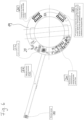
- Figure 1 shows a preferred embodiment of the invention, wherein the sensor hub 3 operates as a condition monitoring system using existing sensor cables 6 to communicate with a master device 1.
- the master device 1 and the sensor hub 3 communicate over existing power supply lines 6a provided by a servo motor drive 2 to power a servo motor feedback encoder 5 of a servo motor 9.
- the sensor hub 3 is connected via a communication interface 7 to the power supply lines 6a.
- the communication between the sensor hub 3 and the master device 1 is modulated over these power supply lines 6a, without interfering with the functionality of the servo motor feedback system.
- the motor 9 is powered by the motor drive 2 by a separate motor power cable 10.
- a gearbox 11 is attached to the motor 9.
- the servo motor feedback encoder 5 communicates with the motor drive 2 over separate encoder data lines 6b which are part of the sensor cable 6.
- At least one sensor 4 e.g. a vibration sensor, is connected to the sensor hub 3 via an interface 8, for example I2C, SPI, UART or analog interface. Additional sensors 4 for measuring temperature, torque, position, radar, humidity, etc., can be connected to the sensor hub 3.
- the master device 1 requests the sensor data from the sensor hub 3 and in some embodiments can be used as an edge device to perform condition monitoring and predictive maintenance calculations and can also be connected to a device-based or internet-based cloud application 25. With this solution, a condition monitoring system can easily be realized on existing machines, by using existing cables and connectors.
- Figure 2 shows a preferred embodiment of the invention, wherein the sensor hub 3 is used as a protocol converter for sensor data of the connected sensors 4, 13 and data of the second encoder 12.
- the basic configuration is similar to Figure 1 .
- the sensor hub 3 is connected via the communication interface 7 in parallel with the motor feedback encoder 5, and both communicate over a sensor cable 6 with the master device 1 on request.
- the sensor hub 3 acquires the data from the second encoder 12 and the sensor 13, which could be a torque sensor, on request of the master device 2, synchronized to the request of the first motor feedback encoder 5.
- the sensors 4, 13 and encoder 12 can be connected to the sensor hub for example via I2C, SPI, UART interface or analog interface, and the sensor hub 3 converts the data from the different sensors 4, 12 and 13 and encoder 12 to the protocol used for communication between the sensor hub 3 and the master device 1.
- This can be a RS485 protocol or a communication protocol described in EP 3 439 245 B1 .
- the master device 1 may be an external device or may be integrated into the motor drive 2.
- Figure 3 shows a preferred embodiment of the invention, wherein the sensor hub 3 is used for condition monitoring of several sensors or diagnostic systems.
- the sensor hub 3 allows a system setup with multiple encoders 5, 12 and a sensor 13, which can be a torque sensor connected to the sensor hub 3.
- the sensor hub 3 is connected via a communication interface 7 to the sensor cable 6 and enables data transmission to the master device 1 for position data of the first encoder 5 and the second encoder 12 and from a sensor 13 or a third encoder in a single motor control cycle.
- a fast data transmission, low overhead and dual channel data can be used for absolute safe position detection.
- Figure 5 shows a preferred embodiment of the invention, wherein the sensor hub 3 is used for sensor fusion.
- the sensor hub 3 is connected to several encoders 5, 12 and allows a system setup with the encoders 5, 12 to enable data transmission for position data of the first encoder 5, placed on a drive shaft, and position data of a second encoder 12 placed on the load shaft of a gear box 11.
- the position data of both encoders 5, 12 are latched at the same time via the sensor hub 3.
- the sensor hub 3 is connected via the communication interface 7 directly to the sensor cable 6.
- the sensor hub 3 and/or the master device 1 can calculate the torque value based on differences of the received position data of the encoders 5, 12 and can detect abnormalities to provide condition monitoring or predictive maintenance information.
- FIG. 6 shows a schematic drawing of the sensor hub embedded on a printed circuit board 19 of a servo motor assembly.
- the printed circuit board 19 is for example ring-shaped to be embedded at the back or front of a servo motor.
- the electronic components 20 of the sensor hub including a computing device 26 in form of a microcontroller unit (MCU), a (flexible) connector 21 for connecting a vibration sensor 4, additional connectors 22, 23 for connecting various sensors and encoders to the sensor hub and electronic components 24 forming a communication interface for communication with the master device over the electric power lines or data lines.
- MCU microcontroller unit
- additional connectors 22, 23 for connecting various sensors and encoders to the sensor hub
- electronic components 24 forming a communication interface for communication with the master device over the electric power lines or data lines.
Landscapes
- Engineering & Computer Science (AREA)
- Power Engineering (AREA)
- Microelectronics & Electronic Packaging (AREA)
- Computer Networks & Wireless Communication (AREA)
- Signal Processing (AREA)
- Computer Security & Cryptography (AREA)
- Health & Medical Sciences (AREA)
- Computing Systems (AREA)
- General Health & Medical Sciences (AREA)
- Medical Informatics (AREA)
- Arrangements For Transmission Of Measured Signals (AREA)
Claims (9)
- Offene Sensor-Hub (3)-Plattform für eine Servomotoranordnung, umfassendmindestens eine Sensor-Kommunikationsschnittstelle (8) zum Kommunizieren mit mindesten einem Sensor oder Kodierer (4, 12, 16),ein Rechnergerät (26) zum Auswerten und/oder Verarbeiten und/oder Umwandeln aus dem mindestens einen Sensor oder Kodierer (4, 12, 16) beschaffter Daten, undeine Kommunikationsschnittstelle (7) zum Kommunizieren mindestens mit einem Master-Gerät (1), wobei der Sensor-Hub (3) und das Master-Gerät (1) über ein einziges Kabel (6, 14) miteinander verbindbar sind,dadurch gekennzeichnet, dass die Kommunikationsschnittstelle (7) zum Master-Gerät (1) dazu ausgelegt ist, eine Echtzeit-Datenübertragung von Positionsdaten eines ersten Kodierers (5) und zusätzlicher Kodierer (12) oder Daten zusätzlicher Sensoren (4, 13) in einem einzigen Motor-Regelungszyklus bereitzustellen, und wobei die Sensor-Kommunikationsschnittstelle (8) dazu ausgelegt ist, eine synchrone Datenbeschaffung mindestens eines Sensors (4, 16) und mindestens eines Kodierers (5, 12) bereitzustellen.
- Sensor-Hub (3) gemäß Anspruch 1, dadurch gekennzeichnet, dass er über die Kommunikationsschnittstelle (7) mit dem ersten Kodierer (5) parallel geschaltet ist.
- Sensor-Hub (3) gemäß einem der Ansprüche 1 oder 2, dadurch
gekennzeichnet, dass die Kommunikationsschnittstelle (7) zum Master-Gerät (1) dazu ausgelegt ist, eine Kommunikation mittels eines bekannten Modulationsverfahrens über ein bestehendes Stromversorgungskabel (6a) bereitzustellen. - Sensor-Hub (3) gemäß Anspruch 3, dadurch gekennzeichnet, dass das Modulationsverfahren Amplituden-, Frequenz- oder Phasenmodulation einer Trägerfrequenz beinhaltet.
- Sensor-Hub (3) gemäß einem der Ansprüche 1 bis 4, dadurch
gekennzeichnet, dass die Kommunikationsschnittstelle (7) zum Master-Gerät (1) eine RS485-Schnittstelle ist. - Sensor-Hub (3) gemäß einem der Ansprüche 1 bis 5, dadurch
gekennzeichnet, dass der mindestens eine Sensor (4, 12, 16), der mit dem Sensor-Hub (3) verbunden ist, einen der folgenden Sensoren beinhaltet:
einen Erschütterungs- oder Vibrationssensor, einen Positionssensor (Kodierer), einen Drehmomentsensor, einen Temperatursensor, einen Motor-Bremssystem-Sensor. - Sensor-Hub (3) gemäß einem der Ansprüche 1 bis 6, dadurch
gekennzeichnet, dass das Master-Gerät (1) ein unabhängiges Gerät ist oder in ein Positionssensor-Steuergerät oder einen Motorantrieb (2) einer Servomotoranordnung integriert ist. - Sensor-Hub (3) gemäß einem der Ansprüche 1 bis 7, dadurch
gekennzeichnet, dass der Sensor-Hub (3) dazu ausgelegt ist, bei einer bestehenden Servomotoranordnung nachgerüstet zu werden und an ein bestehendes Kabel (6, 14) angeschlossen zu werden. - Verfahren zum zustandsbasierten Überwachen und zur vorausschauenden Wartung von Motoren, Zahnrädern und Maschinen unter der Verwendung des Sensor-Hubs (3) gemäß einem der Ansprüche 1 bis 8.
Priority Applications (1)
| Application Number | Priority Date | Filing Date | Title |
|---|---|---|---|
| CN202210118141.8A CN115001217A (zh) | 2021-02-16 | 2022-02-08 | 传感器集线器 |
Applications Claiming Priority (1)
| Application Number | Priority Date | Filing Date | Title |
|---|---|---|---|
| US202163149860P | 2021-02-16 | 2021-02-16 |
Publications (2)
| Publication Number | Publication Date |
|---|---|
| EP4044560A1 EP4044560A1 (de) | 2022-08-17 |
| EP4044560B1 true EP4044560B1 (de) | 2025-07-02 |
Family
ID=75801435
Family Applications (1)
| Application Number | Title | Priority Date | Filing Date |
|---|---|---|---|
| EP21171953.9A Active EP4044560B1 (de) | 2021-02-16 | 2021-05-04 | Sensor-hub |
Country Status (2)
| Country | Link |
|---|---|
| EP (1) | EP4044560B1 (de) |
| CN (1) | CN115001217A (de) |
Families Citing this family (2)
| Publication number | Priority date | Publication date | Assignee | Title |
|---|---|---|---|---|
| DE102022129341A1 (de) * | 2022-11-07 | 2024-05-08 | Sick Ag | Antriebssystem |
| DE102022129351A1 (de) * | 2022-11-07 | 2024-05-08 | Baumüller Nürnberg GmbH | Antriebssystem |
Citations (11)
| Publication number | Priority date | Publication date | Assignee | Title |
|---|---|---|---|---|
| EP1193926A2 (de) | 2000-09-27 | 2002-04-03 | Siemens Aktiengesellschaft | Verfahren und System zur Echtzeitkommunikation in einem Netz mit Ethernet-Physik |
| DE10047924B4 (de) | 2000-09-27 | 2004-08-05 | Siemens Ag | Antriebsregelung sowie Verfahren zur Vernetzung einer Regelungseinheit mit einem oder mehreren Gebersystemen |
| JP2004318491A (ja) | 2003-04-16 | 2004-11-11 | Yaskawa Electric Corp | フルクローズでの制御法 |
| EP2148178A1 (de) | 2008-07-23 | 2010-01-27 | SICK STEGMANN GmbH | Verfahren zur digitalen, bidirektionalen Datenübertragung |
| US20150112640A1 (en) | 2013-10-22 | 2015-04-23 | Nidec Avtron Automation Corporation | Machine diagnostic encoder |
| JP2016093024A (ja) | 2014-11-07 | 2016-05-23 | 株式会社ロボテック | モータ制御システムおよびモータの制御方法 |
| US9477221B1 (en) | 2015-06-02 | 2016-10-25 | Goodrich Corporation | Hybrid architecture and method for absolute position to quadrature synthesis for motion detection and control |
| US20190036731A1 (en) | 2017-07-31 | 2019-01-31 | Hengstler Gmbh | Data transmission method between a rotary encoder and a motor control device or an evualation unit |
| EP3462138A1 (de) | 2017-09-27 | 2019-04-03 | Rockwell Automation Technologies, Inc. | Plattenmontierte mikroelektromechanische system(mems)-sensoren für die motordiagnostik und analytik |
| WO2019155700A1 (ja) | 2018-02-06 | 2019-08-15 | 三菱電機株式会社 | サーボシステム、センサハブ及び産業用装置の診断方法 |
| EP3736973A1 (de) | 2019-05-10 | 2020-11-11 | Rockwell Automation Technologies, Inc. | System und verfahren zur bereitstellung einer sicheren begrenzten kraft, die leistung in einem motor erzeugt |
Family Cites Families (2)
| Publication number | Priority date | Publication date | Assignee | Title |
|---|---|---|---|---|
| CN201243362Y (zh) * | 2008-07-01 | 2009-05-20 | 中山市汉仁电子有限公司 | 一种采用电力线传输信号的网络摄像头 |
| US11632604B2 (en) * | 2019-05-22 | 2023-04-18 | Samsung Electronics Co., Ltd. | Sensor device and electronic device obtaining information from the sensor device |
-
2021
- 2021-05-04 EP EP21171953.9A patent/EP4044560B1/de active Active
-
2022
- 2022-02-08 CN CN202210118141.8A patent/CN115001217A/zh active Pending
Patent Citations (12)
| Publication number | Priority date | Publication date | Assignee | Title |
|---|---|---|---|---|
| EP1193926A2 (de) | 2000-09-27 | 2002-04-03 | Siemens Aktiengesellschaft | Verfahren und System zur Echtzeitkommunikation in einem Netz mit Ethernet-Physik |
| DE10047924B4 (de) | 2000-09-27 | 2004-08-05 | Siemens Ag | Antriebsregelung sowie Verfahren zur Vernetzung einer Regelungseinheit mit einem oder mehreren Gebersystemen |
| JP2004318491A (ja) | 2003-04-16 | 2004-11-11 | Yaskawa Electric Corp | フルクローズでの制御法 |
| EP2148178A1 (de) | 2008-07-23 | 2010-01-27 | SICK STEGMANN GmbH | Verfahren zur digitalen, bidirektionalen Datenübertragung |
| US20150112640A1 (en) | 2013-10-22 | 2015-04-23 | Nidec Avtron Automation Corporation | Machine diagnostic encoder |
| JP2016093024A (ja) | 2014-11-07 | 2016-05-23 | 株式会社ロボテック | モータ制御システムおよびモータの制御方法 |
| US9477221B1 (en) | 2015-06-02 | 2016-10-25 | Goodrich Corporation | Hybrid architecture and method for absolute position to quadrature synthesis for motion detection and control |
| US20190036731A1 (en) | 2017-07-31 | 2019-01-31 | Hengstler Gmbh | Data transmission method between a rotary encoder and a motor control device or an evualation unit |
| EP3439245B1 (de) | 2017-07-31 | 2020-12-30 | Hengstler GmbH | Datenübertragungsverfahren zwischen einem drehwinkelgeber und einer motorsteuereinrichtung oder einer auswerteeinheit |
| EP3462138A1 (de) | 2017-09-27 | 2019-04-03 | Rockwell Automation Technologies, Inc. | Plattenmontierte mikroelektromechanische system(mems)-sensoren für die motordiagnostik und analytik |
| WO2019155700A1 (ja) | 2018-02-06 | 2019-08-15 | 三菱電機株式会社 | サーボシステム、センサハブ及び産業用装置の診断方法 |
| EP3736973A1 (de) | 2019-05-10 | 2020-11-11 | Rockwell Automation Technologies, Inc. | System und verfahren zur bereitstellung einer sicheren begrenzten kraft, die leistung in einem motor erzeugt |
Non-Patent Citations (3)
| Title |
|---|
| ANONYMOUS: "EDS/EDM35 - EXCEPTIONAL PERFORMANCE FOR SERVO DRIVES: MOTOR FEEDBACK SYSTEMS WITH HIPERFACE DSL", SICK SENSOR INTELLIGENCE, 15 October 2019 (2019-10-15), XP093386575 |
| ANONYMOUS: "Einkabellösung - Hiperface DSL", HEIDRIVE MOTION & SYSTEMS, 1 March 2016 (2016-03-01), XP093386569 |
| D1 - „HIPERFACE DSL MANUAL"; version 3.13; 8013607/2010-02 |
Also Published As
| Publication number | Publication date |
|---|---|
| EP4044560A1 (de) | 2022-08-17 |
| CN115001217A (zh) | 2022-09-02 |
Similar Documents
| Publication | Publication Date | Title |
|---|---|---|
| EP4044560B1 (de) | Sensor-hub | |
| US20150143009A1 (en) | Use of an io link for linking field devices | |
| US10734926B2 (en) | Multi-axis motor control system, motor control apparatus, and motor control method | |
| JPH11299291A (ja) | 多軸モータ制御装置 | |
| US9910815B2 (en) | IO-Link adapter | |
| US11689439B2 (en) | Method and apparatus for communication with a motor or load mounted device in motion applications | |
| EP2588927A1 (de) | Anordnung und verfahren zur steuerung und/oder überwachung einer unterwasservorrichtung | |
| CN109463037B (zh) | 伺服系统、电机、绝对式编码器及其信号处理电路 | |
| CN112241138A (zh) | 逻辑控制装置以及列车控制系统 | |
| US9484846B2 (en) | Drive system with combined actuation of brake and encoder | |
| EP1193580A2 (de) | Gebersystem zur Lage-/Positionserfassung und/oder Geschwindigkeitserfassung und/oder Beschleunigungserfassung, darauf aufbauende Antriebsregelung sowie Verfahren zur Vernetzung einer Regelungseinheit mit einem oder mehreren Gebersystemen | |
| JP2023547801A (ja) | セーフティクリティカルプロセスを制御する装置 | |
| CN109327365B (zh) | 在转角传感器与发动机控制装置或分析单元之间的数据传递方法 | |
| US20170077991A1 (en) | Device for the transmission of signals | |
| CN111064393A (zh) | 一种多轴永磁同步电机控制装置 | |
| US7617011B2 (en) | Automation system | |
| CN102694489A (zh) | 马达控制系统及其方法与制动装置 | |
| CN216564982U (zh) | 电机驱动器及自动化设备 | |
| JP2020534624A (ja) | 車体組立のためのシステム | |
| CN106444530A (zh) | 一种集成modbus协议的交交变频控制板 | |
| JP2007267480A (ja) | サーボ制御装置とそれを利用するサーボシステム | |
| KR101938472B1 (ko) | 범용 인버터 확장 옵션 접속용 커넥터 단자를 활용한 디지털 속도제어 및 프로그래밍 기능을 지원하는 인버터 제어시스템 | |
| KR101803936B1 (ko) | 중앙 집중식과 분산 네트워크의 통합 모션 제어기 | |
| CN110221550B (zh) | 机器人系统 | |
| CN111684372B (zh) | 用于机器人的编码器、驱动器、控制器及机器人 |
Legal Events
| Date | Code | Title | Description |
|---|---|---|---|
| PUAI | Public reference made under article 153(3) epc to a published international application that has entered the european phase |
Free format text: ORIGINAL CODE: 0009012 |
|
| STAA | Information on the status of an ep patent application or granted ep patent |
Free format text: STATUS: THE APPLICATION HAS BEEN PUBLISHED |
|
| AK | Designated contracting states |
Kind code of ref document: A1 Designated state(s): AL AT BE BG CH CY CZ DE DK EE ES FI FR GB GR HR HU IE IS IT LI LT LU LV MC MK MT NL NO PL PT RO RS SE SI SK SM TR |
|
| STAA | Information on the status of an ep patent application or granted ep patent |
Free format text: STATUS: REQUEST FOR EXAMINATION WAS MADE |
|
| 17P | Request for examination filed |
Effective date: 20221014 |
|
| RBV | Designated contracting states (corrected) |
Designated state(s): AL AT BE BG CH CY CZ DE DK EE ES FI FR GB GR HR HU IE IS IT LI LT LU LV MC MK MT NL NO PL PT RO RS SE SI SK SM TR |
|
| STAA | Information on the status of an ep patent application or granted ep patent |
Free format text: STATUS: EXAMINATION IS IN PROGRESS |
|
| 17Q | First examination report despatched |
Effective date: 20230403 |
|
| REG | Reference to a national code |
Ref country code: DE Ref legal event code: R079 Free format text: PREVIOUS MAIN CLASS: H04L0029080000 Ipc: H04L0067120000 Ref country code: DE Ref legal event code: R079 Ref document number: 602021033179 Country of ref document: DE Free format text: PREVIOUS MAIN CLASS: H04L0029080000 Ipc: H04L0067120000 |
|
| GRAP | Despatch of communication of intention to grant a patent |
Free format text: ORIGINAL CODE: EPIDOSNIGR1 |
|
| STAA | Information on the status of an ep patent application or granted ep patent |
Free format text: STATUS: GRANT OF PATENT IS INTENDED |
|
| GRAS | Grant fee paid |
Free format text: ORIGINAL CODE: EPIDOSNIGR3 |
|
| RIC1 | Information provided on ipc code assigned before grant |
Ipc: H04L 67/565 20220101ALI20250123BHEP Ipc: H04L 69/08 20220101ALI20250123BHEP Ipc: H04L 67/12 20220101AFI20250123BHEP |
|
| INTG | Intention to grant announced |
Effective date: 20250130 |
|
| GRAA | (expected) grant |
Free format text: ORIGINAL CODE: 0009210 |
|
| STAA | Information on the status of an ep patent application or granted ep patent |
Free format text: STATUS: THE PATENT HAS BEEN GRANTED |
|
| AK | Designated contracting states |
Kind code of ref document: B1 Designated state(s): AL AT BE BG CH CY CZ DE DK EE ES FI FR GB GR HR HU IE IS IT LI LT LU LV MC MK MT NL NO PL PT RO RS SE SI SK SM TR |
|
| REG | Reference to a national code |
Ref country code: GB Ref legal event code: FG4D |
|
| REG | Reference to a national code |
Ref country code: CH Ref legal event code: EP |
|
| REG | Reference to a national code |
Ref country code: DE Ref legal event code: R096 Ref document number: 602021033179 Country of ref document: DE |
|
| REG | Reference to a national code |
Ref country code: IE Ref legal event code: FG4D |
|
| REG | Reference to a national code |
Ref country code: NL Ref legal event code: MP Effective date: 20250702 |
|
| PG25 | Lapsed in a contracting state [announced via postgrant information from national office to epo] |
Ref country code: PT Free format text: LAPSE BECAUSE OF FAILURE TO SUBMIT A TRANSLATION OF THE DESCRIPTION OR TO PAY THE FEE WITHIN THE PRESCRIBED TIME-LIMIT Effective date: 20251103 |
|
| PG25 | Lapsed in a contracting state [announced via postgrant information from national office to epo] |
Ref country code: NL Free format text: LAPSE BECAUSE OF FAILURE TO SUBMIT A TRANSLATION OF THE DESCRIPTION OR TO PAY THE FEE WITHIN THE PRESCRIBED TIME-LIMIT Effective date: 20250702 |
|
| REG | Reference to a national code |
Ref country code: AT Ref legal event code: MK05 Ref document number: 1810601 Country of ref document: AT Kind code of ref document: T Effective date: 20250702 |
|
| PG25 | Lapsed in a contracting state [announced via postgrant information from national office to epo] |
Ref country code: IS Free format text: LAPSE BECAUSE OF FAILURE TO SUBMIT A TRANSLATION OF THE DESCRIPTION OR TO PAY THE FEE WITHIN THE PRESCRIBED TIME-LIMIT Effective date: 20251102 |
|
| PG25 | Lapsed in a contracting state [announced via postgrant information from national office to epo] |
Ref country code: NO Free format text: LAPSE BECAUSE OF FAILURE TO SUBMIT A TRANSLATION OF THE DESCRIPTION OR TO PAY THE FEE WITHIN THE PRESCRIBED TIME-LIMIT Effective date: 20251002 |
|
| REG | Reference to a national code |
Ref country code: LT Ref legal event code: MG9D |
|
| PG25 | Lapsed in a contracting state [announced via postgrant information from national office to epo] |
Ref country code: AT Free format text: LAPSE BECAUSE OF FAILURE TO SUBMIT A TRANSLATION OF THE DESCRIPTION OR TO PAY THE FEE WITHIN THE PRESCRIBED TIME-LIMIT Effective date: 20250702 |
|
| PG25 | Lapsed in a contracting state [announced via postgrant information from national office to epo] |
Ref country code: FI Free format text: LAPSE BECAUSE OF FAILURE TO SUBMIT A TRANSLATION OF THE DESCRIPTION OR TO PAY THE FEE WITHIN THE PRESCRIBED TIME-LIMIT Effective date: 20250702 |
|
| PG25 | Lapsed in a contracting state [announced via postgrant information from national office to epo] |
Ref country code: HR Free format text: LAPSE BECAUSE OF FAILURE TO SUBMIT A TRANSLATION OF THE DESCRIPTION OR TO PAY THE FEE WITHIN THE PRESCRIBED TIME-LIMIT Effective date: 20250702 |
|
| PG25 | Lapsed in a contracting state [announced via postgrant information from national office to epo] |
Ref country code: GR Free format text: LAPSE BECAUSE OF FAILURE TO SUBMIT A TRANSLATION OF THE DESCRIPTION OR TO PAY THE FEE WITHIN THE PRESCRIBED TIME-LIMIT Effective date: 20251003 |
|
| PG25 | Lapsed in a contracting state [announced via postgrant information from national office to epo] |
Ref country code: SE Free format text: LAPSE BECAUSE OF FAILURE TO SUBMIT A TRANSLATION OF THE DESCRIPTION OR TO PAY THE FEE WITHIN THE PRESCRIBED TIME-LIMIT Effective date: 20250702 Ref country code: CZ Free format text: LAPSE BECAUSE OF FAILURE TO SUBMIT A TRANSLATION OF THE DESCRIPTION OR TO PAY THE FEE WITHIN THE PRESCRIBED TIME-LIMIT Effective date: 20250702 |
|
| PG25 | Lapsed in a contracting state [announced via postgrant information from national office to epo] |
Ref country code: LV Free format text: LAPSE BECAUSE OF FAILURE TO SUBMIT A TRANSLATION OF THE DESCRIPTION OR TO PAY THE FEE WITHIN THE PRESCRIBED TIME-LIMIT Effective date: 20250702 |
|
| PG25 | Lapsed in a contracting state [announced via postgrant information from national office to epo] |
Ref country code: PL Free format text: LAPSE BECAUSE OF FAILURE TO SUBMIT A TRANSLATION OF THE DESCRIPTION OR TO PAY THE FEE WITHIN THE PRESCRIBED TIME-LIMIT Effective date: 20250702 Ref country code: BG Free format text: LAPSE BECAUSE OF FAILURE TO SUBMIT A TRANSLATION OF THE DESCRIPTION OR TO PAY THE FEE WITHIN THE PRESCRIBED TIME-LIMIT Effective date: 20250702 |
|
| PG25 | Lapsed in a contracting state [announced via postgrant information from national office to epo] |
Ref country code: RS Free format text: LAPSE BECAUSE OF FAILURE TO SUBMIT A TRANSLATION OF THE DESCRIPTION OR TO PAY THE FEE WITHIN THE PRESCRIBED TIME-LIMIT Effective date: 20251002 |
|
| PG25 | Lapsed in a contracting state [announced via postgrant information from national office to epo] |
Ref country code: ES Free format text: LAPSE BECAUSE OF FAILURE TO SUBMIT A TRANSLATION OF THE DESCRIPTION OR TO PAY THE FEE WITHIN THE PRESCRIBED TIME-LIMIT Effective date: 20250702 |
|
| REG | Reference to a national code |
Ref country code: DE Ref legal event code: R082 Ref document number: 602021033179 Country of ref document: DE Representative=s name: DR. RIEBLING & PARTNER PATENTANWAELTE MBB, DE Ref country code: DE Ref legal event code: R026 Ref document number: 602021033179 Country of ref document: DE |
|
| PLBI | Opposition filed |
Free format text: ORIGINAL CODE: 0009260 |
|
| PG25 | Lapsed in a contracting state [announced via postgrant information from national office to epo] |
Ref country code: SM Free format text: LAPSE BECAUSE OF FAILURE TO SUBMIT A TRANSLATION OF THE DESCRIPTION OR TO PAY THE FEE WITHIN THE PRESCRIBED TIME-LIMIT Effective date: 20250702 |
|
| REG | Reference to a national code |
Ref country code: CH Ref legal event code: L11 Free format text: ST27 STATUS EVENT CODE: U-0-0-L10-L11 (AS PROVIDED BY THE NATIONAL OFFICE) Effective date: 20260409 |
|
| PLAB | Opposition data, opponent's data or that of the opponent's representative modified |
Free format text: ORIGINAL CODE: 0009299OPPO |
|
| PG25 | Lapsed in a contracting state [announced via postgrant information from national office to epo] |
Ref country code: DK Free format text: LAPSE BECAUSE OF FAILURE TO SUBMIT A TRANSLATION OF THE DESCRIPTION OR TO PAY THE FEE WITHIN THE PRESCRIBED TIME-LIMIT Effective date: 20250702 |
|
| PG25 | Lapsed in a contracting state [announced via postgrant information from national office to epo] |
Ref country code: IT Free format text: LAPSE BECAUSE OF FAILURE TO SUBMIT A TRANSLATION OF THE DESCRIPTION OR TO PAY THE FEE WITHIN THE PRESCRIBED TIME-LIMIT Effective date: 20250702 |
|
| REG | Reference to a national code |
Ref country code: CH Ref legal event code: L10 Free format text: ST27 STATUS EVENT CODE: U-0-0-L10-L00 (AS PROVIDED BY THE NATIONAL OFFICE) Effective date: 20260416 |