EP4044482A1 - Kommunikationsverfahren und kommunikationsvorrichtung - Google Patents
Kommunikationsverfahren und kommunikationsvorrichtung Download PDFInfo
- Publication number
- EP4044482A1 EP4044482A1 EP19951268.2A EP19951268A EP4044482A1 EP 4044482 A1 EP4044482 A1 EP 4044482A1 EP 19951268 A EP19951268 A EP 19951268A EP 4044482 A1 EP4044482 A1 EP 4044482A1
- Authority
- EP
- European Patent Office
- Prior art keywords
- cell
- indication information
- terminal device
- communications method
- state
- Prior art date
- Legal status (The legal status is an assumption and is not a legal conclusion. Google has not performed a legal analysis and makes no representation as to the accuracy of the status listed.)
- Withdrawn
Links
Images


Classifications
-
- H—ELECTRICITY
- H04—ELECTRIC COMMUNICATION TECHNIQUE
- H04W—WIRELESS COMMUNICATION NETWORKS
- H04W48/00—Access restriction; Network selection; Access point selection
- H04W48/16—Discovering, processing access restriction or access information
-
- H—ELECTRICITY
- H04—ELECTRIC COMMUNICATION TECHNIQUE
- H04L—TRANSMISSION OF DIGITAL INFORMATION, e.g. TELEGRAPHIC COMMUNICATION
- H04L5/00—Arrangements affording multiple use of the transmission path
- H04L5/0091—Signalling for the administration of the divided path, e.g. signalling of configuration information
- H04L5/0096—Indication of changes in allocation
- H04L5/0098—Signalling of the activation or deactivation of component carriers, subcarriers or frequency bands
-
- H—ELECTRICITY
- H04—ELECTRIC COMMUNICATION TECHNIQUE
- H04L—TRANSMISSION OF DIGITAL INFORMATION, e.g. TELEGRAPHIC COMMUNICATION
- H04L5/00—Arrangements affording multiple use of the transmission path
- H04L5/0001—Arrangements for dividing the transmission path
- H04L5/0003—Two-dimensional division
- H04L5/0005—Time-frequency
- H04L5/0007—Time-frequency the frequencies being orthogonal, e.g. OFDM(A) or DMT
- H04L5/001—Time-frequency the frequencies being orthogonal, e.g. OFDM(A) or DMT the frequencies being arranged in component carriers
-
- H—ELECTRICITY
- H04—ELECTRIC COMMUNICATION TECHNIQUE
- H04W—WIRELESS COMMUNICATION NETWORKS
- H04W24/00—Supervisory, monitoring or testing arrangements
- H04W24/10—Scheduling measurement reports ; Arrangements for measurement reports
-
- H—ELECTRICITY
- H04—ELECTRIC COMMUNICATION TECHNIQUE
- H04W—WIRELESS COMMUNICATION NETWORKS
- H04W56/00—Synchronisation arrangements
- H04W56/001—Synchronization between nodes
-
- H—ELECTRICITY
- H04—ELECTRIC COMMUNICATION TECHNIQUE
- H04L—TRANSMISSION OF DIGITAL INFORMATION, e.g. TELEGRAPHIC COMMUNICATION
- H04L5/00—Arrangements affording multiple use of the transmission path
- H04L5/003—Arrangements for allocating sub-channels of the transmission path
- H04L5/0048—Allocation of pilot signals, i.e. of signals known to the receiver
- H04L5/0051—Allocation of pilot signals, i.e. of signals known to the receiver of dedicated pilots, i.e. pilots destined for a single user or terminal
Definitions
- This application relates to the communications field, and more specifically, to a communications method and a communications apparatus.
- a terminal communicates with a network by using information carried on a carrier.
- the terminal may communicate with the network on a single carrier or a plurality of carriers.
- Carrier aggregation carrier aggregation, CA
- dual connectivity dual connectivity, DC
- a primary cell primary cell, PCell
- the PCell is responsible for radio resource control (radio resource control, RRC) communication with the terminal.
- a secondary cell secondary cell, SCell
- SCell is used to provide additional radio resources. There may be a plurality of SCells.
- SCells different from the PCell, can be used for data communication only after being activated.
- the network side may deactivate the SCells according to a deactivation command. How the network side efficiently manages and measures the SCells is an urgent problem to be resolved.
- This application provides a communications method and a communications apparatus, to help a network device implement efficient cell management.
- a communications method is provided.
- the communications method may be performed by a terminal device, or may be performed by a component (for example, a circuit or a chip) in a terminal device. This is not limited in this application.
- the communications method includes: receiving first indication information from a network device, where the first indication information indicates the terminal device to enter a first state in a first cell, the first state includes a synchronous measurable state, and the first indication information is sent by the network device by using a second cell; and entering the first state in the first cell based on the first indication information.
- the first indication information is sent to the terminal device, to indicate the terminal device to enter the synchronous measurable state in the first cell, so that the network device can manage or control a cell status.
- the first state may be understood as a "known (known) state".
- the known state can be understood as the synchronous measurable state. For details, refer to related descriptions in a protocol.
- the terminal device enters the first state in the first cell may be understood as that the terminal device maintains synchronization with the first cell and/or a signal used for synchronization is detectable.
- the first indication information includes a first field and/or a second field.
- the first field identifies the first cell
- the second field indicates an action (or a step, or a process) performed by the terminal device to enter the first state.
- the terminal device may learn, based on the first field, a cell in which the terminal device enters the first state, and may learn, based on the second field, an action that needs to be performed to enter the first state.
- the first cell and the second cell are configured by the network device for the terminal device, the second cell is an active cell, and the first cell is a deactivated cell.
- the communications method further includes: receiving second indication information from the network device, where the second indication information indicates the terminal device to activate the first cell.
- the terminal device may perform an activation process in the first cell based on the second indication information.
- the first indication information is received before the second indication information from the network device is received. After receiving the first indication information, the terminal device enters the synchronous measurable state in the first cell. In this way, before receiving an activation indication (the second indication information) from the network device, the terminal device has entered the synchronous measurable state in the first cell. In other words, before the network device sends the second indication information, the terminal device is already in the synchronous measurable state in the first cell. In this way, an activation latency of the first cell can be greatly shortened, and resource usage efficiency can be improved.
- the first indication information is received after the second indication information from the network device is received, and the first cell is in an out-of-synchronization state after being activated.
- the terminal device completes an activation process of the first cell.
- the terminal device learns that the first cell is still in the out-of-synchronization state by detecting the first cell.
- the terminal device receives the first indication information, and enters the synchronous measurable state in the first cell based on the first indication information.
- the communications method further includes: sending third indication information to the network device, where the third indication information indicates quality or strength of a signal of the first cell.
- the terminal device may send the third indication information to the network device, so that the network device adjusts the signal.
- the quality or strength of the signal of the first cell is less than a specific threshold
- the signal includes a synchronization signal block SSB or a channel state information-reference signal CSI-RS.
- the communications method further includes: sending fourth indication information to the network device, where the fourth indication information indicates that a status of the terminal device in the first cell is the first state.
- the terminal device after being in the first state in the first cell, the terminal device notifies the network device of the status of the terminal device in the first cell.
- the first indication information may be sent by using DCI, a MAC CE, an RRC, or the like, or may be sent by using newly defined signaling or a newly defined message.
- a sending manner is relatively flexible.
- the third indication information or the fourth indication information may be sent by using UCI, a MAC CE, or the like, or may be sent by using newly defined signaling or a newly defined message.
- a sending manner is relatively flexible.
- the first cell is a secondary cell
- the communications method further includes: performing downlink synchronization detection on the secondary cell; and sending fifth indication information to the network device based on a result of the downlink synchronization detection, where the fifth indication information indicates that the secondary cell is in a downlink out-of-synchronization state.
- the terminal device reports an out-of-synchronization indication to the network device, so that the network device manages the secondary cell.
- the communications method further includes: receiving configuration information from the network device, where the configuration information is used to perform the downlink synchronization detection on the secondary cell.
- the terminal device performs the downlink synchronization detection on the secondary cell by receiving the configuration information from the network device.
- the configuration information includes one or more of the following: a threshold of out-of-synchronization indication times, an out-of-synchronization determination timer, and a threshold of synchronization indication times.
- a communications method is provided.
- the communications method may be performed by a network device, or may be performed by a component (for example, a circuit or a chip) in a network device. This is not limited in this application.
- the communications method includes: determining first indication information, where the first indication information indicates a terminal device to enter a first state in a first cell, and the first state includes a synchronous measurable state; and sending the first indication information to the terminal device, where the first indication information is sent by using a second cell.
- the network device sends the first indication information to the terminal device, to indicate the terminal device to enter the synchronous measurable state in the first cell, so that the network device can manage or control a cell status.
- the first state may be equivalently replaced with a "known (known) state".
- known state For details about the meaning of "known state”, refer to related descriptions in a protocol.
- the terminal device enters the first state in the first cell may be understood as that the terminal device maintains synchronization with the first cell and/or a signal used for synchronization is detectable.
- the first indication information includes a first field and/or a second field.
- the first field identifies the first cell
- the second field indicates an action (or a step, or a process) performed by the terminal device to enter the first state.
- the terminal device may learn, based on the first field, a cell in which the terminal device enters the first state, and may learn, based on the second field, an action that needs to be performed to enter the first state.
- the first cell and the second cell are configured by the network device for the terminal device, the second cell is an active cell, and the first cell is a deactivated cell.
- the communications method further includes: sending second indication information to the terminal device, where the second indication information indicates the terminal device to activate the first cell.
- the network device sends an activation indication to the terminal device, to activate the first cell.
- the first indication information is sent before the second indication information is sent.
- the first cell Before the network device sends the second indication information, the first cell is already in the synchronous and measurable state. In this way, an activation latency of the first cell can be greatly shortened, and resource usage efficiency can be improved.
- the first indication information is sent after the second indication information is sent, and the first cell is in an out-of-synchronization state after being activated.
- the communications method further includes: receiving third indication information from the terminal device, where the third indication information indicates signal quality or strength of a first signal of the first cell.
- the network device may adjust the signal of the first cell based on the third indication information, so that the first cell can quickly enter the first state.
- the quality or strength of the signal of the first cell is less than a specific threshold
- the quality or strength of the signal of the first cell is less than a specific threshold
- the signal includes a synchronization signal block SSB or a channel state information-reference signal CSI-RS.
- the communications method further includes: receiving fourth indication information from the terminal device, where the fourth indication information indicates that a status of the terminal device in the first cell is the first state.
- the network device may learn the status of the terminal device in the first cell through reporting of the terminal device.
- the first indication information may be sent by using DCI, a MAC CE, an RRC, or the like, or may be sent by using newly defined signaling or a newly defined message.
- a sending manner is relatively flexible.
- the third indication information or the fourth indication information may be sent by using UCI, a MAC CE, or the like, or may be sent by using newly defined signaling or a newly defined message.
- a sending manner is relatively flexible.
- the first cell is a secondary cell
- the communications method further includes: receiving fifth indication information from the terminal device, where the fifth indication information indicates that the secondary cell is in a downlink out-of-synchronization state.
- the network device may manage the secondary cell based on the out-of-synchronization indication.
- the communications method further includes: sending configuration information to the terminal device, where the configuration information is used by the terminal device to perform downlink synchronization detection on the secondary cell.
- the network device may configure information used by the terminal device to detect the secondary cell.
- the configuration information includes one or more of the following: a threshold of out-of-synchronization indication times, an out-of-synchronization determination timer, and a threshold of synchronization indication times.
- a communications method is provided.
- the communications method may be performed by a terminal device, or may be performed by a component (for example, a circuit or a chip) in a terminal device. This is not limited in this application.
- the communications method includes: receiving configuration information from a network device, where the configuration information is used by the terminal device to perform downlink synchronization detection on a first cell, and the first cell is a secondary cell configured by the network device for the terminal device; performing downlink synchronization detection based on the configuration information; and sending indication information to the network device, where the indication information indicates that the first cell is in a downlink out-of-synchronization state.
- the terminal device reports an out-of-synchronization indication to the network device, so that the network device manages the secondary cell.
- the configuration information includes one or more of the following: a threshold of out-of-synchronization indication times, an out-of-synchronization determination timer, and a threshold of synchronization indication times.
- the communications method further includes: receiving first indication information from a network device, where the first indication information indicates the terminal device to enter a first state in the first cell, and the first state includes a synchronous measurable state.
- a communications method is provided.
- the communications method may be performed by a network device, or may be performed by a component (for example, a circuit or a chip) in a network device. This is not limited in this application.
- the communications method includes: sending configuration information to the terminal device, where the configuration information is used by the terminal device to perform downlink synchronization detection on a first cell, and the first cell is a secondary cell configured by a network device for the terminal device; and receiving indication information from the terminal device, where the indication information indicates that the secondary cell is in a downlink out-of-synchronization state.
- the network device can manage the secondary cell by configuring the terminal device to perform downlink synchronization detection on the secondary cell, and receive an out-of-synchronization indication reported by the terminal device.
- the configuration information includes one or more of the following: a threshold of out-of-synchronization indication times, an out-of-synchronization determination timer, and a threshold of synchronization indication times.
- the communications method further includes: determining, based on the indication information and a service requirement, whether to send first indication information to the terminal device, where the first indication information indicates the terminal device to enter a first state in the first cell, and the first state includes a synchronous measurable state.
- a communications apparatus includes modules or units configured to perform the method in any possible implementation of the first aspect or the third aspect.
- a communications apparatus includes a processor.
- the processor is coupled to a memory, and may be configured to execute instructions in the memory, to implement the method according to any one of the first aspect, the third aspect, or the possible implementations of the first aspect or the third aspect.
- the communications apparatus further includes the memory.
- the communications apparatus further includes a communications interface, and the processor is coupled to the communications interface.
- the communications apparatus is a terminal device.
- the communications interface may be a transceiver or an input/output interface.
- the communications apparatus is a chip disposed in a terminal device.
- the communications interface may be an input/output interface.
- the transceiver may be a transceiver circuit.
- the input/output interface may be an input/output circuit.
- a communications apparatus includes modules or units configured to perform the method in any possible implementation of the second aspect or the fourth aspect.
- a communications apparatus including a processor.
- the processor is coupled to a memory, and may be configured to execute instructions in the memory, to implement the method according to any one of the second aspect, the fourth aspect, or the possible implementations of the second aspect or the fourth aspect.
- the communications apparatus further includes the memory.
- the communications apparatus further includes a communications interface, and the processor is coupled to the communications interface.
- the communications apparatus is a network device.
- the communications interface may be a transceiver or an input/output interface.
- the communications apparatus is a chip disposed in a network device.
- the communications interface may be an input/output interface.
- the transceiver may be a transceiver circuit.
- the input/output interface may be an input/output circuit.
- a processor includes an input circuit, an output circuit, and a processing circuit.
- the processing circuit is configured to receive a signal via the input circuit, and transmit a signal via the output circuit, so that the processor is enabled to perform the method according to any possible implementation of the first aspect to the fourth aspect.
- the processor may be a chip
- the input circuit may be an input pin
- the output circuit may be an output pin
- the processing circuit may be a transistor, a gate circuit, a trigger, various logic circuits, or the like.
- An input signal received by the input circuit may be received and input by, for example, but not limited to, a receiver
- a signal output by the output circuit may be output to, for example, but not limited to, a transmitter and transmitted by the transmitter
- the input circuit and the output circuit may be a same circuit, which is used as the input circuit and the output circuit at different moments.
- Specific implementations of the processor and the circuits are not limited in embodiments of this application.
- an apparatus includes a processor and a memory.
- the processor is configured to read an instruction stored in the memory, receive a signal via a receiver, transmit a signal via a transmitter, and perform the method according to any possible implementation of the first aspect to the fourth aspect.
- processors there are one or more processors, and there are one or more memories.
- the memory may be integrated with the processor, or the memory and the processor are separately disposed.
- the memory may be a non-transitory (non-transitory) memory, for example, a read-only memory (read-only memory, ROM).
- the memory and the processor may be integrated on a same chip, or may be separately disposed on different chips.
- a type of the memory and a manner of disposing the memory and the processor are not limited in embodiments of this application.
- a related data exchange process for example, sending indication information, may be a process of outputting the indication information from the processor, and receiving capability information, may be a process of receiving the input capability information by the processor.
- data output by the processor may be output to the transmitter, and input data received by the processor may be from the receiver.
- the transmitter and the receiver may be collectively referred to as a transceiver.
- the apparatus may be a chip.
- the processor may be implemented by using hardware or software.
- the processor may be a logic circuit, an integrated circuit, or the like.
- the processor may be a general-purpose processor, and is implemented by reading software code stored in a memory.
- the memory may be integrated into the processor, or may be located outside the processor, and exists independently.
- a computer program product includes a computer program (which may also be referred to as code or instructions).
- a computer program which may also be referred to as code or instructions.
- a computer-readable medium stores a computer program (which may also be referred to as code or instructions).
- the computer program When the computer program is run on a computer, the computer is enabled to perform the method according to any one of the possible implementations of the first aspect to the fourth aspect.
- a communications system includes the foregoing network device and terminal device.
- a plurality of' means two or more, and another quantifier is similar to this.
- Transmission in embodiments of this application may be flexibly understood. That is, “transmission” may be understood as “sending” or “receiving”.
- a network device sends downlink control information or downlink data information, and a terminal device receives the downlink control information or downlink data information.
- the terminal device sends uplink control information or uplink data information, and the network device receives the uplink control information or the uplink data information.
- LTE long term evolution
- FDD frequency division duplex
- TDD time division duplex
- UMTS universal mobile telecommunication system
- WiMAX worldwide interoperability for microwave access
- 5G 5th generation
- NR new radio
- D2D device to device
- V2X vehicle to everything
- the terminal device in embodiments of this application may be user equipment (user equipment, UE), a subscriber station (subscriber station, SS), customer premise equipment (customer Premise Equipment, CPE), an access terminal, a subscriber unit, a subscriber station, a mobile station, a mobile station, a remote station, a remote terminal, a mobile device, a user terminal, a terminal, a wireless communications device, a user agent, or a user apparatus.
- user equipment user equipment
- UE subscriber station
- SS subscriber station
- CPE customer premise equipment
- an access terminal a subscriber unit, a subscriber station, a mobile station, a mobile station, a remote station, a remote terminal, a mobile device, a user terminal, a terminal, a wireless communications device, a user agent, or a user apparatus.
- the terminal device may alternatively be a cellular phone, a cordless telephone set, a Session Initiation Protocol (Session Initiation Protocol, SIP) phone, a wireless local loop (wireless local loop, WLL) station, a personal digital assistant (personal digital assistant, PDA), a handheld device having a wireless communications function, a computing device, another processing device connected to a wireless modem, a vehicle-mounted device, a wearable device, a terminal device in a future 5G network, a terminal device in a future evolved public land mobile network (public land mobile network, PLMN), or the like. This is not limited in the embodiments of this application.
- the terminal device may alternatively be a software and/or a hardware module deployed in an autonomous vehicle, an intelligent vehicle, a digital vehicle, or an internet-of-vehicles vehicle.
- the terminal device in embodiments of this application may alternatively be a D2D device, a V2X device, or a road side unit (road side unit, RSU).
- the network device in embodiments of this application may be a device configured to communicate with the terminal device.
- the network device may be a base transceiver station (base transceiver station, BTS) in a global system for mobile communications (global system for mobile communications, GSM) or a code division multiple access (code division multiple access, CDMA) system, or may be a NodeB (NodeB, NB) in a wideband code division multiple access (wideband code division multiple access, WCDMA) system, or may be an evolved NodeB (evolved NodeB, eNB or eNodeB) in the LTE system, or may be a radio controller in a cloud radio access network (cloud radio access network, CRAN) scenario.
- BTS base transceiver station
- GSM global system for mobile communications
- CDMA code division multiple access
- NodeB NodeB
- WCDMA wideband code division multiple access
- eNodeB evolved NodeB
- eNB evolved NodeB
- CRAN cloud radio
- the network device may be a relay node, an access point, a vehicle-mounted device, a wearable device, a network device in the future 5G network, a network device in the future evolved PLMN network, or the like.
- a network device may include a centralized unit (centralized unit, CU) node, or a distributed unit (distributed unit, DU) node, or a radio access network device including a CU node and a DU node.
- the network device may further include a radio unit (radio unit, RU).
- the CU implements some functions of the network device
- the DU implements some functions of the network device.
- the CU implements functions of a radio resource control (radio resource control, RRC) layer and a packet data convergence protocol (packet data convergence protocol, PDCP) layer
- the DU implements functions of a radio link control (radio link control, RLC) layer, a media access control (media access control, MAC) layer, and a physical (physical, PHY) layer.
- Information at the RRC layer eventually becomes information at the PHY layer, or is converted from information at the PHY layer. Therefore, in this architecture, higher layer signaling, for example, RRC layer signaling or PDCP layer signaling, may also be considered as being sent by the DU or sent by the DU and the RU.
- the CU may be classified into a network device in a radio access network, or may be classified into a network device in a core network (core network, CN). This is not limited herein.
- the terminal device or the network device may include a hardware layer, an operating system layer running above the hardware layer, and an application layer running above the operating system layer.
- the hardware layer includes hardware such as a central processing unit (central processing unit, CPU), a memory management unit (memory management unit, MMU), and a memory (also referred to as a main memory).
- An operating system may be any one or more types of computer operating systems that implement service processing through a process (process), for example, a Linux operating system, a Unix operating system, an Android operating system, an iOS operating system, or a Windows operating system.
- the application layer includes applications such as a browser, an address book, word processing software, and instant messaging software.
- an execution body of a method is not specifically limited in embodiments of this application, provided that a program that records code of the method provided in embodiments of this application can be run to perform communication according to the method provided in embodiments of this application.
- the execution body of the method provided in embodiments of this application may be the terminal device or the network device, or may be a functional module that can invoke the program and execute the program in the terminal device or the network device.
- aspects or features of this application may be implemented as a method, an apparatus, or a product that uses standard programming and/or engineering technologies.
- product used in this application covers a computer program that can be accessed from any computer-readable component, carrier, or medium.
- a computer-readable medium may include but is not limited to: a magnetic storage component (for example, a hard disk, a floppy disk, or a magnetic tape), an optical disc (for example, a compact disc (compact disc, CD) and a digital versatile disc (digital versatile disc, DVD)), a smart card, and a flash memory component (for example, an erasable programmable read-only memory (erasable programmable read-only memory, EPROM), a card, a stick, or a key drive).
- various storage media described in this specification may indicate one or more devices and/or other machine-readable media that are configured to store information.
- the term "machine-readable media” may include but is not limited to a wireless channel and various other media that can store, include, and/or carry instructions and/or data.
- the network device may communicate with the terminal device through carrier aggregation (carrier aggregation, CA).
- Carrier aggregation CA means aggregating two or more component carriers (component carriers, CC) together to serve one terminal device, to support a larger transmission bandwidth.
- CC component carriers
- CA is aggregation of a plurality of CCs on one network device.
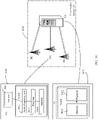
- FIG. 1 is a schematic diagram of a system architecture to which an embodiment of this application is applied.
- a network device 110 in FIG. 1 is used as an example. As shown in FIG. 1 , the network device 110 communicates with a terminal device 130 by using a CC1 and a CC3. Solutions in embodiments of this application may be applied to a CA scenario.
- each of two network devices has at least one CC.
- each of a primary network device (for example, a primary base station) and a secondary network device (for example, a secondary base station) has at least one CC, which is a primary cell (primary cell, PCell) and a primary secondary cell (primary second cell, PSCell).
- the PCell is determined during connection establishment (connection establishment) between the terminal device and the network device.
- the PCell is responsible for RRC communication with the terminal device, and is referred to as a primary cell.
- the PSCell is equivalent to a primary cell on the secondary network device, completes RRC communication between the terminal device and the secondary network device, is referred to as a primary secondary cell, and is a special SCell.
- the secondary network device may further have another secondary cell SCell.
- the terminal device may communicate with a network by using the primary network device and the secondary network device.
- the SCell is added/modified/released by using an RRC connection reconfiguration (RCConnectionReconfiguration) message after an initial security activation procedure (initial security activation procedure), and is used to provide additional radio resources.
- RRC connection reconfiguration RCConnectionReconfiguration
- No important RRC communication for example, important RRC communication includes RRC connection establishment and release
- SCell is referred to as a secondary cell.
- the architecture in FIG. 1 further includes a network device 120.
- the network device 120 communicates with the terminal device 130 by using a CC2 and a CC4.
- the CC1, the CC2, the CC3, and the CC4 are aggregated to provide a service for the terminal device 130.
- the network device 110 is a primary base station
- the network device 120 is a secondary base station
- each of the secondary base station and the secondary base station has at least one carrier, which is a PCell and a PSCell.
- the terminal device communicates with the network device by using a plurality of carriers (a plurality of cells).
- each downlink CC corresponds to an independent cell. It may also be said that one cell includes only one downlink CC. Generally, a downlink component carrier may be equivalent to one cell. One cell may include only one downlink carrier, or may include one downlink carrier and one uplink carrier, or may include one downlink carrier and two uplink carriers. Concepts of CC (which refers to downlink CC unless otherwise specified) and a cell in embodiments of this application may be interchanged.
- FIG. 1 is merely an example, and constitutes no limitation on this embodiment of this application.
- another proper communications architecture may be used. The following briefly describes terms used in embodiments of this application.
- a serving cell is a cell that provides a service for a terminal device. For example, the terminal device performs uplink transmission or downlink transmission in the serving cell. If the terminal device is in an RRC-connected (RRC_CONNECTED) state, but no CA is configured, the terminal device has only one serving cell, namely, a PCell. If the terminal device is in an RRC-connected state and CA is configured, a serving cell set of the terminal device includes a PCell and all SCells. That is, the serving cell may be either a PCell or an SCell. The PCell or the SCell may also be a serving cell.
- An SCell activation latency includes the following parts: T HARQ , T activation_time , and T CSI_Reporting .
- T HARQ is a latency caused because the terminal device generates, after receiving an SCell activation command, hybrid automatic repeat request (hybrid automatic repeat reQuest, HARQ) information for physical downlink shared channel (physical downlink shared channel, PDSCH) data that includes the SCell activation command.
- T activation_time is a latency caused because the terminal device performs SCell activation, for example, completing cell synchronization and/or automatic gain control (automatic gain control, AGC) setting.
- AGC automatic gain control
- T CSI_Reporting is a latency caused because the terminal device measures and feeds back channel state information (channel state information, CSI), that is, processing time of a CSI report.
- channel state information channel state information
- the T activation_time latency is usually the longest, especially in a scenario in which the SCell is in an unknown (unknown) state.
- An SCell whose measurement cycle (measurement cycle) is relatively long (for example, greater than 160 ms) and which is in the unknown state has a longer activation latency. If the SCell activation latency is too long, air interface resource usage of the SCell decreases.
- this application provides a communications method.
- a cell status can be managed and controlled by sending, to the terminal device, first indication information that indicates the terminal device to enter a first state. Further, in this embodiment of this application, before sending an activation command to the terminal device, the network device sends the first indication information to the terminal device, so that the terminal device enters a synchronous measurable state before activating the SCell. This helps reduce the SCell activation latency.
- FIG. 2 is a schematic interaction diagram of a communications method 200 to which an embodiment of this application is applied.
- a terminal device in FIG. 2 may be the terminal device (for example, the terminal device 130) in FIG. 1 , or may be an apparatus (for example, a processor, a chip, or a chip system) in the terminal device.
- a network device may be the network device (for example, the network device 110 or the network device 120) in FIG. 1 , or may be an apparatus (for example, a processor, a chip, or a chip system) in the network device.
- some or all of information exchanged between the terminal device and the network device in FIG. 2 may be carried in an existing message, channel, signal, or signaling, or may be carried in a newly defined message, channel, signal, or signaling. This is not specifically limited.
- the method 200 includes the following steps.
- the network device sends first indication information to the terminal device, where the first indication information indicates the terminal device to enter a first state in a first cell, the first state includes a synchronous measurable state, and the first indication information is sent by the network device by using a second cell.
- the terminal device receives the first indication information from the network device.
- the first state may be understood as a "known (known) state".
- the "known state” may be understood as the synchronous measurable state.
- 3 rd generation partnership project the 3 rd generation partnership project, 3GPP
- 3GPP 3 rd generation partnership project
- the SCell is known, that is, the SCell is in the known state if the SCell meets at least one of the following conditions:
- Each related SSB can provide information about a synchronization signal-reference signal received power (synchronization signal-reference signal receiving power, SS-RSRP), synchronization signal-reference signal received quality (synchronization signal-reference signal receiving quality, SS-RSRQ), a synchronization signal-signal to interference plus noise ratio (synchronization signal-signal to interference plus noise ratio, SS-SINR) of a related frequency band, or information related to the synchronization signal block received power (synchronization signal block receiving power, SSB_RP) and SSB ⁇ s/Iot meets a certain condition (for example, the information meets a certain threshold requirement, and in-band measurement meets a certain threshold requirement, where the threshold requirement may be related to the frequency band and SCS of the SSB, for details, refer to 3GPP TS 38.133 version 16.1.0 Annex B.2.2 Table B.2.2-
- the terminal device enters a first state in a first cell may be understood as: The terminal device maintains synchronization with the first cell, and/or a signal used for synchronization may be detected by the terminal device.
- the signal used for synchronization may include an SSB or a channel state information-reference signal (channel state information-reference signal, CSI-RS).
- a state of the terminal device before the terminal device enters the first state is not specifically limited in this embodiment of this application.
- the terminal device Before entering the first state, the terminal device may be in the first state, or may be in a second state.
- the second state may be understood as a state different from or opposite to the first state. For example, the second state is a non-synchronization state.
- the first cell may be an SCell, or a primary secondary cell PSCell.
- S202 The terminal device enters the first state in the first cell based on the first indication information.
- the network device sends the first indication information to the terminal device by using the second cell, where the first indication information indicates the terminal device to enter the synchronous measurable state in the first cell.
- the terminal device After receiving the first indication information, the terminal device enters the synchronous measurable state in the first cell based on the first indication information. For example, the terminal device may switch from the non-synchronization state to the synchronous measurable state. In this way, a cell status can be managed and controlled by introducing the first indication information.
- the second cell is an activated cell
- the first cell is a deactivated cell and has a relatively large measurement cycle.
- the network device sends the first indication information to the terminal device by using the activated cell, so that the terminal device enters the synchronous measurable state in the first cell.
- the second cell is a primary cell, or an activated secondary cell, or an activated primary secondary cell
- the first cell is a deactivated secondary cell.
- the network device may send the first indication information to the terminal device through a physical downlink control channel (physical downlink control channel, PDCCH).
- a physical downlink control channel physical downlink control channel, PDCCH
- the network device may send the first indication information to the terminal device by using an existing downlink control information (downlink control information, DCI) format or a newly defined DCI format.
- DCI downlink control information
- the DCI format may include a DCI format 1_0 (DCI format 1_0), a DCI format 1_1 (DCI format 1_1), a DCI format 0_0, or a DCI format 0_1.
- the DCI format may include a DCI format 1 series (DCI format 1 series) or a DCI format 2 series (DCI format 2 series).
- the DCI format 1 series may be represented as a DCI format 1/1A/1B/1C/1D, a DCI format 6-1A/6-1B, or DCI format 7-1A/7-1B/7-1C/7-1D/7-1E/7-1F/7-1G.
- the DCI format 2 series may be represented as a DCI format 2/2A/2B/2C/2D or a DCI format 6-2.
- the network device may scramble a cyclic redundancy check (cyclic redundancy check, CRC) in a DCI format by using an existing radio network temporary identifier (radio network temporary identifier, RNTI) or a newly defined RNTI, for example, an X-RNTI.
- CRC cyclic redundancy check
- the existing RNTI includes a cell-radio network temporary identifier (cell-radio network temporary identifier, C-RNTI), a paging-radio network temporary identifier (paging-radio network temporary identifier, P-RNTI), or a system information-radio network temporary identifier (system information radio network temporary identifier, SI-RNTI).
- C-RNTI cell-radio network temporary identifier
- P-RNTI paging-radio network temporary identifier
- SI-RNTI system information radio network temporary identifier
- the first indication information includes a first field and/or a second field.
- the first field identifies the first cell, and the second field indicates an action (or a step, or a process) performed by the terminal device to enter the first state.
- the first field may be implemented by using a cell indication, and the cell indication identifies the first cell.
- the first indication information includes a cell indication information field, and the first field may be an information bit in the cell indication information field. It is assumed that a maximum of 16 cells are supported, and one cell thereof is a PCell.
- An example in which the cell indication information field includes a bitmap (bitmap) of 15 bits is used. The 15 bits respectively corresponds to 15 SCells, which are respectively SCell 1 to SCell 15. The 15 bits may separately indicate the 15 SCells.
- the network device configures one secondary cell index (SCell index) for each SCell.
- the network device configures 15 SCells for the terminal device, and indexes of the SCells are 1 to 15 sequentially. That is, an SCell index of SCell 1 is 1, an SCell index of SCell 2 is 2, and so on.
- Cell indication information of the 15 bits sequentially corresponds to the 15 SCells based on bit locations. A value of each bit indicates an operation performed on a corresponding cell. For example, if the information bit is "1", it indicates that the operation performed on the corresponding cell is started, and if the information bit is "0", it indicates that the operation performed on the corresponding cell is not started.
- the first cell is one of the 15 SCells, and a value of a bit corresponding to the first cell is 1, it indicates that an operation performed on the first cell is started.
- the 15 bits are used as an example for description in the foregoing indication, and this does not constitute a limitation on this embodiment of this application.
- bits occupied by the cell indication information field may be reduced.
- four bits may alternatively be used to indicate the operation performed on the corresponding cell, and the four bits may respectively indicate four cells.
- the network device may correspond single-cell indication information to an SCell index of an SCell.
- 4-bit cell indication information is used, and a value indicated by the 4-bit cell indication information is the SCell index.
- the single-cell indication information may further reuse a carrier indicator field (carrier indicator field, CIF) information field in existing DCI, send the first indication information to the terminal device, and indicate the cell to the terminal device by using the DCI.
- a CIF is a cell identifier configured by the network device for an SCell in cross-carrier scheduling.
- CIF-based cross-carrier scheduling allows a PDCCH of one serving cell to schedule radio resources of another serving cell.
- a cell used to send a PDCCH is referred to as a scheduling cell, and a cell whose resources are scheduled is referred to as a scheduled cell. That is, control information is transmitted on one CC, and corresponding data is transmitted on another CC.
- a PCell is not scheduled by another carrier, and an SCell may be configured to schedule another SCell carrier, or may be configured to be scheduled by a carrier of another SCell.
- one cell may schedule a plurality of other cells.
- an existing protocol supports scheduling a plurality of other cells.
- a cell can schedule a plurality of cells at the same time.
- the network device allocates a CIF to a scheduled cell, and the CIF indicates, when the scheduled cell sends a PDCCH, a cell for which PDCCH information is served. Therefore, the CIF may also be considered as an identifier of the scheduled cell.
- CIFs with different bits can be defined based on a quantity of scheduled cells supported by a cell. For example, the existing CIF has 3 bits, and supports scheduling of seven cells. When a greater quantity of scheduled cells needs to be supported, the CIF may expand a quantity of bits. This is not limited in this embodiment of this application.
- the second field may be implemented by using a procedure indication (procedure indication) field.
- a procedure indication indicates an action performed by the terminal device after entering the first state.
- the action performed by the terminal device when entering the first state includes one or more of the following: cell search (coarse synchronization), downlink synchronization (fine time and frequency synchronization), AGC adjustment, CSI measurement, and beam sweeping.
- the first indication information includes the first field and the second field. That is, the first indication information not only includes a field identifies a cell, but also includes a field of the action that needs to be performed for entering the first state. In this way, the terminal device may learn, based on the first indication information, a cell in which the terminal device enters the first state and an action that needs to be performed to enter the first state.
- the first indication information includes the first field.
- the action that needs to be performed by the terminal device to enter the first state may be default.
- the network device and the terminal device pre-agree on, in a protocol, the action that needs to be performed by the terminal device to enter the first state.
- the terminal device After receiving the first indication information, the terminal device obtains the first cell identified by the first field in the first indication information, and performs, in the first cell, the default action that needs to be performed for entering the first state.
- the default action includes downlink synchronization, AGC adjustment, and CSI measurement.
- the first indication information includes the second field.
- the first cell may be a default cell.
- the network device and the terminal device pre-agree on the first cell in a protocol.
- the terminal device performs, in the default cell based on the second field, the action that needs to be performed for entering the first state.
- the default cell may be a cell corresponding to a minimum or a maximum SCell index value configured by the network device for the terminal device.
- the first indication information may further include another information field.
- the first indication information may further include one or more of the following information fields: a semi-persistent channel state information-reference signal (semi-persistent channel state information-reference signal, SP-CSI-RS) resource set identifier (resource set ID), a BWP indication (indication), a CSI trigger (trigger) indication, and a reserved field (or reserved bits Reserved bits).
- SP-CSI-RS semi-persistent channel state information-reference signal
- SP-CSI-RS resource set identifier
- BWP indication indication
- CSI trigger CSI trigger
- reserved field or reserved bits Reserved bits
- the SP-CSI-RS resource set ID indicates an index NZP-CSI-RS-ResourceSet of a semi-persistent non-zero power channel state information-reference signal resource (non-zero power channel state information-reference signal resource, NZP CSI-RS resource) set.
- the index indicates a CSI-RS resource used by the terminal device to perform synchronization, AGC adjustment, or CSI measurement.
- the BWP indication indicates a BWP of a cell on which an indication operation is performed.
- the CSI trigger indicates triggering of an aperiodic CSI-RS. For example, six bits are used to indicate triggering of one CSI-RS in 64 valid trigger states (TriggerStates).
- the reserved field means bits padded when a DCI size is aligned with a size of an existing DCI format.
- a purpose of introducing the reserved field is: A quantity of blind detection times of a PDCCH of the terminal device is not increased, so that a size of a newly designed DCI format or a reused DCI format is aligned with the size of the existing DCI format.
- a size of the DCI format 1_1 needs to be consistent with a size of a DCI format 1_1 used for downlink data scheduling.
- the DCI format 1_1 is merely used as an example for description herein, and this does not constitute a limitation on this embodiment of this application. Actually, if the network device sends the first indication information by using another DCI format, a principle of aligning DCI sizes also needs to be met.
- the first indication information may further include acknowledgment information.
- the acknowledgment information is a basis for determining the first indication information by the terminal device. Specifically, when the network device reuses the first indication information by using the existing DCI format, the terminal device needs to confirm that the DCI is the first indication information based on the acknowledgment information, that is, confirm that the DCI indicates the terminal device to enter the first state in the first cell.
- the acknowledgment information may be determined by scrambling the CRC in the DCI format by using the newly defined RNTI, or may be determined based on a specific value of a specific DCI information field, or may be determined by using a combination of the two. This is not specifically limited.
- the acknowledgment information may be determined by using one or more of the following information fields: a time domain resource assignment (time domain resource assignment, TDRA), a frequency domain resource assignment (frequency domain resource assignment, FDRA), a HARQ process number (process number), a redundancy version (redundancy version, RV), a modulation and coding scheme (modulation and coding scheme, MCS), a new data indicator (new data indicator, NDI), transmit power control (transmit power control, TPC) (which may be TPC of a physical uplink shared channel (physical uplink shared channel, PUSCH) or TPC of a physical uplink control channel (physical uplink control channel, PUCCH)), and a frequency hopping flag (frequency hopping flag).
- TPC transmit power control
- Table 1 is an implementation of the first indication information.
- Table 1 Information field Quantity of bits Meaning Identifier for DCI formats 1 Downlink data scheduling indication TDRA Variable Variable Time domain resource indication Cell indication 15 or 4 Cell indication BWP indication 0 or 2 BWP index indication
- Procedure indication 3 000 all possible processes in which an SCell is known, which are implemented and determined by UE 001: cell search (coarse synchronization) 010: downlink synchronization (fine time and frequency synchronization) 011: AGC adjustment 100: CSI measurement 101: beam sweeping CSI trigger 6 Asynchronous CSI-RS trigger SP-CSI-RS resource set ID 6 Semi-persistent CSI-RS resource set activation Reserved bits Variable Reserved bits or padding bits
- the first indication information includes the following fields: an identifier for DCI formats, a TDRA, a cell indication (corresponding to the foregoing first field), a BWP indication, a procedure indication (corresponding to the foregoing second field), a CSI trigger, an SP-CSI-RS resource set ID, and reserved bits. It may be understood that an example in which a quantity of bits of one cell is indicated is used for description of a quantity of bits of the BWP indication, the procedure indication, the CSI trigger, and the SP-CSI-RS resource set ID shown in Table 1. When independent information of a plurality of cells needs to be indicated, a quantity of bits of the plurality of cells needs to be described proportionately.
- a uniform set of indication information may alternatively be used. This is not limited.
- the TDRA in Table 1 is used as the acknowledgment information of the first indication information. For example, when detecting that every bit of information about a TDRA field in PDCCH information in the DCI format 1_0 scrambled by using a C-RNTI is '1', the terminal device determines that the PDCCH information is the first indication information.
- each field in Table 1 may have another value.
- the network device may send the first indication information to the terminal device by using a medium access control control element (medium access control control element, MAC CE).
- the first indication information may be sent by using a fixed-length MAC CE. That is, the MAC CE carrying the first indication information may include the first field and/or the second field. For meanings of the first field and the second field, refer to the foregoing descriptions.
- the MAC CE carrying the first indication information may further include an indication, for example, a reserved field and a CSI trigger.
- FIG. 3 and FIG. 4 shows an example of the MAC CE carrying the first indication information.
- the MAC CE carrying the first indication information includes the following fields: a field Ci (a value of i ranges from 1 to 15), reserved bits Rs, a CSI trigger, and a procedure indication. Meaning of Ci is as follows: If an SCell having an SCell index i is configured for RRC, the field Ci indicates indication information of the SCell having an SCell index i. If no SCell having an SCell index i is configured for RRC, a MAC entity of the terminal device ignores the field Ci. R is a reserved bit and is set to 0. For meanings of the procedure indication and the CSI trigger, refer to the foregoing descriptions. Details are not described herein again.
- the MAC CE carrying the first indication information includes the following fields: a serving cell (serving cell) ID, a BWP ID, reserved bits Rs, a procedure indication, and an SP-CSI-RS resource set ID.
- a value corresponding to the serving cell ID is an SCell index, indicating that an SCell with an SCell index is configured for RRC.
- the BWP ID indicates a downlink DL BWP in a corresponding SCell.
- FIG. 3 and FIG. 4 are provided merely for helping a person skilled in the art understand embodiments of this application, instead of limiting embodiments of this application to specific scenarios shown in the examples.
- a person skilled in the art can make various equivalent modifications or changes according to the examples shown in FIG. 3 and FIG. 4 , and such modifications or changes also fall within the scope of embodiments of this application.
- the terminal device may further receive an indication from the network device used to activate the first cell.
- the method 200 further includes the following step:
- the network device sends second indication information to the terminal device, where the second indication information indicates the terminal device to activate the first cell.
- the terminal device receives the second indication information from the network device.
- the terminal device may perform an activation process in the first cell based on the second indication information.
- the terminal device may send a valid CSI report to the network device, to complete activation of the first cell.
- steps S203 and S202 are not limited in the example in FIG. 2 .
- a sequence of receiving the first indication information and the second indication information by the terminal device is not limited in embodiments of this application.
- the first indication information is received before the second indication information from the network device is received.
- the network device sends the first indication information before sending the second indication information.
- the network device enables the terminal device to complete a synchronization process with the first cell in advance.
- the network device may alternatively enable the terminal device to complete one or more of the following processes in the first cell in advance: AGC adjustment, beam sweeping, and CSI measurement.
- the terminal device After receiving the first indication information, the terminal device enters the synchronous measurable state in the first cell. Before receiving an activation indication from the network device, the terminal device has entered the synchronous measurable state in the first cell. In other words, before the network device sends the second indication information, the terminal device is already in the synchronous measurable state in the first cell. In this way, an activation latency of the first cell can be greatly shortened (that is, a latency of the activation process of the first cell is shortened), and resource usage efficiency can be improved.
- the first cell is an SCell.
- the SCell When the SCell is in the deactivated state, the following behavior may be added to the terminal device: monitoring a PDCCH serving the SCell; and measuring CSI-RSs on the SCell, where the CSI-RSs include periodic, semi-persistent, and aperiodic CSI-RSs.
- a new SCell state may be introduced, for example, an enhanced deactivated (enhanced deactivated) state, and the terminal device may perform the following behavior: monitoring a PDCCH serving the SCell; and measuring CSI-RSs on the SCell, where the CSI-RSs include periodic, semi-persistent, and aperiodic CSI-RSs.
- the first indication information is received after the second indication information from the network device is received.
- the first indication information may be used by the network device to control a status, for example, a synchronization state between the terminal device and the network.
- the terminal device After receiving the second indication information, the terminal device completes the activation process of the first cell. Then, the first cell enters the active state. In a period of time, the synchronization state between the network device and the terminal device changes as a communications service between the network device and the terminal device changes.
- the terminal device may learn, by detecting the first cell, that the first cell is in the out-of-synchronization state. The terminal device receives the first indication information, and then enters the synchronous measurable state in the first cell based on the first indication information.
- the terminal device may detect a signal of the first cell, and report quality of the signal of the first cell to the network device.
- the method 200 further includes: The terminal device sends third indication information to the network device, where the third indication information indicates the quality or strength of the signal of the first cell.
- the terminal device may report the third indication information to the network device.
- Whether the signal of the first cell is abnormal may be determined in the following manner: If it is detected that the quality, the strength, a signal-to-noise ratio, or a signal-to-interference ratio of the first cell is less than a corresponding threshold, it is considered that the signal of the first cell is abnormal.
- the terminal device may not report the third indication information to the network device.
- the terminal device may detect a signal of the first cell used for synchronization, AGC adjustment, and CSI measurement, for example, an SSB or a CSI-RS, to determine whether the first cell is abnormal.
- a signal of the first cell used for synchronization, AGC adjustment, and CSI measurement for example, an SSB or a CSI-RS
- the third indication information may include a cell indication, which indicates a cell whose signal is abnormal.
- the third indication information may alternatively include a signal abnormal indication, which indicates a signal that is abnormal.
- the network device may adjust the signal of the first cell, so that the terminal device can quickly enter the first state in the first cell.
- the terminal device may also report the third indication information to the network device.
- the method 200 further includes: The terminal device sends fourth indication information to the network device, where the fourth indication information indicates that a status of the terminal device in the first cell is the first state.
- the network device receives the fourth indication information from the terminal device.
- the terminal device sends the fourth indication information to the network device, so that the network device learns that the terminal device is already in the first state in the first cell. In this way, the network device may schedule the terminal device in the first cell to perform transmission.
- the fourth indication information may include a cell indication (that indicates the first cell) and a field that indicates whether the cell enters the first state. For example, when a value of the field that indicates whether the cell enters the first state is 0, it indicates that the first cell is not in the synchronous measurable state, and when the value of the field is 1, it indicates that the first cell is in the synchronous measurable state.
- the third indication information and/or the fourth indication information may be sent by sharing a same PUCCH resource or a same PUSCH resource as uplink control information (uplink control information, UCI).
- UCI uplink control information
- Existing UCI information includes a scheduling request (scheduling request, SR), a HARQ, and channel state information (channel state information, CSI).
- the third indication information and/or the fourth indication information in this embodiment of this application may be used as new UCI information, for example, a cell status (cell status, CST).
- the terminal device may send the UCI information by using the PUSCH to piggyback (piggyback) the UCI information based on an indication of the network.
- the third indication information and/or the fourth indication information and other uplink control information UCI may undergo joint channel coding, or may be separately coded and then jointly sent. This is not specifically limited.
- the third indication information and the fourth indication information may also be separately sent by using a MAC CE.
- a difference between the first indication information and the third indication information or the fourth indication information is that the MAC CE carrying the first indication information is a downlink MAC CE, a value of a logical channel identifier (logical channel identifier, LCID) may be any one of 33 to 46, the MAC CE carrying the third indication information or the fourth indication information is an uplink MAC CE, and a value of an LCID may be any one of 33 to 51.
- a logical channel identifier logical channel identifier, LCID
- FIG. 5 is a schematic diagram of an example of the MAC CE carrying the third indication information.
- the MAC CE carrying the third indication information may be a MAC CE of a fixed length.
- the MAC CE carrying the third indication information includes the following fields: a serving cell (serving cell) ID, a reserved bit R, a CSI-RS, and an SSB.
- FIG. 6 is a schematic diagram of an example of the MAC CE carrying the fourth indication information.
- the MAC CE carrying the fourth indication information may be a MAC CE of a fixed length.
- the MAC CE carrying the fourth indication information includes the following fields: a serving cell (serving cell) ID, reserved bits Rs, and an ST (status).
- the ST field indicates whether a cell is in the first state.
- FIG. 5 and FIG. 6 are provided merely for helping a person skilled in the art understand embodiments of this application, instead of limiting embodiments of this application to specific scenarios shown in the examples.
- a person skilled in the art can make various equivalent modifications or changes according to the examples shown in FIG. 5 and FIG. 6 , and such modifications or changes also fall within the scope of embodiments of this application.
- FIG. 7 is a schematic interaction diagram of a communications method 700 to which another embodiment of this application is applied. It may be understood that a terminal device in FIG. 7 may be the terminal device (for example, the terminal device 130) in FIG. 1 , or may be an apparatus (for example, a processor, a chip, or a chip system) in the terminal device.
- a network device may be the network device (for example, the network device 110 or the network device 120) in FIG.
- the method 700 includes the following steps.
- the network device sends configuration information to the terminal device, where the configuration information is used by the terminal device to perform downlink synchronization detection on a first cell, and the first cell is a secondary cell configured by the network device for the terminal device.
- the terminal device receives the configuration information from the network device.
- the configuration information includes one or more of the following: a threshold of out-of-synchronization indication times, an out-of-synchronization determination timer, and a threshold of synchronization indication times.
- the network device may configure a same parameter value or different parameter values for different SCells. For example, a threshold of out-of-synchronization indication times configured by the network device for an SCell is N310-S, an out-of-synchronization determination timer is T310-S, and a threshold of synchronization recovery indication times is N311-S, where S represents corresponding to one SCell.
- the terminal device performs downlink synchronization detection based on the configuration information.
- the terminal device sends an out-of-synchronization signal (out of sync) and a synchronization signal (In Sync) to a higher layer by using a physical layer.
- the higher layer of the terminal device determines, with reference to the parameters N310-S, N311-S, and the timer T310-S that are configured by the network device, whether the SCell is in a downlink synchronization state.
- the higher layer of the terminal device may report the SCell to the network device by using an activated cell.
- the higher layer of the terminal device After receiving, in the synchronization state, an out-of-synchronization indication (out-of-sync indication) reported by the physical layer of the terminal device for N310-S continuous times, the higher layer of the terminal device starts the T310-S timer. Before the T310-S timer expires, if the synchronization indication (in-sync indication) is received for N311-S times, the terminal device considers that the synchronization state is restored; otherwise, after the T310-S timer expires, the terminal device is triggered to perform S703. Parameter configurations of the N310-S, N311-S, and T310-S are provided by the network device.
- the terminal device sends first indication information to the network device, where the first indication information indicates that the first cell is in a downlink out-of-synchronization state.
- the network device receives the first indication information from the terminal device.
- the terminal device performs out-of-synchronization detection on a secondary cell, and when detecting that the secondary cell is in the downlink out-of-synchronization state, the terminal device sends indication information to the network device, to provide information for the network device to manage the secondary cell.
- the method 700 further includes: The network device determines, based on the first indication information and a service requirement, whether to send second indication information to the terminal device, where the second indication information indicates the terminal device to enter a first state in the first cell, and the first state includes a synchronous measurable state. It may be understood that for a description of the second indication information in the method 700, refer to the description of the first indication information in the foregoing method 200. To avoid redundancy, details are not described herein again.
- the network device may determine, based on the service requirement, whether a plurality of carriers are required for sending, and determine whether to send the second indication information to the terminal device, to flexibly manage the secondary cell.
- the network device determines to perform sending on the plurality of carriers.
- the network device determines to activate the first cell, and sends the first indication information to the terminal device in advance, so that the first cell enters the synchronous measurable state.
- the network device can efficiently manage the secondary cell by learning out-of-synchronization information of the secondary cell that is reported by the terminal device.
- some optional features in embodiments of this application may be independently implemented without depending on another feature, for example, a solution on which the optional features are currently based, to resolve a corresponding technical problem and achieve a corresponding effect.
- the optional features are combined with another feature based on a requirement.
- an apparatus provided in embodiments of this application may also correspondingly implement these features or functions. Details are not described herein.
- an embodiment mentioned in the entire specification means that particular features, structures, or characteristics related to the embodiment are included in at least one embodiment of this application. Therefore, embodiments in the entire specification are not necessarily same embodiments. In addition, these particular features, structures, or characteristics may be combined in one or more embodiments by using any appropriate manner.
- sequence numbers of the foregoing processes do not mean execution sequences in various embodiments of this application.
- the execution sequences of the processes should be determined based on functions and internal logic of the processes. Numbers or sequence numbers in the foregoing processes are merely used for differentiation for ease of description, and should not constitute any limitation on an implementation process of embodiments of this application.
- an embodiment of this application further provides a corresponding apparatus.
- the apparatus includes a corresponding module configured to perform the foregoing embodiments.
- the module may be software, hardware, or a combination of software and hardware. It may be understood that the technical features described in the method embodiments are also applicable to the following apparatus embodiments.
- FIG. 8 is a schematic block diagram of a communications apparatus according to an embodiment of this application.
- the communications apparatus 1000 may include a transceiver unit 1100 and a processing unit 1200.
- the communications apparatus 1000 may correspond to the terminal device in the foregoing method embodiments, for example, may be a terminal device, or may be a chip disposed in a terminal device.
- the communications apparatus 1000 may correspond to the terminal device in the method 200 or the method 700 according to embodiments of this application.
- the communications apparatus 1000 may include units configured to perform the method performed by the terminal device in the method 200 in FIG. 2 or the method 700 in FIG.7 .
- the units in the communications apparatus 1000 and the foregoing other operations and/or functions are separately used to implement corresponding procedures of the terminal device in the method 200 in FIG. 2 or the method 700 in FIG.7 .
- the transceiver unit 1100 and the processing unit 1200 may be configured to perform the following steps.
- the transceiver unit 1100 is configured to receive first indication information from a network device, where the first indication information indicates a terminal device to enter a first state in a first cell, the first state includes a synchronous measurable state, and the first indication information is sent by the network device by using a second cell.
- the processing unit 1200 is configured to enter the first state in the first cell based on the first indication information.
- the first indication information includes a first field and/or a second field.
- the first field identifies the first cell, and the second field indicates an action performed by the terminal device to enter the first state.
- the first cell and the second cell are configured by the network device for the terminal device, the second cell is an active cell, and the first cell is a deactivated cell.
- the transceiver unit 1100 is further configured to receive second indication information from the network device, where the second indication information indicates the terminal device to activate the first cell.
- the first indication information is received before the second indication information from the network device is received.
- the first indication information is received after the second indication information from the network device is received, and the first cell is in an out-of-synchronization state after being activated.
- the transceiver unit 1100 is further configured to send third indication information to the network device, where the third indication information indicates quality or strength of a signal of the first cell.
- the signal includes a synchronization signal block SSB or a channel state information-reference signal CSI-RS.
- the transceiver unit 1100 is further configured to send fourth indication information to the network device, where the fourth indication information indicates that a status of the terminal device in the first cell is the first state.
- the first cell is a secondary cell
- the processing unit 1200 is further configured to perform downlink synchronization detection on the secondary cell, and invoke the transceiver unit 1100 to send fifth indication information to the network device based on a result of the downlink synchronization detection, where the fifth indication information indicates that the secondary cell is in the downlink out-of-synchronization state.
- the transceiver unit 1100 is further configured to receive configuration information from the network device, where the configuration information is used to perform the downlink synchronization detection on the secondary cell.
- the configuration information includes one or more of the following: a threshold of out-of-synchronization indication times, an out-of-synchronization determination timer, and a threshold of synchronization indication times.
- the transceiver unit 1100 and the processing unit 1200 may be configured to perform the following steps.
- the transceiver unit 1100 is configured to receive configuration information from a network device, where the configuration information is used by a terminal device to perform downlink synchronization detection on a first cell, and the first cell is a secondary cell configured by the network device for the terminal device.
- the processing unit 1200 is configured to perform the downlink synchronization detection based on the configuration information.
- the transceiver unit 1100 is further configured to send indication information to the network device, where the indication information indicates that the first cell is in a downlink out-of-synchronization state.
- the configuration information includes one or more of the following: a threshold of out-of-synchronization indication times, an out-of-synchronization determination timer, and a threshold of synchronization indication times.
- the transceiver unit 1100 is further configured to receive first indication information from the network device, where the first indication information indicates the terminal device to enter a first state in the first cell, and the first state includes a synchronous measurable state.
- the transceiver unit 1100 in the communications apparatus 1000 may correspond to a transceiver 2020 in a terminal device 2000 shown in FIG. 9
- the processing unit 1200 in the communications apparatus 1000 may correspond to a processor 2010 in the terminal device 2000 shown in FIG. 9 .
- the transceiver unit 1200 in the communications apparatus 1000 may be an input/output interface circuit.
- the communications apparatus 1000 further includes a storage unit.
- the storage unit may be configured to store instructions or data.
- the processing unit may invoke the instructions or the data stored in the storage unit, to implement a corresponding operation.
- the storage unit may be implemented via at least one memory.
- the storage unit may correspond to a memory 2030 in the terminal device 2000 in FIG. 9 .
- the communications apparatus 1000 may correspond to the network device in the foregoing method embodiments, for example, may be a network device, or may be a chip disposed in a network device.
- the communications apparatus 1000 may correspond to the network device in the method 200 or the method 700 according to embodiments of this application.
- the communications apparatus 1000 may include units configured to perform the method performed by the network device in the method 200 in FIG. 2 or the method 700 in FIG.7 .
- the units in the communications apparatus 1000 and the foregoing other operations and/or functions are separately used to implement corresponding procedures of the network device in the method 200 in FIG. 2 or the method 700 in FIG.7 .
- the transceiver unit 1100 and the processing unit 1200 may be configured to perform the following steps.
- the processing unit 1200 is configured to determine first indication information, where the first indication information indicates a terminal device to enter a first state in a first cell, and the first state includes a synchronous measurable state.
- the transceiver unit 1100 is configured to send the first indication information to the terminal device, where the first indication information is sent by using a second cell.
- the first indication information includes a first field and/or a second field.
- the first field identifies the first cell, and the second field indicates an action performed by the terminal device to enter the first state.
- the first cell and the second cell are configured by the network device for the terminal device, the second cell is an active cell, and the first cell is a deactivated cell.
- the transceiver unit 1100 is further configured to send second indication information to the terminal device, where the second indication information indicates the terminal device to activate the first cell.
- the first indication information is sent before the second indication information is sent.
- the first indication information is sent after the second indication information is sent, and the first cell is in an out-of-synchronization state after being activated.
- the transceiver unit 1100 is further configured to receive third indication information from the terminal device, where the third indication information indicates signal quality or strength of a first signal of the first cell.
- the signal includes a synchronization signal block SSB or a channel state information-reference signal CSI-RS.
- the transceiver unit 1100 is further configured to receive fourth indication information from the terminal device, where the fourth indication information indicates that a status of the terminal device in the first cell is the first state.
- the first cell is a secondary cell.
- the transceiver unit 1100 is further configured to receive fifth indication information from the terminal device, where the fifth indication information indicates that the secondary cell is in a downlink out-of-synchronization state.
- the transceiver unit 1100 is further configured to send configuration information to the terminal device, where the configuration information is used by the terminal device to perform downlink synchronization detection on the secondary cell.
- the configuration information includes one or more of the following: a threshold of out-of-synchronization indication times, an out-of-synchronization determination timer, and a threshold of synchronization indication times.
- the transceiver unit 1100 and the processing unit 1200 may be configured to perform the following steps.
- the transceiver unit 1100 is configured to: send configuration information to a terminal device, where the configuration information is used by the terminal device to perform downlink synchronization detection on a first cell, and the first cell is a secondary cell configured by a network device for the terminal device; and receive indication information from the terminal device, where the indication information indicates that the secondary cell is in a downlink out-of-synchronization state.
- the configuration information includes one or more of the following: a threshold of out-of-synchronization indication times, an out-of-synchronization determination timer, and a threshold of synchronization indication times.
- the processing unit 1200 is configured to determine, based on the indication information and a service requirement, whether to send first indication information to the terminal device, where the first indication information indicates the terminal device to enter a first state in a first cell, and the first state includes a synchronous measurable state.
- the transceiver unit 1100 in the communications apparatus 1000 may correspond to a radio frequency unit 3012 and an antenna 3011 in a base station 3000 shown in FIG. 10 .
- the processing unit 1100 in the communications apparatus 1000 may be implemented by using at least one processor.
- the processing unit 1100 may correspond to a processor 3022 in the base station 3000 shown in FIG. 10 .
- the transceiver unit 1200 in the communications apparatus 1000 may be an input/output interface.
- the communications apparatus 1000 further includes a storage unit.
- the storage unit may be configured to store instructions or data.
- the processing unit may invoke the instructions or the data stored in the storage unit, to implement a corresponding operation.
- the storage unit may be implemented by using at least one memory.
- the storage unit may correspond to a memory 3021 in the base station 3000 in FIG. 10 .
- FIG. 9 is a schematic diagram of a structure of a terminal device 2000 according to an embodiment of this application.
- the terminal device 2000 may be applied to the system shown in FIG. 1 , and perform a function of the terminal device in the foregoing method embodiments.
- the terminal device 2000 includes a processor 2010 and a transceiver 2020.
- the terminal device 2000 further includes a memory 2030.
- the processor 2010, the transceiver 2020, and the memory 2030 may communicate with each other through an internal connection path, to transfer a control signal or a data signal.
- the memory 2030 is configured to store a computer program.
- the processor 2010 is configured to invoke and run the computer program in the memory 2030, to control the transceiver 2020 to receive and send a signal.
- the terminal device 2000 may further include an antenna 2040, configured to send, by using a radio signal, uplink data or uplink control signaling output by the transceiver 2020.
- the processor 2010 and the memory 2030 may be integrated into one processing apparatus.
- the processor 2010 is configured to execute program code stored in the memory 2030 to implement the foregoing functions.
- the memory 2030 may also be integrated into the processor 2010, or may be independent of the processor 2010.
- the processor 2010 may correspond to the processing unit in FIG. 8 .
- the transceiver 2020 may correspond to the communications unit in FIG. 8 , and may also be referred to as a transceiver unit.
- the transceiver 2020 may include a receiver (or referred to as a receiving machine or a receiving circuit) and a transmitter (or referred to as a transmitting machine or a transmitting circuit).
- the receiver is configured to receive a signal
- the transmitter is configured to transmit a signal.
- the terminal device 2000 shown in FIG. 9 may implement processes related to the terminal device in the method embodiment shown in FIG. 2 or FIG. 7 .
- Operations or functions of modules in the terminal device 2000 are intended to implement corresponding processes in the foregoing method embodiments.
- the processor 2010 may be configured to perform an action that is implemented inside the terminal device and described in the foregoing method embodiment.
- the transceiver 2020 may be configured to perform an action that is of sending information by the terminal device to the network device or receiving information by the terminal device from the network device and that is described in the foregoing method embodiment.
- the terminal device 2000 may further include a power supply 2050, configured to supply power to various components or circuits in the terminal device.
- the terminal device 2000 may further include one or more of an input unit 2060, a display unit 2070, an audio circuit 2080, a camera 2090, a sensor 2100, and the like, and the audio circuit may further include a speaker 2082, a microphone 2084, and the like.
- FIG. 10 is a schematic diagram of a structure of a network device according to an embodiment of this application, for example, may be a schematic diagram of a structure of a base station 3000.
- the base station 3000 may be applied to the system shown in FIG. 1 , and perform a function of the network device in the foregoing method embodiment.
- the base station 3000 may include one or more DUs 3010 and one or more CUs 3020.
- the CU 3020 may communicate with an NG core (next generation core, NC).
- the DU 3010 may include at least one antenna 3011, at least one radio frequency unit 3012, at least one processor 3013, and at least one memory 3014.
- the DU 3010 is mainly configured to receive or send a radio frequency signal, perform conversion between a radio frequency signal and a baseband signal, and perform partial baseband processing.
- the CU 3020 may include at least one processor 3022 and at least one memory 3021.
- the CU 3020 and the DU 3010 may communicate with each other through an interface.
- a control plane (control plane, CP) interface may be Fs-C, for example, F1-C
- a user plane (user plane, UP) interface may be Fs-U, for example, F1-U.
- the CU 3020 is mainly configured to perform baseband processing, control the base station, and the like.
- the DU 3010 and the CU 3020 may be physically disposed together, or may be physically disposed separately.
- the base station is a distributed base station.
- the CU 3020 is a control center of the base station, or may be referred to as a processing unit.
- the CU 3020 is mainly configured to implement a baseband processing function.
- the CU 3020 may be configured to control the base station to perform an operation procedure related to the network device in the foregoing method embodiments.
- baseband processing of the CU and the DU may be divided based on a protocol layer of a wireless network.
- functions of a PDCP layer and a layer above the PDCP layer are set on the CU, and functions of protocol layers below the PDCP layer, for example, an RLC layer and a MAC layer, are set on the DU.
- the CU implements functions of an RRC layer and a PDCP layer
- the DU implements functions of an RLC layer, a MAC layer, and a PHY layer.
- the base station 3000 may include one or more radio frequency units (RUs), one or more DUs, and one or more CUs.
- the DU may include at least one processor 3013 and at least one memory 3014.
- the RU may include at least one antenna 3011 and at least one radio frequency unit 3012.
- the CU may include at least one processor 3022 and at least one memory 3021.
- the CU 3020 may include one or more boards, and a plurality of boards may jointly support a radio access network (for example, a 5G network) of a single access standard, or may separately support radio access networks (for example, an LTE network, a 5G network, or another network) of different access standards.
- the memory 3021 and the processor 3022 may serve one or more boards. In other words, the memory and the processor may be separately disposed on each board. Alternatively, a plurality of boards may share a same memory and a same processor. In addition, a necessary circuit may further be disposed on each board.
- the DU 3010 may include one or more boards, and a plurality of boards may jointly support a radio access network (for example, a 5G network) of a single access standard, or may separately support radio access networks (for example, an LTE network, a 5G network, or another network) of different access standards.
- the memory 3014 and the processor 3013 may serve one or more boards. In other words, the memory and the processor may be separately disposed on each board. Alternatively, a plurality of boards may share a same memory and a same processor. In addition, a necessary circuit may further be disposed on each board.
- the base station 3000 shown in FIG. 10 may implement processes related to the network device in the method embodiment in FIG. 2 or FIG. 7 .
- the operations and/or the functions of the modules in the base station 3000 are intended to implement corresponding procedures in the foregoing method embodiments.
- the base station 3000 shown in FIG. 10 is merely a possible architecture of the network device, and should not constitute any limitation on this application.
- the method provided in this application is applicable to an access network device having another architecture, for example, an access network device including a CU, a DU, and an AAU.
- a specific architecture of the network device is not limited in this application.
- this application further provides a computer program product, and the computer program product includes computer program code.
- the computer program product includes computer program code.
- this application further provides a computer-readable medium.
- the computer-readable medium stores program code.
- the program code When the program code is run on a computer, the computer is enabled to perform the methods on the network device side in the embodiment shown in FIG. 2 or FIG. 7 .
- An embodiment of this application further provides a processing apparatus including a processor and an interface.
- the processor is configured to perform the communications method in any one of the foregoing method embodiments.
- the communications apparatus in the foregoing apparatus embodiment completely corresponds to the terminal device and the network device in the method embodiments.
- a corresponding module or unit performs a corresponding step.
- a communications unit transmits a receiving step or a sending step in the method embodiments
- a processing unit may perform another step other than the sending step and the receiving step.
- a function of a specific unit refer to a corresponding method embodiment.
- the processor in embodiments of this application may be an integrated circuit chip, and has a signal processing capability.
- the steps in the foregoing method embodiments may be completed by using a hardware integrated logic circuit in a processor or instructions in a form of software.
- the processor may be a general-purpose processor, a digital signal processor (digital signal processor, DSP), an application-specific integrated circuit (application -specific integrated circuit, ASIC), a field programmable gate array (field programmable gate array, FPGA) or another programmable logic device, a discrete gate or a transistor logic device, a discrete hardware component, a system on chip (system on chip, SoC), a central processing unit (central processing unit, CPU), a network processor (network processor, NP), a digital signal processor (digital signal processor, DSP), a micro controller unit (micro controller unit, MCU), a programmable logic device (programmable logic device, PLD), or another integrated chip.
- DSP digital signal processor
- ASIC application -specific integrated circuit
- FPGA field programmable gate array
- FPGA field programmable gate array
- the general-purpose processor may be a microprocessor, or the processor may be any conventional processor or the like.
- the steps of the methods disclosed with reference to embodiments of this application may be directly performed and completed by a hardware decoding processor, or may be performed and completed by using a combination of hardware and software modules in the decoding processor.
- a software module may be located in a mature storage medium in the art, for example, a random access memory, a flash memory, a read-only memory, a programmable read-only memory, an electrically erasable programmable memory, or a register.
- the storage medium is located in the memory, and the processor reads information in the memory and completes the steps in the foregoing methods in combination with hardware of the processor.
- a processing unit configured to execute these technologies in a communications apparatus (for example, a base station, a terminal, a network entity, or a chip) may be implemented in one or more general-purpose processors, a DSP, a digital signal processor, an ASIC, a programmable logic device, an FPGA, another programmable logic apparatus, a discrete gate or a transistor logic, a discrete hardware component, or any combination thereof.
- the general-purpose processor may be a microprocessor.
- the general-purpose processor may alternatively be any conventional processor, controller, microcontroller, or state machine.
- the processor may alternatively be implemented by a combination of computing apparatuses, such as a digital signal processor and a microprocessor, a plurality of microprocessors, one or more microprocessors with a digital signal processor core, or any other similar configuration.
- the memory in embodiments of this application may be a volatile memory or a nonvolatile memory, or may include both a volatile memory and a nonvolatile memory.
- the nonvolatile memory may be a read-only memory (read-only memory, ROM), a programmable read-only memory (programmable ROM, PROM), an erasable programmable read-only memory (erasable PROM, EPROM), an electrically erasable programmable read-only memory (electrically EPROM, EEPROM), or a flash memory.
- the volatile memory may be a random access memory (random access memory, RAM), and is used as an external cache.
- RAMs in many forms may be used, for example, a static random access memory (static RAM, SRAM), a dynamic random access memory (dynamic RAM, DRAM), a synchronous dynamic random access memory (synchronous DRAM, SDRAM), a double data rate synchronous dynamic random access memory (double data rate SDRAM, DDR SDRAM), an enhanced synchronous dynamic random access memory (enhanced SDRAM, ESDRAM), a synchlink dynamic random access memory (synchlink DRAM, SLDRAM), and a direct rambus dynamic random access memory (direct rambus RAM, DR RAM).
- static random access memory static random access memory
- DRAM dynamic random access memory
- DRAM dynamic random access memory
- SDRAM synchronous dynamic random access memory
- double data rate SDRAM double data rate SDRAM
- DDR SDRAM double data rate SDRAM
- ESDRAM enhanced synchronous dynamic random access memory
- synchlink dynamic random access memory synchlink dynamic random access memory
- direct rambus RAM direct rambus RAM
- All or some of the foregoing embodiments may be implemented by using software, hardware, firmware, or any combination thereof.
- software is used to implement embodiments, all or some of embodiments may be implemented in a form of a computer program product.
- the computer program product includes one or more computer instructions.
- the computer may be a general-purpose computer, a dedicated computer, a computer network, or another programmable apparatus.
- the computer instructions may be stored in a computer-readable storage medium or may be transmitted from a computer-readable storage medium to another computer-readable storage medium.
- the computer instructions may be transmitted from a website, computer, server, or data center to another website, computer, server, or data center in a wired (for example, a coaxial cable, an optical fiber, or a digital subscriber line (digital subscriber line, DSL)) or wireless (for example, infrared, radio, or microwave) manner.
- the computer-readable storage medium may be any usable medium accessible by a computer, or a data storage device, such as a server or a data center, integrating one or more usable media.
- the usable medium may be a magnetic medium (for example, a floppy disk, a hard disk, or a magnetic tape), an optical medium (for example, a high-dense digital video disc (digital video disc, DVD)), a semiconductor medium (for example, a solid state drive (solid state disk, SSD)), or the like.
- a magnetic medium for example, a floppy disk, a hard disk, or a magnetic tape
- an optical medium for example, a high-dense digital video disc (digital video disc, DVD)
- a semiconductor medium for example, a solid state drive (solid state disk, SSD)
- first, second, and various reference numerals in this application are merely distinguished for convenient description, and are not used to limit a scope of embodiments of this application, and also indicate a sequence.
- an element represented in a singular form is intended to represent “one or more”, but is not intended to represent “only one”.
- "at least one” is intended to represent “one or more”
- "a plurality of” is intended to represent "two or more”.
- system and “network” may be used interchangeably in this specification.
- network may be used interchangeably in this specification.
- the term “and/or” in this specification describes only an association relationship for describing associated objects and represents that three relationships may exist.
- a and/or B may represent the following three cases: only A exists, both A and B exist, and only B exists.
- A may be singular or plural, and B may be singular or plural.
- the character "/" generally indicates an “or” relationship between the associated objects.
- At least one of' in this specification indicates all or any combination of listed items.
- “at least one of A, B, and C” may indicate the following six cases: A exists alone, B exists alone, C exists alone, A and B coexist, B and C coexist, and A, B, and C coexist.
- A may be singular or plural
- B may be singular or plural
- C may be singular or plural.
- B corresponding to A indicates that B is associated with A, and B may be determined based on A.
- determining B based on A does not mean that B is determined based only on A.
- B may alternatively be determined based on A and/or other information.
- the correspondences shown in the tables in this application may be configured, or may be predefined. Values of the information in the tables are merely examples, and other values may be configured. This is not limited in this application. When a correspondence between information and each parameter is configured, not all correspondences shown in the tables need to be configured. For example, in the tables in this application, correspondences shown in some rows may alternatively not be configured. For another example, proper deformations and adjustments such as splitting and combination may be performed based on the foregoing tables. Names of the parameters shown in titles of the foregoing tables may also be other names that can be understood by a communications apparatus, and values or representation manners of the parameters may also be other values or representation manners that can be understood by the communications apparatus.
- another data structure such as an array, a queue, a container, a stack, a linear table, a pointer, a linked list, a tree, a graph, a structure, a class, a pile, or a hash table, may be used.
- predefined in embodiments of this application may be understood as define, pre-define, store, pre-store, pre-negotiate, pre-configure, solidify, or pre-burn.
- the configuration in embodiments of this application may be understood as being notified by using RRC signaling, MAC signaling, or physical layer information, where the physical layer information may be transmitted through a PDCCH or a PDSCH.
- the disclosed system, apparatus, and method may be implemented in other manners.
- the described apparatus embodiment is merely an example.
- the unit division is merely logical function division and may be other division in an actual implementation.
- a plurality of units or components may be combined or integrated into another system, or some features may be ignored or not performed.
- the displayed or discussed mutual couplings or direct couplings or communication connections may be implemented by using some interfaces.
- the indirect couplings or communication connections between the apparatuses or units may be implemented in electronic, mechanical, or other forms.
- the units described as separate parts may or may not be physically separate, and parts displayed as units may or may not be physical units, that is, may be located in one position, or may be distributed on a plurality of network units. Some or all of the units may be selected based on actual requirements to achieve the objectives of the solutions of embodiments.
- the functions When the functions are implemented in a form of a software function unit and sold or used as an independent product, the functions may be stored in a computer-readable storage medium. Based on such an understanding, the technical solutions of this application essentially, or the part contributing to the conventional technology, or some of the technical solutions may be implemented in a form of a software product.
- the computer software product is stored in a storage medium, and includes several instructions for instructing a computer device (which may be a personal computer, a server, or a network device) to perform all or some of the steps of the methods according to embodiments of this application.
- the foregoing storage medium includes any medium that can store program code, such as a USB flash drive, a removable hard disk, a read-only memory (read-only memory, ROM), a random access memory (random access memory, RAM), a magnetic disk, or an optical disc.
- program code such as a USB flash drive, a removable hard disk, a read-only memory (read-only memory, ROM), a random access memory (random access memory, RAM), a magnetic disk, or an optical disc.
Landscapes
- Engineering & Computer Science (AREA)
- Signal Processing (AREA)
- Computer Networks & Wireless Communication (AREA)
- Computer Security & Cryptography (AREA)
- Mobile Radio Communication Systems (AREA)
Applications Claiming Priority (1)
| Application Number | Priority Date | Filing Date | Title |
|---|---|---|---|
| PCT/CN2019/116298 WO2021087873A1 (zh) | 2019-11-07 | 2019-11-07 | 一种通信方法和通信装置 |
Publications (2)
| Publication Number | Publication Date |
|---|---|
| EP4044482A1 true EP4044482A1 (de) | 2022-08-17 |
| EP4044482A4 EP4044482A4 (de) | 2022-11-02 |
Family
ID=75848144
Family Applications (1)
| Application Number | Title | Priority Date | Filing Date |
|---|---|---|---|
| EP19951268.2A Withdrawn EP4044482A4 (de) | 2019-11-07 | 2019-11-07 | Kommunikationsverfahren und kommunikationsvorrichtung |
Country Status (4)
| Country | Link |
|---|---|
| US (1) | US20220264433A1 (de) |
| EP (1) | EP4044482A4 (de) |
| CN (1) | CN114424481A (de) |
| WO (1) | WO2021087873A1 (de) |
Families Citing this family (8)
| Publication number | Priority date | Publication date | Assignee | Title |
|---|---|---|---|---|
| CN111294141B (zh) * | 2018-12-10 | 2021-09-07 | 华为技术有限公司 | 无线通信方法及装置 |
| WO2021032009A1 (en) * | 2019-08-16 | 2021-02-25 | Mediatek Inc. | Automatic gain control for serving cell activation based on two different reference signals |
| EP3962188A1 (de) * | 2020-08-31 | 2022-03-02 | THALES DIS AIS Deutschland GmbH | Methode zum berichten von ereignissen in einem netzwerk |
| US20220104056A1 (en) * | 2020-09-28 | 2022-03-31 | Qualcomm Incorporated | Reference signal based secondary cell activation |
| EP4205476B1 (de) * | 2020-10-02 | 2025-08-20 | Apple Inc. | Meldung von kanalstatusinformationen für multi-trp-betrieb |
| CN116326033B (zh) | 2020-10-02 | 2025-04-25 | 苹果公司 | 基带处理器、小区以及用于通信的方法 |
| CN118975325A (zh) * | 2022-09-29 | 2024-11-15 | Oppo广东移动通信有限公司 | 通信方法、终端设备和网络设备 |
| WO2025091182A1 (zh) * | 2023-10-30 | 2025-05-08 | 北京小米移动软件有限公司 | 通信方法、网络设备、终端、通信系统和存储介质 |
Family Cites Families (7)
| Publication number | Priority date | Publication date | Assignee | Title |
|---|---|---|---|---|
| US20130182687A1 (en) * | 2011-07-28 | 2013-07-18 | Samsung Electronics Co., Ltd. | Apparatus and method for controlling secondary cell uplink synchronization states |
| CN103313375A (zh) * | 2012-03-13 | 2013-09-18 | 中兴通讯股份有限公司 | 辅服务小区上的随机接入方法及用户设备 |
| CN103782617B (zh) * | 2012-07-31 | 2017-06-27 | 华为技术有限公司 | 小区激活控制方法、基站及终端 |
| EP3010297B1 (de) * | 2013-07-12 | 2018-11-28 | Huawei Technologies Co., Ltd. | Verfahren zur änderung eines zellstatus, benutzervorrichtung und basisstation |
| KR20150096032A (ko) * | 2014-02-13 | 2015-08-24 | 한국전자통신연구원 | 서빙셀 활성화 및 비활성화 방법 및 장치 |
| JP6399778B2 (ja) * | 2014-03-20 | 2018-10-03 | 株式会社Nttドコモ | ユーザ端末、基地局、通信システム及び通信方法 |
| US10321442B2 (en) * | 2015-01-13 | 2019-06-11 | Lg Electronics Inc. | Method for configuring an activated SCell with PUCCH resource in a carrier aggregation system and a device therefor |
-
2019
- 2019-11-07 WO PCT/CN2019/116298 patent/WO2021087873A1/zh not_active Ceased
- 2019-11-07 EP EP19951268.2A patent/EP4044482A4/de not_active Withdrawn
- 2019-11-07 CN CN201980100538.0A patent/CN114424481A/zh active Pending
-
2022
- 2022-05-06 US US17/662,329 patent/US20220264433A1/en not_active Abandoned
Also Published As
| Publication number | Publication date |
|---|---|
| WO2021087873A1 (zh) | 2021-05-14 |
| CN114424481A (zh) | 2022-04-29 |
| EP4044482A4 (de) | 2022-11-02 |
| US20220264433A1 (en) | 2022-08-18 |
Similar Documents
| Publication | Publication Date | Title |
|---|---|---|
| US20220264433A1 (en) | Communications Method and Communications Apparatus | |
| US11438898B2 (en) | Beam indication method, apparatus and system | |
| US12213164B2 (en) | Device for semi-persistent channel state information reference signal use | |
| US20200119773A1 (en) | Method for activating pscell and scell in mobile communication system supporting dual connectivity | |
| US11799589B2 (en) | Terminal apparatus, base station apparatus, and communication method | |
| EP3606253A1 (de) | Verfahren und vorrichtung für wiederholte übertragung | |
| CN112970294B (zh) | 传输信号的方法、终端设备和网络设备 | |
| CN114175558B (zh) | 用户装备、基站和方法 | |
| US12381692B2 (en) | Terminal apparatus, base station apparatus, and communication method | |
| EP3437422B1 (de) | Verfahren zur begrenzung von unterbrechung in einem mehrträger-prose-betrieb, netzwerkknoten, drahtlose vorrichtung und nichttransitorischer computerlesbarer speicher | |
| EP3893422A1 (de) | Kommunikationsvorrichtung und basisstation | |
| AU2015211432A1 (en) | Methods and nodes relating to system information acquisition during flexible subframe operation | |
| US20210298012A1 (en) | NR Peak Rate and Transport Block Size | |
| US12058550B2 (en) | Cell measurement method and apparatus | |
| US10904713B2 (en) | Enhancing group communication services | |
| WO2017051502A1 (en) | Systems and methods for paging control | |
| WO2021025174A1 (en) | User equipment, base station apparatus, and method | |
| EP4258583A1 (de) | Verfahren und vorrichtung zur drahtlosen kommunikation | |
| EP4492720A1 (de) | Kommunikationsverfahren und -vorrichtung | |
| US20240023185A1 (en) | User equipments, base stations, and methods | |
| US20230389108A1 (en) | User equipments, base stations, and methods | |
| CN116097829A (zh) | 由网络小区调度一组用户装备 | |
| US20260095224A1 (en) | Aperiodic CSI Report With Dormant BWP or SCell | |
| WO2017161538A1 (zh) | 一种物理下行控制信道的盲检方法及装置 | |
| US12063532B2 (en) | PDCCH transmission in wireless communications |
Legal Events
| Date | Code | Title | Description |
|---|---|---|---|
| STAA | Information on the status of an ep patent application or granted ep patent |
Free format text: STATUS: THE INTERNATIONAL PUBLICATION HAS BEEN MADE |
|
| PUAI | Public reference made under article 153(3) epc to a published international application that has entered the european phase |
Free format text: ORIGINAL CODE: 0009012 |
|
| STAA | Information on the status of an ep patent application or granted ep patent |
Free format text: STATUS: REQUEST FOR EXAMINATION WAS MADE |
|
| 17P | Request for examination filed |
Effective date: 20220509 |
|
| AK | Designated contracting states |
Kind code of ref document: A1 Designated state(s): AL AT BE BG CH CY CZ DE DK EE ES FI FR GB GR HR HU IE IS IT LI LT LU LV MC MK MT NL NO PL PT RO RS SE SI SK SM TR |
|
| A4 | Supplementary search report drawn up and despatched |
Effective date: 20221005 |
|
| RIC1 | Information provided on ipc code assigned before grant |
Ipc: H04B 17/00 20150101ALN20220928BHEP Ipc: H04W 48/16 20090101ALI20220928BHEP Ipc: H04L 5/00 20060101AFI20220928BHEP |
|
| DAV | Request for validation of the european patent (deleted) | ||
| DAX | Request for extension of the european patent (deleted) | ||
| STAA | Information on the status of an ep patent application or granted ep patent |
Free format text: STATUS: THE APPLICATION HAS BEEN WITHDRAWN |
|
| 18W | Application withdrawn |
Effective date: 20250224 |