EP4044421A1 - Power conversion device, power conversion method, and system - Google Patents
Power conversion device, power conversion method, and system Download PDFInfo
- Publication number
- EP4044421A1 EP4044421A1 EP20885581.7A EP20885581A EP4044421A1 EP 4044421 A1 EP4044421 A1 EP 4044421A1 EP 20885581 A EP20885581 A EP 20885581A EP 4044421 A1 EP4044421 A1 EP 4044421A1
- Authority
- EP
- European Patent Office
- Prior art keywords
- power conversion
- phase
- electric motor
- inductance
- unit
- Prior art date
- Legal status (The legal status is an assumption and is not a legal conclusion. Google has not performed a legal analysis and makes no representation as to the accuracy of the status listed.)
- Pending
Links
Images





Classifications
-
- H—ELECTRICITY
- H02—GENERATION; CONVERSION OR DISTRIBUTION OF ELECTRIC POWER
- H02P—CONTROL OR REGULATION OF ELECTRIC MOTORS, ELECTRIC GENERATORS OR DYNAMO-ELECTRIC CONVERTERS; CONTROLLING TRANSFORMERS, REACTORS OR CHOKE COILS
- H02P21/00—Arrangements or methods for the control of electric machines by vector control, e.g. by control of field orientation
- H02P21/14—Estimation or adaptation of machine parameters, e.g. flux, current or voltage
-
- H—ELECTRICITY
- H02—GENERATION; CONVERSION OR DISTRIBUTION OF ELECTRIC POWER
- H02M—APPARATUS FOR CONVERSION BETWEEN AC AND AC, BETWEEN AC AND DC, OR BETWEEN DC AND DC, AND FOR USE WITH MAINS OR SIMILAR POWER SUPPLY SYSTEMS; CONVERSION OF DC OR AC INPUT POWER INTO SURGE OUTPUT POWER; CONTROL OR REGULATION THEREOF
- H02M5/00—Conversion of AC power input into AC power output, e.g. for change of voltage, for change of frequency, for change of number of phases
- H02M5/40—Conversion of AC power input into AC power output, e.g. for change of voltage, for change of frequency, for change of number of phases with intermediate conversion into DC
- H02M5/42—Conversion of AC power input into AC power output, e.g. for change of voltage, for change of frequency, for change of number of phases with intermediate conversion into DC by static converters
- H02M5/44—Conversion of AC power input into AC power output, e.g. for change of voltage, for change of frequency, for change of number of phases with intermediate conversion into DC by static converters using discharge tubes or semiconductor devices to convert the intermediate DC into AC
- H02M5/453—Conversion of AC power input into AC power output, e.g. for change of voltage, for change of frequency, for change of number of phases with intermediate conversion into DC by static converters using discharge tubes or semiconductor devices to convert the intermediate DC into AC using devices of a triode or transistor type requiring continuous application of a control signal
- H02M5/458—Conversion of AC power input into AC power output, e.g. for change of voltage, for change of frequency, for change of number of phases with intermediate conversion into DC by static converters using discharge tubes or semiconductor devices to convert the intermediate DC into AC using devices of a triode or transistor type requiring continuous application of a control signal using semiconductor devices only
-
- H—ELECTRICITY
- H02—GENERATION; CONVERSION OR DISTRIBUTION OF ELECTRIC POWER
- H02M—APPARATUS FOR CONVERSION BETWEEN AC AND AC, BETWEEN AC AND DC, OR BETWEEN DC AND DC, AND FOR USE WITH MAINS OR SIMILAR POWER SUPPLY SYSTEMS; CONVERSION OF DC OR AC INPUT POWER INTO SURGE OUTPUT POWER; CONTROL OR REGULATION THEREOF
- H02M1/00—Details of apparatus for conversion
- H02M1/0003—Details of control, feedback or regulation circuits
- H02M1/0025—Arrangements for modifying reference values, feedback values or error values in the control loop of a converter
-
- H—ELECTRICITY
- H02—GENERATION; CONVERSION OR DISTRIBUTION OF ELECTRIC POWER
- H02M—APPARATUS FOR CONVERSION BETWEEN AC AND AC, BETWEEN AC AND DC, OR BETWEEN DC AND DC, AND FOR USE WITH MAINS OR SIMILAR POWER SUPPLY SYSTEMS; CONVERSION OF DC OR AC INPUT POWER INTO SURGE OUTPUT POWER; CONTROL OR REGULATION THEREOF
- H02M7/00—Conversion of AC power input into DC power output; Conversion of DC power input into AC power output
- H02M7/42—Conversion of DC power input into AC power output without possibility of reversal
- H02M7/44—Conversion of DC power input into AC power output without possibility of reversal by static converters
- H02M7/48—Conversion of DC power input into AC power output without possibility of reversal by static converters using discharge tubes with control electrode or semiconductor devices with control electrode
- H02M7/53—Conversion of DC power input into AC power output without possibility of reversal by static converters using discharge tubes with control electrode or semiconductor devices with control electrode using devices of a triode or transistor type requiring continuous application of a control signal
- H02M7/537—Conversion of DC power input into AC power output without possibility of reversal by static converters using discharge tubes with control electrode or semiconductor devices with control electrode using devices of a triode or transistor type requiring continuous application of a control signal using semiconductor devices only, e.g. single switched pulse inverters
- H02M7/5387—Conversion of DC power input into AC power output without possibility of reversal by static converters using discharge tubes with control electrode or semiconductor devices with control electrode using devices of a triode or transistor type requiring continuous application of a control signal using semiconductor devices only, e.g. single switched pulse inverters in a bridge configuration
- H02M7/53871—Conversion of DC power input into AC power output without possibility of reversal by static converters using discharge tubes with control electrode or semiconductor devices with control electrode using devices of a triode or transistor type requiring continuous application of a control signal using semiconductor devices only, e.g. single switched pulse inverters in a bridge configuration with automatic control of output voltage or current
- H02M7/53873—Conversion of DC power input into AC power output without possibility of reversal by static converters using discharge tubes with control electrode or semiconductor devices with control electrode using devices of a triode or transistor type requiring continuous application of a control signal using semiconductor devices only, e.g. single switched pulse inverters in a bridge configuration with automatic control of output voltage or current with digital control
-
- H—ELECTRICITY
- H02—GENERATION; CONVERSION OR DISTRIBUTION OF ELECTRIC POWER
- H02M—APPARATUS FOR CONVERSION BETWEEN AC AND AC, BETWEEN AC AND DC, OR BETWEEN DC AND DC, AND FOR USE WITH MAINS OR SIMILAR POWER SUPPLY SYSTEMS; CONVERSION OF DC OR AC INPUT POWER INTO SURGE OUTPUT POWER; CONTROL OR REGULATION THEREOF
- H02M7/00—Conversion of AC power input into DC power output; Conversion of DC power input into AC power output
- H02M7/42—Conversion of DC power input into AC power output without possibility of reversal
- H02M7/44—Conversion of DC power input into AC power output without possibility of reversal by static converters
- H02M7/48—Conversion of DC power input into AC power output without possibility of reversal by static converters using discharge tubes with control electrode or semiconductor devices with control electrode
- H02M7/53—Conversion of DC power input into AC power output without possibility of reversal by static converters using discharge tubes with control electrode or semiconductor devices with control electrode using devices of a triode or transistor type requiring continuous application of a control signal
- H02M7/537—Conversion of DC power input into AC power output without possibility of reversal by static converters using discharge tubes with control electrode or semiconductor devices with control electrode using devices of a triode or transistor type requiring continuous application of a control signal using semiconductor devices only, e.g. single switched pulse inverters
- H02M7/539—Conversion of DC power input into AC power output without possibility of reversal by static converters using discharge tubes with control electrode or semiconductor devices with control electrode using devices of a triode or transistor type requiring continuous application of a control signal using semiconductor devices only, e.g. single switched pulse inverters with automatic control of output wave form or frequency
- H02M7/5395—Conversion of DC power input into AC power output without possibility of reversal by static converters using discharge tubes with control electrode or semiconductor devices with control electrode using devices of a triode or transistor type requiring continuous application of a control signal using semiconductor devices only, e.g. single switched pulse inverters with automatic control of output wave form or frequency by pulse-width modulation
-
- H—ELECTRICITY
- H02—GENERATION; CONVERSION OR DISTRIBUTION OF ELECTRIC POWER
- H02P—CONTROL OR REGULATION OF ELECTRIC MOTORS, ELECTRIC GENERATORS OR DYNAMO-ELECTRIC CONVERTERS; CONTROLLING TRANSFORMERS, REACTORS OR CHOKE COILS
- H02P21/00—Arrangements or methods for the control of electric machines by vector control, e.g. by control of field orientation
- H02P21/13—Observer control, e.g. using Luenberger observers or Kalman filters
-
- H—ELECTRICITY
- H02—GENERATION; CONVERSION OR DISTRIBUTION OF ELECTRIC POWER
- H02P—CONTROL OR REGULATION OF ELECTRIC MOTORS, ELECTRIC GENERATORS OR DYNAMO-ELECTRIC CONVERTERS; CONTROLLING TRANSFORMERS, REACTORS OR CHOKE COILS
- H02P21/00—Arrangements or methods for the control of electric machines by vector control, e.g. by control of field orientation
- H02P21/14—Estimation or adaptation of machine parameters, e.g. flux, current or voltage
- H02P21/16—Estimation of constants, e.g. the rotor time constant
-
- H—ELECTRICITY
- H02—GENERATION; CONVERSION OR DISTRIBUTION OF ELECTRIC POWER
- H02P—CONTROL OR REGULATION OF ELECTRIC MOTORS, ELECTRIC GENERATORS OR DYNAMO-ELECTRIC CONVERTERS; CONTROLLING TRANSFORMERS, REACTORS OR CHOKE COILS
- H02P6/00—Arrangements for controlling synchronous motors or other dynamo-electric motors using electronic commutation dependent on the rotor position; Electronic commutators therefor
- H02P6/14—Electronic commutators
- H02P6/16—Circuit arrangements for detecting position
- H02P6/18—Circuit arrangements for detecting position without separate position detecting elements
- H02P6/185—Circuit arrangements for detecting position without separate position detecting elements using inductance sensing, e.g. pulse excitation
-
- H—ELECTRICITY
- H02—GENERATION; CONVERSION OR DISTRIBUTION OF ELECTRIC POWER
- H02P—CONTROL OR REGULATION OF ELECTRIC MOTORS, ELECTRIC GENERATORS OR DYNAMO-ELECTRIC CONVERTERS; CONTROLLING TRANSFORMERS, REACTORS OR CHOKE COILS
- H02P2201/00—Indexing scheme relating to controlling arrangements characterised by the converter used
- H02P2201/07—DC-DC step-up or step-down converter inserted between the power supply and the inverter supplying the motor, e.g. to control voltage source fluctuations, to vary the motor speed
Definitions
- the present disclosure relates to a power conversion device, a power conversion method, and a system.
- Patent Document 1 discloses a control method for controlling an armature rotating magnetic field and a rotor speed of an IPM motor by using an estimated signal of a rotor magnetic pole position and a rotor speed estimated signal obtained by calculation from an internal signal of a control device of the IPM motor.
- Patent Document 1 Japanese Patent No. 4228651
- the present disclosure provides a power conversion device, a power conversion method, and a system that are effective in improving robustness of control of an electric motor with respect to a change in inductance of a power supply destination including the electric motor.
- a power conversion device includes: a power conversion unit configured to generate a driving power of an electric motor; a command generation unit that calculates a voltage command based on a frequency command, an output current from the power conversion unit to the electric motor, and an estimated value of an inductance of the electric motor; an error calculation unit that calculates a phase error based on the voltage command, the output current from the power conversion unit to the electric motor, and the estimated value of the inductance; a command correction unit that corrects a phase of the voltage command based on the phase error; and a control unit that controls the power conversion unit to control the driving power to follow the voltage command having the phase corrected by the command correction unit.
- a power conversion method includes: calculating a voltage command based on a frequency command, an output current from the power conversion unit to the electric motor, and an estimated value of an inductance of the electric motor; calculating a phase error based on a voltage command, the output current from the power conversion unit to the electric motor, and the estimated value of the inductance; correcting a phase of the voltage command based on the phase error; and controlling the power conversion unit to control the driving power to follow the voltage command having a corrected phase.
- a system includes: the above-described power conversion device; the electric motor; a filter that reduces a noise component included in an output of a power conversion unit, and a step-up transformer that boosts the output of the power conversion unit and supplies the boosted output to the electric motor.
- a power conversion device it is possible to provide a power conversion device, a power conversion method, and a system that are effective in improving robustness of control of an electric motor with respect to a change in inductance of a power supply destination including the electric motor.
- a power conversion device 1 illustrated in FIG. 1 is a device that performs power conversion between a power supply 2 and an electric motor 3.
- the power supply 2 is, for example, a three-phase alternatingcurrent (AC) power supply.
- Specific examples of the power supply 2 include a three-phase AC power system, a three-phase AC generator, and an uninterruptible power supply.
- the electric motor 3 is a synchronous motor that operates by supply of AC power (for example, three-phase AC power).
- the electric motor 3 may be a synchronous motor having saliency. Having saliency means that an inductance of the electric motor 3 with respect to a current in the magnetic pole direction of a mover is different from an inductance of the electric motor 3 with respect to the current in a direction perpendicular to the magnetic pole direction.
- Specific examples of the synchronous motor having saliency include a permanent magnet assistance (PMA) motor, an interior permanent magnet (IPM) motor, and a synchronous reluctance motor.
- the electric motor 3 may be a synchronous motor having no saliency.
- Specific examples of the synchronous motor having no saliency include a surface permanent magnet (SPM) motor.
- the electric motor 3 may be a fixed coil type in which a coil is provided in a fixed element or may be a movable coil type in which a coil is provided in a movable element.
- the electric motor 3 may be a rotary type or a linear type.
- rotational speed a case where the electric motor 3 is a rotary type will be described, and the operation speed of the electric motor 3 will be referred to as "rotational speed”.
- Rotational speed is the rotational speed of the electric motor 3.
- the power conversion device 1 includes power conversion circuitry 10 and control circuitry 100.
- the power conversion circuitry 10 (a power conversion unit) performs power conversion between the power supply 2 and the electric motor 3 to generate AC power for driving the electric motor 3.
- the power conversion circuitry 10 converts AC power from the power supply 2 (hereinafter referred to as "source power") into AC power for driving the electric motor 3 (hereinafter referred to as “driving power”), and supplies the converted AC power to the electric motor 3.
- the power conversion circuitry 10 includes rectifier circuitry 11, a smoothing capacitor 12, inverter circuitry 13, and a current sensor 14.
- the rectifier circuitry 11 is, for example, diode bridge circuitry or PWM converter circuitry, and converts the source power into direct-current (DC) power.
- the smoothing capacitor 12 smoothes the DC power.
- the inverter circuitry 13 performs power conversion between the DC power and the driving power. For example, the inverter circuitry 13 converts DC power into driving power and supplies the driving power to the electric motor 3 in a power running state, and converts electric power generated by the electric motor 3 into DC power in a regeneration state.
- the power running state is a state in which the electric motor 3 is operated by driving power supplied from the inverter circuitry 13, and the regeneration state is a state in which the electric motor 3 supplies generated power corresponding to the motion to the inverter circuitry 13.
- the inverter circuitry 13 includes a plurality of switching elements 15, and performs the power conversion by switching on and off the switching elements 15.
- the switching elements 15 are, for example, a power metal oxide semiconductor field effect transistors (MOSFET), insulated gate bipolar transistors (IGBT), or the like, and switch on and off in accordance with a gate drive signal.
- MOSFET power metal oxide semiconductor field effect transistors
- IGBT insulated gate bipolar transistors
- control circuitry 100 includes a command generation unit 111, a voltage calculation unit 112, a phase calculation unit 113, a current acquisition unit 114, an error calculation unit 115, a command correction unit 116, and a PWM control unit 117 as functional configurations (hereinafter referred to as a "functional block"). Since each functional block is a component of the control circuitry 100, the processing executed by each functional block corresponds to the processing executed by the control circuitry 100.
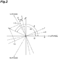
- the rotating coordinate system includes a ⁇ -coordinate system illustrated in FIG. 2 .
- the origin of the ⁇ -coordinate system is located on the rotational axis of the mover of the electric motor 3.
- the ⁇ -coordinate system is a coordinate system that rotates in synchronization with the frequency of the output voltage.
- the ⁇ -axis coincides with the ⁇ -axis of the ⁇ -coordinate system, which is a fixed coordinate system described later, at the time of startup, for example, and rotates in synchronization with the frequency command in response to startup.
- the ⁇ -axis is a coordinate axis perpendicular to the ⁇ -axis and the rotation center axis of the mover of the electric motor 3.
- Various quantities related to control are calculated based on the ⁇ -coordinate system.
- the inductance storage unit 131 stores the inductance profile.
- the inductance profile is a profile indicating the relationship between the value of the output current and the value of the inductance.
- the inductance profile is set such that the inductance changes in accordance with the value of the output current.
- the inductance profile is set such that at least the inductance corresponding to a first output current value and the inductance corresponding to a second output current value are different from each other.
- the inductance storage unit 131 may store a three-dimensional inductance profile that changes in accordance with two values of the ⁇ -axis current iy and the ⁇ -axis current i ⁇ for each of the ⁇ -axis inductance L ⁇ and the ⁇ -axis inductance L ⁇ .
- the inductance storage unit 131 may store the inductance profile as a function or may store the inductance profile as point sequence data.
- the control circuitry 100 may be configured to reduce the correction of the phase of the voltage command by the error calculation unit 115 when the rotational speed of the electric motor 3 is a second speed that is higher than a first speed, compared to when the rotational speed of the second unit is the first speed.
- the control circuitry 100 further includes a gain storage unit 141 and a gain calculation unit 142.
- the gain storage unit 141 stores a gain profile in which the gain when the rotational speed of the electric motor 3 is the first speed is smaller than the gain when the rotational speed of the electric motor 3 is the second speed that is higher than the first speed.
- the first speed and the second speed may be any speed as long as there is a relationship that the second speed is higher than the first speed.
- the command correction unit 116 may correct the phase of the voltage command by a correction amount obtained by multiplying the gain calculated by the gain calculation unit 142 by a correction amount based on the phase error.
- the control circuitry 100 may further include a gain generation unit (not illustrated) that is configured to generate a gain profile based on a user input or the like and to store the generated gain profile in the gain storage unit 141.
- the gain generation unit may be configured to automatically generate a gain profile based on the accumulated data.
- FIG. 4 is a block diagram illustrating a hardware configuration of the control circuitry 100.
- the control circuitry 100 includes at least one a processor 191, a memory 192, storage 193, and switching control circuitry 194.
- the storage 193 includes a computerreadable storage medium, such as a hard disk.
- the storage medium may be a removable medium such as a nonvolatile semiconductor memory, a magnetic disk, or an optical disk.
- the display device 200 and the input device 300 function as user interfaces of the power conversion device 1.
- the display device 200 includes, for example, a liquid crystal monitor, and is used to display information to the user.
- the input device 300 is, for example, a keypad or the like, and acquires input information by the user.
- the display device 200 and the input device 300 may be integrated like a so-called touch panel.
- the display device 200 and the input device 300 may be provided in an external device connected to the power conversion device 1 or may be incorporated in the power conversion device 1.
- the voltage command calculation unit 122 adds or subtracts a voltage drop, a speed electromotive force, or the like to or from the induced voltage target value calculated in the step S01 to generate the voltage command.
- the voltage command calculation unit 122 calculates the ⁇ -axis voltage command Vy and the ⁇ -axis voltage command V ⁇ based on the ⁇ -axis current iy and the ⁇ -axis current i ⁇ calculated by the current acquisition unit 114 in the previous control cycle, the winding resistance of the electric motor 3, the rotational speed of the electric motor 3 derived based on the frequency command, the estimated value of the inductance of the electric motor 3 derived by the step S02, and the induced voltage target value.
- the PWM control unit 117 starts to control the power conversion circuitry 10 so that the driving power follows the voltage command having phase is corrected in the step S05 (the voltage command after correction).
- the step S02 inductance estimation
- the step S02 may be performed before the step S01 (induced voltage target value calculation).
- the step S02 may be executed after the step S07 (current information acquisition).
- the step 03 voltage command calculation
- the voltage command calculation unit 122 generates the voltage command based on the estimated value of the inductance derived by the inductance estimation unit 132 in the previous control cycle.
- a voltage command calculation unit 155 is configured to calculate the voltage command based on the correction voltage calculated by the current control unit 154. For example, based on the output current from the power conversion circuitry 10 to the electric motor 3, the rotational speed of the electric motor 3, and the estimated value of the inductance of the electric motor 3, the voltage command calculation unit 155 calculates a voltage vector obtained by performing a decoupling compensation on an induced voltage vector in which the ⁇ -axis component is 0 and the ⁇ -axis component is the product of the rotational speed of the electric motor 3 and a speed electromotive force constant, and calculates a voltage command vector by adding a correction voltage vector to the voltage vector.
- V ⁇ E ⁇ ⁇ ⁇ ⁇ L ⁇ ⁇ i ⁇
- V ⁇ E ⁇ + ⁇ L ⁇ ⁇ i ⁇ + ⁇
- the speed estimation unit 152 is configured to estimate the rotational speed of the electric motor 3 based on the phase error or the like calculated by the error calculation unit 115.
- the speed control unit 153 calculates the current command using a deviation between the rotational speed target value of the electric motor 3 and the rotational speed of the electric motor 3 estimated by the speed estimation unit 152 as the speed deviation.
- the current control unit 154 calculates the correction voltage based on the deviation between the output current target value and the output current calculated by the current acquisition unit 114 in the previous control cycle (the current deviation).
- the inductance estimation unit 132 derives the estimated value of the inductance.
- the voltage command calculation unit 155 calculates the voltage command based on the correction voltage calculated in the step S12. For example, the voltage command calculation unit 155 calculates the voltage command based on the output current calculated by the current acquisition unit 114 in the previous control cycle, the rotational speed of the electric motor 3, the correction voltage calculated by the step S12, and the estimated value of the inductance of the electric motor 3 derived by the step S13.
- the error calculation unit 115 calculates the phase error of the voltage command based on the voltage command before correction calculated in the step S14, the output current calculated in the step S18, and the estimated value of the inductance derived in the step S13.
- the rotational speed of the electric motor 3 is estimated based on the phase error calculated in the step S19.
- the output current calculated in the step S18 is also used in the step S13 in the next control cycle.
- the estimation result of the phase error in the step S19 is used in the step S16 in the next control cycle.
- the estimation result of the rotational speed of the electric motor 3 in the step S21 is used in the step S11 in the next control cycle.
- the step S13 inductance estimation
- the step S12 correction voltage calculation
- the step S13 may be executed after the step S18 (current information acquisition).
- the step S14 voltage command calculation
- the voltage command calculation unit 155 calculates the voltage command based on the correction voltage.
- the error calculation unit 115 may calculate the induced voltage vector based on the voltage command, the output current from the power conversion circuitry 10 to the electric motor 3, and the estimated value of the inductance, and calculate the phase error based on the phase of the induced voltage vector. In this case, the phase error can be calculated more appropriately.
- the power conversion device 1 may further include: the inductance storage unit 131 that stores the inductance profile in which inductance changes in accordance with a value of output current; and the inductance estimation unit 132 that derives the estimated value of inductance based on the value of output current from the power conversion circuitry 10 to the electric motor 3 and the inductance profile, in which the command generation unit 111 may calculate the voltage command based on the estimated value of inductance derived by the inductance estimation unit 132, and the error calculation unit 115 may calculate the phase error based on the estimated value of inductance derived by the inductance estimation unit 132.
- an inductance profile in which the inductance changes according to the value of the output current can be stored in advance, and the estimated value of the inductance can be derived based on the inductance profile. Accordingly, an error increase in the estimated value of the inductance due to a change in the value of the output current is prevented. Therefore, it is more effective in improving the robustness of the control of the electric motor 3 with respect to the inductance change of the power supply destination including the electric motor 3.
- the power conversion device 1 may further include the profile generation unit 134 that generates the inductance profile based on the user input specifying at least two points of the inductance profile. In this case, by the user's setting the inductance profile suitable for the actual electric motor, expansion of the error of the estimated value of the inductance can be more reliably prevented.
- the command correction unit 116 may correct the phase of the voltage command based on the integral value of the phase error. In this case, the phase of the electric motor 3 can be corrected more quickly.
- the power conversion device 1 may further include: the gain storage unit 141 that stores a gain profile in which a gain when an operation speed of the electric motor 3 is a second speed higher than a first speed is smaller than a gain when the operation speed is the first speed; and the gain calculation unit 142 that calculates a gain based on the operation speed of the electric motor 3 and the gain profile, and the command correction unit 116 may correct the phase of the voltage command by a correction amount obtained by multiplying the correction amount based on the phase error by the gain calculated by the gain calculation unit 142.
- voltage amplitude As the operating speed of the electric motor 3 increases, there is less room for increasing the absolute value of the voltage command vector (hereinafter referred to as "voltage amplitude").
- the electric motor 3 may be a synchronous motor having saliency, and the command generation unit 111 may calculate a voltage command for generating the driving power corresponding to the synchronous motor having saliency.
- a change in inductance corresponding to a change in the output current is larger than that in a synchronous motor having no saliency. For this reason, when the electric motor 3 is a synchronous motor having saliency, it is more beneficial to improve the robustness of the control of the electric motor 3 with respect to the inductance change.
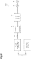
- FIG. 8 is a schematic diagram illustrating a system including the power conversion device 1.
- a system PS1 illustrated in FIG. 8 is a system for pumping out water in a hole excavated by resource search, civil engineering work, or the like, and includes the power conversion device 1, the electric motor 3, a filter 4, a step-up transformer 5, and an electric submersible pump 6.
- the filter 4 include an LC filter having a coil 41 and a capacitor 42. Since the filter 4 is electrically interposed between the power conversion circuitry 10 and the electric motor 3, the above-described the current sensor 14 detects the output current from the power conversion circuitry 10 to the filter 4.
- the step-up transformer 5 is interposed between the filter 4 and the electric motor 3. Being interposed between the filter 4 and the electric motor 3 means being electrically interposed between the filter 4 and the electric motor 3.
- the step-up transformer 5 boosts the output of the filter 4 and supplies the boosted output to the electric motor 3.
- Boosting the output means raising the output voltage at the output.
- the electric motor 3 has an input portion (the primary side) connected to the filter 4 and an output portion (the secondary side) connected to the electric motor 3, boosts an output that is input from the filter 4 to the input portion, and outputs the boosted output from the output portion to the electric motor 3.
- the step-up transformer 5 may be a Y-Y transformer in which both the primary side and the secondary side are star-connected, a ⁇ - ⁇ transformer in which both the primary side and the secondary side are delta-connected, a Y- ⁇ transformer in which the primary side is star-connected and the secondary side is delta-connected, or a ⁇ -Y transformer in which the primary side is delta-connected and the secondary side is star-connected.
- the step-up transformer 5 compensates for a voltage drop in an electric path (for example, a cable or the like) from the step-up transformer 5 to the electric motor 3 by boosting the output of the filter 4.
- the electric path length from the step-up transformer 5 to the electric motor 3 is, for example, 1 to 10 km.
- the electric submersible pump 6 is driven by the electric motor 3.
- the electric submersible pump 6 is arranged in a hole excavated by resource search, civil engineering work, or the like, and discharges water accumulated in the hole to the outside of the hole by driving force imparted from the electric motor 3.
- control circuitry 100 may further include a compensation value storage unit 161 and a current correction unit 162, as illustrated in FIG. 9 .
- the compensation value storage unit 161 is configured to store a phase compensation value that compensates for a phase change of the current in at least the step-up transformer 5 (a difference in phase between the current in the primary side and the current in the secondary side).
- the phase compensation value may include a first phase compensation value that compensates for a phase change of the voltage in the step-up transformer 5.
- the difference in phase between the current obtained by subtracting the excitation current from the current of the primary side and the current of the secondary side is equal to the difference in phase between the voltage of the primary side and the voltage of the secondary side. Therefore, compensating for the phase change of the voltage in the step-up transformer 5 corresponds to compensating for at least a part of the phase change of the current in the step-up transformer 5.
- the compensation value storage unit 161 may further store the second phase compensation value that compensates for, at least, a phase change of the current in the filter 4.
- the phase compensation value and the second phase compensation value are derived in advance by an actual machine test, simulation, or the like.
- the phase compensation value is determined in accordance with the phase differences of the voltage and current generated between the primary side and the secondary side of the step-up transformer 5, and the second phase compensation value is determined in accordance with the magnitude of the excitation current of the primary side of the step-up transformer 5, the fundamental wave component of the current to be supplied to the capacitor of the filter 4, and the like.
- the current correction unit 162 may be configured to correct the magnitude of the output current (for example, multiply the inverse ratio of the transformation ratio) based on the transformation ratio in the step-up transformer 5 (the magnification of the secondary side voltage with respect to the primary side voltage).
- the current correction unit 162 may correct the output current vector calculated by the rotational coordinate conversion by correcting the angle for the rotational coordinate conversion based on the phase compensation value and the second phase compensation value before the current acquisition unit 114 performs the rotational coordinate conversion.
- the voltage command calculation unit 122 may calculate the voltage command based on the frequency command, the output current from the power conversion circuitry 10 to the electric motor 3 (the output current detected by the current sensor 14), the estimated value of the inductance, and the phase compensation value. For example, the voltage command calculation unit 122 calculates the voltage command based on the frequency command, the output current corrected by the current correction unit 162 based on the phase compensation value, and the estimated value of the inductance.
- the calculation method of the voltage command by the voltage command calculation unit 122 is the same as the above-described method except that it is based on the output current corrected by the current correction unit 162 based on the phase compensation value.
- the error calculation unit 115 may calculate the phase error based on the voltage command, the output current from the power conversion circuitry 10 to the electric motor 3 (the output current detected by the current sensor 14), the estimated value of the inductance, and the phase compensation value. For example, the error calculation unit 115 calculates the phase error based on the frequency command, the output current corrected by the current correction unit 162 based on the phase compensation value, and the estimated value of the inductance.
- the calculation method of the phase error by the error calculation unit 115 is the same as the above-described method except that it is based on the output current corrected by the current correction unit 162 based on the phase compensation value.
- the phase of the secondary side voltage leads the phase of the primary side voltage by 30°
- the phase of the secondary side current leads the phase of the primary side current by 30°.
- the phase compensation value is 30°.
- the current correction unit 162 adds 30° to the phase of the output current detected by the current sensor 14.
- the command correction unit 116 adds the phase error calculated by the error calculation unit 115 to the phase of the voltage command generated by the voltage command calculation unit 122, and subtracts 30° from the phase.
- the command correction unit 116 may be configured to correct the magnitude of the voltage command based on the transformation ratio in the step-up transformer 5 (for example, multiply the inverse ratio of the transformation ratio).
- the specifications of the step-up transformer 5, such as the phase shift between the primary voltage and the secondary voltage, the accurate transformation ratio including the tap variation, and the excitation current, may be unknown.
- the motor constants indicated in advance as the design value of the motor are used for a winding resistance R, the ⁇ -axis inductance Ly, and the ⁇ -axis inductance L ⁇ of the electric motor 3, and a voltage lower than the rated voltage of the inverter is set for an induced voltage target value E.
- the voltage command is determined by expressions (1) and (2), and the second phase compensation value for compensating for a phase change caused by the filter 4 is set in the compensation value storage unit 161.
- FIG. 10 is a flowchart illustrating an example power conversion procedure when the control circuitry 100 further includes the compensation value storage unit 161 and the current correction unit 162. As illustrated in FIG. 10 , the control circuitry 100 executes steps S31, S32, S33, S34, S35, S36, S37, S38, and S39. In the step S31, similarly to the step S01, the induced voltage calculation unit 121 calculates the induced voltage target value corresponding to the frequency command in accordance with a predetermined command profile.
- the inductance estimation unit 132 derives an estimated value of inductance based on the value of output current acquired by the current acquisition unit 114 in the previous control cycle and the inductance profile stored in the inductance storage unit 131.
- the voltage command calculation unit 122 calculates the ⁇ -axis voltage command Vy and the ⁇ -axis voltage command V ⁇ based on the output current corrected by the current correction unit 162 in the previous control cycle, the winding resistance of the electric motor 3, the rotational speed of the electric motor 3 derived based on the frequency command, the estimated value of the inductance of the electric motor 3, and the induced voltage target value.
- the voltage calculation unit 112 calculates the absolute value of the voltage command
- the phase calculation unit 113 calculates the phase of the voltage command in the fixed coordinate system.
- the PWM control unit 117 starts to control the power conversion circuitry 10 so as to control the driving power to follow the voltage command having the phase and the magnitude corrected in the step S34 (the voltage command after correction).
- the current acquisition unit 114 acquires, from the current sensor 14, the current information output from the power conversion circuitry 10 to the filter 4 in accordance with the voltage command after correction, and performs three-phase to two-phase conversion and rotational coordinate conversion on the acquired current information to calculate the ⁇ -axis current iy and the ⁇ -axis current i ⁇ .
- the current correction unit 162 corrects the output current calculated in the step S36 based on the phase compensation value, for example, by rotation conversion.
- the error calculation unit 115 calculates the voltage command based on the frequency command, the output current corrected by the current correction unit 162 based on the phase compensation value, and the estimated value of the inductance. This completes one cycle of the control procedure.
- the control circuitry 100 repeats the above procedure at a predetermined control cycle.
- the procedure in which the current acquisition unit 114 calculates the output current vector and then the current correction unit 162 corrects the phase of the output current vector has been exemplified, but the procedure is not limited thereto.
- the current correction unit 162 may correct the output current vector calculated by the rotational coordinate conversion by correcting the angle for the rotational coordinate conversion before the current acquisition unit 114 performs the rotational coordinate conversion.
- the power conversion device 1 may further include a tuning control unit 163, a tuning unit 164, and a parameter storage unit 165 instead of the inductance estimation unit 132.
- the tuning control unit 163 is configured to apply a tuning voltage from the power conversion circuitry 10 to the electric motor 3 in a state in which the power conversion circuitry 10 is connected to the electric motor 3 without intervening the filter 4 and the step-up transformer 5.
- the tuning unit 164 is configured to derive at least one control parameter including at least an estimated value of the inductance based on the tuning voltage and a tuning current flowing between the power conversion circuitry 10 and the electric motor 3 in response to the application of the tuning voltage.
- the parameter storage unit 165 stores the control parameter derived by the tuning unit 164.
- the estimated value of the inductance derived by the tuning unit 164 includes the inductance of the electric path from the power conversion circuitry 10 to the electric motor 3 and the inductance of the electric motor 3 itself.
- the at least one control parameter may further include an estimated value of a resistance of the electric motor 3 in addition to the estimated value of the inductance.
- the estimated value of the resistance of the electric motor 3 includes the resistance of the electric path from the power conversion circuitry 10 to the electric motor 3 and the resistance of the winding itself of the electric motor 3.
- the voltage command calculation unit 122 may calculate the voltage command based on the frequency command, the output current corrected by the current correction unit 162, and at least one control parameter.
- the error calculation unit 115 may calculate the phase error based on the voltage command, the output current corrected by the current correction unit 162, and at least one control parameter.
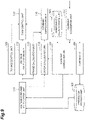
- the control circuitry 100 When it is determined that the tuning period has not elapsed in the step S43, the control circuitry 100 returns the processing to the step S41. When it is determined that the tuning period has elapsed in the step S43, the control circuitry 100 executes a step S44.
- the tuning unit 164 derives at least one control parameter based on the tuning current flowing between the power conversion circuitry 10 and the electric motor 3 in response to the application of the tuning voltage and the tuning voltage, and stores the derived control parameter in the parameter storage unit 165. This completes the procedure for deriving the control parameters.
Landscapes
- Engineering & Computer Science (AREA)
- Power Engineering (AREA)
- Control Of Ac Motors In General (AREA)
Abstract
Description
- The present disclosure relates to a power conversion device, a power conversion method, and a system.
-
Patent Document 1 discloses a control method for controlling an armature rotating magnetic field and a rotor speed of an IPM motor by using an estimated signal of a rotor magnetic pole position and a rotor speed estimated signal obtained by calculation from an internal signal of a control device of the IPM motor. - [Patent Document 1]
Japanese Patent No. 4228651 - The present disclosure provides a power conversion device, a power conversion method, and a system that are effective in improving robustness of control of an electric motor with respect to a change in inductance of a power supply destination including the electric motor.
- A power conversion device according to an aspect of the present disclosure includes: a power conversion unit configured to generate a driving power of an electric motor; a command generation unit that calculates a voltage command based on a frequency command, an output current from the power conversion unit to the electric motor, and an estimated value of an inductance of the electric motor; an error calculation unit that calculates a phase error based on the voltage command, the output current from the power conversion unit to the electric motor, and the estimated value of the inductance; a command correction unit that corrects a phase of the voltage command based on the phase error; and a control unit that controls the power conversion unit to control the driving power to follow the voltage command having the phase corrected by the command correction unit.
- A power conversion method according to another aspect of the present disclosure includes: calculating a voltage command based on a frequency command, an output current from the power conversion unit to the electric motor, and an estimated value of an inductance of the electric motor; calculating a phase error based on a voltage command, the output current from the power conversion unit to the electric motor, and the estimated value of the inductance; correcting a phase of the voltage command based on the phase error; and controlling the power conversion unit to control the driving power to follow the voltage command having a corrected phase.
- A system according to still another aspect of the present disclosure includes: the above-described power conversion device; the electric motor; a filter that reduces a noise component included in an output of a power conversion unit, and a step-up transformer that boosts the output of the power conversion unit and supplies the boosted output to the electric motor.
- According to the present disclosure, it is possible to provide a power conversion device, a power conversion method, and a system that are effective in improving robustness of control of an electric motor with respect to a change in inductance of a power supply destination including the electric motor.
-
-
FIG. 1 is a block diagram illustrating an example configuration of a power conversion device. -
FIG. 2 is a schematic diagram illustrating an example fixed coordinate system and an example rotating coordinate system. -
FIG. 3 is a graph illustrating a gain profile. -
FIG. 4 is a block diagram illustrating an example hardware configuration of a control circuitry. -
FIG. 5 is a flowchart illustrating an example power conversion procedure. -
FIG. 6 is a block diagram illustrating a modification of the control circuitry. -
FIG. 7 is a flow chart illustrating a modification of a power conversion procedure. -
FIG. 8 is a schematic diagram illustrating an example system including the power conversion device. -
FIG. 9 is a schematic diagram illustrating a modification of the control circuitry. -
FIG. 10 is a flowchart illustrating a modification of the power conversion procedure. -
FIG. 11 is a flowchart illustrating an example procedure for deriving a control parameter. - Hereinafter, an embodiment will be described in detail with reference to the drawings. In the description, the same elements or elements having the same functions are denoted by the same reference numerals, and redundant description will be omitted.
- A
power conversion device 1 illustrated inFIG. 1 is a device that performs power conversion between apower supply 2 and anelectric motor 3. Thepower supply 2 is, for example, a three-phase alternatingcurrent (AC) power supply. Specific examples of thepower supply 2 include a three-phase AC power system, a three-phase AC generator, and an uninterruptible power supply. - The
electric motor 3 is a synchronous motor that operates by supply of AC power (for example, three-phase AC power). Theelectric motor 3 may be a synchronous motor having saliency. Having saliency means that an inductance of theelectric motor 3 with respect to a current in the magnetic pole direction of a mover is different from an inductance of theelectric motor 3 with respect to the current in a direction perpendicular to the magnetic pole direction. Specific examples of the synchronous motor having saliency include a permanent magnet assistance (PMA) motor, an interior permanent magnet (IPM) motor, and a synchronous reluctance motor. Theelectric motor 3 may be a synchronous motor having no saliency. Specific examples of the synchronous motor having no saliency include a surface permanent magnet (SPM) motor. - The
electric motor 3 may be a fixed coil type in which a coil is provided in a fixed element or may be a movable coil type in which a coil is provided in a movable element. Theelectric motor 3 may be a rotary type or a linear type. Hereinafter, a case where theelectric motor 3 is a rotary type will be described, and the operation speed of theelectric motor 3 will be referred to as "rotational speed". "Rotational speed" is the rotational speed of theelectric motor 3. - The
power conversion device 1 includespower conversion circuitry 10 andcontrol circuitry 100. The power conversion circuitry 10 (a power conversion unit) performs power conversion between thepower supply 2 and theelectric motor 3 to generate AC power for driving theelectric motor 3. For example, thepower conversion circuitry 10 converts AC power from the power supply 2 (hereinafter referred to as "source power") into AC power for driving the electric motor 3 (hereinafter referred to as "driving power"), and supplies the converted AC power to theelectric motor 3. As an example, thepower conversion circuitry 10 includesrectifier circuitry 11, asmoothing capacitor 12,inverter circuitry 13, and acurrent sensor 14. Therectifier circuitry 11 is, for example, diode bridge circuitry or PWM converter circuitry, and converts the source power into direct-current (DC) power. Thesmoothing capacitor 12 smoothes the DC power. - The
inverter circuitry 13 performs power conversion between the DC power and the driving power. For example, theinverter circuitry 13 converts DC power into driving power and supplies the driving power to theelectric motor 3 in a power running state, and converts electric power generated by theelectric motor 3 into DC power in a regeneration state. The power running state is a state in which theelectric motor 3 is operated by driving power supplied from theinverter circuitry 13, and the regeneration state is a state in which theelectric motor 3 supplies generated power corresponding to the motion to theinverter circuitry 13. - For example, the
inverter circuitry 13 includes a plurality ofswitching elements 15, and performs the power conversion by switching on and off theswitching elements 15. Theswitching elements 15 are, for example, a power metal oxide semiconductor field effect transistors (MOSFET), insulated gate bipolar transistors (IGBT), or the like, and switch on and off in accordance with a gate drive signal. - The
current sensor 14 detects a current flowing between theinverter circuitry 13 and theelectric motor 3. For example, thecurrent sensor 14 may be configured to detect currents of all phases (U-phase, V-phase, and W-phase) of the three-phase alternating current, or may be configured to detect currents of any two phases of the three-phase alternating current. Since the sum of the currents of the U-phase, the V-phase, and the W-phase is zero as long as the zero-phase current is not generated, the information of the currents of all the phases is obtained even when the currents of two phases are detected. - The configuration of the
power conversion circuitry 10 described above is merely an example. The configuration of thepower conversion circuitry 10 may be modified in any manner as long as the driving power of theelectric motor 3 can be generated. For example, therectifier circuitry 11 may be thyristor converter circuitry or matrix converter circuitry that converts AC power to DC power. Thepower conversion circuitry 10 may be matrix converter circuitry that performs bi-directional power conversion between source power and driving power without going through DC conversion. When the source power is DC power, thepower conversion circuitry 10 need not include therectifier circuitry 11. - The
control circuitry 100 is configured to execute: calculating a voltage command based on a frequency command, an output current from thepower conversion circuitry 10 to theelectric motor 3, and an estimated value of an inductance of theelectric motor 3; calculating a phase error based on the voltage command, the output current from thepower conversion circuitry 10 to theelectric motor 3, and the estimated value the inductance; correcting a phase of the voltage command based on the phase error; and controlling thepower conversion circuitry 10 to control the driving power to follow the voltage command having the corrected phase. - For example, the
control circuitry 100 includes acommand generation unit 111, avoltage calculation unit 112, aphase calculation unit 113, acurrent acquisition unit 114, anerror calculation unit 115, acommand correction unit 116, and aPWM control unit 117 as functional configurations (hereinafter referred to as a "functional block"). Since each functional block is a component of thecontrol circuitry 100, the processing executed by each functional block corresponds to the processing executed by thecontrol circuitry 100. - The
command generation unit 111 is configured to calculate the voltage command based on the frequency command, the output current from thepower conversion circuitry 10 to theelectric motor 3, and the estimated value of the inductance of theelectric motor 3. The frequency command is a command for determining a target value of a frequency of the driving power. The frequency command may be the target value itself of the frequency of the driving power, or may be a numerical value indirectly determining the target value. For example, the frequency command may be a target value of a rotational speed (a synchronization speed) of theelectric motor 3. The estimated value means a value that is not based on a real-time actual measurement result. The estimated value may be a design value that is not based on actual measurement, or may be a value calculated by simulation. The estimated value may be a value actually measured in advance. The voltage command is, for example, a target value of a voltage output from thepower conversion circuitry 10 to theelectric motor 3. - For example, the
command generation unit 111 includes an inducedvoltage calculation unit 121 and a voltagecommand calculation unit 122 as more subdivided functional blocks. The inducedvoltage calculation unit 121 is configured to calculate an induced voltage corresponding to the frequency command (hereinafter referred to as an "induced voltage target value") in accordance with a predetermined command profile. For example, the command profile is predetermined so that the induced voltage target value changes by a change amount directly proportional to a change amount of the frequency command. The command profile may be defined such that the induced voltage target value is constant when the frequency command is equal to or greater than a predetermined upper limit value. - The voltage
command calculation unit 122 is configured to calculate a voltage command based on an equivalent circuit of theelectric motor 3 using the induced voltage target value calculated by the inducedvoltage calculation unit 121. For example, the voltagecommand calculation unit 122 calculates a voltage command vector in a coordinate system rotating in synchronization with the frequency command (hereinafter referred to as a "rotating coordinate system"). The rotating coordinate system rotates with respect to a coordinate system fixed to the fixed element (a stator) of the electric motor 3 (hereinafter referred to as a "fixed coordinate system"). - A specific example of the fixed coordinate system is an αβ-coordinate system. The origin of the αβ-coordinate system is located on the rotational axis of the mover of the
electric motor 3. The α-axis is a coordinate axis whose direction coincides with the direction of a magnetomotive force generated by a current flowing in any of the three-phase winding of the fixed element, for example. The β-axis is a coordinate axis perpendicular to the α-axis and the rotation center axis of the mover of theelectric motor 3. - Specific examples of the rotating coordinate system includes a γδ-coordinate system illustrated in
FIG. 2 . The origin of the γδ-coordinate system is located on the rotational axis of the mover of theelectric motor 3. The γδ-coordinate system is a coordinate system that rotates in synchronization with the frequency of the output voltage. The γ-axis coincides with the α-axis of the αβ-coordinate system, which is a fixed coordinate system described later, at the time of startup, for example, and rotates in synchronization with the frequency command in response to startup. The δ-axis is a coordinate axis perpendicular to the γ-axis and the rotation center axis of the mover of theelectric motor 3. Various quantities related to control are calculated based on the γδ-coordinate system. - On the other hand, there is a dq-coordinate system which rotates with being fixed to the mover (a rotor) of the
electric motor 3. The origin of the dq-coordinate system is located on the rotational axis of the mover of theelectric motor 3. The d-axis is a coordinate axis in which the magnetic pole direction of the mover of the electric motor 3 (the direction from the S-pole to the N-pole in a permanent magnet) is the positive direction. The q-axis is a coordinate system perpendicular to the d-axis and the rotation center axis of the mover of theelectric motor 3. - For example, the voltage
command calculation unit 122 calculates a γ-axis voltage command Vy which is a γ-axis component of the voltage command vector V, and a δ-axis voltage command Vδ which is a δ-axis component of the voltage command vector V. The voltagecommand calculation unit 122 calculates the γ-axis voltage command Vy and the δ-axis voltage command Vδ by applying a compensation of a winding voltage drop based on the output current from thepower conversion circuitry 10 to theelectric motor 3 and the winding resistance of theelectric motor 3, and a decoupling compensation based on the rotational speed of theelectric motor 3 and the estimated value of the inductance of theelectric motor 3 to the induced voltage target value. - As an example, the voltage
command calculation unit 122 calculates the γ-axis voltage command Vy and the δ-axis voltage command Vδ by the following expressions.

- In expressions (1) and (2), iy is a γ-axis component of an output current vector (hereinafter referred to as a "y-axis current"). iδ is a δ-axis component of the output current vector (hereinafter referred to as a "δ-axis current"). R is a winding resistance of the
electric motor 3. ω is a rotational speed of the mover and is derived based on the frequency command. Ly is an inductance of theelectric motor 3 with respect to the γ-axis current (hereinafter referred to as "y-axis inductance"). Lδ is an inductance of theelectric motor 3 with respect to the δ-axis current (hereinafter referred to as "δ-axis inductance"). E is the induced voltage target value and is determined based on the frequency command using, for example, a V/f pattern that is set. - The voltage
command calculation unit 122 uses a γ-axis current iy and a δ-axis current iδ calculated by thecurrent acquisition unit 114 described later as the γ-axis current iy and the δ-axis current iδ for calculating the γ-axis voltage command Vy and the δ-axis voltage command Vδ. The voltagecommand calculation unit 122 may use a value calculated by thecurrent acquisition unit 114 as one of the γ-axis current iy and the δ-axis current iδ for calculating the γ-axis voltage command Vy and the δ-axis voltage command Vδ may be a value calculated by thecurrent acquisition unit 114, and may use a predetermined command value as the other of the γ-axis current iy and the δ-axis current iδ. - For example, the voltage
command calculation unit 122 may use the value calculated by thecurrent acquisition unit 114 as the δ-axis current iδ for calculating the γ-axis voltage command Vy and the δ-axis voltage command Vδ and may use a predetermined command value as the γ-axis current iy. In this case, thecommand generation unit 111 may further include a currentcommand generation unit 123. The currentcommand generation unit 123 is configured to generate a command value of the γ-axis current iy. The currentcommand generation unit 123 may generate a negative γ-axis current iy as a command for a reluctance power (a power due to saliency). The currentcommand generation unit 123 may generate the γ-axis current iy based on the frequency command. For example, the currentcommand generation unit 123 may increase the absolute value of the γ-axis current iy as the frequency command increases. Increasing the absolute value of the γ-axis current iy in accordance with an increase in the frequency command includes increasing the absolute values of the γ-axis current iy in accordance with an increase in the frequency command in a predetermined range of the frequency command and making the absolute values of the γ-axis current iy constant in other ranges. - Returning to
FIG. 1 , thevoltage calculation unit 112 is configured to calculate the absolute value of the voltage command generated by thecommand generation unit 111. For example, thevoltage calculation unit 112 calculates the square root of the sum of squares of the γ-axis voltage command Vy and the δ-axis voltage command Vδ calculated by the voltagecommand calculation unit 122 as the absolute value of the voltage command vector V. - The
phase calculation unit 113 is configured to calculate the phase of the voltage command in the fixed coordinate system. For example, thephase calculation unit 113 calculates the phase angle of the voltage command vector V with respect to the α-axis of the αβ-coordinate system. For example, thephase calculation unit 113 calculates the phase angle θf of the γδ-coordinate system with respect to the αβ-coordinate system (for example, a phase angle of the γ-axis with respect to the α-axis) based on the frequency command, calculates the phase angle θv of the voltage command vector V in the γδ-coordinate system (a phase angle of the voltage command vector V with respect to the γ-axis) based on the γ-axis voltage command Vy and the δ-axis voltage command Vδ, and sums a phase angle θf and a phase angle θv to calculate a phase angle θ of the voltage command vector V with respect to the α-axis (seeFIG. 2 ). - The
current acquisition unit 114 is configured to acquire the current information from thecurrent sensor 14. For example, thecurrent acquisition unit 114 performs three-phase to two-phase conversion and rotational coordinate conversion on the current information acquired from thecurrent sensor 14 to calculate the γ-axis current iy and the δ-axis current iδ. This rotational coordinate conversion requires the phase of the rotating coordinate system with respect to the fixed coordinate system. For example, thecurrent acquisition unit 114 uses the phase angle θf calculated by thephase calculation unit 113 for the rotational coordinate conversion. - The
error calculation unit 115 is configured to calculate the phase error of the voltage command based on the voltage command, the output current from thepower conversion circuitry 10 to theelectric motor 3, and the estimated value of the inductance. The phase error is an angular error between the γδ-coordinate system and the dq-coordinate system. - For example, the
error calculation unit 115 calculates an induced voltage vector based on the voltage command vector, the output current vector from thepower conversion circuitry 10 to theelectric motor 3, the winding resistance of theelectric motor 3, and the estimated value of the inductance, and calculates the phase error based on the phase of the induced voltage vector. For example, theerror calculation unit 115 calculates a phase angle of the induced voltage vector in the γδ-coordinate system with respect to the δ-axis as a phase error. As an example, theerror calculation unit 115 calculates the phase error by the following expressions, assuming that the rotational direction of the γδ-coordinate system with respect to the αβ-coordinate system is a positive direction.


- In expressions (3), (4), and (5), Δθ is the phase error, εd is the γ-axis component of the induced voltage vector, and εq is the δ-axis component of the induced voltage vector.
- As exemplified above, the principle that the phase angle of the induced voltage vector with respect to the δ-axis in the γδ-coordinate system can be used as the phase error is described as follows. When the γ-axis coincides with the d-axis facing the positive direction of the magnetic pole direction of the mover of the
electric motor 3, the induced voltage is originally generated only in the δ-axis direction. However, when the γ-axis does not coincide with the d-axis, the induced voltage vector is inclined with respect to the δ-axis by the error. Therefore, it can be said that the phase angle of the induced voltage vector with respect to the δ-axis indicates the phase error. The phase error is mainly generated by an error of the estimated value of the inductance. In particular, in a synchronous reluctance motor, since the fluctuation of the inductance in accordance with the value of the output current is large compared to a permanent magnet type electric motor, the error of the estimated value of the inductance is likely to be large. - The
current acquisition unit 114 may use a phase angle obtained by adding a phase error Δθ to the phase angle θf calculated by thephase calculation unit 113 in the rotational coordinate conversion. - The
command correction unit 116 is configured to correct the phase of the voltage command based on the phase error calculated by theerror calculation unit 115. For example, thecommand correction unit 116 may correct the phase of the voltage command by adding a correction amount based on the phase error calculated by theerror calculation unit 115 to the phase calculated by the phase calculation unit 113 (hereinafter referred to as a "phase before correction"). Hereinafter, the phase of the corrected voltage command is referred to as a "phase after correction". Thecommand correction unit 116 may calculate the correction amount (hereinafter referred to as a "correction amount by proportional operation") by multiplying the phase error calculated by theerror calculation unit 115 by a predetermined proportional gain. - The
command correction unit 116 may correct the phase of the voltage command based on an integral value of the phase error. For example, thecommand correction unit 116 may calculate the correction amount based on an integral value of the phase error calculated by theerror calculation unit 115. Thecommand correction unit 116 may calculate the correction amount (hereinafter referred to as a "correction amount by integral operation") by multiplying the integral value of the phase error calculated by theerror calculation unit 115 by a predetermined proportional gain. Thecommand correction unit 116 may calculate the phase after correction by adding both of the correction amount by proportional operation and the correction amount by integral operation to the phase before correction. - The
command correction unit 116 may calculate the phase after correction by adding, to the phase before correction, a correction amount obtained by applying low-pass filtering to the correction amount calculated as described above. Thecommand correction unit 116 may perform low-pass filtering on the phase after correction to correct the phase of the voltage command. - The PWM control unit 117 (a control unit) is configured to control the
power conversion circuitry 10 to control the driving power to follow the voltage command having the phase corrected by thecommand correction unit 116. Controlling the driving power to follow the voltage command means controlling the voltage in the driving power to follow the voltage command. For example, thePWM control unit 117 switches on and off of the switchingelements 15 of theinverter circuitry 13 so as to output, to theelectric motor 3, a voltage that matches a voltage command determined by the absolute value calculated by thevoltage calculation unit 112 and the phase after correction calculated by thecommand correction unit 116. - The
control circuitry 100 may be configured to change the estimated value of the inductance in response to a value of output current from thepower conversion circuitry 10 to theelectric motor 3. For example, thecontrol circuitry 100 may further include aninductance storage unit 131 and aninductance estimation unit 132. - The
inductance storage unit 131 stores the inductance profile. As described above, the inductance profile is a profile indicating the relationship between the value of the output current and the value of the inductance. The inductance profile is set such that the inductance changes in accordance with the value of the output current. The inductance profile is set such that at least the inductance corresponding to a first output current value and the inductance corresponding to a second output current value are different from each other. - The
inductance storage unit 131 may individually store an inductance profile of a γ-axis inductance Ly and an inductance profile of a δ-axis inductance Lδ. Theinductance storage unit 131 may store an inductance profile that changes in accordance with the value of the γ-axis current iy or the δ-axis current iδ for each of the γ-axis inductance Lγ and the δ-axis inductance Lδ. - Further, the
inductance storage unit 131 may store a three-dimensional inductance profile that changes in accordance with two values of the γ-axis current iy and the δ-axis current iδ for each of the γ-axis inductance Lγ and the δ-axis inductance Lδ. Theinductance storage unit 131 may store the inductance profile as a function or may store the inductance profile as point sequence data. - The
inductance estimation unit 132 is configured to derive the estimated value of inductance based on the value of output current acquired (calculated) by the current acquisition unit 114 (for example, the γ-axis current iy and the δ-axis current iδ) and the inductance profile stored by theinductance storage unit 131. For example, theinductance estimation unit 132 derives the value of the inductance corresponding to the value of the output current in the inductance profile as the estimated value of the inductance. When the inductance profile is point sequence data, theinductance estimation unit 132 may derive the inductance value corresponding to the value of the output current by interpolation of the point sequence data. - When the
control circuitry 100 includes theinductance storage unit 131 and theinductance estimation unit 132, the voltagecommand calculation unit 122 calculates the voltage command based on the estimated value of the inductance derived by theinductance estimation unit 132. Theerror calculation unit 115 calculates the phase error based on the estimated value of the inductance derived by theinductance estimation unit 132. - The
control circuitry 100 may further include aprofile generator 134. Theprofile generator 134 is configured to generate the inductance profile based on a user input specifying at least two points of the inductance profile, and to store the generated inductance profile in theinductance storage unit 131. Each of the at least two points includes a combination of a value of the output current and a value of the inductance profile. The user input is an input by a user of thepower conversion device 1, and is input with, for example, aninput device 300 described later. Theprofile generator 134 may store data in which the output current, the estimated value of the inductance, and the phase error are associated with each other while changing the estimated value of the inductance, and may automatically set the inductance profile so as to reduce the phase error based on the stored data. - The
control circuitry 100 may be configured to reduce the correction of the phase of the voltage command by theerror calculation unit 115 when the rotational speed of theelectric motor 3 is a second speed that is higher than a first speed, compared to when the rotational speed of the second unit is the first speed. For example, thecontrol circuitry 100 further includes again storage unit 141 and again calculation unit 142. Thegain storage unit 141 stores a gain profile in which the gain when the rotational speed of theelectric motor 3 is the first speed is smaller than the gain when the rotational speed of theelectric motor 3 is the second speed that is higher than the first speed. The first speed and the second speed may be any speed as long as there is a relationship that the second speed is higher than the first speed. -
FIG. 3 is a graph illustrating an example of the gain profile. InFIG. 3 , the horizontal axis represents frequency of the driving power. Since the frequency of the driving power is substantially proportional to the rotational speed of theelectric motor 3, it can be said that the horizontal axis represents the rotational speed of theelectric motor 3. The vertical axis represents the magnitude of gain. In theFIG. 3 , the gain is constant when the driving power is equal to or lower than a predetermined a frequency threshold ft. Above the frequency threshold ft, the gain decreases as the frequency increases (i.e., As the rotational speed of theelectric motor 3 increases). - In this profile, the gain when the frequency is higher than the frequency threshold ft (when the rotational speed of the
electric motor 3 is the second speed) is smaller than the gain when the frequency is lower than the frequency threshold ft (when the rotational speed of theelectric motor 3 is the first speed). For example, a gain K2 corresponding to a frequency f2 larger than the frequency threshold ft is smaller than a gain K1 corresponding to a frequency f1 smaller than the frequency threshold ft. Thegain storage unit 141 may store the gain profile as a function or may store the gain profile as point sequence data. - The
gain calculation unit 142 is configured to calculate the gain based on the rotational speed of theelectric motor 3 and the gain profile. Thegain calculation unit 142 may calculate the gain based on the frequency command and the gain profile. Since the rotational speed of theelectric motor 3 is substantially proportional to the frequency command, being based on the frequency command corresponds to being based on the rotational speed of theelectric motor 3. For example, thegain calculation unit 142 calculates a gain corresponding to the frequency command in the gain profile. When the gain profile is point sequence data, thegain calculation unit 142 may calculate the gain corresponding to the frequency command by interpolation of the point sequence data. - When the
control circuitry 100 includes thegain storage unit 141 and thegain calculation unit 142, thecommand correction unit 116 may correct the phase of the voltage command by a correction amount obtained by multiplying the gain calculated by thegain calculation unit 142 by a correction amount based on the phase error. Thecontrol circuitry 100 may further include a gain generation unit (not illustrated) that is configured to generate a gain profile based on a user input or the like and to store the generated gain profile in thegain storage unit 141. The gain generation unit may be configured to automatically generate a gain profile based on the accumulated data. -
FIG. 4 is a block diagram illustrating a hardware configuration of thecontrol circuitry 100. As illustrated inFIG. 4 , thecontrol circuitry 100 includes at least one aprocessor 191, amemory 192,storage 193, and switchingcontrol circuitry 194. Thestorage 193 includes a computerreadable storage medium, such as a hard disk. The storage medium may be a removable medium such as a nonvolatile semiconductor memory, a magnetic disk, or an optical disk. Thestorage 193 stores a program for controlling thecontrol circuitry 100 to execute: calculating the voltage command based on the frequency command, the output current from thepower conversion circuitry 10 to theelectric motor 3, and the estimated value of inductance of theelectric motor 3; calculating the phase error based on the voltage command, the output current, and the estimated value of inductance; correcting the phase of the voltage command based on the phase error; and controlling thepower conversion circuitry 10 to control the driving power to follow the voltage command having the corrected phase. - The
memory 192 temporarily stores the program loaded from thestorage 193 and a calculation result by theprocessor 191. Theprocessor 191 configures the above-described functional blocks by executing the program in cooperation with thememory 192. The switchingcontrol circuitry 194 generates the gate drive signal in response to a command from theprocessor 191, and outputs the gate drive signal to theinverter circuitry 13. An input/output port 195 inputs and outputs electrical signals to and from thecurrent sensor 14, adisplay device 200, and theinput device 300 in accordance with instructions from theprocessor 191. - The
display device 200 and theinput device 300 function as user interfaces of thepower conversion device 1. Thedisplay device 200 includes, for example, a liquid crystal monitor, and is used to display information to the user. Theinput device 300 is, for example, a keypad or the like, and acquires input information by the user. Thedisplay device 200 and theinput device 300 may be integrated like a so-called touch panel. Thedisplay device 200 and theinput device 300 may be provided in an external device connected to thepower conversion device 1 or may be incorporated in thepower conversion device 1. - It should be noted that the
control circuitry 100 is not necessarily limited to one that configures each function by a program. For example, thecontrol circuitry 100 may configure at least a part of functions by a dedicated logic circuit or an application specific integrated circuit (ASIC) in which the dedicated logic circuit is integrated. - Hereinafter, as an example of a power conversion method for generating the driving power of the
electric motor 3 using thepower conversion circuitry 10, a control procedure of thepower conversion circuitry 10 using thecontrol circuitry 100 will be described. The procedure includes: calculating the voltage command based on the frequency command, the output current from thepower conversion circuitry 10 to theelectric motor 3, and the estimated value of the inductance of theelectric motor 3; calculating the phase error based on the voltage command, the output current from thepower conversion circuitry 10 to theelectric motor 3, and the estimated value of the inductance of theelectric motor 3; correcting the phase of the voltage command based on the phase error; and controlling thepower conversion circuitry 10 to control the driving power to follow the voltage command having the corrected phase. - For example, the
control circuitry 100 repeats steps S01 to S08 illustrated inFIG. 5 at a predetermined control cycle. In the step S01, the inducedvoltage calculation unit 121 calculates the induced voltage target value corresponding to the frequency command in accordance with the predetermined command profile. - In the step S02, the
inductance estimation unit 132 derives the estimated value of inductance based on the value of output current acquired (calculated) by thecurrent acquisition unit 114 in the previous control cycle (for example, the γ-axis current iy or the δ-axis current iδ) and the inductance profile stored in theinductance storage unit 131. - In the step S03, the voltage
command calculation unit 122 adds or subtracts a voltage drop, a speed electromotive force, or the like to or from the induced voltage target value calculated in the step S01 to generate the voltage command. For example, the voltagecommand calculation unit 122 calculates the γ-axis voltage command Vy and the δ-axis voltage command Vδ based on the γ-axis current iy and the δ-axis current iδ calculated by thecurrent acquisition unit 114 in the previous control cycle, the winding resistance of theelectric motor 3, the rotational speed of theelectric motor 3 derived based on the frequency command, the estimated value of the inductance of theelectric motor 3 derived by the step S02, and the induced voltage target value. - In the step S04, the
voltage calculation unit 112 calculates the absolute value of the voltage command generated in the step S03, and thephase calculation unit 113 calculates the phase of the voltage command in the fixed coordinate system. For example, thephase calculation unit 113 calculates the phase angle θf of the γδ-coordinate system with respect to the αβ-coordinate system based on the frequency command, calculates the phase angle θv of the voltage command vector V in the γδ-coordinate system based on the γ-axis voltage command Vy and the δ-axis voltage command Vδ, sums the phase angle θf and the phase angle θv, and calculates the phase angle θ of the voltage command vector V with respect to the α-axis. - In the step S05, the
command correction unit 116 corrects the phase of the voltage command based on the phase error Δθ calculated by theerror calculation unit 115 in the previous control cycle. For example, thecommand correction unit 116 corrects the phase of the voltage command by adding a correction amount based on the phase error to the phase calculated in the step S03 (the phase before correction). In the step S05, thegain calculation unit 142 may calculate the gain based on the frequency command and the gain profile, and thecommand correction unit 116 may correct the phase of the voltage command by a correction amount obtained by multiplying the gain calculated by thegain calculation unit 142 by the correction amount based on the phase error. - In the step S06, the
PWM control unit 117 starts to control thepower conversion circuitry 10 so that the driving power follows the voltage command having phase is corrected in the step S05 (the voltage command after correction). - In the step S07, the
current acquisition unit 114 acquires the current information output from thepower conversion circuitry 10 to theelectric motor 3 in accordance with the voltage command after correction from thecurrent sensor 14, and performs three-phase to two-phase conversion and rotational coordinate conversion on the acquired current information to calculate the γ-axis current iγ and the δ-axis current iδ. Thecurrent acquisition unit 114 may use the phase angle θf calculated in the step S04 for the rotational coordinate conversion, or may use a phase angle obtained by adding the phase error Δθ to the phase angle θf calculated in the step S04 for the rotational coordinate conversion. - In the step S08, the
error calculation unit 115 calculates the phase error of the voltage command based on the voltage command calculated in the step S03 (the voltage command before correction), the output current calculated in the step S07 (the γ-axis current iy and the δ-axis current iδ), and the estimated value of the inductance derived in the step S02. The output current acquired (calculated) in the step S07 is also used in the step S02 in the next control cycle. The estimation result of the phase error in the step S08 is used in the step S05 in the next control cycle. - This completes one cycle of the control procedure. In one cycle of the control procedure, the step S02 (inductance estimation) may be performed before the step S01 (induced voltage target value calculation). Further, the step S02 may be executed after the step S07 (current information acquisition). In this case, in the step 03 (voltage command calculation), the voltage
command calculation unit 122 generates the voltage command based on the estimated value of the inductance derived by theinductance estimation unit 132 in the previous control cycle. - The step S08 (phase error calculation) may be executed earlier than the step S05 (phase correction). In this case, in the step S05, the
error calculation unit 115 calculates the phase error based on the voltage command calculated in the previous control cycle and the output current calculated in the previous control cycle. -
FIG. 6 is a block diagram illustrating a modification of the control circuitry.Control circuitry 100A illustrated inFIG. 6 is different from thecontrol circuitry 100 in a configuration for calculating the voltage command based on the frequency command. Thecontrol circuitry 100A is obtained by replacing thecommand generation unit 111 in thecontrol circuitry 100 with acommand generator 151 and adding aspeed estimation unit 152. - The
command generator 151 is configured to calculate the voltage command based on the frequency command, the output current from thepower conversion circuitry 10 to theelectric motor 3, and the estimated value of the inductance of theelectric motor 3. Thecommand generator 151 includes aspeed control unit 153 and acurrent control unit 154. - The
speed control unit 153 calculates a current command based on a deviation between a rotational speed target value of theelectric motor 3 and the rotational speed of the electric motor 3 (hereinafter referred to as a "speed deviation"). For example, thespeed control unit 153 calculates the current command by performing proportional operation, proportional-integral operation, or proportional-integralderivative operation on the speed deviation. The rotational speed target value is, for example, a target value of the rotational speed of a rotating magnetic field generated by the alternating current in accordance with the frequency command. The current command is an output current target value from thepower conversion circuitry 10 to theelectric motor 3. - The
current control unit 154 is configured to calculate a correction voltage based on a deviation between the output current target value and the output current value acquired by the current acquisition unit 114 (hereinafter referred to as a "current deviation"). For example, thespeed control unit 153 calculates the correction voltage by performing proportional operation, proportional-integral operation, or proportional-integral-derivative operation on the current deviation. - A voltage
command calculation unit 155 is configured to calculate the voltage command based on the correction voltage calculated by thecurrent control unit 154. For example, based on the output current from thepower conversion circuitry 10 to theelectric motor 3, the rotational speed of theelectric motor 3, and the estimated value of the inductance of theelectric motor 3, the voltagecommand calculation unit 155 calculates a voltage vector obtained by performing a decoupling compensation on an induced voltage vector in which the γ-axis component is 0 and the δ-axis component is the product of the rotational speed of theelectric motor 3 and a speed electromotive force constant, and calculates a voltage command vector by adding a correction voltage vector to the voltage vector. - The above-described calculation by the voltage
command calculation unit 155 is expressed by, for example, the following expressions.

- In expressions (6) and (7), Φ is the velocity electromotive force coefficient, Ey is the γ-axis component of the correction voltage, and Eδ is the δ-axis component of the correction voltage.
- The
error calculation unit 115 calculates the phase error of the voltage command based on the voltage command vector, the correction voltage vector, the output current vector from thepower conversion circuitry 10 to theelectric motor 3, and the estimated value of the inductance. For example, theerror calculation unit 115 calculates an induced voltage vector for calculating the phase error by the following expressions.

- The
speed estimation unit 152 is configured to estimate the rotational speed of theelectric motor 3 based on the phase error or the like calculated by theerror calculation unit 115. Thespeed control unit 153 calculates the current command using a deviation between the rotational speed target value of theelectric motor 3 and the rotational speed of theelectric motor 3 estimated by thespeed estimation unit 152 as the speed deviation. -
FIG. 7 is a flowchart illustrating the control procedure of thepower conversion circuitry 10 by thecontrol circuitry 100A. Thecontrol circuitry 100A repeats steps S11 to S21 illustrated inFIG. 7 at a predetermined control cycle. In the step S11, thespeed control unit 153 calculates the current command based on a deviation between the rotational speed target value of theelectric motor 3 and the rotational speed of theelectric motor 3 estimated by thespeed estimation unit 152 in the previous control cycle (the speed deviation). - In the step S12, the
current control unit 154 calculates the correction voltage based on the deviation between the output current target value and the output current calculated by thecurrent acquisition unit 114 in the previous control cycle (the current deviation). In the step S13, similarly to the step S02, theinductance estimation unit 132 derives the estimated value of the inductance. - In the step S14, the voltage
command calculation unit 155 calculates the voltage command based on the correction voltage calculated in the step S12. For example, the voltagecommand calculation unit 155 calculates the voltage command based on the output current calculated by thecurrent acquisition unit 114 in the previous control cycle, the rotational speed of theelectric motor 3, the correction voltage calculated by the step S12, and the estimated value of the inductance of theelectric motor 3 derived by the step S13. - In the step S15, similarly to the step S04, the
voltage calculation unit 112 calculates the absolute value of the voltage command, and thephase calculation unit 113 calculates the phase of the voltage command in the fixed coordinate system. In the step S16, similarly to the step S05, thecommand correction unit 116 corrects the phase of the voltage command based on the phase error Δθ calculated by theerror calculation unit 115 in the previous control cycle. In the step S17, similarly to the step S06, thePWM control unit 117 starts to control thepower conversion circuitry 10 so as to control the driving power to follow the voltage command after correction. - In the step S18, similarly to the step S07, the
current acquisition unit 114 acquires, from thecurrent sensor 14, the current information output from thepower conversion circuitry 10 to theelectric motor 3 in accordance with the voltage command after correction, and performs the three-phase to two-phase conversion and the rotational coordinate conversion on the acquired current information to calculate the γ-axis current iy and the δ-axis current iδ. - In the step S19, similarly to the step S08, the
error calculation unit 115 calculates the phase error of the voltage command based on the voltage command before correction calculated in the step S14, the output current calculated in the step S18, and the estimated value of the inductance derived in the step S13. In the step S21, the rotational speed of theelectric motor 3 is estimated based on the phase error calculated in the step S19. - The output current calculated in the step S18 is also used in the step S13 in the next control cycle. The estimation result of the phase error in the step S19 is used in the step S16 in the next control cycle. The estimation result of the rotational speed of the
electric motor 3 in the step S21 is used in the step S11 in the next control cycle. - This completes one cycle of the control procedure. In the control procedure of one cycle, the step S13 (inductance estimation) may be executed before the step S11 (current target value calculation) and S12 (correction voltage calculation). Further, the step S13 may be executed after the step S18 (current information acquisition). In this case, in the step S14 (voltage command calculation), based on the estimated value of the inductance derived by the
inductance estimation unit 132 in the previous control cycle the voltagecommand calculation unit 155 calculates the voltage command based on the correction voltage. - The step S19 (phase error calculation) may be executed before the step S16 (phase correction). In this case, in the step S19, the
error calculation unit 115 calculates the phase error based on the voltage command calculated in the previous control cycle and the output current calculated in the previous control cycle. The step S21 (speed estimation) may be executed before the step S11 (current target value calculation). In this case, the step S21 estimates the rotational speed of theelectric motor 3 based on the phase error calculated in the previous control cycle. - As described in the above modification, the command generator of the control circuitry may be configured to calculate the voltage command based on the frequency command, the output current from the
power conversion circuitry 10 to theelectric motor 3, and the estimated value of the inductance of theelectric motor 3, and the calculation method may be changed as appropriate. - As described above, the
power conversion device 1 includes: thepower conversion circuitry 10 that generates the driving power of theelectric motor 3; thecommand generation unit 111 that calculates the voltage command based on the frequency command, the output current from thepower conversion circuitry 10 to theelectric motor 3, and the estimated value of the inductance of theelectric motor 3; theerror calculation unit 115 that calculates the phase error based on the voltage command, the output current from thepower conversion circuitry 10 to theelectric motor 3, and the estimated value of the inductance; thecommand correction unit 116 that corrects the phase of the voltage command based on the phase error; and thePWM control unit 117 that controls thepower conversion circuitry 10 to control the driving power to follow the voltage command having the phase corrected by thecommand correction unit 116. - In order to control the phase of the voltage command to follow the movement of the
electric motor 3, information on the inductance of theelectric motor 3 may be used. In this case, when the error of the estimated value of the inductance increases due to the change in the inductance, the phase error of the voltage command increases, and desired power (for example, torque) may not be obtained. In contrast, with thepower conversion device 1 the phase error is calculated based on the voltage command, the output current, and the estimated value of the inductance, and the phase of the voltage command is corrected based on the phase error. Accordingly, it is effective in improving the robustness of the control of theelectric motor 3 with respect to the inductance change of the power supply destination including theelectric motor 3. - The
error calculation unit 115 may calculate the induced voltage vector based on the voltage command, the output current from thepower conversion circuitry 10 to theelectric motor 3, and the estimated value of the inductance, and calculate the phase error based on the phase of the induced voltage vector. In this case, the phase error can be calculated more appropriately. - The
power conversion device 1 may further include: theinductance storage unit 131 that stores the inductance profile in which inductance changes in accordance with a value of output current; and theinductance estimation unit 132 that derives the estimated value of inductance based on the value of output current from thepower conversion circuitry 10 to theelectric motor 3 and the inductance profile, in which thecommand generation unit 111 may calculate the voltage command based on the estimated value of inductance derived by theinductance estimation unit 132, and theerror calculation unit 115 may calculate the phase error based on the estimated value of inductance derived by theinductance estimation unit 132. In this case, an inductance profile in which the inductance changes according to the value of the output current can be stored in advance, and the estimated value of the inductance can be derived based on the inductance profile. Accordingly, an error increase in the estimated value of the inductance due to a change in the value of the output current is prevented. Therefore, it is more effective in improving the robustness of the control of theelectric motor 3 with respect to the inductance change of the power supply destination including theelectric motor 3. - The
power conversion device 1 may further include theprofile generation unit 134 that generates the inductance profile based on the user input specifying at least two points of the inductance profile. In this case, by the user's setting the inductance profile suitable for the actual electric motor, expansion of the error of the estimated value of the inductance can be more reliably prevented. - The
command correction unit 116 may correct the phase of the voltage command based on the integral value of the phase error. In this case, the phase of theelectric motor 3 can be corrected more quickly. - The
power conversion device 1 may further include: thegain storage unit 141 that stores a gain profile in which a gain when an operation speed of theelectric motor 3 is a second speed higher than a first speed is smaller than a gain when the operation speed is the first speed; and thegain calculation unit 142 that calculates a gain based on the operation speed of theelectric motor 3 and the gain profile, and thecommand correction unit 116 may correct the phase of the voltage command by a correction amount obtained by multiplying the correction amount based on the phase error by the gain calculated by thegain calculation unit 142. As the operating speed of theelectric motor 3 increases, there is less room for increasing the absolute value of the voltage command vector (hereinafter referred to as "voltage amplitude"). Therefore, it is difficult to optimize the voltage amplitude in accordance with the correction of the phase of the voltage command. For this reason, the power of theelectric motor 3 may be reduced by correcting the phase of the voltage command. In contrast, with the configuration in which the correction gain of the phase error is reduced when the operation speed of theelectric motor 3 is high, a decrease in the power of theelectric motor 3 due to the correction of the phase of the voltage command can be prevented. - The
electric motor 3 may be a synchronous motor having saliency, and thecommand generation unit 111 may calculate a voltage command for generating the driving power corresponding to the synchronous motor having saliency. In a synchronous motor having saliency, a change in inductance corresponding to a change in the output current is larger than that in a synchronous motor having no saliency. For this reason, when theelectric motor 3 is a synchronous motor having saliency, it is more beneficial to improve the robustness of the control of theelectric motor 3 with respect to the inductance change. - Hereinafter, an example system including the
power conversion device 1 will be described.FIG. 8 is a schematic diagram illustrating a system including thepower conversion device 1. A system PS1 illustrated inFIG. 8 is a system for pumping out water in a hole excavated by resource search, civil engineering work, or the like, and includes thepower conversion device 1, theelectric motor 3, afilter 4, a step-uptransformer 5, and an electricsubmersible pump 6. - The
filter 4 is interposed between thepower conversion circuitry 10 and theelectric motor 3. Here, being interposed between thepower conversion circuitry 10 and theelectric motor 3 means being electrically interposed between thepower conversion circuitry 10 and theelectric motor 3. Thefilter 4 reduces a noise component included in the output of thepower conversion circuitry 10. Here, the output of thepower conversion circuitry 10 means the output power of thepower conversion circuitry 10, and the output power includes an output voltage and an output current. For example, thefilter 4 includes an input unit (a primary side) connected to thepower conversion circuitry 10 and an output unit (a secondary side) connected to the step-uptransformer 5, and outputs, from the output unit to the step-uptransformer 5, power obtained by reducing noise components of power input from thepower conversion circuitry 10 to the input unit. Specific examples of thefilter 4 include an LC filter having a coil 41 and a capacitor 42. Since thefilter 4 is electrically interposed between thepower conversion circuitry 10 and theelectric motor 3, the above-described thecurrent sensor 14 detects the output current from thepower conversion circuitry 10 to thefilter 4. - The step-up
transformer 5 is interposed between thefilter 4 and theelectric motor 3. Being interposed between thefilter 4 and theelectric motor 3 means being electrically interposed between thefilter 4 and theelectric motor 3. The step-uptransformer 5 boosts the output of thefilter 4 and supplies the boosted output to theelectric motor 3. Boosting the output means raising the output voltage at the output. For example, theelectric motor 3 has an input portion (the primary side) connected to thefilter 4 and an output portion (the secondary side) connected to theelectric motor 3, boosts an output that is input from thefilter 4 to the input portion, and outputs the boosted output from the output portion to theelectric motor 3. The step-uptransformer 5 may be a Y-Y transformer in which both the primary side and the secondary side are star-connected, a Δ-Δ transformer in which both the primary side and the secondary side are delta-connected, a Y-Δ transformer in which the primary side is star-connected and the secondary side is delta-connected, or a Δ-Y transformer in which the primary side is delta-connected and the secondary side is star-connected. - The step-up
transformer 5 compensates for a voltage drop in an electric path (for example, a cable or the like) from the step-uptransformer 5 to theelectric motor 3 by boosting the output of thefilter 4. The electric path length from the step-uptransformer 5 to theelectric motor 3 is, for example, 1 to 10 km. The electricsubmersible pump 6 is driven by theelectric motor 3. The electricsubmersible pump 6 is arranged in a hole excavated by resource search, civil engineering work, or the like, and discharges water accumulated in the hole to the outside of the hole by driving force imparted from theelectric motor 3. - In the
system PS 1, the inductance of the power supply destination from thepower conversion circuitry 10 greatly changes depending not only on the inductance of theelectric motor 3 but also on conditions outside theelectric motor 3, such as characteristics of thefilter 4, characteristics of the step-uptransformer 5, and characteristics of electric paths from thepower conversion circuitry 10 to the electric motor 3 (for example, lengths and degrees of curvature). Therefore, the above-described improvement in robustness is more beneficial. - Note that the phase of the output current generated by the
power conversion circuitry 10 changes depending on thefilter 4, the step-uptransformer 5, and the like before reaching theelectric motor 3. Correspondingly, thecontrol circuitry 100 may further include a compensationvalue storage unit 161 and acurrent correction unit 162, as illustrated inFIG. 9 . - The compensation
value storage unit 161 is configured to store a phase compensation value that compensates for a phase change of the current in at least the step-up transformer 5 (a difference in phase between the current in the primary side and the current in the secondary side). The phase compensation value may include a first phase compensation value that compensates for a phase change of the voltage in the step-uptransformer 5. In the step-uptransformer 5, the difference in phase between the current obtained by subtracting the excitation current from the current of the primary side and the current of the secondary side is equal to the difference in phase between the voltage of the primary side and the voltage of the secondary side. Therefore, compensating for the phase change of the voltage in the step-uptransformer 5 corresponds to compensating for at least a part of the phase change of the current in the step-uptransformer 5. The compensationvalue storage unit 161 may further store the second phase compensation value that compensates for, at least, a phase change of the current in thefilter 4. The phase compensation value and the second phase compensation value are derived in advance by an actual machine test, simulation, or the like. For example, the phase compensation value is determined in accordance with the phase differences of the voltage and current generated between the primary side and the secondary side of the step-uptransformer 5, and the second phase compensation value is determined in accordance with the magnitude of the excitation current of the primary side of the step-uptransformer 5, the fundamental wave component of the current to be supplied to the capacitor of thefilter 4, and the like. - The
current correction unit 162 is configured to correct the output current detected by thecurrent sensor 14 based on the phase compensation value. Thecurrent correction unit 162 may correct the output current detected by thecurrent sensor 14 based on the phase compensation value and the second phase compensation value. For example, thecurrent correction unit 162 adds or subtracts the phase compensation value and the second phase compensation value to or from the phase of the output current so that the phase of the output current detected by thecurrent sensor 14 approaches (for example, substantially matches) the phase of the current flowing through the secondary side of the step-up transformer 5 (for example, the output current from the step-uptransformer 5 to the electric motor 3). For example, thecurrent correction unit 162 corrects the output current vector calculated by thecurrent acquisition unit 114 based on the phase compensation value and the second phase compensation value. Further, thecurrent correction unit 162 may be configured to correct the magnitude of the output current (for example, multiply the inverse ratio of the transformation ratio) based on the transformation ratio in the step-up transformer 5 (the magnification of the secondary side voltage with respect to the primary side voltage). Thecurrent correction unit 162 may correct the output current vector calculated by the rotational coordinate conversion by correcting the angle for the rotational coordinate conversion based on the phase compensation value and the second phase compensation value before thecurrent acquisition unit 114 performs the rotational coordinate conversion. - The voltage
command calculation unit 122 may calculate the voltage command based on the frequency command, the output current from thepower conversion circuitry 10 to the electric motor 3 (the output current detected by the current sensor 14), the estimated value of the inductance, and the phase compensation value. For example, the voltagecommand calculation unit 122 calculates the voltage command based on the frequency command, the output current corrected by thecurrent correction unit 162 based on the phase compensation value, and the estimated value of the inductance. The calculation method of the voltage command by the voltagecommand calculation unit 122 is the same as the above-described method except that it is based on the output current corrected by thecurrent correction unit 162 based on the phase compensation value. - The
error calculation unit 115 may calculate the phase error based on the voltage command, the output current from thepower conversion circuitry 10 to the electric motor 3 (the output current detected by the current sensor 14), the estimated value of the inductance, and the phase compensation value. For example, theerror calculation unit 115 calculates the phase error based on the frequency command, the output current corrected by thecurrent correction unit 162 based on the phase compensation value, and the estimated value of the inductance. The calculation method of the phase error by theerror calculation unit 115 is the same as the above-described method except that it is based on the output current corrected by thecurrent correction unit 162 based on the phase compensation value. - In this manner, the voltage
command calculation unit 122 calculates the voltage command in consideration of the phase compensation value, and theerror calculation unit 115 calculates the phase error in consideration of the phase compensation value. Thus, in thecommand correction unit 116, the voltage command is corrected so as to prevent an influence of the phase change of the output current by thefilter 4 and the step-uptransformer 5. Thecommand correction unit 116 may be configured to correct the voltage command based on both the phase error calculated by theerror calculation unit 115 and the phase compensation value. For example, in a case where the primary side and the secondary side of the step-uptransformer 5 have different connection methods, a phase difference may occur in both the voltage and the current between the primary side and the secondary side of the step-uptransformer 5. For example, when the step-uptransformer 5 is a Δ-Y transformer, the phase of the secondary side voltage leads the phase of the primary side voltage by 30°, and the phase of the secondary side current leads the phase of the primary side current by 30°. In this case, if a phase change caused by other factors is ignored, the phase compensation value is 30°. Thecurrent correction unit 162 adds 30° to the phase of the output current detected by thecurrent sensor 14. Thecommand correction unit 116 adds the phase error calculated by theerror calculation unit 115 to the phase of the voltage command generated by the voltagecommand calculation unit 122, and subtracts 30° from the phase. Further, thecommand correction unit 116 may be configured to correct the magnitude of the voltage command based on the transformation ratio in the step-up transformer 5 (for example, multiply the inverse ratio of the transformation ratio). - The specifications of the step-up
transformer 5, such as the phase shift between the primary voltage and the secondary voltage, the accurate transformation ratio including the tap variation, and the excitation current, may be unknown. In such a case, for example, by generating a voltage command with respect to the voltage of the primary side of the step-uptransformer 5, it is possible to control theelectric motor 3 connected to the secondary side of the step-uptransformer 5. At this time, in the expressions (1) and (2) for determining the voltage command, the motor constants indicated in advance as the design value of the motor are used for a winding resistance R, the γ-axis inductance Ly, and the δ-axis inductance Lδ of theelectric motor 3, and a voltage lower than the rated voltage of the inverter is set for an induced voltage target value E. In this state, the voltage command is determined by expressions (1) and (2), and the second phase compensation value for compensating for a phase change caused by thefilter 4 is set in the compensationvalue storage unit 161. - In the above state, since the induced voltage target value E, the winding resistance R, the γ-axis inductance Ly, and the δ-axis inductance Lδ are not values converted to the primary winding side, step-out may occur depending on the load condition even if the motor is operated as it is. Therefore, the induced voltage target value E and the second phase compensation value are adjusted during a trial operation. By the adjustment, E, R·Iγ, -ω·Lδ·Iδ, ω·Lγ·iγ, and R·iδ in expressions (1) and (2) come close to more correct values, and thus it is possible to determine the voltage command in the primary side of the step-up
transformer 5 which does not cause step-out within the operation state range of theelectric motor 3. -
FIG. 10 is a flowchart illustrating an example power conversion procedure when thecontrol circuitry 100 further includes the compensationvalue storage unit 161 and thecurrent correction unit 162. As illustrated inFIG. 10 , thecontrol circuitry 100 executes steps S31, S32, S33, S34, S35, S36, S37, S38, and S39. In the step S31, similarly to the step S01, the inducedvoltage calculation unit 121 calculates the induced voltage target value corresponding to the frequency command in accordance with a predetermined command profile. In the step S32, similarly to the step S02, theinductance estimation unit 132 derives an estimated value of inductance based on the value of output current acquired by thecurrent acquisition unit 114 in the previous control cycle and the inductance profile stored in theinductance storage unit 131. - In the step S33, the voltage
command calculation unit 122 calculates the γ-axis voltage command Vy and the δ-axis voltage command Vδ based on the output current corrected by thecurrent correction unit 162 in the previous control cycle, the winding resistance of theelectric motor 3, the rotational speed of theelectric motor 3 derived based on the frequency command, the estimated value of the inductance of theelectric motor 3, and the induced voltage target value. In the step S34, similarly to the step S04, thevoltage calculation unit 112 calculates the absolute value of the voltage command, and thephase calculation unit 113 calculates the phase of the voltage command in the fixed coordinate system. In the step S35, similarly to the step S05, thecommand correction unit 116 corrects the phase of the voltage command based on the phase error calculated by theerror calculation unit 115 in the previous control cycle. Thecommand correction unit 116 may correct the phase of the voltage command based on the phase error calculated by theerror calculation unit 115 and the phase compensation value. Also, thecommand correction unit 116 may further correct the magnitude of the voltage command based on an inverse ratio of the transformation ratio in the step-uptransformer 5. - In the step S36, similarly to the step S06, the
PWM control unit 117 starts to control thepower conversion circuitry 10 so as to control the driving power to follow the voltage command having the phase and the magnitude corrected in the step S34 (the voltage command after correction). In the step S37, thecurrent acquisition unit 114 acquires, from thecurrent sensor 14, the current information output from thepower conversion circuitry 10 to thefilter 4 in accordance with the voltage command after correction, and performs three-phase to two-phase conversion and rotational coordinate conversion on the acquired current information to calculate the γ-axis current iy and the δ-axis current iδ. In the step S38, thecurrent correction unit 162 corrects the output current calculated in the step S36 based on the phase compensation value, for example, by rotation conversion. In the step S39, theerror calculation unit 115 calculates the voltage command based on the frequency command, the output current corrected by thecurrent correction unit 162 based on the phase compensation value, and the estimated value of the inductance. This completes one cycle of the control procedure. Thecontrol circuitry 100 repeats the above procedure at a predetermined control cycle. In the above description, the procedure in which thecurrent acquisition unit 114 calculates the output current vector and then thecurrent correction unit 162 corrects the phase of the output current vector has been exemplified, but the procedure is not limited thereto. For example, thecurrent correction unit 162 may correct the output current vector calculated by the rotational coordinate conversion by correcting the angle for the rotational coordinate conversion before thecurrent acquisition unit 114 performs the rotational coordinate conversion. - Returning to
FIG. 9 , thepower conversion device 1 may further include atuning control unit 163, atuning unit 164, and aparameter storage unit 165 instead of theinductance estimation unit 132. Thetuning control unit 163 is configured to apply a tuning voltage from thepower conversion circuitry 10 to theelectric motor 3 in a state in which thepower conversion circuitry 10 is connected to theelectric motor 3 without intervening thefilter 4 and the step-uptransformer 5. Thetuning unit 164 is configured to derive at least one control parameter including at least an estimated value of the inductance based on the tuning voltage and a tuning current flowing between thepower conversion circuitry 10 and theelectric motor 3 in response to the application of the tuning voltage. Theparameter storage unit 165 stores the control parameter derived by thetuning unit 164. - The estimated value of the inductance derived by the
tuning unit 164 includes the inductance of the electric path from thepower conversion circuitry 10 to theelectric motor 3 and the inductance of theelectric motor 3 itself. The at least one control parameter may further include an estimated value of a resistance of theelectric motor 3 in addition to the estimated value of the inductance. The estimated value of the resistance of theelectric motor 3 includes the resistance of the electric path from thepower conversion circuitry 10 to theelectric motor 3 and the resistance of the winding itself of theelectric motor 3. - When the
power conversion device 1 further includes thetuning control unit 163 and thetuning unit 164, the voltagecommand calculation unit 122 may calculate the voltage command based on the frequency command, the output current corrected by thecurrent correction unit 162, and at least one control parameter. Theerror calculation unit 115 may calculate the phase error based on the voltage command, the output current corrected by thecurrent correction unit 162, and at least one control parameter. With this configuration, since generation of the voltage command and the calculation of the phase error are performed based on the control parameter tuned in accordance with the characteristics of the system PS1 excluding thefilter 4 and the step-uptransformer 5, it is possible to more appropriately correct the voltage command. -
FIG. 11 is a flowchart illustrating an example procedure for deriving a control parameter. This procedure is executed in a state in which thepower conversion circuitry 10 is connected to theelectric motor 3 without intervening thefilter 4 and the step-uptransformer 5 prior to the power conversion procedure exemplified inFIG. 10 . When this procedure is executed, the process of calculating the estimated value of the inductance of the step S32 may be omitted in the power conversion procedure. As illustrated inFIG. 11 , thecontrol circuitry 100 first executes steps S41, S42, and S43. In the step S41, thetuning control unit 163 controls thepower conversion circuitry 10 to start applying the tuning voltage. In the step S42, thecurrent acquisition unit 114 acquires information on the tuning current flowing between thepower conversion circuitry 10 and theelectric motor 3 in response to the application of the tuning voltage. In the step S43, thetuning control unit 163 checks whether or not a predetermined tuning period has elapsed. - When it is determined that the tuning period has not elapsed in the step S43, the
control circuitry 100 returns the processing to the step S41. When it is determined that the tuning period has elapsed in the step S43, thecontrol circuitry 100 executes a step S44. In the step S44, thetuning unit 164 derives at least one control parameter based on the tuning current flowing between thepower conversion circuitry 10 and theelectric motor 3 in response to the application of the tuning voltage and the tuning voltage, and stores the derived control parameter in theparameter storage unit 165. This completes the procedure for deriving the control parameters. - The configuration including the
filter 4 and the step-uptransformer 5, such as the system PS1, can also be applied to a system in which the driving target of theelectric motor 3 is different from the electric submersible pump, and is useful for a system in which a voltage drop in an electric path between thepower conversion circuitry 10 and theelectric motor 3 cannot be ignored, for example. - Although the embodiments have been described above, the present disclosure is not necessarily limited to the above-described embodiments, and various modifications can be made without departing from the scope of the present disclosure.
- 1: power conversion device, 3: electric motor, 4: filter, 5: step-up transformer, 6: electric submersible pump, 10: power conversion circuitry (power conversion unit), 14: current sensor, 111, 151: command generator, 115: error calculation unit, 116: command correction unit, 117: PWM control unit (control unit), 131: inductance storage unit, 132: inductance estimation unit, 134: profile generator, 141: gain storage unit, 142: gain calculation unit, 161: compensation value storage unit, 162: current correction unit, 163: tuning control unit, 164: tuning unit.
Claims (15)
- A power conversion device comprising:a power conversion unit configured to generate a driving power of an electric motor;a command generation unit configured to calculate a voltage command based on a frequency command, an output current from the power conversion unit to the electric motor, and an estimated value of an inductance of the electric motor;an error calculation unit configured to calculate a phase error based on the voltage command, the output current from the power conversion unit to the electric motor, and the estimated value of the inductance;a command correction unit configured to correct a phase of the voltage command based on the phase error; anda control unit configured to control the power conversion unit to control the driving power to follow the voltage command having the phase corrected by the command correction unit.
- The power conversion device according to claim 1, wherein the error calculation unit is further configured to calculate an induced voltage vector based on the voltage command, the output current from the power conversion unit to the electric motor, and the estimated value of the inductance, and to calculate the phase error based on a phase of the induced voltage vector.
- The power conversion device according to claim 1, further comprising:an inductance storage unit that stores an inductance profile in which inductance changes in accordance with a value of the output current; andan inductance estimation unit configured to derive the estimated value of the inductance based on a value of the output current from the power conversion unit to the electric motor and the inductance profile,wherein the command generation unit is configured to calculate the voltage command based on the estimated value of the inductance derived by the inductance estimation unit, andwherein the error calculation unit is configured to calculate the phase error based on the estimated value of the inductance derived by the inductance estimation unit.
- The power conversion device according to claim 3, further comprising a profile generation unit configured to generate the inductance profile based on a user input specifying at least two points of the inductance profile.
- The power conversion device according to any one of claims 1 to 4, wherein the command correction unit is configured to correct a phase of the voltage command based on an integral value of the phase error.
- The power conversion device according to any one of claims 1 to 5, further comprising:a gain storage unit configured to store a gain profile in which a gain when an operation speed of the electric motor is a second speed higher than a first speed is smaller than a gain when the operation speed is the first speed; anda gain calculation unit configured to calculate the gain based on the operation speed of the electric motor and the gain profile,wherein the command correction unit is configured to correct the phase of the voltage command by a correction amount obtained by multiplying a correction amount based on the phase error by the gain calculated by the gain calculation unit.
- The power conversion device according to any one of claims 1 to 6, wherein the electric motor is a synchronous motor having saliency, and
wherein the command generation unit is configured to calculate the voltage command for generating driving power corresponding to the synchronous motor having the saliency. - The power conversion device according to any one of claims 1 to 7, further comprising a compensation value storage unit configured to store a phase compensation value compensating for a phase change of the current generated between the power conversion unit and the electric motor,wherein the command generation unit is configured to calculate the voltage command based on the frequency command, the output current from the power conversion unit to the electric motor, the estimated value of the inductance, and the phase compensation value, andwherein the error calculation unit is configured to calculate the phase error based on the voltage command, the output current from the power conversion unit to the electric motor, the estimated value of the inductance, and the phase compensation value.
- The power conversion device according to claim 8, further comprising:a current sensor configured to detect the output current; anda current correction unit configured to correct a detected value of the output current detected by the current sensor based on the phase compensation value,wherein the command generation unit is configured to calculate the voltage command based on the frequency command, the detected value of the output current corrected by the current correction unit, and the estimated value of the inductance, andwherein the error calculation unit is configured to calculate the phase error based on the voltage command, the detected value of the output current corrected by the current correction unit, and the estimated value of the inductance.
- The power conversion device according to claim 9, wherein the command correction unit is configured to correct the phase of the voltage command based on the phase error and the phase compensation value.
- The power conversion device according to claim 10, wherein the phase compensation value includes a first phase compensation value compensating at least for a phase change of a voltage in a transformer interposed between the power conversion unit and the electric motor.
- The power conversion device according to claim 11, wherein the phase compensation value further includes a second phase compensation value compensating at least for a phase change of a current in a filter interposed between the power conversion unit and the electric motor, and
wherein the current correction unit is configured to correct the output current detected by the current sensor based on the phase compensation value and the second phase compensation value. - A power conversion method for generating driving power of an electric motor using a power conversion unit, comprising:calculating a voltage command based on a frequency command, an output current from the power conversion unit to the electric motor, and an estimated value of an inductance of the electric motor;calculating a phase error based on a voltage command, the output current from the power conversion unit to the electric motor, and the estimated value of the inductance;correcting a phase of the voltage command based on the phase error; andcontrolling the power conversion unit to control the driving power to follow the voltage command having a corrected phase.
- A system comprising:the power conversion device according to any one of claims 1 to 12;the electric motor;a filter configured to reduce a noise component included in an output of the power conversion unit; anda step-up transformer configured to boost an output of the power conversion unit and supply the boosted output to the electric motor.
- The system according to claim 14, further comprising an electric submersible pump driven by the electric motor.
Applications Claiming Priority (2)
| Application Number | Priority Date | Filing Date | Title |
|---|---|---|---|
| JP2019200634 | 2019-11-05 | ||
| PCT/JP2020/018339 WO2021090524A1 (en) | 2019-11-05 | 2020-04-30 | Power conversion device, power conversion method, and system |
Publications (2)
| Publication Number | Publication Date |
|---|---|
| EP4044421A1 true EP4044421A1 (en) | 2022-08-17 |
| EP4044421A4 EP4044421A4 (en) | 2023-11-01 |
Family
ID=75848316
Family Applications (1)
| Application Number | Title | Priority Date | Filing Date |
|---|---|---|---|
| EP20885581.7A Pending EP4044421A4 (en) | 2019-11-05 | 2020-04-30 | Power conversion device, power conversion method, and system |
Country Status (5)
| Country | Link |
|---|---|
| US (1) | US12063000B2 (en) |
| EP (1) | EP4044421A4 (en) |
| JP (1) | JP7318727B2 (en) |
| CN (1) | CN114616753B (en) |
| WO (1) | WO2021090524A1 (en) |
Cited By (1)
| Publication number | Priority date | Publication date | Assignee | Title |
|---|---|---|---|---|
| EP3954017A4 (en) * | 2019-04-08 | 2023-02-22 | ABB Schweiz AG | Technologies for interactive predictive control of uninterruptible power supply systems |
Families Citing this family (2)
| Publication number | Priority date | Publication date | Assignee | Title |
|---|---|---|---|---|
| JP7168033B1 (en) * | 2021-05-24 | 2022-11-09 | 株式会社安川電機 | Power conversion device and power conversion method |
| JP7619520B2 (en) * | 2022-03-03 | 2025-01-22 | 三菱電機株式会社 | Converter Control Device |
Family Cites Families (22)
| Publication number | Priority date | Publication date | Assignee | Title |
|---|---|---|---|---|
| JP3411878B2 (en) * | 2000-03-06 | 2003-06-03 | 株式会社日立製作所 | Method for estimating rotor position of synchronous motor, control method without position sensor, and control device |
| US6625519B2 (en) * | 2001-10-01 | 2003-09-23 | Veeder-Root Company Inc. | Pump controller for submersible turbine pumps |
| JP4228651B2 (en) | 2002-10-11 | 2009-02-25 | 株式会社安川電機 | Method and apparatus for controlling IPM motor |
| US7075266B2 (en) * | 2003-03-28 | 2006-07-11 | Hitachi, Ltd. | Apparatus for controlling an a. c. motor |
| US7282896B2 (en) * | 2004-07-15 | 2007-10-16 | Intersil Americas, Inc. | Apparatus and method for sliding-mode control in a multiphase switching power supply |
| JP4972135B2 (en) * | 2005-08-26 | 2012-07-11 | 三洋電機株式会社 | Motor control device |
| JP4480696B2 (en) | 2005-08-26 | 2010-06-16 | 三洋電機株式会社 | Motor control device |
| JP5252372B2 (en) * | 2008-10-01 | 2013-07-31 | 株式会社安川電機 | Synchronous motor control device and control method thereof |
| JP4762299B2 (en) * | 2008-12-10 | 2011-08-31 | 株式会社東芝 | Drum washing machine |
| JP5332904B2 (en) * | 2009-05-26 | 2013-11-06 | 三菱電機株式会社 | AC motor sensorless control device |
| ES2464565T3 (en) * | 2010-06-29 | 2014-06-03 | Vestas Wind Systems A/S | Identification of permanent magnet generator inductance profile |
| JP5385939B2 (en) * | 2011-04-21 | 2014-01-08 | 真 齋藤 | Electric motor drive system |
| JP5423777B2 (en) * | 2011-06-03 | 2014-02-19 | 株式会社デンソー | Converter control device for vehicle |
| EP2552015B1 (en) * | 2011-07-28 | 2018-05-16 | Vestas Wind Systems A/S | A method of position sensorless control of an electrical machine |
| JP5644820B2 (en) * | 2012-08-17 | 2014-12-24 | 株式会社安川電機 | Motor control device |
| JP2016119822A (en) * | 2014-12-24 | 2016-06-30 | 株式会社安川電機 | Power conversion device, controller, and method for changing carrier frequency |
| US9595903B2 (en) * | 2015-03-20 | 2017-03-14 | General Electric Company | Controller for motor |
| US10256762B2 (en) * | 2017-06-27 | 2019-04-09 | General Electric Company | Systems and methods for active damping of a motor |
| WO2019092777A1 (en) * | 2017-11-07 | 2019-05-16 | 三菱電機株式会社 | Electric motor control device and electric power steering device |
| FR3075512B1 (en) * | 2017-12-19 | 2019-11-08 | Schneider Toshiba Inverter Europe Sas | METHOD FOR CONTROLLING AN ELECTRIC MOTOR INCLUDING AN IDENTIFICATION SEQUENCE OF A TRANSFORMER |
| EP3747119B1 (en) * | 2018-01-31 | 2022-03-09 | Atlas Copco Industrial Technique AB | Slotless synchronous permanent magnet motor |
| CN108206661A (en) * | 2018-02-05 | 2018-06-26 | 恒荣动力科技(徐州)有限公司 | A kind of motor without position sensor control method of electrohydraulic steering boost pump |
-
2020
- 2020-04-30 JP JP2021554810A patent/JP7318727B2/en active Active
- 2020-04-30 WO PCT/JP2020/018339 patent/WO2021090524A1/en not_active Ceased
- 2020-04-30 CN CN202080075638.5A patent/CN114616753B/en active Active
- 2020-04-30 EP EP20885581.7A patent/EP4044421A4/en active Pending
-
2022
- 2022-04-28 US US17/731,302 patent/US12063000B2/en active Active
Cited By (1)
| Publication number | Priority date | Publication date | Assignee | Title |
|---|---|---|---|---|
| EP3954017A4 (en) * | 2019-04-08 | 2023-02-22 | ABB Schweiz AG | Technologies for interactive predictive control of uninterruptible power supply systems |
Also Published As
| Publication number | Publication date |
|---|---|
| CN114616753A (en) | 2022-06-10 |
| JP7318727B2 (en) | 2023-08-01 |
| US12063000B2 (en) | 2024-08-13 |
| EP4044421A4 (en) | 2023-11-01 |
| US20220255481A1 (en) | 2022-08-11 |
| JPWO2021090524A1 (en) | 2021-05-14 |
| WO2021090524A1 (en) | 2021-05-14 |
| CN114616753B (en) | 2026-01-27 |
Similar Documents
| Publication | Publication Date | Title |
|---|---|---|
| US8988027B2 (en) | Motor control apparatus and motor control method | |
| US9531313B2 (en) | Apparatus for controlling controlled variable of rotary machine to command value | |
| KR101046802B1 (en) | Control device of AC rotor and electric constant measurement method of AC rotor using this controller | |
| US12063000B2 (en) | Electric power conversion with phase correction | |
| US20080315816A1 (en) | Motor Control Device And Compressor | |
| JP3411878B2 (en) | Method for estimating rotor position of synchronous motor, control method without position sensor, and control device | |
| JP2008220096A (en) | Sensorless control device for synchronous motor | |
| JP6908888B2 (en) | Synchronous motor control device | |
| US20210152113A1 (en) | Power conversion apparatus | |
| JP4631672B2 (en) | Magnetic pole position estimation method, motor speed estimation method, and motor control apparatus | |
| EP4050788B1 (en) | Power conversion device | |
| JP2008206330A (en) | Device and method for estimating magnetic pole position of synchronous electric motor | |
| CN114844428B (en) | Control device, magnetic flux estimation device, and magnetic flux estimation method | |
| JP2018121421A (en) | Control device for synchronous motor | |
| JP7251424B2 (en) | INVERTER DEVICE AND INVERTER DEVICE CONTROL METHOD | |
| JP2019187177A (en) | Motor control device | |
| JP2019161874A (en) | Motor control device | |
| US12341446B2 (en) | Power conversion device, estimation device, and estimation method | |
| Bahrami-Fard et al. | A novel If startup strategy with smooth transition to sensorless control for CSI-fed PMSM drives used in submersible pumps | |
| JP7615962B2 (en) | Motor Control Device | |
| JP7272909B2 (en) | Power conversion device and power conversion method | |
| JP2007228662A (en) | Controller for induction motors | |
| CN112825469A (en) | Motor control device |
Legal Events
| Date | Code | Title | Description |
|---|---|---|---|
| STAA | Information on the status of an ep patent application or granted ep patent |
Free format text: STATUS: THE INTERNATIONAL PUBLICATION HAS BEEN MADE |
|
| PUAI | Public reference made under article 153(3) epc to a published international application that has entered the european phase |
Free format text: ORIGINAL CODE: 0009012 |
|
| STAA | Information on the status of an ep patent application or granted ep patent |
Free format text: STATUS: REQUEST FOR EXAMINATION WAS MADE |
|
| 17P | Request for examination filed |
Effective date: 20220429 |
|
| AK | Designated contracting states |
Kind code of ref document: A1 Designated state(s): AL AT BE BG CH CY CZ DE DK EE ES FI FR GB GR HR HU IE IS IT LI LT LU LV MC MK MT NL NO PL PT RO RS SE SI SK SM TR |
|
| DAV | Request for validation of the european patent (deleted) | ||
| DAX | Request for extension of the european patent (deleted) | ||
| A4 | Supplementary search report drawn up and despatched |
Effective date: 20230929 |
|
| RIC1 | Information provided on ipc code assigned before grant |
Ipc: H02M 7/5395 20060101ALI20230925BHEP Ipc: H02M 7/5387 20070101ALI20230925BHEP Ipc: H02M 5/458 20060101ALI20230925BHEP Ipc: H02M 1/00 20060101ALI20230925BHEP Ipc: H02P 21/26 20160101ALI20230925BHEP Ipc: H02M 7/48 20070101ALI20230925BHEP Ipc: H02P 21/16 20160101AFI20230925BHEP |