EP4044383A1 - Wire harness and method of manufacturing wire harness - Google Patents
Wire harness and method of manufacturing wire harness Download PDFInfo
- Publication number
- EP4044383A1 EP4044383A1 EP22154520.5A EP22154520A EP4044383A1 EP 4044383 A1 EP4044383 A1 EP 4044383A1 EP 22154520 A EP22154520 A EP 22154520A EP 4044383 A1 EP4044383 A1 EP 4044383A1
- Authority
- EP
- European Patent Office
- Prior art keywords
- electric wire
- protection tube
- wire protection
- shape
- dimension
- Prior art date
- Legal status (The legal status is an assumption and is not a legal conclusion. Google has not performed a legal analysis and makes no representation as to the accuracy of the status listed.)
- Granted
Links
Images





Classifications
-
- H—ELECTRICITY
- H01—ELECTRIC ELEMENTS
- H01B—CABLES; CONDUCTORS; INSULATORS; SELECTION OF MATERIALS FOR THEIR CONDUCTIVE, INSULATING OR DIELECTRIC PROPERTIES
- H01B13/00—Apparatus or processes specially adapted for manufacturing conductors or cables
- H01B13/012—Apparatus or processes specially adapted for manufacturing conductors or cables for manufacturing wire harnesses
- H01B13/01263—Tying, wrapping, binding, lacing, strapping or sheathing harnesses
-
- H—ELECTRICITY
- H02—GENERATION; CONVERSION OR DISTRIBUTION OF ELECTRIC POWER
- H02G—INSTALLATION OF ELECTRIC CABLES OR LINES, OR OF COMBINED OPTICAL AND ELECTRIC CABLES OR LINES
- H02G3/00—Installations of electric cables or lines or protective tubing therefor in or on buildings, equivalent structures or vehicles
- H02G3/02—Details
- H02G3/04—Protective tubing or conduits, e.g. cable ladders or cable troughs
-
- H—ELECTRICITY
- H01—ELECTRIC ELEMENTS
- H01B—CABLES; CONDUCTORS; INSULATORS; SELECTION OF MATERIALS FOR THEIR CONDUCTIVE, INSULATING OR DIELECTRIC PROPERTIES
- H01B13/00—Apparatus or processes specially adapted for manufacturing conductors or cables
- H01B13/012—Apparatus or processes specially adapted for manufacturing conductors or cables for manufacturing wire harnesses
- H01B13/01209—Details
-
- H—ELECTRICITY
- H01—ELECTRIC ELEMENTS
- H01B—CABLES; CONDUCTORS; INSULATORS; SELECTION OF MATERIALS FOR THEIR CONDUCTIVE, INSULATING OR DIELECTRIC PROPERTIES
- H01B13/00—Apparatus or processes specially adapted for manufacturing conductors or cables
- H01B13/22—Sheathing; Armouring; Screening; Applying other protective layers
- H01B13/227—Pretreatment
-
- H—ELECTRICITY
- H01—ELECTRIC ELEMENTS
- H01B—CABLES; CONDUCTORS; INSULATORS; SELECTION OF MATERIALS FOR THEIR CONDUCTIVE, INSULATING OR DIELECTRIC PROPERTIES
- H01B7/00—Insulated conductors or cables characterised by their form
- H01B7/0045—Cable-harnesses
-
- H—ELECTRICITY
- H01—ELECTRIC ELEMENTS
- H01B—CABLES; CONDUCTORS; INSULATORS; SELECTION OF MATERIALS FOR THEIR CONDUCTIVE, INSULATING OR DIELECTRIC PROPERTIES
- H01B7/00—Insulated conductors or cables characterised by their form
- H01B7/17—Protection against damage caused by external factors, e.g. sheaths or armouring
-
- H—ELECTRICITY
- H02—GENERATION; CONVERSION OR DISTRIBUTION OF ELECTRIC POWER
- H02G—INSTALLATION OF ELECTRIC CABLES OR LINES, OR OF COMBINED OPTICAL AND ELECTRIC CABLES OR LINES
- H02G3/00—Installations of electric cables or lines or protective tubing therefor in or on buildings, equivalent structures or vehicles
- H02G3/02—Details
- H02G3/04—Protective tubing or conduits, e.g. cable ladders or cable troughs
- H02G3/0462—Tubings, i.e. having a closed section
-
- B—PERFORMING OPERATIONS; TRANSPORTING
- B60—VEHICLES IN GENERAL
- B60R—VEHICLES, VEHICLE FITTINGS, OR VEHICLE PARTS, NOT OTHERWISE PROVIDED FOR
- B60R16/00—Electric or fluid circuits specially adapted for vehicles and not otherwise provided for; Arrangement of elements of electric or fluid circuits specially adapted for vehicles and not otherwise provided for
- B60R16/02—Electric or fluid circuits specially adapted for vehicles and not otherwise provided for; Arrangement of elements of electric or fluid circuits specially adapted for vehicles and not otherwise provided for electric constitutive elements
- B60R16/0207—Wire harnesses
- B60R16/0215—Protecting, fastening and routing means therefor
-
- C—CHEMISTRY; METALLURGY
- C08—ORGANIC MACROMOLECULAR COMPOUNDS; THEIR PREPARATION OR CHEMICAL WORKING-UP; COMPOSITIONS BASED THEREON
- C08G—MACROMOLECULAR COMPOUNDS OBTAINED OTHERWISE THAN BY REACTIONS ONLY INVOLVING UNSATURATED CARBON-TO-CARBON BONDS
- C08G18/00—Polymeric products of isocyanates or isothiocyanates
- C08G18/06—Polymeric products of isocyanates or isothiocyanates with compounds having active hydrogen
- C08G18/08—Processes
- C08G18/0895—Manufacture of polymers by continuous processes
-
- H—ELECTRICITY
- H01—ELECTRIC ELEMENTS
- H01B—CABLES; CONDUCTORS; INSULATORS; SELECTION OF MATERIALS FOR THEIR CONDUCTIVE, INSULATING OR DIELECTRIC PROPERTIES
- H01B13/00—Apparatus or processes specially adapted for manufacturing conductors or cables
- H01B13/22—Sheathing; Armouring; Screening; Applying other protective layers
-
- H—ELECTRICITY
- H02—GENERATION; CONVERSION OR DISTRIBUTION OF ELECTRIC POWER
- H02G—INSTALLATION OF ELECTRIC CABLES OR LINES, OR OF COMBINED OPTICAL AND ELECTRIC CABLES OR LINES
- H02G15/00—Cable fittings
- H02G15/08—Cable junctions
- H02G15/18—Cable junctions protected by sleeves, e.g. for communication cable
- H02G15/1806—Heat shrinkable sleeves
-
- H—ELECTRICITY
- H02—GENERATION; CONVERSION OR DISTRIBUTION OF ELECTRIC POWER
- H02G—INSTALLATION OF ELECTRIC CABLES OR LINES, OR OF COMBINED OPTICAL AND ELECTRIC CABLES OR LINES
- H02G3/00—Installations of electric cables or lines or protective tubing therefor in or on buildings, equivalent structures or vehicles
- H02G3/02—Details
- H02G3/04—Protective tubing or conduits, e.g. cable ladders or cable troughs
- H02G3/0462—Tubings, i.e. having a closed section
- H02G3/0468—Corrugated
-
- H—ELECTRICITY
- H02—GENERATION; CONVERSION OR DISTRIBUTION OF ELECTRIC POWER
- H02G—INSTALLATION OF ELECTRIC CABLES OR LINES, OR OF COMBINED OPTICAL AND ELECTRIC CABLES OR LINES
- H02G3/00—Installations of electric cables or lines or protective tubing therefor in or on buildings, equivalent structures or vehicles
- H02G3/02—Details
- H02G3/04—Protective tubing or conduits, e.g. cable ladders or cable troughs
- H02G3/0462—Tubings, i.e. having a closed section
- H02G3/0481—Tubings, i.e. having a closed section with a circular cross-section
Definitions
- the present invention relates to a wire harness and a method of manufacturing the wire harness.
- a wire harness to be wired in a vehicle includes a plurality of electric wires, a terminal fitting connected to an end of each electric wire, a connector housing accommodating the terminal fitting, and a protection tube covering the electric wire, and the like.
- the protection tube is applied to the electric wire which has been connected to a connector or the like, in other words the protection tube is applied afterward.
- a protection tube having a slit is used such that the slit is widened to mount the protection tube on the electric wire.
- a tape is wound on an outer periphery of the protection tube so that the electric wire does protrude out from the slit.
- Patent Document 1 discloses a protector 503 constituted of a shape-memory polymer which covers, in a scroll shape, a group of electric wires 502, as shown in FIG. 14 .
- This protector 503 is formed by shaping the shape-memory polymer into a scroll shape having an overlapped wound portion which can cover the group of electric wires 502, and after the shaping, it is unrolled to a flat plate shape while being heated to a temperature equal to or higher than a glass-transition point. Then, the group of electric wires 502 is placed on the unrolled protector 503, and the protector 503 is heated again to a temperature equal to or higher than the glass-transition point such that it is restored to its original scroll shape and becomes in a form shown in FIG. 14 .
- Patent Document 1 JP 2016-110880 A
- the wire harness 501 with the group of electric wires 502 covered by the protector 503 as shown in FIG. 14 has a merit that it is possible to eliminate the tape winding since the protector 503 includes the overlapped wound portion, but on the other hand it has a demerit that this overlapped wound portion causes an increase in weight.
- An object of the present invention is thus to provide a solution which does not require cumbersome operations when mounting the protection tube on the electric wire that is being connected to a connector or the like during the process of manufacturing the wire harness, and which can improve quality of the wire harness as a finished product.
- a method of manufacturing a wire harness is a method of manufacturing a wire harness that includes an electric wire and an electric wire protection tube covering the electric wire, one end of the electric wire being provided with a large-dimension portion having a dimension larger than an inner dimension of the electric wire protection tube, the method including mounting the electric wire protection tube on the electric wire via steps, performed in a sequence set forth, of shaping the electric wire protection tube made of shape-memory polymer into a tube shape, expanding the electric wire protection tube which is heated to a temperature equal to or higher than a glass-transition point such that an inner dimension of the electric wire protection tube becomes larger than the large-dimension portion, while the electric wire protection tube is in an expanded state, cooling the electric wire protection tube to a temperature below the glass-transition point and solidifying the electric wire protection tube, mounting the electric wire protection tube on the electric wire by passing the large-dimension portion and the electric wire inside the electric wire protection tube, and reheating the electric wire protection tube to a temperature equal to or
- a wire harness of the present invention includes an electric wire, an electric wire protection tube covering the electric wire, and large-dimension portions provided at both end sides of the electric wire, respectively, and each having a dimension larger than an inner dimension of the electric wire protection tube, wherein the electric wire protection tube is constituted of shape-memory polymer and is devoid of a cut and a seam.
- a wire harness and a method of manufacturing the wire harness according to a first embodiment of the present invention will be described with reference to FIG. 1 to FIG. 5 .
- a wire harness 1A shown in FIG. 1 is a wire harness configured to be wired in a vehicle.
- the wire harness 1A includes a group of electric wires 2, an electric wire protection tube 3 covering said group of electric wires 2, and connectors 4A, 4B provided at both end portions of the group of electric wires 2.
- Each electric wire 2 is a covered electric wire that includes a core wire covered with an insulation cover.
- the electric wire protection tube 3 is constituted of shape-memory polymer.
- the shape-memory polymer has a property of becoming soft at a temperature equal to or higher than a glass-transition point (Tg) and becoming rigid so a shape thereof is fixed when its temperature decreases below the glass-transition point.
- the shape-memory polymer further has a property that it memorizes a shape initially given (hereinafter, this memorized shape is referred to as "shape-memory shape"), and that, after it is deformed due to applied force, when it is heated again to a temperature equal to or higher than the glass-transition point, it is restored by itself to the shape-memory shape.
- the electric wire protection tube 3 of the shape-memory shape is formed into a corrugated-tube shape including continuously and alternately arranged crests 31 and troughs 32, and the electric wire protection tube 3 is flexible.
- the electric wire protection tube 3 does not have a cut (slit) and a seam (i.e., a line of junction where cut portions are joined).
- the material and the glass-transition point of the shape-memory polymer constituting the electric wire protection tube 3 can be configured arbitrarily.
- the glass-transition point may appropriately be higher than an ambient temperature in an environment where it is wired in a vehicle body.
- Connectors 4A, 4B are each constituted of terminal fittings to be connected to ends of respective electric wires 2, and a connector housing made of synthetic resin accommodating the terminal fittings.
- the connectors 4A, 4B are not covered by the electric wire protection tube 3 and are exposed.
- D1 i.e., a diameter of the trough 32
- the connector 4A, 4B corresponds to "large-dimension portion" in claims.
- a method of manufacturing the wire harness 1A of this embodiment is a method of mounting the electric wire protection tube 3 on the group of electric wires 2 which has been connected to the connectors 4A, 4B, i.e., a method of mounting the electric wire protection tube 3 afterword.
- the electric wire protection tube 3 is manufactured by a manufacturing installation shown in FIG. 5 .
- An extruder 51 of FIG. 5 is configured to heat and plasticize charged pellet-like shape-memory polymer and to extrude it in a tube shape.
- a shaping machine 52 is configured to form protrusions and recesses, i.e., the crests 31 and the troughs 32, on a tube-shaped body extruded from the extruder 51.
- the tube-shaped body that has passed through the shaping machine 52 is cooled and solidified until it is taken into a take-in machine 53, thereby the tube-shaped body is shaped as the electric wire protection tube 3 of the shape-memory shape (a step of shaping).
- a heater 54 disposed downstream of the take-in machine 53 is configured to heat the electric wire protection tube 3 to a temperature equal to or higher than the glass-transition point.
- the manufacturing installation of FIG. 5 is further provided with an air feeder not shown for blowing compressed air in the electric wire protection tube 3 while it is being passed through the heater 54, as indicated by arrows.
- a tip of the electric wire protection tube 3 i.e., an end thereof located on a side of a winder 55
- the electric wire protection tube 3 becomes inflated due to the compressed air blown therein, and the inner dimension thereof is expanded to the inner dimension D2 which is larger than the outer dimensions S1, S2 of the connectors 4A, 4B (a step of expanding).
- the electric wire protection tube 3 which has been expanded as described above is cooled to a temperature below the glass-transition point and solidified until it is wound on the winder 55 (a step of cooling), and then the electric wire protection tube 3 is wound on the winder 55 while keeping its expanded shape.
- the electric wire protection tube 3 of the expanded shape that is drawn out from the winder 55 is cut to a predetermined length, and, as shown in FIG. 4 , the group of electric wires 2 that is being connected to the connectors 4A, 4B is inserted into said electric wire protection tube 3 (a step of mounting).
- the electric wire protection tube 3 can be mounted on the group of electric wires 2 by passing the connector 4A and the group of electric wires 2 inside the electric wire protection tube 3, or alternatively, the electric wire protection tube 3 can be mounted on the group of electric wires 2 by passing the connector 4B and the group of electric wires 2 inside the electric wire protection tube 3.
- the electric wire protection tube 3 that has been mounted on the group of electric wires 2 as described above is heated again by a heater not shown to a temperature equal to or higher than the glass-transition point, and the inner dimension of the electric wire protection tube 3 is restored to the inner dimension D1 of the shape-memory shape obtained before the expanding (a step of reheating).
- the wire harness 1A is manufactured via these steps.
- the electric wire protection tube 3 that is expanded to the inner dimension larger than the outer dimensions of the connectors 4A, 4B is mounted on the group of electric wires 2, there is no need to form a slit on the electric wire protection tube 3, thus the electric wire protection tube 3 can be easily mounted on the group of electric wires 2. Further, since no slit is formed on the electric wire protection tube 3, it is possible to eliminate the tape winding operation as conventionally performed for preventing the electric wire from protruding out of the tube via the slit. In the wire harness 1A of this embodiment, however, a tape winding operation may be performed as needed to prevent the positional displacement between the electric wire protection tube 3 and the group of electric wires 2.
- the wire harness 1A of the finished product is restored to the shape-memory shape in which the inner dimension of the electric wire protection tube 3 is smaller than the outer dimensions of the connectors 4A, 4B, thus the wire harness 1A can be wired through narrow wiring paths. Further, since the electric wire protection tube 3 is devoid of a slit or an edge (such as the end portion 531 in FIG. 14 ), damage to the cover of the electric wire can be prevented.
- the outer dimension S1 of the connector 4A and the outer dimension S2 of the connector 4B are equal to each other; however, for example in the case where the outer dimension of the connector 4A is smaller than the outer dimension of the connector 4B, the electric wire protection tube 3 may be expanded so that the inner dimension thereof becomes larger than the outer dimension of the connector 4A, and the connector 4A and the group of electric wires 2 may be passed inside the electric wire protection tube 3 to mount the electric wire protection tube 3 on the group of electric wires 2.
- the steps of shaping and expanding the electric wire protection tube 3 are performed in the same line; however, the steps of shaping and expanding the electric wire protection tube 3 may be performed in separate lines as shown in FIG. 6 .
- the electric wire protection tube 3 of the shape-memory shape is wound.
- This electric wire protection tube 3 is taken into a take-in machine 62 and supplied to a heater 63.
- the step performed at the heater 63 which is the same as the step at the heater 54 of FIG. 5
- the compressed air is blown into the electric wire protection tube 3 to expand the electric wire protection tube 3.
- This expanded electric wire protection tube 3 is cooled to a temperature below the glass-transition point and solidified until it is wound on a winder 64, and then the electric wire protection tube 3 is wound on the winder 64 while keeping its expanded shape.
- the electric wire protection tube 3 is expanded by blowing the compressed air into the electric wire protection tube 3; however, the step of expanding the electric wire protection tube 3 may be performed using a manufacturing installation shown in FIG. 7 .
- the electric wire protection tube 3 of the shape-memory shape which has been cut to a predetermined length is heated by a heater 71 to a temperature equal to or higher than the glass-transition point. Then, an expander 72 is inserted into the heated electric wire protection tube 3, and the expander 72 is moved in an expanding direction to expand the electric wire protection tube 3.
- the heated electric wire protection tube 3 may be expanded by pulling it from the outside.
- electric wire protection tubes 3B, 3C, 3D, 3E, 3F, 3G, 3H of the shape-memory shape shown in FIG. 8A to FIG. 10 other than the above-described electric wire protection tube 3 may be used.
- These electric wire protection tubes 3B, 3C, 3D, 3E, 3F, 3G, 3H are all constituted of shape-memory polymer.
- the electric wire protection tube 3B shown in FIG. 8A and FIG. 8B is formed in the tube shape having an inner diameter and an outer diameter that are constant over the entire length.
- the electric wire protection tube 3C shown in FIG. 9A and FIG. 9B includes a corrugated tube-shaped portion where crests 31 and troughs 32 are arranged continuously and alternately and a straight portion 33 where an inner diameter and an outer diameter thereof are constant.
- a cross section perpendicular to the axial direction is a shape of a perfect circle.
- a cross section perpendicular to the axial direction is a shape of a rectangle.
- a cross section perpendicular to the axial direction is a shape of an oval.
- a cross section perpendicular to the axial direction is a shape of an ellipse.
- a cross section perpendicular to the axial direction is a shape of a square.
- a cross section perpendicular to the axial direction is a shape of an equilateral triangle.
- FIG. 11 A wire harness and a method of manufacturing the wire harness according to a second embodiment of the present invention will be described with reference to FIG. 11 .
- the same elements as the first embodiment described above are provided with the same reference signs and explanations thereof are omitted.
- a wire harness 1B shown in FIG. 11 is a wire harness configured to be wired in a vehicle.
- the wire harness 1B includes a single electric wire 2, an electric wire protection tube 3 covering the electric wire 2, a round terminal 8 connected to one end of the electric wire 2, and a large-dimension portion not shown provided at the other end of the electric wire 2.
- the round terminal 8 and the large-dimension portion are not covered by the electric wire protection tube 3 and are exposed.
- An outer dimension S3 of the round terminal 8 in a direction perpendicular to the electric wire 2 is larger than an inner dimension D1 (i.e., a diameter of the trough 32) of the electric wire protection tube 3 of the shape-memory shape.
- This round terminal 8 corresponds to "large-dimension portion" in claims.
- An outer dimension of the above-described large-dimension portion in the direction perpendicular to the electric wire 2 is also larger than the inner dimension D1 of the electric wire protection tube 3 of the shape-memory shape.
- the electric wire 2 that is being connected to the round terminal 8, i.e., the large-dimension portion cannot be passed inside the electric wire protection tube 3 of the shape-memory shape even by e.g., changing an angle of the round terminal 8, i.e., the large-dimension portion.
- a method of manufacturing the wire harness 1B is a method of mounting the electric wire protection tube 3 on the electric wire 2 that has been connected to the round terminal 8, i.e., the large-dimension portion, in other words, it is a method of mounting the electric wire protection tube 3 afterword.
- the electric wire protection tube 3 is expanded such that the inner dimension thereof becomes larger than the outer dimension of the round terminal 8, i.e., the large-dimension portion, to mount the electric wire protection tube 3 on the electric wire 2.
- the electric wire protection tube 3 is heated again to a temperature equal to or higher than the glass-transition point so it is restored to the shape-memory shape.
- FIG. 12 A wire harness and a method of manufacturing the wire harness according to a third embodiment of the present invention will be described with reference to FIG. 12 .
- the same elements as the first embodiment described above are provided with the same reference signs and explanations thereof are omitted.
- a wire harness 1C shown in FIG. 12 is a wire harness configured to be wired to a vehicle.
- the wire harness 1C includes a group of electric wires 2, an electric wire protection tube 3 covering the group of electric wires 2, an electric connection box 9 connected to one end of the group of electric wires 2, and a large-dimension portion not shown provided on the other end of the group of electric wires 2.
- the electric connection box 9 and the large-dimension portion are not covered by the electric wire protection tube 3 and are exposed.
- the electric connection box 9 includes a case made of synthetic resin and components such as a relay and a fuse mounted on the case.
- An outer dimension S4 of the electric connection box 9 in a direction perpendicular to the electric wire 2 is larger than an inner dimension D1 (i.e., a diameter of the trough 32) of the electric wire protection tube 3 of the shape-memory shape.
- This electric connection box 9 corresponds to "large-dimension portion" in claims.
- An outer dimension of the above-described large-dimension portion in the direction perpendicular to the electric wire 2 is also larger than the inner dimension D1 of the electric wire protection tube 3 of the shape-memory shape.
- a method of manufacturing the above-described wire harness 1C is a method of mounting the electric wire protection tube 3 on the group of electric wires 2 that has been connected to the electric connection box 9, i.e., the large-dimension portion, in other words, it is a method of mounting the electric wire protection tube 3 afterward.
- the electric wire protection tube 3 is expanded such that the inner dimension thereof becomes larger than the outer dimension of the electric connection box 9, i.e., the large-dimension portion, to mount the electric wire protection tube 3 on the group of electric wires 2.
- the electric wire protection tube 3 is heated again to a temperature equal to or higher than the glass-transition point so it is restored to the shape-memory shape.
- FIG. 13 A wire harness and a method of manufacturing a wire harness according to a fourth embodiment of the present invention will be described with reference to FIG. 13 .
- the same components as the first embodiment described above are provided with the same reference signs and explanations thereof are omitted.
- a wire harness ID shown in FIG. 13 is a wire harness configured to be wired in the vehicle.
- the wire harness ID includes a group of electric wires 2 and an electric wire protection tube 3 covering said group of electric wires 2.
- the group of electric wires 2 is provided with branch portions 10, 11, and the electric wire protection tube 3 is mounted on a part between the branch portion 10 and the branch portion 11.
- Dimensions S5, S6 of the branch portions 10, 11 in a direction perpendicular to the electric wire protection tube 3 are larger than an inner dimension D1 (i.e., a diameter of the trough 32) of the electric wire protection tube 3 of the shape-memory shape.
- Such group of electric wires 2 cannot be passed inside the electric wire protection tube 3 of the shape-memory shape even by bending or twisting it because the branch portion 10 side or the branch portion 11 side is caught by the electric wire protection tube 3.
- the branch portion 10, 11 corresponds to "large-dimension portion" in claims.
- a method of manufacturing the wire harness ID is a method of mounting the electric wire protection tube 3 on the group of electric wires 2 that has been provided with the branch portions 10, 11 and that has been connected to connectors or the like, in other words, it is a method of mounting the electric wire protection tube 3 afterward.
- the electric wire protection tube 3 is expanded and mounted on the group of electric wires 2.
- the electric wire protection tube 3 is expanded to a size that allows a part of the group of electric wires 2 ahead of the branch portion 10 (i.e., a part on an opposite side of the branch portion 11) or a part of the group of electric wires 2 ahead of the branch portion 11 (i.e., a part on an opposite side of the branch portion 10) to be passed inside the electric wire protection tube 3.
- the electric wire protection tube 3 is heated again to a temperature equal to or higher than the glass-transition point and so it is restored to the shape-memory shape.
Landscapes
- Engineering & Computer Science (AREA)
- Manufacturing & Machinery (AREA)
- Architecture (AREA)
- Civil Engineering (AREA)
- Structural Engineering (AREA)
- Details Of Indoor Wiring (AREA)
- Insulated Conductors (AREA)
Abstract
Description
- The present invention relates to a wire harness and a method of manufacturing the wire harness.
- A wire harness to be wired in a vehicle includes a plurality of electric wires, a terminal fitting connected to an end of each electric wire, a connector housing accommodating the terminal fitting, and a protection tube covering the electric wire, and the like.
- In a process of manufacturing the wire harness, in some cases the protection tube is applied to the electric wire which has been connected to a connector or the like, in other words the protection tube is applied afterward. In this instance, if an outer dimension of the connector or the like is greater than an inner dimension of the protection tube and the connector cannot be passed inside the protection tube, then a protection tube having a slit is used such that the slit is widened to mount the protection tube on the electric wire. After the protection tube has been mounted on the electric wire, a tape is wound on an outer periphery of the protection tube so that the electric wire does protrude out from the slit.
- As described above, using the protection tube having the slit requires cumbersome operations such as widening the slit to mount the protection tube on the electric wire and winding the tape around the outer periphery of the protection tube. As a technique for eliminating these cumbersome operations, Patent Document 1 discloses a
protector 503 constituted of a shape-memory polymer which covers, in a scroll shape, a group ofelectric wires 502, as shown inFIG. 14 . - This
protector 503 is formed by shaping the shape-memory polymer into a scroll shape having an overlapped wound portion which can cover the group ofelectric wires 502, and after the shaping, it is unrolled to a flat plate shape while being heated to a temperature equal to or higher than a glass-transition point. Then, the group ofelectric wires 502 is placed on theunrolled protector 503, and theprotector 503 is heated again to a temperature equal to or higher than the glass-transition point such that it is restored to its original scroll shape and becomes in a form shown inFIG. 14 . - Patent Document 1:
JP 2016-110880 A - The
wire harness 501 with the group ofelectric wires 502 covered by theprotector 503 as shown inFIG. 14 has a merit that it is possible to eliminate the tape winding since theprotector 503 includes the overlapped wound portion, but on the other hand it has a demerit that this overlapped wound portion causes an increase in weight. - In addition, when the
wire harness 501 is vibrated while anend portion 531 of theprotector 503 is in contact with theelectric wires 502, a cover of theelectric wire 502 may be scraped and removed. Further, when using an electric wire which is thinner than theelectric wire 502 shown, such electric wire may enter between the overlapped wound portion (i.e., an outer peripheral portion) of theprotector 503 and an inner peripheral portion thereof and may be crashed. - An object of the present invention is thus to provide a solution which does not require cumbersome operations when mounting the protection tube on the electric wire that is being connected to a connector or the like during the process of manufacturing the wire harness, and which can improve quality of the wire harness as a finished product.
- In order to achieve the above-described object, a method of manufacturing a wire harness according to the present invention is a method of manufacturing a wire harness that includes an electric wire and an electric wire protection tube covering the electric wire, one end of the electric wire being provided with a large-dimension portion having a dimension larger than an inner dimension of the electric wire protection tube, the method including mounting the electric wire protection tube on the electric wire via steps, performed in a sequence set forth, of shaping the electric wire protection tube made of shape-memory polymer into a tube shape, expanding the electric wire protection tube which is heated to a temperature equal to or higher than a glass-transition point such that an inner dimension of the electric wire protection tube becomes larger than the large-dimension portion, while the electric wire protection tube is in an expanded state, cooling the electric wire protection tube to a temperature below the glass-transition point and solidifying the electric wire protection tube, mounting the electric wire protection tube on the electric wire by passing the large-dimension portion and the electric wire inside the electric wire protection tube, and reheating the electric wire protection tube to a temperature equal to or higher than the glass-transition point such that the electric wire protection tube is restored to the inner dimension obtained after the step of shaping.
- A wire harness of the present invention includes an electric wire, an electric wire protection tube covering the electric wire, and large-dimension portions provided at both end sides of the electric wire, respectively, and each having a dimension larger than an inner dimension of the electric wire protection tube, wherein the electric wire protection tube is constituted of shape-memory polymer and is devoid of a cut and a seam.
- According to the present invention, cumbersome operations are no longer required when mounting the protection tube on the electric wire that is being connected to the connector or the like during the process of manufacturing the wire harness, and further, quality of the wire harness as a finished product can be improved.
-
-
FIG. 1 is a plan view of a wire harness according to a first embodiment of the present invention; -
FIG. 2 is an exploded view of the wire harness ofFIG. 1 ; -
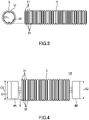
FIG. 3 illustrates an electric wire protection tube ofFIG. 1 in a front view (left side) and a plan view (right side); -
FIG. 4 is a diagram for illustrating a method of manufacturing the wire harness ofFIG. 1 ; -
FIG. 5 is a diagram for illustrating one example of a method of manufacturing the electric wire protection tube ofFIG. 1 ; -
FIG. 6 is a diagram for illustrating another example of a method of manufacturing the electric wire protection tube ofFIG. 1 ; -
FIG. 7 is a diagram for illustrating still another example of a method of manufacturing the electric wire protection tube ofFIG. 1 ; -
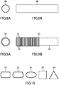
FIG. 8A and FIG. 8B illustrate a modified example of the electric wire protection tube ofFIG. 1 ,FIG. 8A being a front view andFIG. 8B being a plan view; -
FIG. 9A and FIG. 9B illustrate another modified example of the electric wire protection tube ofFIG. 1 ,FIG. 9A being a front view andFIG. 9B being a plan view; -
FIG. 10 shows front views of still another modified examples of the electric wire protection tube ofFIG. 1 ; -
FIG. 11 is a plan view of a wire harness according to a second embodiment of the present invention; -
FIG. 12 is a plan view of a wire harness according to a third embodiment of the present invention; -
FIG. 13 is a plan view of a wire harness according to a fourth embodiment of the present invention; and -
FIG. 14 is a cross-sectional view of a conventional wire harness. - A wire harness and a method of manufacturing the wire harness according to a first embodiment of the present invention will be described with reference to
FIG. 1 to FIG. 5 . - A
wire harness 1A shown inFIG. 1 is a wire harness configured to be wired in a vehicle. Thewire harness 1A includes a group ofelectric wires 2, an electricwire protection tube 3 covering said group ofelectric wires 2, andconnectors electric wires 2. - Each
electric wire 2 is a covered electric wire that includes a core wire covered with an insulation cover. - The electric
wire protection tube 3 is constituted of shape-memory polymer. The shape-memory polymer has a property of becoming soft at a temperature equal to or higher than a glass-transition point (Tg) and becoming rigid so a shape thereof is fixed when its temperature decreases below the glass-transition point. The shape-memory polymer further has a property that it memorizes a shape initially given (hereinafter, this memorized shape is referred to as "shape-memory shape"), and that, after it is deformed due to applied force, when it is heated again to a temperature equal to or higher than the glass-transition point, it is restored by itself to the shape-memory shape. - As shown in
FIG. 3 , the electricwire protection tube 3 of the shape-memory shape is formed into a corrugated-tube shape including continuously and alternately arrangedcrests 31 andtroughs 32, and the electricwire protection tube 3 is flexible. The electricwire protection tube 3 does not have a cut (slit) and a seam (i.e., a line of junction where cut portions are joined). - In the present invention, the material and the glass-transition point of the shape-memory polymer constituting the electric
wire protection tube 3 can be configured arbitrarily. For example, for thewire harness 1A of this embodiment, since it is intended to be wired in a vehicle, the glass-transition point may appropriately be higher than an ambient temperature in an environment where it is wired in a vehicle body. -
Connectors electric wires 2, and a connector housing made of synthetic resin accommodating the terminal fittings. Theconnectors wire protection tube 3 and are exposed. - As shown in
FIG. 1 and FIG. 2 , outer dimensions S1, S2 (S1=S2) of theconnectors electric wires 2 is greater than an inner dimension D1 (i.e., a diameter of the trough 32) of the electricwire protection tube 3 of the shape-memory shape. Thus, the group ofelectric wires 2 which is being connected to theconnectors wire protection tube 3 of the shape-memory shape, even by e.g., changing an angle of theconnectors connector - Next, a method of manufacturing the above-described
wire harness 1A will be described. A method of manufacturing thewire harness 1A of this embodiment is a method of mounting the electricwire protection tube 3 on the group ofelectric wires 2 which has been connected to theconnectors wire protection tube 3 afterword. - The electric
wire protection tube 3 is manufactured by a manufacturing installation shown inFIG. 5 . Anextruder 51 ofFIG. 5 is configured to heat and plasticize charged pellet-like shape-memory polymer and to extrude it in a tube shape. A shapingmachine 52 is configured to form protrusions and recesses, i.e., thecrests 31 and thetroughs 32, on a tube-shaped body extruded from theextruder 51. The tube-shaped body that has passed through the shapingmachine 52 is cooled and solidified until it is taken into a take-inmachine 53, thereby the tube-shaped body is shaped as the electricwire protection tube 3 of the shape-memory shape (a step of shaping). - A
heater 54 disposed downstream of the take-inmachine 53 is configured to heat the electricwire protection tube 3 to a temperature equal to or higher than the glass-transition point. The manufacturing installation ofFIG. 5 is further provided with an air feeder not shown for blowing compressed air in the electricwire protection tube 3 while it is being passed through theheater 54, as indicated by arrows. During this time, a tip of the electric wire protection tube 3 (i.e., an end thereof located on a side of a winder 55) is sealed. Thus, the electricwire protection tube 3 becomes inflated due to the compressed air blown therein, and the inner dimension thereof is expanded to the inner dimension D2 which is larger than the outer dimensions S1, S2 of theconnectors - The electric
wire protection tube 3 which has been expanded as described above is cooled to a temperature below the glass-transition point and solidified until it is wound on the winder 55 (a step of cooling), and then the electricwire protection tube 3 is wound on thewinder 55 while keeping its expanded shape. - Subsequently, the electric
wire protection tube 3 of the expanded shape that is drawn out from thewinder 55 is cut to a predetermined length, and, as shown inFIG. 4 , the group ofelectric wires 2 that is being connected to theconnectors wire protection tube 3 is larger than the outer dimensions S1, S2 of bothconnectors wire protection tube 3 can be mounted on the group ofelectric wires 2 by passing theconnector 4A and the group ofelectric wires 2 inside the electricwire protection tube 3, or alternatively, the electricwire protection tube 3 can be mounted on the group ofelectric wires 2 by passing theconnector 4B and the group ofelectric wires 2 inside the electricwire protection tube 3. - The electric
wire protection tube 3 that has been mounted on the group ofelectric wires 2 as described above is heated again by a heater not shown to a temperature equal to or higher than the glass-transition point, and the inner dimension of the electricwire protection tube 3 is restored to the inner dimension D1 of the shape-memory shape obtained before the expanding (a step of reheating). Thewire harness 1A is manufactured via these steps. - According to the method of manufacturing the
wire harness 1A of this embodiment, since the electricwire protection tube 3 that is expanded to the inner dimension larger than the outer dimensions of theconnectors electric wires 2, there is no need to form a slit on the electricwire protection tube 3, thus the electricwire protection tube 3 can be easily mounted on the group ofelectric wires 2. Further, since no slit is formed on the electricwire protection tube 3, it is possible to eliminate the tape winding operation as conventionally performed for preventing the electric wire from protruding out of the tube via the slit. In thewire harness 1A of this embodiment, however, a tape winding operation may be performed as needed to prevent the positional displacement between the electricwire protection tube 3 and the group ofelectric wires 2. - Further, the
wire harness 1A of the finished product is restored to the shape-memory shape in which the inner dimension of the electricwire protection tube 3 is smaller than the outer dimensions of theconnectors wire harness 1A can be wired through narrow wiring paths. Further, since the electricwire protection tube 3 is devoid of a slit or an edge (such as theend portion 531 inFIG. 14 ), damage to the cover of the electric wire can be prevented. - In the above-described
wire harness 1A, the outer dimension S1 of theconnector 4A and the outer dimension S2 of theconnector 4B are equal to each other; however, for example in the case where the outer dimension of theconnector 4A is smaller than the outer dimension of theconnector 4B, the electricwire protection tube 3 may be expanded so that the inner dimension thereof becomes larger than the outer dimension of theconnector 4A, and theconnector 4A and the group ofelectric wires 2 may be passed inside the electricwire protection tube 3 to mount the electricwire protection tube 3 on the group ofelectric wires 2. - In the above-described manufacturing installation of
FIG. 5 , the steps of shaping and expanding the electricwire protection tube 3 are performed in the same line; however, the steps of shaping and expanding the electricwire protection tube 3 may be performed in separate lines as shown inFIG. 6 . - On a
drum 61 shown inFIG. 6 , the electricwire protection tube 3 of the shape-memory shape is wound. This electricwire protection tube 3 is taken into a take-inmachine 62 and supplied to aheater 63. In the step performed at theheater 63, which is the same as the step at theheater 54 ofFIG. 5 , while the electricwire protection tube 3 is heated to a temperature equal to or higher than the glass-transition point, the compressed air is blown into the electricwire protection tube 3 to expand the electricwire protection tube 3. This expanded electricwire protection tube 3 is cooled to a temperature below the glass-transition point and solidified until it is wound on awinder 64, and then the electricwire protection tube 3 is wound on thewinder 64 while keeping its expanded shape. - In the above-described manufacturing installations of
FIG. 5 andFIG. 6 , the electricwire protection tube 3 is expanded by blowing the compressed air into the electricwire protection tube 3; however, the step of expanding the electricwire protection tube 3 may be performed using a manufacturing installation shown inFIG. 7 . - In the manufacturing installation of
FIG. 7 , the electricwire protection tube 3 of the shape-memory shape which has been cut to a predetermined length is heated by aheater 71 to a temperature equal to or higher than the glass-transition point. Then, anexpander 72 is inserted into the heated electricwire protection tube 3, and theexpander 72 is moved in an expanding direction to expand the electricwire protection tube 3. - In an alternate embodiment other than the one using the
expander 72 ofFIG. 7 , the heated electricwire protection tube 3 may be expanded by pulling it from the outside. - Further, in the present invention, electric
wire protection tubes FIG. 8A to FIG. 10 other than the above-described electricwire protection tube 3 may be used. These electricwire protection tubes - The electric
wire protection tube 3B shown inFIG. 8A and FIG. 8B is formed in the tube shape having an inner diameter and an outer diameter that are constant over the entire length. The electricwire protection tube 3C shown inFIG. 9A and FIG. 9B includes a corrugated tube-shaped portion where crests 31 andtroughs 32 are arranged continuously and alternately and astraight portion 33 where an inner diameter and an outer diameter thereof are constant. - For the electric
wire protection tubes wire protection tube 3D ofFIG. 10 , a cross section perpendicular to the axial direction is a shape of a rectangle. For the electricwire protection tube 3E ofFIG. 10 , a cross section perpendicular to the axial direction is a shape of an oval. For the electricwire protection tube 3F ofFIG. 10 , a cross section perpendicular to the axial direction is a shape of an ellipse. For the electricwire protection tube 3G ofFIG. 10 , a cross section perpendicular to the axial direction is a shape of a square. For the electricwire protection tube 3H ofFIG. 10 , a cross section perpendicular to the axial direction is a shape of an equilateral triangle. - A wire harness and a method of manufacturing the wire harness according to a second embodiment of the present invention will be described with reference to
FIG. 11 . InFIG. 11 , the same elements as the first embodiment described above are provided with the same reference signs and explanations thereof are omitted. - A
wire harness 1B shown inFIG. 11 is a wire harness configured to be wired in a vehicle. Thewire harness 1B includes a singleelectric wire 2, an electricwire protection tube 3 covering theelectric wire 2, around terminal 8 connected to one end of theelectric wire 2, and a large-dimension portion not shown provided at the other end of theelectric wire 2. Theround terminal 8 and the large-dimension portion are not covered by the electricwire protection tube 3 and are exposed. - An outer dimension S3 of the
round terminal 8 in a direction perpendicular to theelectric wire 2 is larger than an inner dimension D1 (i.e., a diameter of the trough 32) of the electricwire protection tube 3 of the shape-memory shape. Thisround terminal 8 corresponds to "large-dimension portion" in claims. An outer dimension of the above-described large-dimension portion in the direction perpendicular to theelectric wire 2 is also larger than the inner dimension D1 of the electricwire protection tube 3 of the shape-memory shape. Thus, theelectric wire 2 that is being connected to theround terminal 8, i.e., the large-dimension portion, cannot be passed inside the electricwire protection tube 3 of the shape-memory shape even by e.g., changing an angle of theround terminal 8, i.e., the large-dimension portion. - Similarly to the first embodiment, a method of manufacturing the
wire harness 1B is a method of mounting the electricwire protection tube 3 on theelectric wire 2 that has been connected to theround terminal 8, i.e., the large-dimension portion, in other words, it is a method of mounting the electricwire protection tube 3 afterword. - In this embodiment also, similarly to the first embodiment, the electric
wire protection tube 3 is expanded such that the inner dimension thereof becomes larger than the outer dimension of theround terminal 8, i.e., the large-dimension portion, to mount the electricwire protection tube 3 on theelectric wire 2. After the electricwire protection tube 3 is mounted on theelectric wire 2, the electricwire protection tube 3 is heated again to a temperature equal to or higher than the glass-transition point so it is restored to the shape-memory shape. - A wire harness and a method of manufacturing the wire harness according to a third embodiment of the present invention will be described with reference to
FIG. 12 . InFIG. 12 , the same elements as the first embodiment described above are provided with the same reference signs and explanations thereof are omitted. - A
wire harness 1C shown inFIG. 12 is a wire harness configured to be wired to a vehicle. Thewire harness 1C includes a group ofelectric wires 2, an electricwire protection tube 3 covering the group ofelectric wires 2, anelectric connection box 9 connected to one end of the group ofelectric wires 2, and a large-dimension portion not shown provided on the other end of the group ofelectric wires 2. Theelectric connection box 9 and the large-dimension portion are not covered by the electricwire protection tube 3 and are exposed. - The
electric connection box 9 includes a case made of synthetic resin and components such as a relay and a fuse mounted on the case. - An outer dimension S4 of the
electric connection box 9 in a direction perpendicular to theelectric wire 2 is larger than an inner dimension D1 (i.e., a diameter of the trough 32) of the electricwire protection tube 3 of the shape-memory shape. Thiselectric connection box 9 corresponds to "large-dimension portion" in claims. An outer dimension of the above-described large-dimension portion in the direction perpendicular to theelectric wire 2 is also larger than the inner dimension D1 of the electricwire protection tube 3 of the shape-memory shape. Thus, the group ofelectric wires 2 that is being connected to theelectric connection box 9, i.e., the large-dimension portion, cannot be passed inside the electricwire protection tube 3 of the shape-memory shape even by e.g., changing an angle of theelectric connection box 9, i.e., the large-dimension portion. - Similarly to the first embodiment, a method of manufacturing the above-described
wire harness 1C is a method of mounting the electricwire protection tube 3 on the group ofelectric wires 2 that has been connected to theelectric connection box 9, i.e., the large-dimension portion, in other words, it is a method of mounting the electricwire protection tube 3 afterward. - In this embodiment also, similarly to the first embodiment, the electric
wire protection tube 3 is expanded such that the inner dimension thereof becomes larger than the outer dimension of theelectric connection box 9, i.e., the large-dimension portion, to mount the electricwire protection tube 3 on the group ofelectric wires 2. After the electricwire protection tube 3 is mounted on the group ofelectric wires 2, the electricwire protection tube 3 is heated again to a temperature equal to or higher than the glass-transition point so it is restored to the shape-memory shape. - A wire harness and a method of manufacturing a wire harness according to a fourth embodiment of the present invention will be described with reference to
FIG. 13 . InFIG. 13 , the same components as the first embodiment described above are provided with the same reference signs and explanations thereof are omitted. - A wire harness ID shown in
FIG. 13 is a wire harness configured to be wired in the vehicle. The wire harness ID includes a group ofelectric wires 2 and an electricwire protection tube 3 covering said group ofelectric wires 2. The group ofelectric wires 2 is provided withbranch portions wire protection tube 3 is mounted on a part between thebranch portion 10 and thebranch portion 11. - Dimensions S5, S6 of the
branch portions wire protection tube 3 are larger than an inner dimension D1 (i.e., a diameter of the trough 32) of the electricwire protection tube 3 of the shape-memory shape. Such group ofelectric wires 2 cannot be passed inside the electricwire protection tube 3 of the shape-memory shape even by bending or twisting it because thebranch portion 10 side or thebranch portion 11 side is caught by the electricwire protection tube 3. Thebranch portion - A method of manufacturing the wire harness ID is a method of mounting the electric
wire protection tube 3 on the group ofelectric wires 2 that has been provided with thebranch portions wire protection tube 3 afterward. - In this example also, the electric
wire protection tube 3 is expanded and mounted on the group ofelectric wires 2. The electricwire protection tube 3 is expanded to a size that allows a part of the group ofelectric wires 2 ahead of the branch portion 10 (i.e., a part on an opposite side of the branch portion 11) or a part of the group ofelectric wires 2 ahead of the branch portion 11 (i.e., a part on an opposite side of the branch portion 10) to be passed inside the electricwire protection tube 3. Subsequently, the electricwire protection tube 3 is heated again to a temperature equal to or higher than the glass-transition point and so it is restored to the shape-memory shape. - The embodiments described above are only representative embodiments of the present invention, and the present invention is not limited thereto. That is, those skilled in the art can carry out various modifications according to conventionally known knowledge without departing from the gist of the present invention. Such modifications, as long as they have the configuration of the present invention, are still within the present invention.
-
- 1A, 1B, 1C, ID
- wire harness
- 2
- electric wire
- 3, 3B, 3C, 3D, 3E, 3F, 3G, 3H
- electric wire protection tube
- 4A, 4B
- connector (large-dimension portion)
- 8
- round terminal (large-dimension portion)
- 9
- electric connection box (large-dimension portion)
- 10, 11
- branch portion (large-dimension portion)
Claims (4)
- A method of manufacturing a wire harness (1A, 1B, 1C, ID) that includes an electric wire (2) and an electric wire protection tube (3, 3B, 3C, 3D, 3E, 3F, 3G, 3H) covering the electric wire (2), one end side of the electric wire (2) being provided with a large-dimension portion (4A, 4B, 8, 9, 10, 11) having a dimension larger than an inner dimension of the electric wire protection tube (3, 3B, 3C, 3D, 3E, 3F, 3G, 3H),
the method comprising mounting the electric wire protection tube (3, 3B, 3C, 3D, 3E, 3F, 3G, 3H) on the electric wire (2) via steps, performed in a sequence set forth, of:shaping the electric wire protection tube (3, 3B, 3C, 3D, 3E, 3F, 3G, 3H) made of shape-memory polymer into a tube shape;expanding the electric wire protection tube (3, 3B, 3C, 3D, 3E, 3F, 3G, 3H) which is heated to a temperature equal to or higher than a glass-transition point such that the inner dimension of the electric wire protection tube (3, 3B, 3C, 3D, 3E, 3F, 3G, 3H) becomes larger than the dimension of the large-dimension portion (4A, 4B, 8, 9, 10, 11);while the electric wire protection tube (3, 3B, 3C, 3D, 3E, 3F, 3G, 3H) is in an expanded state, cooling the electric wire protection tube (3, 3B, 3C, 3D, 3E, 3F, 3G, 3H) to a temperature below the glass-transition point and solidifying the electric wire protection tube (3, 3B, 3C, 3D, 3E, 3F, 3G, 3H);mounting the electric wire protection tube (3, 3B, 3C, 3D, 3E, 3F, 3G, 3H) on the electric wire by passing the large-dimension portion (4A, 4B, 8, 9, 10, 11) and the electric wire (2) inside the electric wire protection tube (3, 3B, 3C, 3D, 3E, 3F, 3G, 3H); andreheating the electric wire protection tube (3, 3B, 3C, 3D, 3E, 3F, 3G, 3H) to a temperature equal to or higher than the glass-transition point such that the electric wire protection tube (3, 3B, 3C, 3D, 3E, 3F, 3G, 3H) is restored to the inner dimension obtained after the step of shaping. - The method according to claim 1, wherein
in the step of expanding, the electric wire protection tube (3, 3B, 3C, 3D, 3E, 3F, 3G, 3H) is expanded by blowing compressed air in the electric wire protection tube (3, 3B, 3C, 3D, 3E, 3F, 3G, 3H). - The method according to claim 1, wherein
in the step of expanding, an expander (72) is inserted into the electric wire protection tube (3, 3B, 3C, 3D, 3E, 3F, 3G, 3H), and the expander is moved to expand the electric wire protection tube (3, 3B, 3C, 3D, 3E, 3F, 3G, 3H). - A wire harness (1A, 1B, 1C, ID) comprising:an electric wire (2);an electric wire protection tube (3, 3B, 3C, 3D, 3E, 3F, 3G, 3H) covering the electric wire (2); andlarge-dimension portions (4A, 4B, 8, 9, 10, 11) provided at both end sides of the electric wire (2), respectively, and each having a dimension larger than an inner dimension of the electric wire protection tube (3, 3B, 3C, 3D, 3E, 3F, 3G, 3H),wherein the electric wire protection tube (3, 3B, 3C, 3D, 3E, 3F, 3G, 3H) is constituted of shape-memory polymer and is devoid of a cut and a seam.
Applications Claiming Priority (1)
| Application Number | Priority Date | Filing Date | Title |
|---|---|---|---|
| JP2021021619A JP2022124071A (en) | 2021-02-15 | 2021-02-15 | Wire harness, method for manufacturing wire harness |
Publications (2)
| Publication Number | Publication Date |
|---|---|
| EP4044383A1 true EP4044383A1 (en) | 2022-08-17 |
| EP4044383B1 EP4044383B1 (en) | 2023-02-15 |
Family
ID=80446919
Family Applications (1)
| Application Number | Title | Priority Date | Filing Date |
|---|---|---|---|
| EP22154520.5A Active EP4044383B1 (en) | 2021-02-15 | 2022-02-01 | Wire harness and method of manufacturing wire harness |
Country Status (4)
| Country | Link |
|---|---|
| US (1) | US11915841B2 (en) |
| EP (1) | EP4044383B1 (en) |
| JP (1) | JP2022124071A (en) |
| CN (1) | CN114944256A (en) |
Families Citing this family (1)
| Publication number | Priority date | Publication date | Assignee | Title |
|---|---|---|---|---|
| JP2025001901A (en) * | 2023-06-21 | 2025-01-09 | 住友電装株式会社 | Exterior member and wire harness |
Citations (6)
| Publication number | Priority date | Publication date | Assignee | Title |
|---|---|---|---|---|
| JP2000165061A (en) * | 1998-11-30 | 2000-06-16 | Sumitomo Wiring Syst Ltd | Method and structure for turning off water between cables of grommet |
| WO2012043037A1 (en) * | 2010-10-01 | 2012-04-05 | 矢崎総業株式会社 | Wire harness and method for producing wire harness |
| JP2015019527A (en) * | 2013-07-12 | 2015-01-29 | 住友電装株式会社 | Protective material for wiring harness, and protective structure for wiring harness |
| JP2016046914A (en) * | 2014-08-22 | 2016-04-04 | 株式会社オートネットワーク技術研究所 | Heat-shrinkable corrugated tube, method for producing heat-shrinkable corrugated tube, and method for producing a wiring module with a protective member |
| JP2016110880A (en) | 2014-12-08 | 2016-06-20 | 住友電装株式会社 | Wire harness and producing method of wire harness |
| US20160365170A1 (en) * | 2015-06-10 | 2016-12-15 | Sumitomo Wiring Systems, Ltd. | Protector and wire harness |
Family Cites Families (6)
| Publication number | Priority date | Publication date | Assignee | Title |
|---|---|---|---|---|
| US4929478A (en) * | 1988-06-17 | 1990-05-29 | The Bentley-Harris Manufacturing Company | Protective fabric sleeves |
| US5627343A (en) * | 1994-08-03 | 1997-05-06 | Xl Technologies, Inc. | Re-enterable conduit sealing assembly |
| CN101189773B (en) * | 2005-06-02 | 2010-09-08 | 住友电装株式会社 | Waterproof method and structure of wire end joint part |
| JP5569385B2 (en) * | 2010-12-22 | 2014-08-13 | 住友電装株式会社 | Slit shrink tube, wire harness, and manufacturing method of slit shrink tube |
| JP2014073637A (en) * | 2012-10-04 | 2014-04-24 | Sumitomo Electric Fine Polymer Inc | Heat-shrinkable tubing |
| WO2015119688A2 (en) * | 2013-11-18 | 2015-08-13 | University Of Florida Research Foundation, Inc. | Shape-memory-self-healing polymers (smshps) |
-
2021
- 2021-02-15 JP JP2021021619A patent/JP2022124071A/en active Pending
-
2022
- 2022-01-19 US US17/579,201 patent/US11915841B2/en active Active
- 2022-01-25 CN CN202210086606.6A patent/CN114944256A/en not_active Withdrawn
- 2022-02-01 EP EP22154520.5A patent/EP4044383B1/en active Active
Patent Citations (6)
| Publication number | Priority date | Publication date | Assignee | Title |
|---|---|---|---|---|
| JP2000165061A (en) * | 1998-11-30 | 2000-06-16 | Sumitomo Wiring Syst Ltd | Method and structure for turning off water between cables of grommet |
| WO2012043037A1 (en) * | 2010-10-01 | 2012-04-05 | 矢崎総業株式会社 | Wire harness and method for producing wire harness |
| JP2015019527A (en) * | 2013-07-12 | 2015-01-29 | 住友電装株式会社 | Protective material for wiring harness, and protective structure for wiring harness |
| JP2016046914A (en) * | 2014-08-22 | 2016-04-04 | 株式会社オートネットワーク技術研究所 | Heat-shrinkable corrugated tube, method for producing heat-shrinkable corrugated tube, and method for producing a wiring module with a protective member |
| JP2016110880A (en) | 2014-12-08 | 2016-06-20 | 住友電装株式会社 | Wire harness and producing method of wire harness |
| US20160365170A1 (en) * | 2015-06-10 | 2016-12-15 | Sumitomo Wiring Systems, Ltd. | Protector and wire harness |
Also Published As
| Publication number | Publication date |
|---|---|
| CN114944256A (en) | 2022-08-26 |
| JP2022124071A (en) | 2022-08-25 |
| US11915841B2 (en) | 2024-02-27 |
| EP4044383B1 (en) | 2023-02-15 |
| US20220262547A1 (en) | 2022-08-18 |
Similar Documents
| Publication | Publication Date | Title |
|---|---|---|
| CN101484741B (en) | Ringed tubular sheath and device for making such a sheath | |
| EP4044383A1 (en) | Wire harness and method of manufacturing wire harness | |
| US9653197B2 (en) | Wire harness, wire harness manufacturing method and wire harness manufacturing apparatus | |
| US10630020B2 (en) | Cable connection structure and manufacturing method of the cable connection structure | |
| US20160064906A1 (en) | Wire harness electrical line exterior structure | |
| JP2015019527A (en) | Protective material for wiring harness, and protective structure for wiring harness | |
| JP4250527B2 (en) | Multi-component insulation coating product | |
| WO2016111119A1 (en) | Wiring module and wiring module production method | |
| JP6052097B2 (en) | Manufacturing method of wire harness with protector | |
| JP6168014B2 (en) | Wiring module and method of manufacturing wiring module | |
| WO2016027690A1 (en) | Heat-shrinkable corrugated tube, production method for heat-shrinkable corrugated tube, and production method for wiring module with protection member | |
| US20170162293A1 (en) | Wire harness | |
| JPH10134640A (en) | Cable and manufacturing method thereof | |
| US10236096B2 (en) | Wire harness and manufacturing method of wire harness | |
| CN113276381A (en) | Method for manufacturing spiral pipe | |
| EP3785999B1 (en) | Electric wire protection member and method for manufacturing electric wire protection member | |
| JP7219130B2 (en) | Wire harness outer tube manufacturing apparatus and wire harness outer tube manufacturing method | |
| JP2006014398A (en) | Corrugate tube for wire harness | |
| JP6241885B2 (en) | Covered wire, covered wire intermediate material, wire harness, and method of manufacturing covered wire | |
| JPH11111066A (en) | cable | |
| EP3437840A1 (en) | Resin component and method for manufacturing resin component | |
| JP2015223027A (en) | Corrugated tube for wiring harness and wiring harness | |
| JP2022024308A (en) | Shrinkable tube and manufacturing method for shrinkable tube | |
| JP2000071343A (en) | Tube heat treatment method | |
| WO2017169190A1 (en) | Resin component and method for manufacturing resin component |
Legal Events
| Date | Code | Title | Description |
|---|---|---|---|
| PUAI | Public reference made under article 153(3) epc to a published international application that has entered the european phase |
Free format text: ORIGINAL CODE: 0009012 |
|
| STAA | Information on the status of an ep patent application or granted ep patent |
Free format text: STATUS: REQUEST FOR EXAMINATION WAS MADE |
|
| 17P | Request for examination filed |
Effective date: 20220201 |
|
| AK | Designated contracting states |
Kind code of ref document: A1 Designated state(s): AL AT BE BG CH CY CZ DE DK EE ES FI FR GB GR HR HU IE IS IT LI LT LU LV MC MK MT NL NO PL PT RO RS SE SI SK SM TR |
|
| RBV | Designated contracting states (corrected) |
Designated state(s): AL AT BE BG CH CY CZ DE DK EE ES FI FR GB GR HR HU IE IS IT LI LT LU LV MC MK MT NL NO PL PT RO RS SE SI SK SM TR |
|
| GRAP | Despatch of communication of intention to grant a patent |
Free format text: ORIGINAL CODE: EPIDOSNIGR1 |
|
| STAA | Information on the status of an ep patent application or granted ep patent |
Free format text: STATUS: GRANT OF PATENT IS INTENDED |
|
| INTG | Intention to grant announced |
Effective date: 20221201 |
|
| GRAS | Grant fee paid |
Free format text: ORIGINAL CODE: EPIDOSNIGR3 |
|
| GRAA | (expected) grant |
Free format text: ORIGINAL CODE: 0009210 |
|
| STAA | Information on the status of an ep patent application or granted ep patent |
Free format text: STATUS: THE PATENT HAS BEEN GRANTED |
|
| AK | Designated contracting states |
Kind code of ref document: B1 Designated state(s): AL AT BE BG CH CY CZ DE DK EE ES FI FR GB GR HR HU IE IS IT LI LT LU LV MC MK MT NL NO PL PT RO RS SE SI SK SM TR |
|
| REG | Reference to a national code |
Ref country code: CH Ref legal event code: EP Ref country code: GB Ref legal event code: FG4D |
|
| REG | Reference to a national code |
Ref country code: DE Ref legal event code: R096 Ref document number: 602022000007 Country of ref document: DE |
|
| REG | Reference to a national code |
Ref country code: AT Ref legal event code: REF Ref document number: 1548751 Country of ref document: AT Kind code of ref document: T Effective date: 20230315 Ref country code: IE Ref legal event code: FG4D |
|
| RAP4 | Party data changed (patent owner data changed or rights of a patent transferred) |
Owner name: YAZAKI CORPORATION |
|
| REG | Reference to a national code |
Ref country code: LT Ref legal event code: MG9D |
|
| REG | Reference to a national code |
Ref country code: NL Ref legal event code: MP Effective date: 20230215 |
|
| REG | Reference to a national code |
Ref country code: AT Ref legal event code: MK05 Ref document number: 1548751 Country of ref document: AT Kind code of ref document: T Effective date: 20230215 |
|
| PG25 | Lapsed in a contracting state [announced via postgrant information from national office to epo] |
Ref country code: RS Free format text: LAPSE BECAUSE OF FAILURE TO SUBMIT A TRANSLATION OF THE DESCRIPTION OR TO PAY THE FEE WITHIN THE PRESCRIBED TIME-LIMIT Effective date: 20230215 Ref country code: PT Free format text: LAPSE BECAUSE OF FAILURE TO SUBMIT A TRANSLATION OF THE DESCRIPTION OR TO PAY THE FEE WITHIN THE PRESCRIBED TIME-LIMIT Effective date: 20230615 Ref country code: NO Free format text: LAPSE BECAUSE OF FAILURE TO SUBMIT A TRANSLATION OF THE DESCRIPTION OR TO PAY THE FEE WITHIN THE PRESCRIBED TIME-LIMIT Effective date: 20230515 Ref country code: NL Free format text: LAPSE BECAUSE OF FAILURE TO SUBMIT A TRANSLATION OF THE DESCRIPTION OR TO PAY THE FEE WITHIN THE PRESCRIBED TIME-LIMIT Effective date: 20230215 Ref country code: LV Free format text: LAPSE BECAUSE OF FAILURE TO SUBMIT A TRANSLATION OF THE DESCRIPTION OR TO PAY THE FEE WITHIN THE PRESCRIBED TIME-LIMIT Effective date: 20230215 Ref country code: LT Free format text: LAPSE BECAUSE OF FAILURE TO SUBMIT A TRANSLATION OF THE DESCRIPTION OR TO PAY THE FEE WITHIN THE PRESCRIBED TIME-LIMIT Effective date: 20230215 Ref country code: HR Free format text: LAPSE BECAUSE OF FAILURE TO SUBMIT A TRANSLATION OF THE DESCRIPTION OR TO PAY THE FEE WITHIN THE PRESCRIBED TIME-LIMIT Effective date: 20230215 Ref country code: ES Free format text: LAPSE BECAUSE OF FAILURE TO SUBMIT A TRANSLATION OF THE DESCRIPTION OR TO PAY THE FEE WITHIN THE PRESCRIBED TIME-LIMIT Effective date: 20230215 Ref country code: AT Free format text: LAPSE BECAUSE OF FAILURE TO SUBMIT A TRANSLATION OF THE DESCRIPTION OR TO PAY THE FEE WITHIN THE PRESCRIBED TIME-LIMIT Effective date: 20230215 |
|
| PG25 | Lapsed in a contracting state [announced via postgrant information from national office to epo] |
Ref country code: SE Free format text: LAPSE BECAUSE OF FAILURE TO SUBMIT A TRANSLATION OF THE DESCRIPTION OR TO PAY THE FEE WITHIN THE PRESCRIBED TIME-LIMIT Effective date: 20230215 Ref country code: PL Free format text: LAPSE BECAUSE OF FAILURE TO SUBMIT A TRANSLATION OF THE DESCRIPTION OR TO PAY THE FEE WITHIN THE PRESCRIBED TIME-LIMIT Effective date: 20230215 Ref country code: IS Free format text: LAPSE BECAUSE OF FAILURE TO SUBMIT A TRANSLATION OF THE DESCRIPTION OR TO PAY THE FEE WITHIN THE PRESCRIBED TIME-LIMIT Effective date: 20230615 Ref country code: GR Free format text: LAPSE BECAUSE OF FAILURE TO SUBMIT A TRANSLATION OF THE DESCRIPTION OR TO PAY THE FEE WITHIN THE PRESCRIBED TIME-LIMIT Effective date: 20230516 Ref country code: FI Free format text: LAPSE BECAUSE OF FAILURE TO SUBMIT A TRANSLATION OF THE DESCRIPTION OR TO PAY THE FEE WITHIN THE PRESCRIBED TIME-LIMIT Effective date: 20230215 |
|
| PG25 | Lapsed in a contracting state [announced via postgrant information from national office to epo] |
Ref country code: SM Free format text: LAPSE BECAUSE OF FAILURE TO SUBMIT A TRANSLATION OF THE DESCRIPTION OR TO PAY THE FEE WITHIN THE PRESCRIBED TIME-LIMIT Effective date: 20230215 Ref country code: RO Free format text: LAPSE BECAUSE OF FAILURE TO SUBMIT A TRANSLATION OF THE DESCRIPTION OR TO PAY THE FEE WITHIN THE PRESCRIBED TIME-LIMIT Effective date: 20230215 Ref country code: EE Free format text: LAPSE BECAUSE OF FAILURE TO SUBMIT A TRANSLATION OF THE DESCRIPTION OR TO PAY THE FEE WITHIN THE PRESCRIBED TIME-LIMIT Effective date: 20230215 Ref country code: DK Free format text: LAPSE BECAUSE OF FAILURE TO SUBMIT A TRANSLATION OF THE DESCRIPTION OR TO PAY THE FEE WITHIN THE PRESCRIBED TIME-LIMIT Effective date: 20230215 Ref country code: CZ Free format text: LAPSE BECAUSE OF FAILURE TO SUBMIT A TRANSLATION OF THE DESCRIPTION OR TO PAY THE FEE WITHIN THE PRESCRIBED TIME-LIMIT Effective date: 20230215 |
|
| REG | Reference to a national code |
Ref country code: DE Ref legal event code: R097 Ref document number: 602022000007 Country of ref document: DE |
|
| PG25 | Lapsed in a contracting state [announced via postgrant information from national office to epo] |
Ref country code: SK Free format text: LAPSE BECAUSE OF FAILURE TO SUBMIT A TRANSLATION OF THE DESCRIPTION OR TO PAY THE FEE WITHIN THE PRESCRIBED TIME-LIMIT Effective date: 20230215 |
|
| PLBE | No opposition filed within time limit |
Free format text: ORIGINAL CODE: 0009261 |
|
| STAA | Information on the status of an ep patent application or granted ep patent |
Free format text: STATUS: NO OPPOSITION FILED WITHIN TIME LIMIT |
|
| 26N | No opposition filed |
Effective date: 20231116 |
|
| PG25 | Lapsed in a contracting state [announced via postgrant information from national office to epo] |
Ref country code: SI Free format text: LAPSE BECAUSE OF FAILURE TO SUBMIT A TRANSLATION OF THE DESCRIPTION OR TO PAY THE FEE WITHIN THE PRESCRIBED TIME-LIMIT Effective date: 20230215 |
|
| PG25 | Lapsed in a contracting state [announced via postgrant information from national office to epo] |
Ref country code: IT Free format text: LAPSE BECAUSE OF FAILURE TO SUBMIT A TRANSLATION OF THE DESCRIPTION OR TO PAY THE FEE WITHIN THE PRESCRIBED TIME-LIMIT Effective date: 20230215 |
|
| PG25 | Lapsed in a contracting state [announced via postgrant information from national office to epo] |
Ref country code: MC Free format text: LAPSE BECAUSE OF FAILURE TO SUBMIT A TRANSLATION OF THE DESCRIPTION OR TO PAY THE FEE WITHIN THE PRESCRIBED TIME-LIMIT Effective date: 20230215 |
|
| PG25 | Lapsed in a contracting state [announced via postgrant information from national office to epo] |
Ref country code: LU Free format text: LAPSE BECAUSE OF NON-PAYMENT OF DUE FEES Effective date: 20240201 |
|
| PG25 | Lapsed in a contracting state [announced via postgrant information from national office to epo] |
Ref country code: LU Free format text: LAPSE BECAUSE OF NON-PAYMENT OF DUE FEES Effective date: 20240201 |
|
| PG25 | Lapsed in a contracting state [announced via postgrant information from national office to epo] |
Ref country code: BG Free format text: LAPSE BECAUSE OF FAILURE TO SUBMIT A TRANSLATION OF THE DESCRIPTION OR TO PAY THE FEE WITHIN THE PRESCRIBED TIME-LIMIT Effective date: 20230215 |
|
| PG25 | Lapsed in a contracting state [announced via postgrant information from national office to epo] |
Ref country code: BG Free format text: LAPSE BECAUSE OF FAILURE TO SUBMIT A TRANSLATION OF THE DESCRIPTION OR TO PAY THE FEE WITHIN THE PRESCRIBED TIME-LIMIT Effective date: 20230215 |
|
| REG | Reference to a national code |
Ref country code: BE Ref legal event code: MM Effective date: 20240229 |
|
| PG25 | Lapsed in a contracting state [announced via postgrant information from national office to epo] |
Ref country code: BE Free format text: LAPSE BECAUSE OF NON-PAYMENT OF DUE FEES Effective date: 20240229 |
|
| PG25 | Lapsed in a contracting state [announced via postgrant information from national office to epo] |
Ref country code: FR Free format text: LAPSE BECAUSE OF NON-PAYMENT OF DUE FEES Effective date: 20240229 |
|
| PG25 | Lapsed in a contracting state [announced via postgrant information from national office to epo] |
Ref country code: IE Free format text: LAPSE BECAUSE OF NON-PAYMENT OF DUE FEES Effective date: 20240201 |
|
| PG25 | Lapsed in a contracting state [announced via postgrant information from national office to epo] |
Ref country code: IE Free format text: LAPSE BECAUSE OF NON-PAYMENT OF DUE FEES Effective date: 20240201 Ref country code: FR Free format text: LAPSE BECAUSE OF NON-PAYMENT OF DUE FEES Effective date: 20240229 Ref country code: BE Free format text: LAPSE BECAUSE OF NON-PAYMENT OF DUE FEES Effective date: 20240229 |
|
| PG25 | Lapsed in a contracting state [announced via postgrant information from national office to epo] |
Ref country code: CY Free format text: LAPSE BECAUSE OF FAILURE TO SUBMIT A TRANSLATION OF THE DESCRIPTION OR TO PAY THE FEE WITHIN THE PRESCRIBED TIME-LIMIT; INVALID AB INITIO Effective date: 20220201 |
|
| REG | Reference to a national code |
Ref country code: CH Ref legal event code: PL |
|
| PG25 | Lapsed in a contracting state [announced via postgrant information from national office to epo] |
Ref country code: CH Free format text: LAPSE BECAUSE OF NON-PAYMENT OF DUE FEES Effective date: 20250228 |
|
| PG25 | Lapsed in a contracting state [announced via postgrant information from national office to epo] |
Ref country code: TR Free format text: LAPSE BECAUSE OF FAILURE TO SUBMIT A TRANSLATION OF THE DESCRIPTION OR TO PAY THE FEE WITHIN THE PRESCRIBED TIME-LIMIT Effective date: 20230215 |
|
| PGFP | Annual fee paid to national office [announced via postgrant information from national office to epo] |
Ref country code: DE Payment date: 20251230 Year of fee payment: 5 |