EP4044347B1 - Batterie, elektrische vorrichtung und herstellungsverfahren für eine batterie - Google Patents
Batterie, elektrische vorrichtung und herstellungsverfahren für eine batterie Download PDFInfo
- Publication number
- EP4044347B1 EP4044347B1 EP21820074.9A EP21820074A EP4044347B1 EP 4044347 B1 EP4044347 B1 EP 4044347B1 EP 21820074 A EP21820074 A EP 21820074A EP 4044347 B1 EP4044347 B1 EP 4044347B1
- Authority
- EP
- European Patent Office
- Prior art keywords
- battery
- mounting base
- battery cells
- battery cell
- connecting piece
- Prior art date
- Legal status (The legal status is an assumption and is not a legal conclusion. Google has not performed a legal analysis and makes no representation as to the accuracy of the status listed.)
- Active
Links
Images


Classifications
-
- H—ELECTRICITY
- H01—ELECTRIC ELEMENTS
- H01M—PROCESSES OR MEANS, e.g. BATTERIES, FOR THE DIRECT CONVERSION OF CHEMICAL ENERGY INTO ELECTRICAL ENERGY
- H01M50/00—Constructional details or processes of manufacture of the non-active parts of electrochemical cells other than fuel cells, e.g. hybrid cells
- H01M50/20—Mountings; Secondary casings or frames; Racks, modules or packs; Suspension devices; Shock absorbers; Transport or carrying devices; Holders
- H01M50/204—Racks, modules or packs for multiple batteries or multiple cells
-
- H—ELECTRICITY
- H01—ELECTRIC ELEMENTS
- H01M—PROCESSES OR MEANS, e.g. BATTERIES, FOR THE DIRECT CONVERSION OF CHEMICAL ENERGY INTO ELECTRICAL ENERGY
- H01M10/00—Secondary cells; Manufacture thereof
- H01M10/05—Accumulators with non-aqueous electrolyte
- H01M10/052—Li-accumulators
- H01M10/0525—Rocking-chair batteries, i.e. batteries with lithium insertion or intercalation in both electrodes; Lithium-ion batteries
-
- H—ELECTRICITY
- H01—ELECTRIC ELEMENTS
- H01M—PROCESSES OR MEANS, e.g. BATTERIES, FOR THE DIRECT CONVERSION OF CHEMICAL ENERGY INTO ELECTRICAL ENERGY
- H01M10/00—Secondary cells; Manufacture thereof
- H01M10/60—Heating or cooling; Temperature control
- H01M10/61—Types of temperature control
- H01M10/615—Heating or keeping warm
-
- H—ELECTRICITY
- H01—ELECTRIC ELEMENTS
- H01M—PROCESSES OR MEANS, e.g. BATTERIES, FOR THE DIRECT CONVERSION OF CHEMICAL ENERGY INTO ELECTRICAL ENERGY
- H01M10/00—Secondary cells; Manufacture thereof
- H01M10/60—Heating or cooling; Temperature control
- H01M10/62—Heating or cooling; Temperature control specially adapted for specific applications
- H01M10/625—Vehicles
-
- H—ELECTRICITY
- H01—ELECTRIC ELEMENTS
- H01M—PROCESSES OR MEANS, e.g. BATTERIES, FOR THE DIRECT CONVERSION OF CHEMICAL ENERGY INTO ELECTRICAL ENERGY
- H01M10/00—Secondary cells; Manufacture thereof
- H01M10/60—Heating or cooling; Temperature control
- H01M10/65—Means for temperature control structurally associated with the cells
- H01M10/655—Solid structures for heat exchange or heat conduction
-
- H—ELECTRICITY
- H01—ELECTRIC ELEMENTS
- H01M—PROCESSES OR MEANS, e.g. BATTERIES, FOR THE DIRECT CONVERSION OF CHEMICAL ENERGY INTO ELECTRICAL ENERGY
- H01M50/00—Constructional details or processes of manufacture of the non-active parts of electrochemical cells other than fuel cells, e.g. hybrid cells
- H01M50/20—Mountings; Secondary casings or frames; Racks, modules or packs; Suspension devices; Shock absorbers; Transport or carrying devices; Holders
- H01M50/204—Racks, modules or packs for multiple batteries or multiple cells
- H01M50/207—Racks, modules or packs for multiple batteries or multiple cells characterised by their shape
- H01M50/213—Racks, modules or packs for multiple batteries or multiple cells characterised by their shape adapted for cells having curved cross-section, e.g. round or elliptic
-
- H—ELECTRICITY
- H01—ELECTRIC ELEMENTS
- H01M—PROCESSES OR MEANS, e.g. BATTERIES, FOR THE DIRECT CONVERSION OF CHEMICAL ENERGY INTO ELECTRICAL ENERGY
- H01M50/00—Constructional details or processes of manufacture of the non-active parts of electrochemical cells other than fuel cells, e.g. hybrid cells
- H01M50/20—Mountings; Secondary casings or frames; Racks, modules or packs; Suspension devices; Shock absorbers; Transport or carrying devices; Holders
- H01M50/249—Mountings; Secondary casings or frames; Racks, modules or packs; Suspension devices; Shock absorbers; Transport or carrying devices; Holders specially adapted for aircraft or vehicles, e.g. cars or trains
-
- H—ELECTRICITY
- H01—ELECTRIC ELEMENTS
- H01M—PROCESSES OR MEANS, e.g. BATTERIES, FOR THE DIRECT CONVERSION OF CHEMICAL ENERGY INTO ELECTRICAL ENERGY
- H01M50/00—Constructional details or processes of manufacture of the non-active parts of electrochemical cells other than fuel cells, e.g. hybrid cells
- H01M50/20—Mountings; Secondary casings or frames; Racks, modules or packs; Suspension devices; Shock absorbers; Transport or carrying devices; Holders
- H01M50/262—Mountings; Secondary casings or frames; Racks, modules or packs; Suspension devices; Shock absorbers; Transport or carrying devices; Holders with fastening means, e.g. locks
- H01M50/264—Mountings; Secondary casings or frames; Racks, modules or packs; Suspension devices; Shock absorbers; Transport or carrying devices; Holders with fastening means, e.g. locks for cells or batteries, e.g. straps, tie rods or peripheral frames
-
- H—ELECTRICITY
- H01—ELECTRIC ELEMENTS
- H01M—PROCESSES OR MEANS, e.g. BATTERIES, FOR THE DIRECT CONVERSION OF CHEMICAL ENERGY INTO ELECTRICAL ENERGY
- H01M50/00—Constructional details or processes of manufacture of the non-active parts of electrochemical cells other than fuel cells, e.g. hybrid cells
- H01M50/20—Mountings; Secondary casings or frames; Racks, modules or packs; Suspension devices; Shock absorbers; Transport or carrying devices; Holders
- H01M50/289—Mountings; Secondary casings or frames; Racks, modules or packs; Suspension devices; Shock absorbers; Transport or carrying devices; Holders characterised by spacing elements or positioning means within frames, racks or packs
-
- H—ELECTRICITY
- H01—ELECTRIC ELEMENTS
- H01M—PROCESSES OR MEANS, e.g. BATTERIES, FOR THE DIRECT CONVERSION OF CHEMICAL ENERGY INTO ELECTRICAL ENERGY
- H01M2220/00—Batteries for particular applications
- H01M2220/20—Batteries in motive systems, e.g. vehicle, ship, plane
-
- Y—GENERAL TAGGING OF NEW TECHNOLOGICAL DEVELOPMENTS; GENERAL TAGGING OF CROSS-SECTIONAL TECHNOLOGIES SPANNING OVER SEVERAL SECTIONS OF THE IPC; TECHNICAL SUBJECTS COVERED BY FORMER USPC CROSS-REFERENCE ART COLLECTIONS [XRACs] AND DIGESTS
- Y02—TECHNOLOGIES OR APPLICATIONS FOR MITIGATION OR ADAPTATION AGAINST CLIMATE CHANGE
- Y02E—REDUCTION OF GREENHOUSE GAS [GHG] EMISSIONS, RELATED TO ENERGY GENERATION, TRANSMISSION OR DISTRIBUTION
- Y02E60/00—Enabling technologies; Technologies with a potential or indirect contribution to GHG emissions mitigation
- Y02E60/10—Energy storage using batteries
Definitions
- the present application relates to the technical field of batteries, and in particular to a battery, an electric apparatus, and a manufacturing method of a battery.
- a mounting base of an output electrode of a battery is generally mounted on an end plate of the battery. In this way, the mounting base of the output electrode will occupy a certain internal space of the battery, thereby affecting the energy density of the battery.
- CN106785215A provides a battery module and a power battery.
- a heat insulation block is arranged between a flexible connection and a battery cell, so that heat on the flexible connection can be isolated out of the battery cell.
- the heat on the flexible connection can be isolated out of the battery cell.
- EP3686953A1 provides a battery pack including a plurality of battery cells, each battery cell having a positive electrode and a negative electrode on a top surface of the battery cell, the battery cells being arranged in a first direction and in a second direction crossing the first direction; a protective circuit module, the protective circuit module including a printed circuit board on the battery cells, and a plurality of conductive tabs on the printed circuit board and electrically connecting the battery cells; and a case accommodating the battery cells and the protective circuit module, wherein each of the conductive tabs include a substrate connector connected to the printed circuit board, a cell connector electrically connected to a battery cell, and a fusible link extending from the substrate connector and having a width that is smaller than that of the substrate connector.
- the orientation or position relationship is an orientation or position relationship shown in the drawings, or an orientation or position relationship that a product of the present application is usually placed during use, or an orientation or position relationship that is usually understood by those skilled in the art, which is only for the convenience of describing the present application and simplifying the description, but does not indicate or imply that the referred devices or elements must have a specific orientation and be configured and operated in a specific orientation, so it cannot be understood as a limitation to the present application.
- the terms such as “first”, “second”, and “third” are used only for the purpose of description and cannot be understood to indicate or imply relative importance.
- the terms “set”, “mount”, “connect” and “connection” should be understood in a broad sense. For example, they may be fixed connection, detachable connection or integrated connection, may be mechanical connection or electric connection, may be direct connection, may also be indirect connection implemented by an intermediate medium, and may be internal communication of two elements.
- the terms “set”, “mount”, “connect” and “connection” should be understood in a broad sense. For example, they may be fixed connection, detachable connection or integrated connection, may be mechanical connection or electric connection, may be direct connection, may also be indirect connection implemented by an intermediate medium, and may be internal communication of two elements.
- a plurality of in the present application refers to more than two (including two).
- multiple groups refers to more than two groups (including two groups).
- the battery cell may include a lithium ion secondary battery, a lithium ion primary battery, a lithium sulfur battery, a sodium lithium ion battery, a sodium ion battery or a magnesium ion battery.
- a lithium ion secondary battery a lithium ion primary battery
- a lithium sulfur battery a sodium lithium ion battery
- a sodium ion battery a sodium ion battery or a magnesium ion battery.
- the embodiments of the present application are not limited to this.
- the battery mentioned in the embodiments of the present application refers to a single physical module including one or more battery cells to provide higher voltage and capacity.
- the battery mentioned in the present application may include a battery module or a battery pack.
- the battery pack includes one or more battery modules, and the battery module includes one or more battery cells.
- the battery generally further includes a box body for packaging one or more battery cells. The box body may prevent liquid or other foreign matters from affecting charging or discharging of the battery cell.
- the battery cell includes an electrode assembly (not shown in the figure) and electrolyte (not shown in the figure, where the electrode assembly consists of a positive plate (not shown in the figure), a negative plate (not shown in the figure) and an isolating membrane (not shown in the figure).
- the battery cell mainly relies on the movement of metal ions between the positive plate and the negative plate to work.
- the positive plate includes a positive current collector and a positive active substance layer, where the positive active substance layer is coated on a surface of the positive current collector, the positive current collector uncoated with the positive active substance layer is protruded out of the positive current collector coated with the positive active substance layer, and the positive current collector uncoated with the positive active substance layer serves as a positive tab.
- a material of the positive current collector may be aluminum, and the positive active substance may be lithium cobaltate, lithium iron phosphate, ternary lithium or lithium manganate.
- the negative plate includes a negative current collector and a negative active substance layer, where the negative active substance layer is coated on a surface of the negative current collector, the negative current collector uncoated with the negative active substance layer is protruded out of the negative current collector coated with the negative active substance layer, and the negative current collector uncoated with the negative active substance layer serves as a negative tab.
- a material of the negative current collector may be copper, and the negative active substance may be carbon or silicon.
- a material of the isolating membrane may be PP (polypropylene) or PE (polyethylene), and the like.
- the electrode assembly may be of a winding structure, or may also be of a laminated structure. The embodiments of the present application are not limited to this.
- the battery further includes a confluence part, and the confluence part is used to realize electric connection between a plurality of battery cells, for example, the plurality of battery cells are connected in parallel or in series or in a mixed manner, where the mixed manner refers to connection in series and in parallel.
- the confluence part may realize electric connection between the plurality of battery cells by connecting electrode terminals of the plurality of battery cells.
- the confluence part used to export electric energy of the plurality of battery cells is called an output electrode.
- the electric energy of the plurality of batter cells may further be led out by a conductive mechanism.
- the battery module generally includes two end plates, and the two end plates are used to tightly press the plurality of battery cells.
- the output electrode generally needs to be mounted on the mounting base through a bolt to achieve fixation with the output electrode or the conductive structure of other battery modules.
- the mounting base is generally mounted at the end plate, so that the end plate bears a twisting force generated when the output electrode is fixed at the mounting base through a bolt, but the mounting base occupies a certain amount of the internal space of the battery, thereby affecting the energy density of the battery.
- the mounting base is mounted at the battery cell without an end plate, which facilitates the mounting, saves parts, reduces the space occupied by the mounting base, and increases the energy density of the battery.
- the technical solutions described in the embodiments of the present application are all suitable for various devices using batteries, such as a mobile phone, portable equipment, a notebook computer, an electromobile, an electric toy, an electric tool, an electric vehicle, a ship, spacecraft and the like.
- the spacecraft includes an airplane, a rocket, a space shuttle, a spaceship and the like.
- FIG. 1 is a structural schematic diagram of a vehicle 1000 in one embodiment of the present application.
- the vehicle 1000 may be a fuel vehicle, a gas vehicle or an alternative fuel vehicle, where the alternative fuel vehicle may be a battery electric vehicle, a hybrid electric vehicle or an extended-range vehicle.
- a battery 100 is arranged in the vehicle 1000.
- the battery 100 may be arranged at the bottom or head or tail of the vehicle 1000.
- the battery 100 may be used to supply power for the vehicle 1000.
- the battery 100 may serve as an operating power supply of the vehicle 1000 and may be applied to a circuit system of the vehicle 1000, for example, the battery 100 may be applied to the working electricity demand during starting, navigating and operating of the vehicle.
- the battery 100 not only may serve as an operating power supply of the vehicle 1000, but also may serve as a driving power supply of the vehicle 1000 to replace or partially replace fuel oil or natural gas to provide driving power for the vehicle 1000.
- the vehicle 1000 may also be internally provided with a motor and a controller.
- the controller is used to control the battery 100 to supply power for the motor, for example, for the working electricity demand of the vehicle 1000 during starting, navigating and driving.
- the battery 100 may include a plurality of battery cells, where the plurality of battery cells may be connected in series or in parallel or in a mixed manner, and the mixed manner refers to mixing of series and parallel.
- the battery 100 may also be called a battery pack.
- a plurality of battery cells may be connected in series or in parallel or in a mixed manner to form a battery module, and a plurality of battery modules are connected in series or in parallel or in a mixed manner to form a battery 100. That is, the plurality of battery cells may directly form the battery 100, or the plurality of battery cells may also form the battery module firstly and then the battery module forms the battery 100.
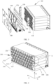
- FIG. 2 is a structural schematic diagram of a battery 100 in an embodiment of the present application.
- the battery 100 may include a plurality of battery cells 110, and the plurality of battery cells 110 are electrically connected.
- the battery 100 may further include a box body 120, the inside of the box body 120 is a hollow structure, and the plurality of battery cells 110 are accommodated in the box body 120.
- the box body 120 may include two parts, which are respectively called a first part 121 and a second part 122, and the first part 121 and the second part 122 are buckled together.
- Shapes of the first part 121 and the second part 122 may be determined by a combined shape of the plurality of battery cells 110, and each of the first part 121 and the second part 122 may have an opening.
- each of the first part 121 and the second part 122 may be a hollow cuboid and has only one surface as an open face, the opening of the first part 121 and the opening of the second part 122 are arranged oppositely, and the first part 121 and the second part 122 are buckled with each other to form a box body 120 with a closed chamber.
- the plurality of battery cells 110 are mutually combined in parallel or in series or in a mixed manner to be accommodated in the box body 120 formed after the first part 121 and the second part 122 are buckled.
- the number of the battery cells 110 may be set to any value.
- the plurality of battery cells 110 may be connected in series, in parallel or in a mixed manner to achieve higher capacity and power.
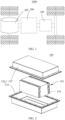
- FIG. 3 it is an exploded view of a battery module provided by an embodiment of the present application. Since the battery 100 may include a relatively large number of battery cells 110, for convenience of mounting, the battery cells 110 may be arranged in groups. As shown in FIG. 3 , each group of battery cells 110 form a battery module 101. The number of the battery cells 110 included in the battery module 101 is not limited and may be set as required.
- the battery 100 may include a plurality of battery modules 101, and these battery modules 101 may be connected in series or in parallel or in a mixed manner.
- the battery cell 110 includes one or a plurality of electrode assemblies (not shown in the figure), a shell 111 and a cover plate 112.
- the shell 111 and the cover plate 112 form an outer shell.
- a wall of the shell 111 and a wall of the cover plate 112 are both called a wall body of the battery cell 110.
- the shell 111 is determined according a shape after one or more electrode assemblies are combined.
- the shell 111 may be a hollow cuboid or cube or cylinder; and at least one surface of the shell 111 is provided with an opening, so that one or a plurality of electrode assemblies may be placed in the shell 111.
- one plane of the shell 111 is an open surface, that is, the plane is not provided with a wall body, so that the inside and the outside of the shell communicate with each other; and when the shell 111 is a hollow cylinder, an end face of the shell 111 is an open surface, that is, the end face is not provided with a wall body, so that the inside and the outside of the shell 111 communicate with each other.
- the cover plate 112 covers the opening and is connected to the shell 111 to form a closed cavity for placing the electrode assembly.
- the shell 111 is filled with electrolyte, such as dissolved electrolyte.
- the battery cell 110 may further include two electrode terminals 113, and the two electrode terminals 113 may be arranged on the cover plate 112.
- the cover plate 112 is flat plate shaped, the two electrode terminals 113 are fixed on the flat plate surface of the cover plate 112, and the two electrode terminals 113 are respectively regarded as a positive electrode terminal and a negative electrode terminal.
- Each electrode terminal 113 is correspondingly provided with a connecting component (not shown in the figure), or may also be called a current collecting component, which is located between the cover plate 112 and the electrode assembly and used to realize electrically connection of the electrode assembly and the electrode terminal 113.
- the battery 100 further includes an output electrode 150 and a mounting base 130.
- the output electrode 150 is a part for exporting electric energy of a plurality of battery cells 110.
- the mounting base 130 is configured to be mounted at at least one of the plurality of battery cells 110, for example, the mounting base 130 may be mounted at one of the battery cell 110, or the mounting base 130 may also be mounted at the plurality of battery cells 110.
- the mounting base 130 is used to fix the output electrode 150 of the battery 100 so as to ensure the position of the output electrode 150 is fixed.
- the battery 100 may be a battery module.
- the battery 100 may also be a battery pack, the battery pack includes one or a plurality of battery modules 101, and each battery module 101 is provided with two output electrodes 150.
- the two output electrodes 150 of the battery module 101 are respectively regarded as a positive output electrode and a negative output electrode, the positive output electrode and the negative output electrode may be located on the same side of the battery module 101, or may also be located on two sides of the battery module 101 (as shown in FIG. 4 ).
- each output electrode 150 corresponds to one of the mounting base 130, or one of the mounting base 130 may correspond to two output electrodes 150.
- the output electrode 150 is also used to be electrically connected to the adjacent battery module 101, and the output electrode 150 located on the end part of the battery module 101 is used to export the electric energy of the battery 100.
- the mounting base 130 is mounted at the battery cell 110, the battery cell 110 supports the mounting base 130, through the battery cell 100 to bear a twisting force generated when mounting the output electrode 150.
- the battery 100 on one hand, facilitates the mounting, saves parts and cost; and on another hand, reduces the space occupied by the mounting base 130, and increases the energy density of the battery 100.
- the plurality of battery cells 110 are fixed integrally through a bracket 140 or glue so as to ensure the compact structure of the battery module 101.
- the structure is compact and the energy density of the battery 100 is increased; and the mounting base 130 is located on an end part of an array formed by the plurality of battery cells 110, so the structural space is utilized reasonably.
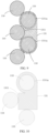
- the mounting base 130 is configured to be insertable into the gaps. It may be understood that after the plurality of battery cells 110 are assembled, there is a gap between two adjacent battery cells 110.
- the battery cell 110 is a cylindrical battery cell. After the plurality of battery cells 110 are assembled into the battery module 101, due to the contour shape of the cylindrical battery cell, there is a gap between two adjacent battery cells 110. Through the mounting base 130 inserting into the gaps among the plurality of battery cells 110, on one hand, the internal space of the battery 100 is reasonably utilized, extra space is prevented from being occupied, and the energy density of the battery 100 is increased; and on another hand, the cooperating surfaces between the mounting base 130 and the plurality of battery cells 110 are increased, so that the ability of the battery cell 110 of resisting the twisting force generated when the output electrode 150 is fixed at the mounting base 130 can be improved.
- X direction is an axis direction of the cylindrical battery cell
- a plurality of cylindrical battery cells are distributed in Y direction and Z direction, and there is a gap between two adjacent cylindrical battery cells, where the X direction, the Y direction and the Z direction are perpendicular to each other.
- the mounting base 130 is inserted into the gaps among the plurality of battery cells 110.
- the mounting base 130 may be inserted into the gaps among the plurality of battery cells 110 in different forms.
- the mounting base 130 may be inserted into the gaps from the end part of the battery cell 110 along an axis direction (X direction shown in FIG. 4 ) of the battery cell 110.
- FIG. 6 which is an assembling schematic diagram of a mounting base 130 and a battery cell 110 provided by another embodiment of the present application, the mounting base 130 may also be inserted into the gaps along a direction (Y direction shown in FIG.
- the axis direction of the battery cell 110 may be understood as a direction perpendicular to the cover plate 112 of the battery cell 110, which is the X direction in FIG. 4 .
- the mounting base 130 includes a substrate 131 and a connecting piece 132, the substrate 131 is used to mount the battery cell 110, and the connecting piece 132 is arranged in the substrate 131.
- the connecting piece 132 may be embedded into the substrate 131 after the substrate 131 is formed, or the connecting piece 132 may also be pre-embedded in the substrate 131.
- the connecting piece 132 is used to be connected to the output electrode 150 so as to fix the output electrode 150 at the substrate 131.
- the connecting piece 132 is located between two battery cells 110 so as to reduce occupied space.
- the substrate 131 may be an insulating piece, such as plastic (such as PVC (polyvinyl chloride), PE, PP and the like), thereby saving the manufacturing cost; and the connecting piece 132 is a conductive part, such as conductive metal (such as copper, other alloy and the like), which is used to realize electric connection between the output electrode 150 and an output electrode 150 of another battery module 101 or other conductive parts.
- plastic such as PVC (polyvinyl chloride), PE, PP and the like
- the connecting piece 132 is a conductive part, such as conductive metal (such as copper, other alloy and the like), which is used to realize electric connection between the output electrode 150 and an output electrode 150 of another battery module 101 or other conductive parts.
- the connecting piece 132 when the mounting base 130 and the cylindrical battery cell are assembled, due to the contour limitation of the cylindrical battery cell, there is a relatively large gap between two adjacent cylindrical battery cells, and the connecting piece 132 is located in the gap, so that the occupied space can be reduced and the energy density can be increased.
- the connecting piece 132 may be a nut.
- the output electrode 150 and the mounting base 130 are assembled, the output electrode 150 is connected to the nut through a screw or other threaded pieces, so that assembling and operating are facilitated, and conductive connection between the output electrode 150 and other parts can be realized.
- the output electrode 150 and the mounting base 130 are assembled, the output electrode 150 is fixed to the connecting piece 132 through the threaded piece (screw or bolt), and the threaded piece is in threaded connection with the connecting piece 132, that is, the output electrode 150 is fixed at the substrate 131 of the mounting base 130 through the threaded piece and the connecting piece 132. Through the cooperating mode of the threaded piece and the connecting piece 132, assembling and operating are facilitated.
- the output electrode 150 When the output electrode 150 is in conductive connection with other parts (the output electrode 150 of another battery module 101 or other conductive parts), through the match between the threaded piece and the connecting piece 132, the output electrode 150 and other parts are jointly fixed at the substrate 131 of the mounting base 130, that is, the output electrode 150 and other parts are clamped by the threaded piece and the connecting piece 132, and the output electrode 150 is in conductive connection with other parts.
- the threaded piece and the connecting piece 132 are both made of a conductive material.
- the output electrode 150 is connected to the connecting piece 132 through the threaded piece, to realize connection between the output electrode 150 and the mounting base 130. Since the mounting base 130 is supported by the battery cell 110, the twisting force generated when fixing the output electrode 150 through the threaded piece at the mounting base 130 is transmitted to the substrate 131 through the connecting piece 132, and is further transmitted to the battery cell 110 through the substrate 131, so that the battery cell 110 bears the twisting force generated when fixing the output electrode 150 at the mounting base 130 through the threaded piece.
- an outer surface of the connecting piece 132 and an outer surface of the substrate 131 are coplanar so as to ensure that the output electrode 150 and the substrate 131 have a larger contact area when the output electrode 150 is fixed at the connecting piece 132 through the threaded piece, that is, the substrate 131 has a larger supporting area towards the output electrode 150.
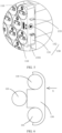
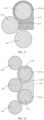
- FIG. 7 is an assembling schematic diagram of a limiting surface of a mounting base 130 and a battery cell 110 provided by an embodiment of the present application.
- the substrate 131 includes at least one limiting surface 1311, and the limiting surface 1311 is matched with the contour of the battery cell 110. It may be understood that the limiting surface 1311 is matched with the contour of a part of the battery cell 110 corresponding to the mounting base 130.
- the limiting surface 1311 may be an arc surface, and the limiting surface 1311 is matched with an external peripheral surface of the cylindrical battery cell 110; or when the rough contour of the battery cell 110 is a cuboid or a cube, the limiting surface 1311 may be a plane, and the limiting surface 1311 is matched with an external peripheral surface of the battery cell 110.
- the limiting surface 1311 may be attached to the battery cell 110, or there may be a gap between the limiting surface 1311 and the surface of the battery cell 110; and the limiting surface 1311 is used to realize positioning of the mounting base 130 when the mounting base 130 is being assembled with the battery cell 110.
- the mounting base 130 being mounted at the battery cell 110 is facilitated, to realize mounting positioning between the mounting base 130 and the battery 110, and limit the displacement of the mounting base 130; on another hand, space can be saved and the energy density can be increased.
- the limiting surface 1311 may be a flat plane, may also be an arc surface, or may further be a hole wall of a circular hole.
- the limiting surface 1311 is attached to the external peripheral surface of the battery cell 110. Since the limiting surface 1311 is matched with the contour of the battery cell 110, the limiting surface 1311 is attached to the external peripheral surface of the battery cell 110, and a better limitation of displacement of the mounting base 130 can be realized, so that the battery cell 110 can support the mounting base 130 when the output electrode 150 is connected to the mounting base 130.
- the at least one limiting surface 1311 may unconnected with the external peripheral surface of the battery cell 110, that is, there is a gap between the limiting surface 1311 and the battery cell 110, thereby facilitating the mounting guide of the mounting base 130. There is a movable space between the limiting surface 1311 and the battery cell 110 to adjust the position of the mounting base 130.
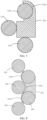
- FIG. 8 is an assembling schematic diagram of a limiting surface of the mounting base 130 and the battery cell 110 provided by another embodiment of the present application.
- two limiting surfaces 1311 are attached to the external peripheral surfaces of two cylindrical battery cells respectively, and there is a gap between one of the limiting surface 1311 and the battery cell 110.
- FIG. 9 is an assembling schematic diagram of a limiting surface of the mounting base 130 and the battery cell 110 provided by yet another embodiment of the present application. In FIG.
- two holes 1311a are sleeved on the external peripheral surfaces of the two battery cells 110 respectively, and there may be a gap between the holes 1311a and the corresponded battery cells 110, that is, the limiting surface 1311 includes an inner wall of the hole 1311a, and at last part of the inner wall of the hole 1311a is not in contact with the external peripheral surface of the battery cell 110.
- the outer surface of the mounting base 130 may also be provided with a limiting surface 1311 matching with other battery cells 110, which may be attached to the battery cell 110.
- the position of the mounting base 130 may be limited jointly through matching between a plurality of limiting surfaces 1311 and one of the battery cell 110 or a plurality of battery cells 110, so that the positioning requirement of the mounting base 130 is met, and the mounting strength of the mounting base 130 is improved.
- the external peripheral surface of the battery cell 110 refers to a surface of the battery cell 110 matching with the mounting base 130, it may be a surface of a shell 111 of the battery cell 110, or may also be a surface of the shell 111 of the battery cell 110 and a surface of the cover plate 112.
- the substrate 131 includes a plurality of limiting surfaces 1311, and the plurality of limiting surfaces 1311 are used to be attached to the external peripheral surfaces of the plurality of battery cells 110.
- the plurality of limiting surfaces 1311 are attached to the external peripheral surfaces of the plurality of battery cells 110, so that the mounting positioning surface of the mounting base 130 is increased, the mounting strength of the mounting base 130 is improved, and the twisting force generated when the output electrode 150 is mounted at the mounting base 130 is transmitted to the battery cell 110 more easily.
- FIG. 10 is a structural schematic diagram of a mounting base 130 provided by an embodiment of the present application.
- the substrate 131 includes a hole 1311a.
- the hole 1311a is used to be sleeved at the external peripheral surface of the battery cell 110.
- the hole 1311a is sleeved at the external peripheral surface of the battery cell 110, thereby facilitating the mounting positioning of the mounting base 130; and on another hand, the above solution can facilitate the mounting base 130 transmitting the twisting force to the battery cell 110.
- the hole 1311a when the battery cell 110 is a cylindrical battery cell, the hole 1311a may be a circular hole, and a hole wall of the circular hole is a limiting surface 1311; and when the battery cell 110 is a cubic battery cell, the hole 1311a may be a square hole, the square hole includes four planes, and each plane is a limiting surface 1311. A center line of the hole 1311a is parallel with the axis of the battery cell 110.
- the hole 1311a is sleeved at the external peripheral surface of the battery cell 110, which may be understood that the mounting base 130 is sleeved at the outer side of the battery cell 110, and the hole may be attached to the external peripheral surface of the battery cell 110 or may also not be attached to the external peripheral surface of the battery cell 110.
- FIG. 11 is a structural schematic diagram of a mounting base 130 provided by another embodiment of the present application.
- the substrate 131 when the battery cell 110 is a cylindrical battery cell and the substrate 131 includes one of the hole 1311a, in order to prevent the mounting base 130 from rotating relative to the battery cell 110, the substrate 131 further includes at least one limiting surface 1311 for being attached to the external peripheral surface of the adjacent battery cell 110, thereby positioning the mounting base 130.
- the limiting surface 1311 is attached to the external peripheral surface of the adjacent battery cell 110 corresponding to the hole 1311a, so that when the output electrode 150 is fixed at the connecting piece 132, rotation of the substrate 131 relative to the battery cell 110 can be limited, and the mounting base 130 can transmit the twisting force to the battery cell 110 more easily.
- the substrate 131 further includes a planar-shaped limiting surface 1311, the limiting surface 1311 is attached to the adjacent battery cell 110, and the position of the mounting base 130 is jointly limited by the limiting surface 1311 and the hole 1311a, thereby ensuring the positioning and supporting of the mounting base 130 by the battery cell 110.
- the substrate 131 further includes an arc-shaped limiting surface 1311, the contour of the limiting surface 1311 is matched with the contour of the external peripheral surface of the battery cell 110, the limiting surface 1311 is attached to the external peripheral surface of the adjacent battery cell 110, and the position of the mounting base 130 is jointly limited by the limiting surface 1311 and the hole 1311a.
- FIG. 12 is a structural schematic diagram of a mounting base 130 provided by yet another embodiment of the present application.
- the substrate 131 includes two holes 1311a, the two holes 1311a are used to be sleeved at the external peripheral surfaces of the two battery cells 110 respectively, and the two holes 1311a jointly limit the position of the mounting base 130. Since the two holes 1311a are sleeve at the external peripheral surfaces of the two battery cells 110 respectively, the ability of the battery cell 110 of resisting the twisting force generated when the output electrode 150 is fixed at the mounting base 130 can be improved, and at the same time, rotation of the substrate 131 relative to the battery cell 110 can be limited.
- the substrate 131 includes two circle-shaped holes 1311a which are symmetrically distributed, and the two holes 1311a correspond to two cylindrical battery cells 110 respectively.
- the two holes 1311a are respectively sleeved at the external peripheral surfaces of the two battery cells 110, and the hole walls of the holes 1311a are attached to the external peripheral surfaces of the battery cells 110.
- the two holes 1311a respectively correspond to two adjacent battery cells 110
- the connecting piece 132 is located between the two holes 1311a
- a geometric center line of the connecting piece 132 is perpendicular to a plane where center lines of the two holes 1311a are located.
- the substrate 131 When the output electrode 150 is connected to the connecting piece 132, the substrate 131 is stressed in a balanced manner, and the substrate 131 can be supported by two battery cells 110, so that the battery cells 110 can resist the twisting force generated when the output electrode 150 is mounted at the mounting base 130.
- the substrate 131 may further include an arc-shaped limiting surface 1311, the limiting surface 1311 is located between two circle-shaped holes 1311a, the limiting surface 1311 is matched with the contour of the battery cell 110, and the limiting surface 1311 is attached to the battery cell 110, so that the battery cell 110 supports the substrate 131 when the output electrode 150 is connected to the connecting piece 132.
- FIG. 13 is an assembling schematic diagram of a limiting portion 1313 of a mounting base 130 and a battery cell 110 provided by an embodiment of the present application.
- a limiting portion 1313 is formed on an end face of the substrate 131, and the limiting portion 1313 is used to be attached to an end part (a cover plate 112) of the battery cell 110 after the substrate 131 is mounted at the battery cell 110, so that the substrate 131 is limited in the axis direction of the battery cell 110, thereby limiting the further movement of the substrate 131 in the axis direction of the battery cell 110 and determining the position of the substrate 131.
- the end part of the battery cell 110 may be understood as a surface of the cover plate 112 where the electrode terminal 113 is located, and the electrode terminal 113 is located at the end part of the battery cell 110 and is protruded out of the cover plate 112.
- the end face of the substrate 131 may be understood as an end face of one end of the substrate 131 in the axis direction of the battery cell 110.
- the limiting portion 1313 is a bump, and the bump extends in a direction perpendicular to the axis direction of the battery cell 110 and is protruded out from the limiting surface 1311, thereby limiting the further movement of the mounting base 130 relative to the battery cell 110 in the axis direction of the battery cell 110 after the mounting base 130 is mounted at the battery cell 110.
- FIG. 14 is a structural schematic diagram of a limiting portion 1313 of a mounting base 130 provided by an embodiment of the present application. As shown in FIG. 14 , two limiting portions 1313 are arranged in the circumferential direction of the hole 1311a, and the two limiting portions 1313 are distributed symmetric about the center line of the hole 1311a.
- FIG. 15 is a structural schematic diagram of a limiting portion 1313 of a mounting base 130 provided by another embodiment of the present application.
- the limiting portion 1313 is of a plate-shaped structure.
- the mounting base 130 includes a hole
- the limiting portion 1313 covers the hole
- the limiting portion 1313 is provided with a through hole 1314 for the electrode terminal 113 to expose.
- the limiting portion 1313 is attached to the end part of the battery cell 110, and the electrode terminal 113 is exposed out from the hole, so that the electrode terminal 113 is connected to an electrode terminal 113 of the adjacent battery cell 110.
- FIG. 16 is an exploded view of a battery module 101 provided by another embodiment of the present application.
- the battery 100 further includes an isolating piece 160, and the isolating piece 160 may be an insulating piece for isolating the battery cell 110 from other parts (such as a harness); the isolating piece 160 is further used to realize the fixation of the harness (not shown in the figure), a confluence part (not shown in the figure); and when the battery 100 is assembled, the isolating piece 160 can also fix the battery cell 110.
- the isolating piece 160 is configured to be attached to one side of the limiting portion 1313 away from the battery cell 110.
- the isolating piece 160 is attached to the limiting portion 1313 to limit the limiting portion 1313 being located between the isolating piece 160 and the end part of the battery cell 110, so that the mounting stability of the mounting base 130 and the battery cell 110 is improved, and the risk of movement of the output electrode 150 is reduced.
- the output electrode 150 is fixed on the isolating piece 160, so that the mounting stability of the output electrode 150 is ensured.
- part of the output electrode 150 is located at the outer side of the edge of the isolating piece 160, facilitating connection between the output electrode 150 and the mounting base 130.
- the environmental temperature varies, which can affect the working state of the battery cell 110.
- the environmental temperature is relatively low, in order to ensure the normal work of the battery cell 110, it is necessary to heat the battery cell 110.
- FIG. 17 is a schematic diagram of a heating film 170 of a battery module 101 provided by an embodiment of the present application
- FIG. 18 is a schematic diagram of an avoiding portion of a mounting base provided by an embodiment of the present application.
- the battery 100 further includes a heating film 170, and the heating film 170 is used to heat the battery cell 110
- the mounting base 130 further includes an avoiding portion 1315, and the heating film 170 is configured to penetrate through the avoiding portion 1315 to heat the battery cell 110.
- the avoidance of the heating film 170 is realized by the avoiding portion 1315, thereby ensuring the heating film 170 can heat the battery cell 110, ensuring the heating effect, and improving the electrochemical property of the battery cell 110.
- the avoiding portion 1315 may be located at an end part of the substrate 131 which is provided with a limiting portion 1313, both the avoiding portion 1315 and the limiting portion 1313 are located at the end face of the substrate 131. It may be understood that the avoiding portion 1315 is a groove, that is, the end face of the substrate 131 is provided with a groove to form the avoiding portion 1315, and the remaining part of the end face forms the limiting portion 1313.
- the avoiding portion 1315 may also be a peripheral wall of the substrate 131. It may be understood that a groove is formed at the peripheral wall of the substrate 131 to form the avoiding portion 1315, and the heating film 170 penetrates through the avoiding portion 1315 to be in contact with the peripheral wall of the battery cell 110 to heat the battery cell 110.
- FIG. 19 is an enlarged view of a position B in FIG. 17 .
- the heating film 170 is provided with a first avoiding hole 171 and a second avoiding hole 172, the first avoiding hole 171 is used for the electrode terminal 113 of the battery cell 110 to penetrate through, the second avoiding hole 172 is used for the limiting portion 1313 to penetrate through, and the heating film 170 is used to heat the end part (cover plate 112) of the battery cell 110.
- the heating film 170 covers the mounting base 130, and the heating film 170 is attached to the end part of the battery cell 110 to heat the battery cell 110.
- the battery module 101 further includes an outer cover 180, and the outer cover 180 is used to fix the isolating piece 160 on the battery cell 110 to play a role in protecting the isolating piece 160, the harness and the battery cell 110.
- the battery module 101 further includes a protective cover (not shown in the figure), the substrate 131 of the mounting base 130 is provided with two supporting arms 133, the two supporting arms 133 are symmetrically distributed on two sides of the connecting piece 132, an accommodating space between the two supporting arms 133 is limited for accommodating the protective cover, a clamping groove 1331 matched with the protective cover is formed at each supporting arm 133, the protective cover is configured to be buckled with the clamping groove 1331, and the protective cover is used to protect and isolate the output electrode.
- a protective cover (not shown in the figure)
- the substrate 131 of the mounting base 130 is provided with two supporting arms 133, the two supporting arms 133 are symmetrically distributed on two sides of the connecting piece 132, an accommodating space between the two supporting arms 133 is limited for accommodating the protective cover, a clamping groove 1331 matched with the protective cover is formed at each supporting arm 133, the protective cover is configured to be buckled with the clamping groove 1331, and the protective cover is used to protect and isolate the output electrode.
- An embodiment of the present application further provides an electric apparatus.
- the electric apparatus may include the battery cell 110 in the aforementioned embodiments.
- the electric apparatus may be a vehicle 1000, a ship or spacecraft.
- the battery 100 and the electric apparatus in the embodiments of the present application are described above.
- a manufacturing method of the battery 100 according to the embodiments of the present application will be described below.
- the parts which are not described in detail may be referenced from the aforementioned embodiments.
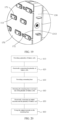
- FIG. 20 is a schematic flowchart of a manufacturing method of a battery 100 provided by an embodiment of the present application.
- the method may include: 410, providing a plurality of battery cells 110; 420, electrically connecting the plurality of battery cells 110; 430, providing a mounting base 130; 440, mounting the mounting base 130 on at least one of the plurality of battery cells 110; 450, electrically connecting an output electrode 150 and the plurality of battery cells 110, so that the output electrode 150 can export electric energy of the plurality of battery cells 110; and 460, fixing the output electrode 150 on the mounting base 130.
- FIG. 21 shows a schematic flowchart of a manufacturing method of a battery 100 provided by another embodiment of the present application.
- the method may include: 410, providing a plurality of battery cells 110; 420, electrically connecting the plurality of battery cells 110; 430, providing a mounting base 130; 440, mounting the mounting base 130 on at least one of the plurality of battery cells 110; 450, fixing the output electrode 150 on the mounting base 130; and 460, electrically connecting the output electrode 150 and the plurality of battery cells 110, so that the output electrode 150 can export electric energy of the plurality of battery cells 110.
- FIG. 22 is a schematic flowchart of a manufacturing method of a battery 100 provided by yet another embodiment of the present application.
- the method may include: 410, providing a plurality of battery cells 110; 420, electrically connecting the plurality of battery cells 110; 430, providing a mounting base 130, where the mounting base 130 includes at least one limiting surface 1311, and the limiting surface 1311 is matched with the contour of the battery cell 110; 440, providing an output electrode 150; 450, electrically connecting the output electrode 150 and the plurality of battery cells 110, so that the output electrode 150 can export electric energy of the plurality of battery cells 110; and 460, fixing the output electrode 150 on the mounting base 130.
Landscapes
- Chemical & Material Sciences (AREA)
- Chemical Kinetics & Catalysis (AREA)
- Electrochemistry (AREA)
- General Chemical & Material Sciences (AREA)
- Engineering & Computer Science (AREA)
- Manufacturing & Machinery (AREA)
- Aviation & Aerospace Engineering (AREA)
- Materials Engineering (AREA)
- Battery Mounting, Suspending (AREA)
Claims (11)
- Batteriemodul (101), umfassend:mehrere Batteriezellen (110), wobei die mehreren Batteriezellen (110) elektrisch verbunden sind;zwei Ausgangselektroden (150), die dazu verwendet werden, elektrische Energie der mehreren Batteriezellen (110) abzugeben; undeine Befestigungsbasis (130), die dazu verwendet wird, eine der zwei Ausgangselektroden (150) des Batteriemoduls (101) zu befestigen, wobei die Befestigungsbasis (130) wenigstens eine Begrenzungsfläche (1311) umfasst, die Begrenzungsfläche (1311) auf die Kontur der Batteriezelle (110) abgestimmt ist und die Befestigungsbasis (130) an einem Teil der Batteriezellen (110) der mehreren Batteriezellen (110) befestigt ist;wobei die Befestigungsbasis (130) ein Substrat (131) und ein Verbindungsstück (132) umfasst, wobei das Verbindungsstück (132) in dem Substrat (131) angeordnet ist, das Verbindungsstück (132) dazu verwendet wird, über ein Gewindestück mit der Ausgangselektrode (150) verbunden zu werden, um die Ausgangselektrode (150) an dem Substrat (131) zu befestigen, das Verbindungsstück (132) sich zwischen den zwei Batteriezellen (110) befindet und das Verbindungsstück (132) ein leitfähiges Teil ist; undwobei das Substrat (131) zwei kreisförmige Löcher (1311a) umfasst, die symmetrisch verteilt sind, und die zwei kreisförmigen Löcher (1311a) jeweils einer von zwei zylindrischen Batteriezellen (110) entsprechen, wenn das Substrat (131) an wenigstens einer der mehreren Batteriezellen (110) befestigt ist, die zwei kreisförmigen Löcher (1311a) jeweils auf äußere Umfangsflächen der zwei zylindrischen Batteriezellen (110) aufgeschoben sind, das Verbindungsstück (132) sich zwischen den zwei kreisförmigen Löchern (1311a) befindet und eine geometrische Mittellinie des Verbindungsstücks (132) senkrecht zu einer Ebene verläuft, in der sich Mittellinien der zwei kreisförmigen Löcher (1311a) befinden.
- Batteriemodul (101) nach Anspruch 1, wobei die Begrenzungsfläche (1311) dazu verwendet wird, an einer äußeren Umfangsfläche der Batteriezelle (110) angebracht zu werden.
- Batteriemodul (101) nach Anspruch 1 oder 2, wobei die Befestigungsbasis (130) mehrere Begrenzungsflächen (1311) umfasst und die mehreren Begrenzungsflächen (1311) dazu verwendet werden, an äußeren Umfangsflächen der mehreren Batteriezellen (110) angebracht zu werden.
- Batteriemodul (101) nach einem der Ansprüche 1-3, wobei zwischen den mehreren Batteriezellen (110) Spalte vorhanden sind und die Befestigungsbasis (130) dazu ausgestaltet ist, in die Spalte einsetzbar zu sein.
- Batteriemodul (101) nach einem der Ansprüche 1-4, wobei das Verbindungsstück (132) eine Mutter ist und die Mutter mit einem Gewindestück verbunden wird, um die Ausgangselektrode (150) an der Befestigungsbasis (130) zu befestigen.
- Batteriemodul (101) nach einem der Ansprüche 1-5, wobei an einer Endfläche der Befestigungsbasis (130) ein Begrenzungsabschnitt (1313) ausgebildet ist und der Begrenzungsabschnitt (1313) dazu verwendet wird, an einem Endteil der Batteriezelle (110) angebracht zu werden.
- Batteriemodul (101) nach Anspruch 6, wobei das Batteriemodul (101) ferner ein Isolierstück (160) umfasst, wobei das Isolierstück (160) dazu ausgestaltet ist, an einer Seite des Begrenzungsabschnitts (1313), weg von der Batteriezelle (110), angebracht zu werden.
- Batteriemodul (101) nach Anspruch 6, wobei das Batteriemodul (101) ferner eine Heizfolie (170) umfasst, wobei die Befestigungsbasis (130) ferner einen Umgehungsabschnitt (1315) umfasst und die Heizfolie (170) dazu ausgestaltet ist, den Umgehungsabschnitt (1315) zu durchdringen, um die Batteriezelle (110) zu erwärmen.
- Batterie (100), die das Batteriemodul (101) nach einem der Ansprüche 1-8 umfasst.
- Elektrisches Gerät, das die Batterie (100) nach Anspruch 9 umfasst.
- Herstellungsverfahren für ein Batteriemodul (101), das dazu ausgestaltet ist, das Batteriemodul (101) nach einem der Ansprüche 1-10 herzustellen, wobei das Verfahren Folgendes umfasst:Bereitstellen mehrerer Batteriezellen (110);elektrisches Verbinden der mehreren Batteriezellen (110);Bereitstellen einer Befestigungsbasis (130), wobei die Befestigungsbasis (130) wenigstens eine Begrenzungsfläche (1311) umfasst, die Begrenzungsfläche (1311) auf die Kontur der Batteriezelle (110) abgestimmt ist und die Befestigungsbasis (130) an einem Teil der Batteriezellen (110) der mehreren Batteriezellen (110) befestigt ist; und wobei die Befestigungsbasis (130) ein Substrat (131) und ein Verbindungsstück (132) umfasst, wobei das Verbindungsstück (132) in dem Substrat (131) angeordnet ist, das Verbindungsstück (132) dazu verwendet wird, mit der Ausgangselektrode (150) verbunden zu werden, um die Ausgangselektrode (150) an dem Substrat (131) zu befestigen, das Verbindungsstück (132) sich zwischen den zwei Batteriezellen (110) befindet und das Verbindungsstück (132) ein leitfähiges Teil ist;Bereitstellen von zwei Ausgangselektroden (150);elektrisches Verbinden der Ausgangselektrode (150) mit den mehreren Batteriezellen (110), sodass die Ausgangselektrode (150) in der Lage ist, elektrische Energie der mehreren Batteriezellen (110) abzugeben; undBefestigen einer der zwei Ausgangselektroden (150) an der Befestigungsbasis (130), wobei das Substrat (131) zwei kreisförmige Löcher (1311a) umfasst, die symmetrisch verteilt sind, und die zwei kreisförmigen Löcher (1311a) jeweils einer von zwei zylindrischen Batteriezellen (110) entsprechen, wenn das Substrat (131) an wenigstens einer der mehreren Batteriezellen (110) befestigt ist, die zwei kreisförmigen Löcher (1311a) jeweils auf äußere Umfangsflächen der zwei zylindrischen Batteriezellen (110) aufgeschoben sind, das Verbindungsstück (132) sich zwischen den zwei kreisförmigen Löchern (1311a) befindet und eine geometrische Mittellinie des Verbindungsstücks (132) senkrecht zu einer Ebene verläuft, in der sich Mittellinien der zwei kreisförmigen Löcher (1311a) befinden.
Applications Claiming Priority (2)
| Application Number | Priority Date | Filing Date | Title |
|---|---|---|---|
| CN202011377701.9A CN112259872B (zh) | 2020-12-01 | 2020-12-01 | 电池、用电设备及电池的制造方法 |
| PCT/CN2021/091333 WO2022116473A1 (zh) | 2020-12-01 | 2021-04-30 | 电池、用电设备及电池的制造方法 |
Publications (4)
| Publication Number | Publication Date |
|---|---|
| EP4044347A1 EP4044347A1 (de) | 2022-08-17 |
| EP4044347A4 EP4044347A4 (de) | 2022-10-26 |
| EP4044347C0 EP4044347C0 (de) | 2025-03-19 |
| EP4044347B1 true EP4044347B1 (de) | 2025-03-19 |
Family
ID=81751864
Family Applications (1)
| Application Number | Title | Priority Date | Filing Date |
|---|---|---|---|
| EP21820074.9A Active EP4044347B1 (de) | 2020-12-01 | 2021-04-30 | Batterie, elektrische vorrichtung und herstellungsverfahren für eine batterie |
Country Status (4)
| Country | Link |
|---|---|
| US (1) | US12315945B2 (de) |
| EP (1) | EP4044347B1 (de) |
| CN (1) | CN221057553U (de) |
| ES (1) | ES3031050T3 (de) |
Family Cites Families (11)
| Publication number | Priority date | Publication date | Assignee | Title |
|---|---|---|---|---|
| US20120301762A1 (en) | 2011-05-25 | 2012-11-29 | Imageworks Display And Marketing Group | Modular dry cell battery pack |
| CN205488273U (zh) | 2016-01-18 | 2016-08-17 | 武汉闪信鼎中新能源有限公司 | 一种电池组并联连接装置 |
| CN205609613U (zh) * | 2016-03-25 | 2016-09-28 | 深圳市沃特玛电池有限公司 | 一种动力电池模组 |
| US20180069212A1 (en) | 2016-09-07 | 2018-03-08 | Thunder Power New Energy Vehicle Development Company Limited | Battery system housing with bonded rib fixation |
| CN106785215A (zh) * | 2017-01-17 | 2017-05-31 | 华霆(合肥)动力技术有限公司 | 一种电池模组及动力电池 |
| CN107154478A (zh) * | 2017-05-26 | 2017-09-12 | 江苏银基烯碳能源科技有限公司 | 一种电池模组 |
| CN108198983B (zh) * | 2018-02-24 | 2024-03-08 | 华霆(合肥)动力技术有限公司 | 电池模组及电池系统 |
| CN108258168A (zh) | 2018-03-21 | 2018-07-06 | 湖南金杯新能源发展有限公司 | 方形电芯模组 |
| KR102757688B1 (ko) | 2019-01-28 | 2025-01-21 | 삼성에스디아이 주식회사 | 배터리 팩 |
| CN111952515B (zh) | 2020-10-19 | 2021-02-02 | 江苏时代新能源科技有限公司 | 电池、用电装置、制备电池的方法及装置 |
| CN112259872B (zh) | 2020-12-01 | 2021-06-04 | 江苏时代新能源科技有限公司 | 电池、用电设备及电池的制造方法 |
-
2021
- 2021-04-30 EP EP21820074.9A patent/EP4044347B1/de active Active
- 2021-04-30 CN CN202190000864.7U patent/CN221057553U/zh active Active
- 2021-04-30 ES ES21820074T patent/ES3031050T3/es active Active
- 2021-12-28 US US17/563,515 patent/US12315945B2/en active Active
Also Published As
| Publication number | Publication date |
|---|---|
| ES3031050T3 (en) | 2025-07-03 |
| EP4044347A1 (de) | 2022-08-17 |
| EP4044347C0 (de) | 2025-03-19 |
| CN221057553U (zh) | 2024-05-31 |
| US20220173468A1 (en) | 2022-06-02 |
| EP4044347A4 (de) | 2022-10-26 |
| US12315945B2 (en) | 2025-05-27 |
Similar Documents
| Publication | Publication Date | Title |
|---|---|---|
| CN113300037B (zh) | 电池、用电设备及电池的制造方法 | |
| CN219017811U (zh) | 电池和用电设备 | |
| US20220352573A1 (en) | Battery cell, battery, power consumption device, and battery manufacturing method and device | |
| US20250105474A1 (en) | Battery cell, battery, and electric apparatus | |
| US20250192375A1 (en) | Battery and electrical apparatus | |
| EP4050711A1 (de) | Enddeckelanordnung, batteriezelle, batterie und verfahren und vorrichtung zum herstellen einer batteriezelle | |
| WO2023133859A1 (zh) | 电池单体及其制造方法、设备、电池及用电装置 | |
| KR20230129053A (ko) | 배터리, 전기 장치, 배터리 제조 방법 및 장치 | |
| CN117136466A (zh) | 电池单体及其制造方法和设备、电池以及用电装置 | |
| EP4468485A1 (de) | Batteriezelle, batteriemodul, batterie und stromverbrauchende vorrichtung | |
| US20250096442A1 (en) | Battery cell, battery, and electric apparatus | |
| WO2023155211A1 (zh) | 电池、用电设备、制备电池的方法和设备 | |
| US20250030126A1 (en) | Battery cell, battery and electric device | |
| EP4044347B1 (de) | Batterie, elektrische vorrichtung und herstellungsverfahren für eine batterie | |
| US20240006702A1 (en) | Battery and electrical apparatus | |
| US20230268601A1 (en) | Battery, power consumption device, and method and device for producing battery | |
| EP4258437A1 (de) | Batterie, elektrische vorrichtung sowie batterieherstellungsverfahren und -vorrichtung | |
| EP4037087B1 (de) | Äquipotenzialvorrichtung, äquipotenzialstruktur, batterie und energieverbrauchsvorrichtung | |
| CN116706409A (zh) | 电池及其制造方法和制造系统、用电装置 | |
| KR20230087530A (ko) | 배터리 셀, 배터리, 장치, 배터리 셀의 제조 방법 및 제조 설비 | |
| US12407069B2 (en) | Battery cell, battery, and electrical device | |
| US20250096433A1 (en) | Battery cell, battery and electricity consumption device | |
| US20250337082A1 (en) | Battery cell, battery, power consumption device and manufacturing device and method for battery cell | |
| US20240258618A1 (en) | Battery cell, battery, power consumption apparatus, and method and apparatus for preparing battery | |
| US20240266694A1 (en) | Electrode terminal, pole assembly, battery, and electric device |
Legal Events
| Date | Code | Title | Description |
|---|---|---|---|
| STAA | Information on the status of an ep patent application or granted ep patent |
Free format text: STATUS: UNKNOWN |
|
| STAA | Information on the status of an ep patent application or granted ep patent |
Free format text: STATUS: THE INTERNATIONAL PUBLICATION HAS BEEN MADE |
|
| PUAI | Public reference made under article 153(3) epc to a published international application that has entered the european phase |
Free format text: ORIGINAL CODE: 0009012 |
|
| STAA | Information on the status of an ep patent application or granted ep patent |
Free format text: STATUS: REQUEST FOR EXAMINATION WAS MADE |
|
| 17P | Request for examination filed |
Effective date: 20211216 |
|
| AK | Designated contracting states |
Kind code of ref document: A1 Designated state(s): AL AT BE BG CH CY CZ DE DK EE ES FI FR GB GR HR HU IE IS IT LI LT LU LV MC MK MT NL NO PL PT RO RS SE SI SK SM TR |
|
| A4 | Supplementary search report drawn up and despatched |
Effective date: 20220928 |
|
| RIC1 | Information provided on ipc code assigned before grant |
Ipc: H01M 50/213 20210101AFI20220922BHEP |
|
| STAA | Information on the status of an ep patent application or granted ep patent |
Free format text: STATUS: EXAMINATION IS IN PROGRESS |
|
| 17Q | First examination report despatched |
Effective date: 20231025 |
|
| DAV | Request for validation of the european patent (deleted) | ||
| DAX | Request for extension of the european patent (deleted) | ||
| GRAP | Despatch of communication of intention to grant a patent |
Free format text: ORIGINAL CODE: EPIDOSNIGR1 |
|
| STAA | Information on the status of an ep patent application or granted ep patent |
Free format text: STATUS: GRANT OF PATENT IS INTENDED |
|
| INTG | Intention to grant announced |
Effective date: 20250102 |
|
| RIN1 | Information on inventor provided before grant (corrected) |
Inventor name: QIAN, MU Inventor name: JI, JINQING Inventor name: QIN, FENG Inventor name: WANG, PENG Inventor name: WANG, YONGGUANG |
|
| GRAS | Grant fee paid |
Free format text: ORIGINAL CODE: EPIDOSNIGR3 |
|
| GRAA | (expected) grant |
Free format text: ORIGINAL CODE: 0009210 |
|
| STAA | Information on the status of an ep patent application or granted ep patent |
Free format text: STATUS: THE PATENT HAS BEEN GRANTED |
|
| AK | Designated contracting states |
Kind code of ref document: B1 Designated state(s): AL AT BE BG CH CY CZ DE DK EE ES FI FR GB GR HR HU IE IS IT LI LT LU LV MC MK MT NL NO PL PT RO RS SE SI SK SM TR |
|
| REG | Reference to a national code |
Ref country code: GB Ref legal event code: FG4D |
|
| REG | Reference to a national code |
Ref country code: CH Ref legal event code: EP |
|
| REG | Reference to a national code |
Ref country code: DE Ref legal event code: R096 Ref document number: 602021027898 Country of ref document: DE |
|
| REG | Reference to a national code |
Ref country code: IE Ref legal event code: FG4D |
|
| U01 | Request for unitary effect filed |
Effective date: 20250411 |
|
| U07 | Unitary effect registered |
Designated state(s): AT BE BG DE DK EE FI FR IT LT LU LV MT NL PT RO SE SI Effective date: 20250422 |
|
| U20 | Renewal fee for the european patent with unitary effect paid |
Year of fee payment: 5 Effective date: 20250422 |
|
| REG | Reference to a national code |
Ref country code: ES Ref legal event code: FG2A Ref document number: 3031050 Country of ref document: ES Kind code of ref document: T3 Effective date: 20250703 |
|
| PG25 | Lapsed in a contracting state [announced via postgrant information from national office to epo] |
Ref country code: RS Free format text: LAPSE BECAUSE OF FAILURE TO SUBMIT A TRANSLATION OF THE DESCRIPTION OR TO PAY THE FEE WITHIN THE PRESCRIBED TIME-LIMIT Effective date: 20250619 |
|
| PGFP | Annual fee paid to national office [announced via postgrant information from national office to epo] |
Ref country code: GB Payment date: 20250417 Year of fee payment: 5 Ref country code: ES Payment date: 20250506 Year of fee payment: 5 |
|
| PG25 | Lapsed in a contracting state [announced via postgrant information from national office to epo] |
Ref country code: NO Free format text: LAPSE BECAUSE OF FAILURE TO SUBMIT A TRANSLATION OF THE DESCRIPTION OR TO PAY THE FEE WITHIN THE PRESCRIBED TIME-LIMIT Effective date: 20250619 |
|
| PG25 | Lapsed in a contracting state [announced via postgrant information from national office to epo] |
Ref country code: HR Free format text: LAPSE BECAUSE OF FAILURE TO SUBMIT A TRANSLATION OF THE DESCRIPTION OR TO PAY THE FEE WITHIN THE PRESCRIBED TIME-LIMIT Effective date: 20250319 |
|
| PG25 | Lapsed in a contracting state [announced via postgrant information from national office to epo] |
Ref country code: GR Free format text: LAPSE BECAUSE OF FAILURE TO SUBMIT A TRANSLATION OF THE DESCRIPTION OR TO PAY THE FEE WITHIN THE PRESCRIBED TIME-LIMIT Effective date: 20250620 |
|
| PGFP | Annual fee paid to national office [announced via postgrant information from national office to epo] |
Ref country code: HU Payment date: 20250320 Year of fee payment: 5 |
|
| REG | Reference to a national code |
Ref country code: HU Ref legal event code: AG4A Ref document number: E071792 Country of ref document: HU |
|
| PG25 | Lapsed in a contracting state [announced via postgrant information from national office to epo] |
Ref country code: SM Free format text: LAPSE BECAUSE OF FAILURE TO SUBMIT A TRANSLATION OF THE DESCRIPTION OR TO PAY THE FEE WITHIN THE PRESCRIBED TIME-LIMIT Effective date: 20250319 |
|
| PG25 | Lapsed in a contracting state [announced via postgrant information from national office to epo] |
Ref country code: PL Free format text: LAPSE BECAUSE OF FAILURE TO SUBMIT A TRANSLATION OF THE DESCRIPTION OR TO PAY THE FEE WITHIN THE PRESCRIBED TIME-LIMIT Effective date: 20250319 |
|
| PG25 | Lapsed in a contracting state [announced via postgrant information from national office to epo] |
Ref country code: CZ Free format text: LAPSE BECAUSE OF FAILURE TO SUBMIT A TRANSLATION OF THE DESCRIPTION OR TO PAY THE FEE WITHIN THE PRESCRIBED TIME-LIMIT Effective date: 20250319 |
|
| PG25 | Lapsed in a contracting state [announced via postgrant information from national office to epo] |
Ref country code: SK Free format text: LAPSE BECAUSE OF FAILURE TO SUBMIT A TRANSLATION OF THE DESCRIPTION OR TO PAY THE FEE WITHIN THE PRESCRIBED TIME-LIMIT Effective date: 20250319 |
|
| PG25 | Lapsed in a contracting state [announced via postgrant information from national office to epo] |
Ref country code: IS Free format text: LAPSE BECAUSE OF FAILURE TO SUBMIT A TRANSLATION OF THE DESCRIPTION OR TO PAY THE FEE WITHIN THE PRESCRIBED TIME-LIMIT Effective date: 20250719 |
|
| REG | Reference to a national code |
Ref country code: CH Ref legal event code: H13 Free format text: ST27 STATUS EVENT CODE: U-0-0-H10-H13 (AS PROVIDED BY THE NATIONAL OFFICE) Effective date: 20251125 |