EP4043902A1 - Mrt-bildgebung mit wasser/fett-trennung nach dixon-verfahren - Google Patents
Mrt-bildgebung mit wasser/fett-trennung nach dixon-verfahren Download PDFInfo
- Publication number
- EP4043902A1 EP4043902A1 EP21156561.9A EP21156561A EP4043902A1 EP 4043902 A1 EP4043902 A1 EP 4043902A1 EP 21156561 A EP21156561 A EP 21156561A EP 4043902 A1 EP4043902 A1 EP 4043902A1
- Authority
- EP
- European Patent Office
- Prior art keywords
- magnetic field
- acquisition
- echo
- pulses
- imaging
- Prior art date
- Legal status (The legal status is an assumption and is not a legal conclusion. Google has not performed a legal analysis and makes no representation as to the accuracy of the status listed.)
- Withdrawn
Links
Images
Classifications
-
- G—PHYSICS
- G01—MEASURING; TESTING
- G01R—MEASURING ELECTRIC VARIABLES; MEASURING MAGNETIC VARIABLES
- G01R33/00—Arrangements or instruments for measuring magnetic variables
- G01R33/20—Arrangements or instruments for measuring magnetic variables involving magnetic resonance
- G01R33/44—Arrangements or instruments for measuring magnetic variables involving magnetic resonance using nuclear magnetic resonance [NMR]
- G01R33/48—NMR imaging systems
- G01R33/4828—Resolving the MR signals of different chemical species, e.g. water-fat imaging
-
- G—PHYSICS
- G01—MEASURING; TESTING
- G01R—MEASURING ELECTRIC VARIABLES; MEASURING MAGNETIC VARIABLES
- G01R33/00—Arrangements or instruments for measuring magnetic variables
- G01R33/20—Arrangements or instruments for measuring magnetic variables involving magnetic resonance
- G01R33/28—Details of apparatus provided for in groups G01R33/44 - G01R33/64
- G01R33/38—Systems for generation, homogenisation or stabilisation of the main or gradient magnetic field
- G01R33/385—Systems for generation, homogenisation or stabilisation of the main or gradient magnetic field using gradient magnetic field coils
-
- G—PHYSICS
- G01—MEASURING; TESTING
- G01R—MEASURING ELECTRIC VARIABLES; MEASURING MAGNETIC VARIABLES
- G01R33/00—Arrangements or instruments for measuring magnetic variables
- G01R33/20—Arrangements or instruments for measuring magnetic variables involving magnetic resonance
- G01R33/44—Arrangements or instruments for measuring magnetic variables involving magnetic resonance using nuclear magnetic resonance [NMR]
- G01R33/48—NMR imaging systems
- G01R33/50—NMR imaging systems based on the determination of relaxation times, e.g. T1 measurement by IR sequences; T2 measurement by multiple-echo sequences
-
- G—PHYSICS
- G01—MEASURING; TESTING
- G01R—MEASURING ELECTRIC VARIABLES; MEASURING MAGNETIC VARIABLES
- G01R33/00—Arrangements or instruments for measuring magnetic variables
- G01R33/20—Arrangements or instruments for measuring magnetic variables involving magnetic resonance
- G01R33/44—Arrangements or instruments for measuring magnetic variables involving magnetic resonance using nuclear magnetic resonance [NMR]
- G01R33/48—NMR imaging systems
- G01R33/54—Signal processing systems, e.g. using pulse sequences ; Generation or control of pulse sequences; Operator console
- G01R33/543—Control of the operation of the MR system, e.g. setting of acquisition parameters prior to or during MR data acquisition, dynamic shimming, use of one or more scout images for scan plane prescription
-
- G—PHYSICS
- G01—MEASURING; TESTING
- G01R—MEASURING ELECTRIC VARIABLES; MEASURING MAGNETIC VARIABLES
- G01R33/00—Arrangements or instruments for measuring magnetic variables
- G01R33/20—Arrangements or instruments for measuring magnetic variables involving magnetic resonance
- G01R33/44—Arrangements or instruments for measuring magnetic variables involving magnetic resonance using nuclear magnetic resonance [NMR]
- G01R33/48—NMR imaging systems
- G01R33/54—Signal processing systems, e.g. using pulse sequences ; Generation or control of pulse sequences; Operator console
- G01R33/56—Image enhancement or correction, e.g. subtraction or averaging techniques, e.g. improvement of signal-to-noise ratio and resolution
- G01R33/5608—Data processing and visualization specially adapted for MR, e.g. for feature analysis and pattern recognition on the basis of measured MR data, segmentation of measured MR data, edge contour detection on the basis of measured MR data, for enhancing measured MR data in terms of signal-to-noise ratio by means of noise filtering or apodization, for enhancing measured MR data in terms of resolution by means for deblurring, windowing, zero filling, or generation of gray-scaled images, colour-coded images or images displaying vectors instead of pixels
-
- G—PHYSICS
- G01—MEASURING; TESTING
- G01R—MEASURING ELECTRIC VARIABLES; MEASURING MAGNETIC VARIABLES
- G01R33/00—Arrangements or instruments for measuring magnetic variables
- G01R33/20—Arrangements or instruments for measuring magnetic variables involving magnetic resonance
- G01R33/44—Arrangements or instruments for measuring magnetic variables involving magnetic resonance using nuclear magnetic resonance [NMR]
- G01R33/48—NMR imaging systems
- G01R33/54—Signal processing systems, e.g. using pulse sequences ; Generation or control of pulse sequences; Operator console
- G01R33/56—Image enhancement or correction, e.g. subtraction or averaging techniques, e.g. improvement of signal-to-noise ratio and resolution
- G01R33/561—Image enhancement or correction, e.g. subtraction or averaging techniques, e.g. improvement of signal-to-noise ratio and resolution by reduction of the scanning time, i.e. fast acquiring systems, e.g. using echo-planar pulse sequences
- G01R33/5615—Echo train techniques involving acquiring plural, differently encoded, echo signals after one RF excitation, e.g. using gradient refocusing in echo planar imaging [EPI], RF refocusing in rapid acquisition with relaxation enhancement [RARE] or using both RF and gradient refocusing in gradient and spin echo imaging [GRASE]
- G01R33/5617—Echo train techniques involving acquiring plural, differently encoded, echo signals after one RF excitation, e.g. using gradient refocusing in echo planar imaging [EPI], RF refocusing in rapid acquisition with relaxation enhancement [RARE] or using both RF and gradient refocusing in gradient and spin echo imaging [GRASE] using RF refocusing, e.g. RARE
-
- G—PHYSICS
- G01—MEASURING; TESTING
- G01R—MEASURING ELECTRIC VARIABLES; MEASURING MAGNETIC VARIABLES
- G01R33/00—Arrangements or instruments for measuring magnetic variables
- G01R33/20—Arrangements or instruments for measuring magnetic variables involving magnetic resonance
- G01R33/44—Arrangements or instruments for measuring magnetic variables involving magnetic resonance using nuclear magnetic resonance [NMR]
- G01R33/48—NMR imaging systems
- G01R33/54—Signal processing systems, e.g. using pulse sequences ; Generation or control of pulse sequences; Operator console
- G01R33/56—Image enhancement or correction, e.g. subtraction or averaging techniques, e.g. improvement of signal-to-noise ratio and resolution
- G01R33/565—Correction of image distortions, e.g. due to magnetic field inhomogeneities
- G01R33/56518—Correction of image distortions, e.g. due to magnetic field inhomogeneities due to eddy currents, e.g. caused by switching of the gradient magnetic field
Definitions
- the invention relates to the field of magnetic resonance (MR) imaging. It concerns a method of MR imaging of an object placed in the examination volume of an MR device.
- the invention also relates to an MR device and to a computer program to be run on an MR device.
- Image-forming MR methods which utilize the interaction between magnetic fields and nuclear spins in order to form two-dimensional or three-dimensional images are widely used nowadays, notably in the field of medical diagnostics, because for the imaging of soft tissue they are superior to other imaging methods in many respects, do not require ionizing radiation and are usually not invasive.
- the body of the patient to be examined is arranged in a strong, uniform magnetic field B 0 whose direction at the same time defines an axis (normally the z-axis) of the co-ordinate system on which the measurement is based.
- the magnetic field B 0 produces different energy levels for the individual nuclear spins in dependence on the magnetic field strength which can be excited (spin resonance) by application of an electromagnetic field (RF field) of defined frequency (Larmor frequency) in the radiofrequency range.
- the distribution of the individual nuclear spins produces an overall magnetization which can be deflected out of the state of equilibrium by application of an electromagnetic pulse of appropriate frequency (RF pulse) perpendicular to the z-axis, so that the magnetization performs a precessional motion about the z-axis.
- the precessional motion describes a surface of a cone whose angle of aperture is referred to as flip angle.
- the magnitude of the flip angle is dependent on the strength and the duration of the applied electromagnetic pulse.
- 90° pulse the spins are deflected from the z-axis to the transverse plane (90° flip angle).
- the magnetization relaxes back to the original state of equilibrium, in which the magnetization in the z direction is built up again with a first time constant T 1 (spin-lattice or longitudinal relaxation time), and the magnetization in the direction perpendicular to the z direction relaxes with a second time constant T 2 (spin-spin or transverse relaxation time).
- T 1 spin-lattice or longitudinal relaxation time
- T 2 spin-spin or transverse relaxation time
- the decay of the transverse magnetization is accompanied, after application of, for example, a 90° pulse, by a transition of the nuclear spins (induced by local magnetic field inhomogeneities) from an ordered state with the same phase to a state in which the phase is uniformly distributed (dephasing).
- the dephasing can be compensated by means of a refocusing pulse (for example a 180° pulse). This produces an echo signal in the receiving coils.
- the signal picked up in the receiving coils then contains components of different frequencies which can be associated with different locations in the body.
- the signal data obtained via the receiving coils correspond to the spatial frequency domain and are called k-space data.
- the k-space data usually include data from multiple lines in k-space, acquired with different phase encoding. Each k-space line is digitized by collecting a number of samples. A set of samples from multiple lines in k-space is converted to an MR image, e.g., by means of Fourier transformation.
- a water/fat separation is achieved by calculating contributions of water and fat from two or more corresponding echoes, acquired at different echo times.
- a separation is possible because there is a known precessional frequency difference of hydrogen in water and fat.
- water and fat images are generated by either addition or subtraction of the in-phase and out-of-phase datasets.
- Dixon-type MR imaging methods are often applied in combination with gradient-echo imaging. While they are commonly implemented with a dual-echo sequence, a dual-acquisition sequence is favored especially in high-resolution imaging (see Eggers et al., Journal of Magnetic Resonance Imaging, 40, 251-268, 2014 ).
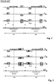
- Fig. 2 a schematic pulse sequence diagram of conventional dual-acquisition gradient-echo imaging is depicted.
- the diagram shows switched magnetic field gradients in the frequency-encoding (readout) direction M, the phase-encoding direction P, and the slice-selection direction S.
- the diagram shows RF pulses, applied in fixed time intervals of duration TR, and acquisition windows, designated by ACQ1 and ACQ2, during which gradient-echo signals are collected.
- the diagram covers the acquisition of the first two echo signals.
- the phase-encoding magnetic field gradients in the directions P and S are scaled to sample a pre-defined region of k-space. As illustrated in Fig.
- a dual-acquisition Dixon gradient-echo imaging sequence generates two echoes at two different echo times TE1 and TE2 after two RF pulses by shifting the readout magnetic field gradient within the fixed TR while keeping the phase-encoding magnetic field gradients unchanged. Due to the shifting of the readout magnetic field gradient, different phase offsets of the contributions from water and fat to the overall signal are obtained, on the basis of which the Dixon-type water/fat separation is performed. As can further be seen in Fig. 2 , the dephasing lobes of the readout magnetic field gradient in direction M and of the phase-encoding magnetic field gradients in directions P and S are shifted with the re-phasing lobe of the readout magnetic field gradient in the second depicted time interval (second acquisition).
- a method of MR imaging of an object placed in an examination volume of an MR device comprises the steps of:
- a dual- or multi-acquisition imaging sequence is used to acquire two or more sets of echo signals in separate acquisitions.
- the two or more acquisitions use separate RF excitations.
- the time interval within the meaning of the invention is the interval between successive RF refocusing pulses.
- the timing and strength of the readout magnetic field gradient are chosen to shift the acquisition windows of the two echo signals such that appropriate phase offsets of the contributions from water and fat to the overall signal are obtained, on the basis of which the Dixon-type separation of these contributions is performed in the reconstruction step.
- the essential feature of the invention is exploiting the effect that shifting and/or stretching of particular magnetic field gradient lobes in the Dixon multi-acquisition sequence has on the acoustic noise.
- the invention proposes that some of the magnetic field gradients preceding and/or succeeding the readout magnetic field gradient in each time interval are temporally shifted, varied in duration and/or varied in amplitude between time intervals (e.g. from one time interval to the next) in a targeted fashion so that acoustic noise caused by the switching of the magnetic field gradients is reduced vis-à-vis the conventional approach.
- the magnetic resonance imaging system is configured to arrange for reconstruction of the set of magnetic resonance images from the echo signals in that reconstruction software is installed in the magnetic resonance examination system's computational system or in that the computational system has access to a remote reconstruction facility.
- the reconstruction software may be installed on a remote server, e.g. in the healthcare institution of even accessible to a data-network in that the reconstruction software may be available in 'the cloud', In these remote configurations the computational system is equipped with functionality to arrange for reconstruction of the set of magnetic resonance images at the remotely located reconstruction function.
- reconstruction of the magnetic resonance image may be done by way of machine learning, for example by a trained neural network that may be incorporated ion the computational system or may be accessible from a remote location.
- a systematic approach is taken to reduce the acoustic noise on the basis of the modelling of an acoustic spectrum, involving an MR device-specific acoustic transfer function relating the frequency components of the temporal course of the switched magnetic field gradients to acoustic frequency components.
- an MR device-specific acoustic transfer function relating the frequency components of the temporal course of the switched magnetic field gradients to acoustic frequency components.
- the sequence of echo signals associated with the first and second acquisition is chosen in such a fashion that acoustic noise caused by the switching of the magnetic field gradients is minimized.
- the order in which the echo signals associated with the two or more acquisitions are collected is optimized to reduce the noise level for the patient.
- Options include an alternation between the two acquisitions after each time interval or transitions between the two acquisitions after several time intervals, as well as a single switchover from one acquisition to the other after the completion of one of the acquisitions.
- phase errors can be corrected for and do not need to be pre-emptively avoided, e.g., by always arranging the respective dephasing lobes immediately before the re-phasing lobe of the readout magnetic field gradient.
- Techniques for determining and compensating for phase errors caused by magnetic field gradient switching-induced eddy currents in Dixon imaging are known as such in the art. For example, such phase errors can be estimated in a separate calibration measurement and can be compensated either in the acquisition or the reconstruction.
- the imaging sequence applied according to the invention is a turbo spin echo (TSE) sequence comprising an RF excitation pulse succeeded by a number of RF refocusing pulses, with each of the echo signals being generated in the time interval between successive RF refocusing pulses.
- TSE turbo spin echo
- the method of the invention described thus far can be carried out by means of an MR device including at least one main magnet coil for generating an essentially uniform, static magnetic field B 0 within an examination volume, a number of gradient coils for generating switched magnetic field gradients in different spatial directions within the examination volume, at least one body RF coil for generating RF pulses within the examination volume and/or for receiving MR signals from a body of a patient positioned in the examination volume, a control unit for controlling the temporal succession of RF pulses and switched magnetic field gradients, and a reconstruction unit for reconstructing MR images from the received MR signals.
- the method of the invention can be implemented by a corresponding programming of the reconstruction unit and/or the control unit of the MR device.
- the method of the invention can be advantageously carried out on most MR devices in clinical use at present. To this end it is merely necessary to utilize a computer program by which the MR device is controlled such that it performs the above-explained method steps of the invention.
- the computer program may be present either on a data carrier or be present in a data network so as to be downloaded for installation in the control unit of the MR device.
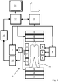
- an MR device 1 is shown as a block diagram.
- the device comprises superconducting or resistive main magnet coils 2 such that a substantially uniform, temporally constant main magnetic field B 0 is created along a z-axis through an examination volume.
- the device further comprises a set of (1 st , 2 nd , and - where applicable - 3 rd order) shimming coils 2', wherein the current flow through the individual shimming coils of the set 2' is controllable for the purpose of minimizing B 0 deviations within the examination volume.
- a magnetic resonance generation and manipulation system applies a series of RF pulses and switched magnetic field gradients to invert, excite, saturate, refocus, and spatially and otherwise encode the magnetic resonance to perform MR imaging.
- a gradient pulse amplifier 3 applies current pulses to selected ones of whole-body gradient coils 4, 5 and 6 along x, y and z-axes of the examination volume.
- a digital RF frequency transmitter 7 transmits RF pulses or pulse packets, via a send/receive switch 8, to a body RF coil 9 to transmit RF pulses into the examination volume.
- a typical MR imaging sequence is composed of a packet of RF pulse segments of short duration which, together with any applied magnetic field gradients, achieve a selected manipulation of nuclear magnetic resonance.
- the RF pulses select a portion of a body 10 positioned in the examination volume.
- the MR signals are also picked up by the body RF coil 9.
- a set of local array RF coils 11, 12, 13 are placed contiguous to the region selected for imaging.
- the array coils 11, 12, 13 can be used to receive MR signals induced by transmissions of the body RF coil.
- the resultant MR signals are picked up by the body RF coil 9 and/or by the array RF coils 11, 12, 13 and demodulated by a receiver 14 preferably including a preamplifier (not shown).
- the receiver 14 is connected to the RF coils 9, 11, 12 and 13 via the send/receive switch 8.
- a host computer 15 controls the shimming coils 2' as well as the gradient pulse amplifier 3 and the transmitter 7 to generate the imaging sequence of the invention.
- the receiver 14 receives signal data from a single or a plurality of k-space lines in rapid succession following each RF excitation pulse.
- a data acquisition system 16 performs analog-to-digital conversion of the received signals and converts each k-space line to a digital format suitable for further processing. In modern MR devices the data acquisition system 16 is a separate computer which is specialized in acquisition of raw image data.
- the digital raw image data are reconstructed into an image representation by a reconstruction processor 17 which applies a Fourier transform or other appropriate reconstruction algorithms, such as SENSE.
- the MR image may represent a planar slice through the patient, an array of parallel planar slices, a three-dimensional volume, or the like.
- the image is then stored in an image memory where it may be accessed for converting slices, projections, or other portions of the image representation into appropriate format for visualization, for example via a video monitor 18 which provides a man-readable display of the resultant MR image.
- the host computer 15 and the reconstruction processor 17 are arranged, by corresponding programming, to perform the method of the invention described herein above and in the following.
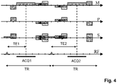
- Fig. 3 shows a pulse sequence diagram of a dual-acquisition gradient-echo sequence constituting an imaging sequence according to the invention.
- the diagram shows switched magnetic field gradients in the frequency-encoding (readout) direction M, the phase-encoding direction P, and the slice-selection direction S.
- the diagram shows the RF pulses, applied in fixed time intervals of duration TR, and acquisition windows, designated by ACQ1 and ACQ2, during which gradient-echo signals are collected in the presence of a readout magnetic field gradient in direction M.
- One gradient echo is generated in each time interval between successive RF excitations.
- the diagram covers the acquisition of the first two echo signals.
- the phase-encoding magnetic field gradients in the directions P and S are scaled to sample a pre-defined region of k-space.
- the two echoes are generated at two different echo times TE1 and TE2 after two RF pulses by shifting the readout magnetic field gradient within the fixed TR while keeping the phase-encoding magnetic field gradients unchanged. Due to the shifting of the readout magnetic field gradient and the resulting different echo times TE1 and TE2, different phase offsets of the contributions from water and fat to the overall signal are obtained, on the basis of which the Dixon-type water/fat separation is performed.
- some of the magnetic field gradients (dephasing and re-phasing lobes of phase-encoding magnetic field gradients, as well as spoiling lobes of magnetic field gradients in the example) preceding and/or succeeding the rephasing lobe of the readout magnetic field gradient are temporally shifted in relation to the pulse sequence diagram of Fig. 2 , as indicated by the arrows in Fig. 3 .
- the re-phasing lobes of the phase-encoding magnetic field gradients and the spoiling lobes of magnetic field gradients after the first acquisition are moved closer to the rephasing lobe of the readout magnetic field gradient of the first acquisition, and the dephasing lobes of the readout and phase-encoding magnetic field gradients of the second acquisition are moved farther away from the rephasing lobe of the readout magnetic field gradient of the second acquisition.
- the light grey rectangles in Fig. 3 illustrate the respective original temporal positions of the respective magnetic field gradients (corresponding to the situation shown Fig. 2 ).
- the corresponding magnetic field gradients preceding and/or succeeding the rephasing lobe of the readout magnetic field gradient are temporally stretched and, simultaneously, reduced in amplitude in relation to the pulse sequence diagram of Fig. 2 , as indicated by the arrows in Fig. 4 .
- the light grey rectangles in Fig. 4 again illustrate the respective original temporal shapes and positions of the respective magnetic field gradients.
- the invention applies the depicted shifting and/or stretching of particular lobes of the magnetic field gradients in a targeted fashion to reduce the acoustic noise generated by the multi-acquisition Dixon sequence.
- G describes the strength (amplitude) and direction of the gradient lobe
- t r denotes the relative position of the center of the plateau of the trapezoid within the time interval TR
- t p is the relative length of the plateau
- t sl and t st are the relative lengths of the leading and trailing slopes.
- the acoustic noise is then calculated, e.g., according to 10 log ⁇ n A ⁇ n H ⁇ m s ⁇ m , n 2 / a 0 , where A denotes an MR device-specific acoustic transfer function, which relates the frequency components of the temporal course of the magnetic field gradients to the corresponding frequency components of the acoustic noise, and a 0 is a suitable reference value.
- the parameters G, t r , t p , t sl and t st of each gradient lobe of the imaging sequence are adapted according to the invention in such a fashion that the acoustic noise calculated on this basis is reduced vis-à-vis the acoustic noise generated by the conventional sequence design Fig. 2 .
Landscapes
- Physics & Mathematics (AREA)
- Condensed Matter Physics & Semiconductors (AREA)
- General Physics & Mathematics (AREA)
- High Energy & Nuclear Physics (AREA)
- Engineering & Computer Science (AREA)
- Signal Processing (AREA)
- General Health & Medical Sciences (AREA)
- Health & Medical Sciences (AREA)
- Nuclear Medicine, Radiotherapy & Molecular Imaging (AREA)
- Radiology & Medical Imaging (AREA)
- Computer Vision & Pattern Recognition (AREA)
- Artificial Intelligence (AREA)
- Magnetic Resonance Imaging Apparatus (AREA)
Priority Applications (6)
| Application Number | Priority Date | Filing Date | Title |
|---|---|---|---|
| EP21156561.9A EP4043902A1 (de) | 2021-02-11 | 2021-02-11 | Mrt-bildgebung mit wasser/fett-trennung nach dixon-verfahren |
| EP22704375.9A EP4291913A1 (de) | 2021-02-11 | 2022-02-08 | Mr-bildgebung mit wasser/fett-trennung nach dixon-verfahren |
| CN202280014568.1A CN116940856A (zh) | 2021-02-11 | 2022-02-08 | 狄克逊型水/脂肪分离mr成像 |
| PCT/EP2022/052981 WO2022171608A1 (en) | 2021-02-11 | 2022-02-08 | Dixon-type water/fat separation mr imaging |
| JP2023547264A JP2024506575A (ja) | 2021-02-11 | 2022-02-08 | Dixonタイプ水/脂肪分離MR画像 |
| US18/275,816 US12360188B2 (en) | 2021-02-11 | 2022-02-08 | Dixon-type water/fat separation MR imaging |
Applications Claiming Priority (1)
| Application Number | Priority Date | Filing Date | Title |
|---|---|---|---|
| EP21156561.9A EP4043902A1 (de) | 2021-02-11 | 2021-02-11 | Mrt-bildgebung mit wasser/fett-trennung nach dixon-verfahren |
Publications (1)
| Publication Number | Publication Date |
|---|---|
| EP4043902A1 true EP4043902A1 (de) | 2022-08-17 |
Family
ID=74591856
Family Applications (2)
| Application Number | Title | Priority Date | Filing Date |
|---|---|---|---|
| EP21156561.9A Withdrawn EP4043902A1 (de) | 2021-02-11 | 2021-02-11 | Mrt-bildgebung mit wasser/fett-trennung nach dixon-verfahren |
| EP22704375.9A Pending EP4291913A1 (de) | 2021-02-11 | 2022-02-08 | Mr-bildgebung mit wasser/fett-trennung nach dixon-verfahren |
Family Applications After (1)
| Application Number | Title | Priority Date | Filing Date |
|---|---|---|---|
| EP22704375.9A Pending EP4291913A1 (de) | 2021-02-11 | 2022-02-08 | Mr-bildgebung mit wasser/fett-trennung nach dixon-verfahren |
Country Status (5)
| Country | Link |
|---|---|
| US (1) | US12360188B2 (de) |
| EP (2) | EP4043902A1 (de) |
| JP (1) | JP2024506575A (de) |
| CN (1) | CN116940856A (de) |
| WO (1) | WO2022171608A1 (de) |
Families Citing this family (3)
| Publication number | Priority date | Publication date | Assignee | Title |
|---|---|---|---|---|
| US12287385B2 (en) * | 2022-04-22 | 2025-04-29 | GE Precision Healthcare LLC | Systems and methods of noise reduction in magnetic resonance images |
| CN116823706A (zh) * | 2023-02-03 | 2023-09-29 | 上海科技大学 | 用于磁共振成像的水脂分离方法、系统及终端 |
| CN116299107A (zh) * | 2023-03-30 | 2023-06-23 | 厦门大学 | 基于重叠回波的磁共振快速水脂分离定量成像方法及系统 |
Citations (2)
| Publication number | Priority date | Publication date | Assignee | Title |
|---|---|---|---|---|
| US20120112743A1 (en) * | 2010-11-10 | 2012-05-10 | Granlund Kristin L | T2-weighted and diffusion-weighted imaging using fast acquisition with double echo (FADE) |
| WO2017207700A1 (en) * | 2016-06-02 | 2017-12-07 | Koninklijke Philips N.V. | Dixon-type water/fat separation mr imaging |
Family Cites Families (15)
| Publication number | Priority date | Publication date | Assignee | Title |
|---|---|---|---|---|
| US7112965B2 (en) * | 2004-04-30 | 2006-09-26 | University Of Basel | Low-impact noise acquisition magnetic resonance imaging |
| US8030920B2 (en) * | 2009-06-03 | 2011-10-04 | General Electric Company | Method and system for modifying pulse sequences |
| DE102013202559B3 (de) | 2013-02-18 | 2014-08-21 | Siemens Aktiengesellschaft | Optimierung einer MR-Pulssequenz durch automatisches Optimieren von Gradientenpulsen in veränderbaren Intervallen |
| US10132889B2 (en) | 2013-05-22 | 2018-11-20 | General Electric Company | System and method for reducing acoustic noise level in MR imaging |
| DE102013218475B4 (de) | 2013-09-16 | 2015-10-22 | Siemens Aktiengesellschaft | Geräuschsoptimierung einer Magnetresonanz-Sequenz durch Anhebung einer Pulsbandweite |
| DE102014202649B4 (de) | 2014-02-13 | 2015-12-10 | Siemens Aktiengesellschaft | Leise MR-Bildgebung durch eine variable Anzahl von Pulssequenzabschnitten zwischen zwei Vorpulsen |
| US9945919B2 (en) | 2014-10-09 | 2018-04-17 | Siemens Healthcare Gmbh | Systems and methods for real time gradient timing modification |
| CN107923958B (zh) * | 2015-06-26 | 2020-06-23 | 皇家飞利浦有限公司 | 相位校正的狄克逊磁共振成像 |
| JP6431464B2 (ja) * | 2015-10-07 | 2018-11-28 | 株式会社日立製作所 | 磁気共鳴イメージング装置の傾斜磁場波形調整方法、および、磁気共鳴イメージング装置 |
| JP2017140182A (ja) * | 2016-02-09 | 2017-08-17 | 株式会社日立製作所 | 磁気共鳴イメージング装置、方法及び検査プロトコル実装プログラム |
| US10175317B2 (en) * | 2016-06-10 | 2019-01-08 | Toshiba Medical Systems Corporation | Quiet MRI using alternating gradient sequence |
| US10429463B2 (en) * | 2016-06-13 | 2019-10-01 | Toshiba Medical Systems Corporation | Quiet MRI with spin echo (SE) or fast spin echo (FSE) |
| EP3511725A1 (de) * | 2018-01-11 | 2019-07-17 | Koninklijke Philips N.V. | Dixon-magnetresonanzbildgebung mit dualer auflösung |
| US11353527B2 (en) * | 2019-07-19 | 2022-06-07 | Shanghai United Imaging Healthcare Co., Ltd. | Systems and methods for waveform determination in magnetic resonance imaging |
| WO2021026143A1 (en) * | 2019-08-06 | 2021-02-11 | Hi Llc | Systems and methods having an optical magnetometer array with beam splitters |
-
2021
- 2021-02-11 EP EP21156561.9A patent/EP4043902A1/de not_active Withdrawn
-
2022
- 2022-02-08 WO PCT/EP2022/052981 patent/WO2022171608A1/en not_active Ceased
- 2022-02-08 CN CN202280014568.1A patent/CN116940856A/zh active Pending
- 2022-02-08 EP EP22704375.9A patent/EP4291913A1/de active Pending
- 2022-02-08 JP JP2023547264A patent/JP2024506575A/ja active Pending
- 2022-02-08 US US18/275,816 patent/US12360188B2/en active Active
Patent Citations (2)
| Publication number | Priority date | Publication date | Assignee | Title |
|---|---|---|---|---|
| US20120112743A1 (en) * | 2010-11-10 | 2012-05-10 | Granlund Kristin L | T2-weighted and diffusion-weighted imaging using fast acquisition with double echo (FADE) |
| WO2017207700A1 (en) * | 2016-06-02 | 2017-12-07 | Koninklijke Philips N.V. | Dixon-type water/fat separation mr imaging |
Non-Patent Citations (3)
| Title |
|---|
| D. HERNANDO ET AL: "Addressing phase errors in fat-water imaging using a mixed magnitude/complex fitting method", MAGNETIC RESONANCE IN MEDICINE, vol. 67, no. 3, 1 March 2012 (2012-03-01), pages 638 - 644, XP055027305, ISSN: 0740-3194, DOI: 10.1002/mrm.23044 * |
| EGGERS ET AL., JOURNAL OF MAGNETIC RESONANCE IMAGING, vol. 40, 2014, pages 251 - 268 |
| EGGERS ET AL., MAGNETIC RESONANCE IN MEDICINE, vol. 65, 2011, pages 96 - 107 |
Also Published As
| Publication number | Publication date |
|---|---|
| CN116940856A (zh) | 2023-10-24 |
| US12360188B2 (en) | 2025-07-15 |
| US20240094320A1 (en) | 2024-03-21 |
| JP2024506575A (ja) | 2024-02-14 |
| WO2022171608A1 (en) | 2022-08-18 |
| EP4291913A1 (de) | 2023-12-20 |
Similar Documents
| Publication | Publication Date | Title |
|---|---|---|
| US9223001B2 (en) | MR imaging using navigators | |
| EP2992351A1 (de) | Dixon-wasser/fetttrennungs-mrt mit hohem snr in einem phasenbild und niedrigem snr in einem mindestens teilweise phasenversetzten bild | |
| EP3673281B1 (de) | Wasser-fett-trennung nach dixon-verfahren mit mr-tomografie | |
| US12360188B2 (en) | Dixon-type water/fat separation MR imaging | |
| WO2015092619A1 (en) | Phase-sensitive inversion recovery mri with water/fat separation | |
| US20220057467A1 (en) | Epi mr imaging with distortion correction | |
| US11543482B2 (en) | Magnetic resonance imaging using motion-compensated image reconstruction | |
| US20190310336A1 (en) | Mr imaging with dixon-type water/fat separation | |
| WO2018114554A1 (en) | Dixon-type water/fat separation mr imaging | |
| EP3185029A1 (de) | Mr-bildgebung mit propellererfassung mit t2-zerfallskorrektur | |
| US12392851B2 (en) | Dixon-type water/fat separation MR imaging | |
| EP4097498B1 (de) | Mrt-bildgebung unter verwendung einer wasser/fett-trennung nach dixon mit unterdrückung von strömungsinduzierter leckage und/oder vertauschungs-artefakten | |
| US11226385B2 (en) | Dixon type water/fat separation MR imaging with improved fat shift correction | |
| US12140653B2 (en) | Dixon-type water/fat separation MR imaging | |
| EP3118643A1 (de) | Dynamische propeller-mr-bildgebung |
Legal Events
| Date | Code | Title | Description |
|---|---|---|---|
| PUAI | Public reference made under article 153(3) epc to a published international application that has entered the european phase |
Free format text: ORIGINAL CODE: 0009012 |
|
| STAA | Information on the status of an ep patent application or granted ep patent |
Free format text: STATUS: THE APPLICATION HAS BEEN PUBLISHED |
|
| AK | Designated contracting states |
Kind code of ref document: A1 Designated state(s): AL AT BE BG CH CY CZ DE DK EE ES FI FR GB GR HR HU IE IS IT LI LT LU LV MC MK MT NL NO PL PT RO RS SE SI SK SM TR |
|
| STAA | Information on the status of an ep patent application or granted ep patent |
Free format text: STATUS: THE APPLICATION IS DEEMED TO BE WITHDRAWN |
|
| 18D | Application deemed to be withdrawn |
Effective date: 20230218 |