EP4097498B1 - Mrt-bildgebung unter verwendung einer wasser/fett-trennung nach dixon mit unterdrückung von strömungsinduzierter leckage und/oder vertauschungs-artefakten - Google Patents
Mrt-bildgebung unter verwendung einer wasser/fett-trennung nach dixon mit unterdrückung von strömungsinduzierter leckage und/oder vertauschungs-artefakten Download PDFInfo
- Publication number
- EP4097498B1 EP4097498B1 EP21701323.4A EP21701323A EP4097498B1 EP 4097498 B1 EP4097498 B1 EP 4097498B1 EP 21701323 A EP21701323 A EP 21701323A EP 4097498 B1 EP4097498 B1 EP 4097498B1
- Authority
- EP
- European Patent Office
- Prior art keywords
- phase
- echo
- flow
- different
- cardiac
- Prior art date
- Legal status (The legal status is an assumption and is not a legal conclusion. Google has not performed a legal analysis and makes no representation as to the accuracy of the status listed.)
- Active
Links
Images

Classifications
-
- G—PHYSICS
- G01—MEASURING; TESTING
- G01R—MEASURING ELECTRIC VARIABLES; MEASURING MAGNETIC VARIABLES
- G01R33/00—Arrangements or instruments for measuring magnetic variables
- G01R33/20—Arrangements or instruments for measuring magnetic variables involving magnetic resonance
- G01R33/44—Arrangements or instruments for measuring magnetic variables involving magnetic resonance using nuclear magnetic resonance [NMR]
- G01R33/48—NMR imaging systems
- G01R33/4828—Resolving the MR signals of different chemical species, e.g. water-fat imaging
-
- G—PHYSICS
- G01—MEASURING; TESTING
- G01R—MEASURING ELECTRIC VARIABLES; MEASURING MAGNETIC VARIABLES
- G01R33/00—Arrangements or instruments for measuring magnetic variables
- G01R33/20—Arrangements or instruments for measuring magnetic variables involving magnetic resonance
- G01R33/44—Arrangements or instruments for measuring magnetic variables involving magnetic resonance using nuclear magnetic resonance [NMR]
- G01R33/48—NMR imaging systems
- G01R33/54—Signal processing systems, e.g. using pulse sequences ; Generation or control of pulse sequences; Operator console
- G01R33/56—Image enhancement or correction, e.g. subtraction or averaging techniques, e.g. improvement of signal-to-noise ratio and resolution
- G01R33/561—Image enhancement or correction, e.g. subtraction or averaging techniques, e.g. improvement of signal-to-noise ratio and resolution by reduction of the scanning time, i.e. fast acquiring systems, e.g. using echo-planar pulse sequences
- G01R33/5615—Echo train techniques involving acquiring plural, differently encoded, echo signals after one RF excitation, e.g. using gradient refocusing in echo planar imaging [EPI], RF refocusing in rapid acquisition with relaxation enhancement [RARE] or using both RF and gradient refocusing in gradient and spin echo imaging [GRASE]
-
- G—PHYSICS
- G01—MEASURING; TESTING
- G01R—MEASURING ELECTRIC VARIABLES; MEASURING MAGNETIC VARIABLES
- G01R33/00—Arrangements or instruments for measuring magnetic variables
- G01R33/20—Arrangements or instruments for measuring magnetic variables involving magnetic resonance
- G01R33/44—Arrangements or instruments for measuring magnetic variables involving magnetic resonance using nuclear magnetic resonance [NMR]
- G01R33/48—NMR imaging systems
- G01R33/54—Signal processing systems, e.g. using pulse sequences ; Generation or control of pulse sequences; Operator console
- G01R33/56—Image enhancement or correction, e.g. subtraction or averaging techniques, e.g. improvement of signal-to-noise ratio and resolution
- G01R33/563—Image enhancement or correction, e.g. subtraction or averaging techniques, e.g. improvement of signal-to-noise ratio and resolution of moving material, e.g. flow contrast angiography
- G01R33/56308—Characterization of motion or flow; Dynamic imaging
- G01R33/56316—Characterization of motion or flow; Dynamic imaging involving phase contrast techniques
-
- G—PHYSICS
- G01—MEASURING; TESTING
- G01R—MEASURING ELECTRIC VARIABLES; MEASURING MAGNETIC VARIABLES
- G01R33/00—Arrangements or instruments for measuring magnetic variables
- G01R33/20—Arrangements or instruments for measuring magnetic variables involving magnetic resonance
- G01R33/44—Arrangements or instruments for measuring magnetic variables involving magnetic resonance using nuclear magnetic resonance [NMR]
- G01R33/48—NMR imaging systems
- G01R33/54—Signal processing systems, e.g. using pulse sequences ; Generation or control of pulse sequences; Operator console
- G01R33/56—Image enhancement or correction, e.g. subtraction or averaging techniques, e.g. improvement of signal-to-noise ratio and resolution
- G01R33/565—Correction of image distortions, e.g. due to magnetic field inhomogeneities
- G01R33/56509—Correction of image distortions, e.g. due to magnetic field inhomogeneities due to motion, displacement or flow, e.g. gradient moment nulling
-
- G—PHYSICS
- G01—MEASURING; TESTING
- G01R—MEASURING ELECTRIC VARIABLES; MEASURING MAGNETIC VARIABLES
- G01R33/00—Arrangements or instruments for measuring magnetic variables
- G01R33/20—Arrangements or instruments for measuring magnetic variables involving magnetic resonance
- G01R33/44—Arrangements or instruments for measuring magnetic variables involving magnetic resonance using nuclear magnetic resonance [NMR]
- G01R33/48—NMR imaging systems
- G01R33/54—Signal processing systems, e.g. using pulse sequences ; Generation or control of pulse sequences; Operator console
- G01R33/56—Image enhancement or correction, e.g. subtraction or averaging techniques, e.g. improvement of signal-to-noise ratio and resolution
- G01R33/5608—Data processing and visualization specially adapted for MR, e.g. for feature analysis and pattern recognition on the basis of measured MR data, segmentation of measured MR data, edge contour detection on the basis of measured MR data, for enhancing measured MR data in terms of signal-to-noise ratio by means of noise filtering or apodization, for enhancing measured MR data in terms of resolution by means for deblurring, windowing, zero filling, or generation of gray-scaled images, colour-coded images or images displaying vectors instead of pixels
-
- G—PHYSICS
- G01—MEASURING; TESTING
- G01R—MEASURING ELECTRIC VARIABLES; MEASURING MAGNETIC VARIABLES
- G01R33/00—Arrangements or instruments for measuring magnetic variables
- G01R33/20—Arrangements or instruments for measuring magnetic variables involving magnetic resonance
- G01R33/44—Arrangements or instruments for measuring magnetic variables involving magnetic resonance using nuclear magnetic resonance [NMR]
- G01R33/48—NMR imaging systems
- G01R33/54—Signal processing systems, e.g. using pulse sequences ; Generation or control of pulse sequences; Operator console
- G01R33/56—Image enhancement or correction, e.g. subtraction or averaging techniques, e.g. improvement of signal-to-noise ratio and resolution
- G01R33/561—Image enhancement or correction, e.g. subtraction or averaging techniques, e.g. improvement of signal-to-noise ratio and resolution by reduction of the scanning time, i.e. fast acquiring systems, e.g. using echo-planar pulse sequences
- G01R33/5615—Echo train techniques involving acquiring plural, differently encoded, echo signals after one RF excitation, e.g. using gradient refocusing in echo planar imaging [EPI], RF refocusing in rapid acquisition with relaxation enhancement [RARE] or using both RF and gradient refocusing in gradient and spin echo imaging [GRASE]
- G01R33/5616—Echo train techniques involving acquiring plural, differently encoded, echo signals after one RF excitation, e.g. using gradient refocusing in echo planar imaging [EPI], RF refocusing in rapid acquisition with relaxation enhancement [RARE] or using both RF and gradient refocusing in gradient and spin echo imaging [GRASE] using gradient refocusing, e.g. EPI
-
- G—PHYSICS
- G01—MEASURING; TESTING
- G01R—MEASURING ELECTRIC VARIABLES; MEASURING MAGNETIC VARIABLES
- G01R33/00—Arrangements or instruments for measuring magnetic variables
- G01R33/20—Arrangements or instruments for measuring magnetic variables involving magnetic resonance
- G01R33/44—Arrangements or instruments for measuring magnetic variables involving magnetic resonance using nuclear magnetic resonance [NMR]
- G01R33/48—NMR imaging systems
- G01R33/54—Signal processing systems, e.g. using pulse sequences ; Generation or control of pulse sequences; Operator console
- G01R33/56—Image enhancement or correction, e.g. subtraction or averaging techniques, e.g. improvement of signal-to-noise ratio and resolution
- G01R33/567—Image enhancement or correction, e.g. subtraction or averaging techniques, e.g. improvement of signal-to-noise ratio and resolution gated by physiological signals, i.e. synchronization of acquired MR data with periodical motion of an object of interest, e.g. monitoring or triggering system for cardiac or respiratory gating
- G01R33/5673—Gating or triggering based on a physiological signal other than an MR signal, e.g. ECG gating or motion monitoring using optical systems for monitoring the motion of a fiducial marker
Definitions
- the invention relates to the field of magnetic resonance (MR) imaging. It concerns a method of MR imaging of an object placed in the examination volume of a MR device.
- the invention also relates to a MR device and to a computer program to be run on a MR device.
- Image-forming MR methods which utilize the interaction between magnetic fields and nuclear spins in order to form two-dimensional or three-dimensional images are widely used nowadays, notably in the field of medical diagnostics, because for the imaging of soft tissue they are superior to other imaging methods in many respects, do not require ionizing radiation and are usually not invasive.
- the body of the patient to be examined is arranged in a strong, uniform magnetic field B 0 whose direction at the same time defines an axis (normally the z-axis) of the co-ordinate system on which the measurement is based.
- the magnetic field B 0 produces different energy levels for the individual nuclear spins in dependence on the magnetic field strength which can be excited (spin resonance) by application of an electromagnetic alternating field (RF field) of defined frequency (so-called Larmor frequency, or MR frequency).
- the distribution of the individual nuclear spins produces an overall magnetization which can be deflected out of the state of equilibrium by application of an electromagnetic pulse of appropriate frequency (RF pulse) perpendicular to the z-axis, so that the magnetization performs a precessional motion about the z-axis.
- the precessional motion describes a surface of a cone whose angle of aperture is referred to as flip angle.
- the magnitude of the flip angle is dependent on the strength and the duration of the applied electromagnetic pulse.
- 90° pulse the spins are deflected from the z-axis to the transverse plane (flip angle 90°).
- the magnetization relaxes back to the original state of equilibrium, in which the magnetization in the z direction is built up again with a first time constant T 1 (spin-lattice or longitudinal relaxation time), and the magnetization in the direction perpendicular to the z direction relaxes with a second time constant T 2 (spin-spin or transverse relaxation time).
- T 1 spin-lattice or longitudinal relaxation time
- T 2 spin-spin or transverse relaxation time
- the decay of the transverse magnetization is accompanied, after application of, for example, a 90° pulse, by a transition of the nuclear spins (induced by local magnetic field inhomogeneities) from an ordered state with the same phase to a state in which all phase angles are uniformly distributed (dephasing).
- the dephasing can be compensated by means of a refocusing pulse (for example a 180° pulse). This produces an echo signal in the receiving coils.
- the signal picked up in the receiving coils then contains components of different frequencies which can be associated with different locations in the body.
- the signal data obtained via the receiving coils correspond to the spatial frequency domain and are called k-space data.
- the k-space data usually include multiple lines acquired with different phase encoding. Each k-space line is digitized by collecting a number of samples. A set of k-space data is converted to an MR image, e.g., by means of Fourier transformation.
- Various strategies can be used in Dixon imaging for acquiring echo signals at two different echo times, including: (i) dual-pass strategies, wherein each echo signal is acquired separately after an excitation RF pulse using a positive amplitude readout magnetic field gradient, (ii) fly-back strategies, wherein both echo signals are acquired after the same excitation RF pulse using a positive amplitude readout magnetic field gradient in combination with a negative amplitude re-winder magnetic field gradient, and (iii) bipolar strategies, wherein both echo signals are acquired after the same excitation RF pulse, one echo being acquired using a positive amplitude readout magnetic field gradient and the other echo being acquired using a negative amplitude readout magnetic field gradient.
- Bipolar strategies permit reaching a high sampling efficiency, but they suffer from several phase errors.
- bipolar gradients are known to be flow sensitizing because they lead to a phase offset in the MR signal of moving spins proportional to their velocity in the direction of the readout magnetic field gradient.
- flow-induced phase offsets can be a source for undesired misallocations of MR signal to fat and water images (see Rahimi et al., Magn. Reson. Med., 73:1926-1931, 2015 ).
- Such artifacts are of particular concern in the MR imaging-based evaluation of blood vessels (MR angiography), since they may falsely suggest the presence of an intravascular clot or a higher severity of a stenosis.
- US 10,175,330 B2 discloses a method of MR imaging that enables efficient compensation of flow artifacts for MR angiography in combination with Dixon water/fat separation.
- MR echo signals are acquired at two or more different echo times using a conventional Dixon technique, and single-echo MR images are reconstructed from the acquired MR echo signals, one for each of the two or more echo times.
- Blood vessels are extracted from the single-echo MR images using image segmentation to suppress artifacts in the water/fat separation arising from the application of Dixon methods in the presence of flow.
- a method of MR imaging of a body of a patient placed in an examination volume of a MR device is provided in accordance with independent claim 1.
- the method comprises the following steps:
- dual-echo Dixon MR imaging is performed. Pairs of echo signals are acquired, wherein the first echo signal of each pair is associated with a first echo time while the second echo signal of each pair is associated with a second echo time that is different from the first echo time. A number of such pairs is acquired with different phase encodings to sample a given k-space region according to the respective imaging task. This means that both echo signals of each pair share the same phase encoding and each pair of echo signals is assigned one specific phase encoding.
- the essential feature of the invention is that the acquisition of each pair of echo signals is repeated during two or more different phases of the cardiac cycle. This means, in other words, that the k-space region is sampled at least twice, namely once for each of the two or more different cardiac phases.
- phase images associated with different echo times, together with the corresponding magnitude images are the basis for reconstructing the final diagnostic image, which may be a water image or a fat image, i.e., an MR image showing only signal contributions from water or fat, respectively, using a two-point Dixon algorithm for the water/fat separation.
- Flow-induced artifacts are suppressed therein by taking the determined regions of flow and/or the estimated phase errors into account, e.g. by appropriately removing the flow-induced phase offsets in the corresponding areas of the single-echo phase images prior to the water/fat separation.
- the result is a diagnostic (water or fat) image of high quality with a significantly reduced level of flow-induced leakage or swapping artifacts.
- the pairs of echo signals are generated after different temporal delays after detection of a cardiac trigger signal.
- Cardiac triggering may be achieved, e.g., by additional acquisition of an ECG signal.
- the different cardiac phases can be selected by choosing appropriate trigger delays. These choices may be based on prior knowledge of the temporal variation in the blood flow over the cardiac cycle, or on a suitable calibration measurement that provides quantitative information on the velocity of the blood flow in selected vessels. The latter variant may also be used to trade off the expected cardiac motion and blood flow.
- the pairs of echo signals are acquired using bipolar readout magnetic field gradients.
- the two echo signals of each pair are acquired using a corresponding pair of temporally adjoining readout magnetic field gradients having opposed polarities.
- the first echo is acquired at the first echo time using a positive amplitude readout magnetic field gradient and the second echo is acquired at the second echo time using a negative amplitude readout magnetic field gradient (or vice versa).
- the regions of flow are determined from the phase images by image processing techniques such as masking, thresholding or segmentation.
- the redundant information contained in the echo signals generated during different cardiac phases are used for noise reduction by averaging in the step of reconstructing the diagnostic image.
- a flow velocity map can be derived from the phase images to support the derivation of useful quantitative parameters, such as stroke volume.
- the invention thus proposes a suppression of flow-induced leakage and swapping artifacts in bipolar dual-echo Dixon imaging by acquisition of pairs of echo signals in different cardiac phases. Undesirable signal swaps or misallocations due to flow are significantly reduced by the method of the invention.
- the method of the invention described thus far can be carried out by means of a MR device including at least one main magnet coil for generating an essentially uniform, static magnetic field B 0 within an examination volume, a number of gradient coils for generating switched magnetic field gradients in different spatial directions within the examination volume, at least one body RF coil for generating RF pulses within the examination volume and/or for receiving MR signals from a body of a patient positioned in the examination volume, a control unit for controlling the temporal succession of RF pulses and switched magnetic field gradients, and a reconstruction unit for reconstructing MR images from the received MR signals.
- the method of the invention can be implemented by a corresponding programming of the reconstruction unit and/or the control unit of the MR device.
- the method of the invention can be advantageously carried out on most MR devices in clinical use at present. To this end it is merely necessary to utilize a computer program by which the MR device is controlled such that it performs the above-explained method steps of the invention.
- the computer program may be present either on a data carrier or be present in a data network so as to be downloaded for installation in the control unit of the MR device.
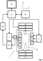
- a MR device 1 is shown as a block diagram.
- the device comprises superconducting or resistive main magnet coils 2 such that a substantially uniform, temporally constant main magnetic field B 0 is created along a z-axis through an examination volume.
- the device further comprises a set of (1 st , 2 nd , and - where applicable - 3 rd order) shimming coils 2', wherein the current flow through the individual shimming coils of the set 2' is controllable for the purpose of minimizing B 0 deviations within the examination volume.
- a magnetic resonance generation and manipulation system applies a series of RF pulses and switched magnetic field gradients to invert or excite nuclear magnetic spins, induce magnetic resonance, refocus magnetic resonance, manipulate magnetic resonance, spatially and otherwise encode magnetic resonance, saturate spins, and the like to perform MR imaging.
- a gradient pulse amplifier 3 applies current pulses to selected ones of whole-body gradient coils 4, 5 and 6 along x, y and z-axes of the examination volume.
- a digital RF frequency transmitter 7 transmits RF pulses or pulse packets, via a send/receive switch 8, to a body RF coil 9 to transmit RF pulses into the examination volume.
- a typical MR imaging sequence is composed of a packet of RF pulse segments of short duration which, together with any applied magnetic field gradients, achieve a selected manipulation of nuclear magnetic resonance.
- the RF pulses are used to saturate magnetic resonance, excite magnetic resonance, invert magnetization, refocus magnetic resonance, or manipulate magnetic resonance. In particular, they are used to select a portion of a body 10 positioned in the examination volume.
- the MR signals are also picked up by the body RF coil 9.
- a set of local array RF coils 11, 12, 13 are placed contiguous to the region selected for imaging.
- the array coils 11, 12, 13 can be used to receive MR signals induced by RF transmissions via the body RF coil.
- the resultant MR signals are picked up by the body RF coil 9 and/or by the array RF coils 11, 12, 13 and demodulated by a receiver 14 preferably including a preamplifier (not shown).
- the receiver 14 is connected to the RF coils 9, 11, 12 and 13 via the send/receive switch 8.
- a host computer 15 controls the shimming coils 2' as well as the gradient pulse amplifier 3 and the transmitter 7 to generate the imaging sequences of the invention.
- the receiver 14 receives a single or a plurality of MR data lines in rapid succession following each RF excitation pulse.
- a data acquisition system 16 performs analog-to-digital conversion of the received signals and converts each MR data line to a digital format suitable for further processing. In modern MR devices the data acquisition system 16 is a separate computer which is specialized in acquisition of raw image data.
- the digital raw image data are reconstructed into an image representation by a reconstruction processor 17 which applies a Fourier transform or other appropriate reconstruction algorithms, such as SENSE.
- the MR image may represent a planar slice through the patient, an array of parallel planar slices, a three-dimensional volume, or the like.
- the image is then stored in an image memory where it may be accessed for converting slices, projections, or other portions of the image representation into an appropriate format for visualization, for example via a video monitor 18 which provides a man-readable display of the resultant MR image.
- the host computer 15 and the reconstruction processor 17 are programmed to execute the method of the invention as described above and in the following.
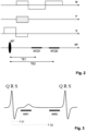
- a schematic pulse sequence diagram of a Dixon imaging sequence using bipolar readout magnetic field gradients according to the invention is depicted.
- the diagram shows switched magnetic field gradients in the frequency-encoding direction (M), the phase-encoding direction (P) and the slice-selection direction (S).
- the diagram shows an RF excitation pulse as well as the time intervals during which echo signals are acquired, designated by ACQ1 and ACQ2.
- the diagram covers the acquisition of one pair of echo signals. A number of such pairs of echo signals is acquired by multiple repetitions of the depicted sequence using different phase encodings (P) to completely cover the required region of k-space.
- Each pair of echo signals is acquired using a corresponding pair of readout magnetic field gradients (M) having opposed polarities.
- the timing and amplitudes of the bipolar readout gradients are chosen to shift the acquisition windows ACQ1, ACQ2 of the echo signals such that different echo times TE1 and TE2 and correspondingly different phase offsets of the signal contributions from water protons and fat protons are provided.
- the Dixon-type separation of these signal contributions is based on these phase offsets in the final step of the reconstruction of a diagnostic water or fat image.
- the acquisition of each pair of echo signals is repeated during two or more different phases of the cardiac cycle.
- Fig.3 Two consecutive QRS complexes of an ECG signal acquired from the body 10 of the patient are shown. Two acquisition windows AW1 and AW2 are indicated that are associated with different cardiac phases. The acquisition of a pair of echo signals is performed once for each acquisition window AW1, AW2.
- the pairs of echo signals are acquired after different temporal delays after detection of a cardiac trigger signal (e.g. the R-peak of the ECG-signal). The different cardiac phases are selected by choosing appropriate trigger delays.
- the corresponding two trigger delays D1 and D2 are indicated in Fig.3 .
- phase images are reconstructed from the acquired echo signal data.
- One phase image is reconstructed for each echo time TE1, TE2 and acquisition window AW1, AW2.
- a set of corresponding images of the thorax region is shown in Fig.4 .
- Magnitude (left) and phase (right) images for the two cardiac phases associated with the two acquisition windows AW1, AW2 (rows) and for the two echo times TE1, TE2 (columns) are provided.
- the velocity of the blood flow in the aorta is close to the maximum in the first selected cardiac phase (AW1) and close to the minimum in the second selected cardiac phase (AW2). Accordingly, flow-induced phase offsets are substantially larger at the first echo time TE1.
- Differences in the phase images for one cardiac phase AW1, AW2 reflect main magnetic field inhomogeneity, chemical shift, and flow, while differences in the phase images at one echo time TE1 or TE2 (i.e., phase images of one column in Fig.4 ) mainly arise from flow only.
- differences in the phase images at one echo time are primarily seen at the first echo time TE1, due to the so-called even-echo rephasing effect. Any significant motion between the phase images may be corrected in a conventional fashion, e.g. using registration based on the corresponding magnitude images.
- phase difference images may be calculated directly from the phase images at each echo time TE1, TE2.
- Phase difference images derived from the phase images in Fig.4 are shown in Fig.5 .
- the phase difference image associated with the first echo time TE1 allows a localization of relevant blood flow in the aorta (indicated by white arrow), for instance by masking, thresholding, segmentation, or the like.
- a diagnostic image is reconstructed involving water/fat separation.
- a suppression of leakage and swapping artifacts is achieved by either removing the flow-induced phase offsets in the determined regions prior to the water/fat separation, or by constraining the water/fat separation algorithm such that the blood signal is automatically allocated to the water signal in the determined regions of flow.
- the latter approach may involve reducing or removing any spatial smoothing of the estimated main field inhomogeneity in the water/fat separation, for instance selectively across the boundaries of these regions.
- the result of this procedure is a diagnostic (water or fat) image of high quality with a significantly reduced level of flow-induced leakage or swapping artifacts.
Landscapes
- Physics & Mathematics (AREA)
- High Energy & Nuclear Physics (AREA)
- Condensed Matter Physics & Semiconductors (AREA)
- General Physics & Mathematics (AREA)
- Health & Medical Sciences (AREA)
- Nuclear Medicine, Radiotherapy & Molecular Imaging (AREA)
- General Health & Medical Sciences (AREA)
- Radiology & Medical Imaging (AREA)
- Engineering & Computer Science (AREA)
- Signal Processing (AREA)
- Vascular Medicine (AREA)
- Magnetic Resonance Imaging Apparatus (AREA)
Claims (10)
- Verfahren zur MR-Bildgebung eines Körpers eines Patienten (10), der in einem Untersuchungsvolumen eines MR-Geräts (1) platziert ist, wobei das Verfahren folgende Schritte umfasst:- Einen Körper (10) einer Bildgebungssequenz zu unterziehen, bestehend aus mindestens einem Anregungs-RF-Impuls und geschalteten Magnetfeldgradienten, wobei eine Anzahl von Paaren von Echosignalen zu zwei verschiedenen Echozeiten (TE1, TE2) mit unterschiedlichen Phasenkodierungen erzeugt wird, um einen Bereich des k-Raums abzutasten, und wobei die Erzeugung jedes Paares von Echosignalen während zweier oder mehrerer verschiedener Herzphasen (AW1, AW2) eines Herzzyklus wiederholt wird;- Erfassen der Echosignale des Körpers (10);- Rekonstruktion von Phasenbildern aus den erfassten Echosignaldaten, wobei für jede Echozeit und jede Herzphase ein Phasenbild rekonstruiert wird; und- Rekonstruktion eines endgültigen diagnostischen Bildes aus den Echosignaldaten mittels Wasser-Fetttrennung, wobei sich die Schwankungen der Blutflussgeschwindigkeit über den Herzzyklus in lokalen Phasenverschiebungen zwischen den Phasenbildern der verschiedenen Herzphasen widerspiegeln, so dass Strömungsbereiche und/oder Schätzungen von strömungs-induzierten Phasenfehlern aus den Phasenbildern abgeleitet werden, um strömungsinduzierte Leckagen und/oder Austauschartefakte im endgültigen Diagnosebild zu unterdrücken oder auszugleichen.
- Verfahren nach Anspruch 1, wobei die Paare von Echosignalen nach verschiedenen Verzögerungen (D1, D2) nach Erkennung eines Herztriggersignals erzeugt werden.
- Verfahren nach Anspruch 1 oder 2, wobei die Paare von Echosignalen unter Verwendung von bipolaren Auslese-Magnetfeldgradienten (M) erfasst werden.
- Verfahren nach einem der Ansprüche 1-3, dadurch gekennzeichnet, dass Bereiche von Fluss und/oder flussinduzierten Phasenfehlern durch voxelweisen Vergleich von Phasenbildern bestimmt werden, die zu verschiedenen Herzphasen gehören.
- Verfahren nach Anspruch 4, wobei die Strömungsbereiche durch ein Bildverarbeitungsverfahren wie Maskierung, Schwellenwertbestimmung oder Segmentierung bestimmt werden.
- Verfahren nach einem der Ansprüche 1-5, wobei die während verschiedener Herzzyklen erzeugten Echosignale zur Bildung eines Durchschnittswerts im Schritt der Rekonstruktion des Diagnosebildes verwendet werden.
- Verfahren nach einem der Ansprüche 1-6, dadurch gekennzeichnet, dass aus den lokalen Phasenverschiebungen in den Phasenbildern eine Zuordnung der Strömungsgeschwindigkeit abgeleitet wird.
- Verfahren nach einem der Ansprüche 1-7, wobei die Wasser Fett Trennung eine zwei Punkt Dixon Technik umfasst.
- MR Vorrichtung mit mindestens einer Hauptmagnetspule (2) zur Erzeugung eines gleichmäßigen, statischen Magnetfeldes B0 innerhalb eines Untersuchungsvolumens, einer Anzahl von Gradientenspulen (4, 5, 6) zur Erzeugung von geschalteten Magnetfeldgradienten in verschiedenen räumlichen Richtungen innerhalb des Untersuchungsvolumens, mindestens eine RF Spule (9) zur Erzeugung von RF Impulsen innerhalb des Untersuchungsvolumens und/oder zum Empfang von MR Signalen von einem im Untersuchungsvolumen positionierten Körper eines Patienten (10), eine Steuereinheit (15) zur Steuerung der zeitlichen Folge von RF Impulsen und geschalteten Magnetfeldgradienten, und eine Rekonstruktionseinheit (17) zur Rekonstruktion von MR-Bildern aus den empfangenen MR Signalen, wobei das MR-Gerät (1) für die Ausführung der folgenden Schritte konfiguriert ist:- Den Körper (10) einer Bildgebungssequenz zu unterziehen, bestehend aus mindestens einem Anregungs RF Impuls und geschalteten Magnetfeldgradienten, wobei eine Anzahl von Paaren von Echosignalen zu zwei verschiedenen Echozeiten (TE1, TE2) mit unterschiedlichen Phasenkodierungen erzeugt wird, um einen Bereich des k-Raums abzutasten, und wobei die Erzeugung jedes Paares von Echosignalen während zweier oder mehrerer verschiedener Herzphasen (AW1, AW2) eines Herzzyklus wiederholt wird;- Erfassen der Echosignale des Körpers (10);- Rekonstruktion von Phasenbildern aus den erfassten Echosignaldaten, wobei für jede Echozeit und jede Herzphase ein Phasenbild rekonstruiert wird; und- Rekonstruktion eines endgültigen diagnostischen Bildes aus den Echosignaldaten mittels Wasser/Fetttrennung, wobei sich die Schwankungen der Blutflussgeschwindigkeit über den Herzzyklus in lokalen Phasenverschiebungen zwischen den Phasenbildern der verschiedenen Herzphasen widerspiegeln; so dass Strömungsbereiche und/oder Schätzungen von strömungs-induzierten Phasenfehlern aus den Phasenbildern abgeleitet werden, um strömungsinduzierte Leckagen und/oder Austauschartefakte im endgültigen Diagnosebild zu unterdrücken oder auszugleichen.
- Computerprogramm, das auf einem MR-Gerät ausgeführt werden soll, wobei das Computerprogramm Anweisungen umfasst, die, wenn sie auf dem MR Gerät ausgeführt werden, das MR Gerät veranlassen, das Verfahren nach Anspruch 1 auszuführen.
Applications Claiming Priority (2)
| Application Number | Priority Date | Filing Date | Title |
|---|---|---|---|
| EP20154518.3A EP3859366A1 (de) | 2020-01-30 | 2020-01-30 | Mrt-bildgebung unter verwendung von dixonartiger wasser/fett-trennung mit unterdrückung von strömungsinduzierter leckage und/oder überlagerung von artefakten |
| PCT/EP2021/051542 WO2021151805A1 (en) | 2020-01-30 | 2021-01-25 | Mr imaging using dixon-type water/fat separation with suppression of flow-induced leakage and/or swapping artifacts |
Publications (2)
| Publication Number | Publication Date |
|---|---|
| EP4097498A1 EP4097498A1 (de) | 2022-12-07 |
| EP4097498B1 true EP4097498B1 (de) | 2024-03-27 |
Family
ID=69411278
Family Applications (2)
| Application Number | Title | Priority Date | Filing Date |
|---|---|---|---|
| EP20154518.3A Withdrawn EP3859366A1 (de) | 2020-01-30 | 2020-01-30 | Mrt-bildgebung unter verwendung von dixonartiger wasser/fett-trennung mit unterdrückung von strömungsinduzierter leckage und/oder überlagerung von artefakten |
| EP21701323.4A Active EP4097498B1 (de) | 2020-01-30 | 2021-01-25 | Mrt-bildgebung unter verwendung einer wasser/fett-trennung nach dixon mit unterdrückung von strömungsinduzierter leckage und/oder vertauschungs-artefakten |
Family Applications Before (1)
| Application Number | Title | Priority Date | Filing Date |
|---|---|---|---|
| EP20154518.3A Withdrawn EP3859366A1 (de) | 2020-01-30 | 2020-01-30 | Mrt-bildgebung unter verwendung von dixonartiger wasser/fett-trennung mit unterdrückung von strömungsinduzierter leckage und/oder überlagerung von artefakten |
Country Status (4)
| Country | Link |
|---|---|
| US (1) | US11940517B2 (de) |
| EP (2) | EP3859366A1 (de) |
| CN (1) | CN115023622A (de) |
| WO (1) | WO2021151805A1 (de) |
Families Citing this family (1)
| Publication number | Priority date | Publication date | Assignee | Title |
|---|---|---|---|---|
| CN117148244A (zh) * | 2022-05-24 | 2023-12-01 | 上海联影医疗科技股份有限公司 | 图像水脂分离方法、装置、设备和计算机可读存储介质 |
Family Cites Families (6)
| Publication number | Priority date | Publication date | Assignee | Title |
|---|---|---|---|---|
| EP2798364B1 (de) * | 2011-12-23 | 2021-08-11 | Koninklijke Philips N.V. | Mr-bildgebung mit unterdrückung von flussartefakten |
| CN107076819B (zh) * | 2014-09-26 | 2020-01-10 | 皇家飞利浦有限公司 | 具有对流伪影的抑制的Dixon MR成像 |
| US10646134B2 (en) | 2015-04-24 | 2020-05-12 | Institut National De La Sante Et De La Recherche Medicale (Inserm) | Method for fat characterization using MRI images acquired using a multiple gradient-echo sequence with bipolar gradients |
| US10338174B2 (en) | 2016-02-11 | 2019-07-02 | The Board Of Trustees Of The Leland Stanford Junior Univesity | Robust dual echo Dixon imaging with flexible echo times |
| WO2018033535A1 (en) * | 2016-08-15 | 2018-02-22 | Koninklijke Philips N.V. | Mr imaging with dixon-type water/fat separation |
| EP3413070A1 (de) | 2017-06-09 | 2018-12-12 | Koninklijke Philips N.V. | Wasser-fett-trennung nach dual-echo-dixon-verfahren mit mr-tomografie |
-
2020
- 2020-01-30 EP EP20154518.3A patent/EP3859366A1/de not_active Withdrawn
-
2021
- 2021-01-25 EP EP21701323.4A patent/EP4097498B1/de active Active
- 2021-01-25 WO PCT/EP2021/051542 patent/WO2021151805A1/en not_active Ceased
- 2021-01-25 US US17/793,422 patent/US11940517B2/en active Active
- 2021-01-25 CN CN202180011795.4A patent/CN115023622A/zh active Pending
Also Published As
| Publication number | Publication date |
|---|---|
| US20230038530A1 (en) | 2023-02-09 |
| US11940517B2 (en) | 2024-03-26 |
| WO2021151805A1 (en) | 2021-08-05 |
| EP3859366A1 (de) | 2021-08-04 |
| CN115023622A (zh) | 2022-09-06 |
| EP4097498A1 (de) | 2022-12-07 |
Similar Documents
| Publication | Publication Date | Title |
|---|---|---|
| US9746539B2 (en) | MR imaging with suppresion of flow artifacts | |
| US11041926B2 (en) | Dixon-type water/fat separation MR imaging | |
| EP3635426B1 (de) | Wasser-fett-trennung nach doppelecho-dixon-verfahren mit mr-bildgebung | |
| EP3084460B1 (de) | Phasenempfindliche inversion-recovery-mrt mit wasser-fett-trennung | |
| EP3447517A1 (de) | Wasser-fett-trennung nach dixon-verfahren mit mr-tomografie | |
| US12360188B2 (en) | Dixon-type water/fat separation MR imaging | |
| WO2018114554A1 (en) | Dixon-type water/fat separation mr imaging | |
| EP4097498B1 (de) | Mrt-bildgebung unter verwendung einer wasser/fett-trennung nach dixon mit unterdrückung von strömungsinduzierter leckage und/oder vertauschungs-artefakten | |
| US11226385B2 (en) | Dixon type water/fat separation MR imaging with improved fat shift correction | |
| US12392851B2 (en) | Dixon-type water/fat separation MR imaging | |
| US12140653B2 (en) | Dixon-type water/fat separation MR imaging |
Legal Events
| Date | Code | Title | Description |
|---|---|---|---|
| STAA | Information on the status of an ep patent application or granted ep patent |
Free format text: STATUS: UNKNOWN |
|
| STAA | Information on the status of an ep patent application or granted ep patent |
Free format text: STATUS: THE INTERNATIONAL PUBLICATION HAS BEEN MADE |
|
| PUAI | Public reference made under article 153(3) epc to a published international application that has entered the european phase |
Free format text: ORIGINAL CODE: 0009012 |
|
| STAA | Information on the status of an ep patent application or granted ep patent |
Free format text: STATUS: REQUEST FOR EXAMINATION WAS MADE |
|
| 17P | Request for examination filed |
Effective date: 20220830 |
|
| AK | Designated contracting states |
Kind code of ref document: A1 Designated state(s): AL AT BE BG CH CY CZ DE DK EE ES FI FR GB GR HR HU IE IS IT LI LT LU LV MC MK MT NL NO PL PT RO RS SE SI SK SM TR |
|
| DAV | Request for validation of the european patent (deleted) | ||
| DAX | Request for extension of the european patent (deleted) | ||
| GRAP | Despatch of communication of intention to grant a patent |
Free format text: ORIGINAL CODE: EPIDOSNIGR1 |
|
| STAA | Information on the status of an ep patent application or granted ep patent |
Free format text: STATUS: GRANT OF PATENT IS INTENDED |
|
| INTG | Intention to grant announced |
Effective date: 20231121 |
|
| GRAS | Grant fee paid |
Free format text: ORIGINAL CODE: EPIDOSNIGR3 |
|
| GRAA | (expected) grant |
Free format text: ORIGINAL CODE: 0009210 |
|
| STAA | Information on the status of an ep patent application or granted ep patent |
Free format text: STATUS: THE PATENT HAS BEEN GRANTED |
|
| AK | Designated contracting states |
Kind code of ref document: B1 Designated state(s): AL AT BE BG CH CY CZ DE DK EE ES FI FR GB GR HR HU IE IS IT LI LT LU LV MC MK MT NL NO PL PT RO RS SE SI SK SM TR |
|
| REG | Reference to a national code |
Ref country code: GB Ref legal event code: FG4D |
|
| REG | Reference to a national code |
Ref country code: CH Ref legal event code: EP |
|
| REG | Reference to a national code |
Ref country code: DE Ref legal event code: R096 Ref document number: 602021010939 Country of ref document: DE |
|
| REG | Reference to a national code |
Ref country code: IE Ref legal event code: FG4D |
|
| REG | Reference to a national code |
Ref country code: DE Ref legal event code: R084 Ref document number: 602021010939 Country of ref document: DE |
|
| PG25 | Lapsed in a contracting state [announced via postgrant information from national office to epo] |
Ref country code: LT Free format text: LAPSE BECAUSE OF FAILURE TO SUBMIT A TRANSLATION OF THE DESCRIPTION OR TO PAY THE FEE WITHIN THE PRESCRIBED TIME-LIMIT Effective date: 20240327 |
|
| REG | Reference to a national code |
Ref country code: LT Ref legal event code: MG9D |
|
| PG25 | Lapsed in a contracting state [announced via postgrant information from national office to epo] |
Ref country code: GR Free format text: LAPSE BECAUSE OF FAILURE TO SUBMIT A TRANSLATION OF THE DESCRIPTION OR TO PAY THE FEE WITHIN THE PRESCRIBED TIME-LIMIT Effective date: 20240628 |
|
| PG25 | Lapsed in a contracting state [announced via postgrant information from national office to epo] |
Ref country code: RS Free format text: LAPSE BECAUSE OF FAILURE TO SUBMIT A TRANSLATION OF THE DESCRIPTION OR TO PAY THE FEE WITHIN THE PRESCRIBED TIME-LIMIT Effective date: 20240627 Ref country code: HR Free format text: LAPSE BECAUSE OF FAILURE TO SUBMIT A TRANSLATION OF THE DESCRIPTION OR TO PAY THE FEE WITHIN THE PRESCRIBED TIME-LIMIT Effective date: 20240327 |
|
| PG25 | Lapsed in a contracting state [announced via postgrant information from national office to epo] |
Ref country code: RS Free format text: LAPSE BECAUSE OF FAILURE TO SUBMIT A TRANSLATION OF THE DESCRIPTION OR TO PAY THE FEE WITHIN THE PRESCRIBED TIME-LIMIT Effective date: 20240627 Ref country code: NO Free format text: LAPSE BECAUSE OF FAILURE TO SUBMIT A TRANSLATION OF THE DESCRIPTION OR TO PAY THE FEE WITHIN THE PRESCRIBED TIME-LIMIT Effective date: 20240627 Ref country code: LT Free format text: LAPSE BECAUSE OF FAILURE TO SUBMIT A TRANSLATION OF THE DESCRIPTION OR TO PAY THE FEE WITHIN THE PRESCRIBED TIME-LIMIT Effective date: 20240327 Ref country code: HR Free format text: LAPSE BECAUSE OF FAILURE TO SUBMIT A TRANSLATION OF THE DESCRIPTION OR TO PAY THE FEE WITHIN THE PRESCRIBED TIME-LIMIT Effective date: 20240327 Ref country code: GR Free format text: LAPSE BECAUSE OF FAILURE TO SUBMIT A TRANSLATION OF THE DESCRIPTION OR TO PAY THE FEE WITHIN THE PRESCRIBED TIME-LIMIT Effective date: 20240628 Ref country code: FI Free format text: LAPSE BECAUSE OF FAILURE TO SUBMIT A TRANSLATION OF THE DESCRIPTION OR TO PAY THE FEE WITHIN THE PRESCRIBED TIME-LIMIT Effective date: 20240327 Ref country code: BG Free format text: LAPSE BECAUSE OF FAILURE TO SUBMIT A TRANSLATION OF THE DESCRIPTION OR TO PAY THE FEE WITHIN THE PRESCRIBED TIME-LIMIT Effective date: 20240327 |
|
| REG | Reference to a national code |
Ref country code: NL Ref legal event code: MP Effective date: 20240327 |
|
| PG25 | Lapsed in a contracting state [announced via postgrant information from national office to epo] |
Ref country code: SE Free format text: LAPSE BECAUSE OF FAILURE TO SUBMIT A TRANSLATION OF THE DESCRIPTION OR TO PAY THE FEE WITHIN THE PRESCRIBED TIME-LIMIT Effective date: 20240327 Ref country code: LV Free format text: LAPSE BECAUSE OF FAILURE TO SUBMIT A TRANSLATION OF THE DESCRIPTION OR TO PAY THE FEE WITHIN THE PRESCRIBED TIME-LIMIT Effective date: 20240327 |
|
| PG25 | Lapsed in a contracting state [announced via postgrant information from national office to epo] |
Ref country code: NL Free format text: LAPSE BECAUSE OF FAILURE TO SUBMIT A TRANSLATION OF THE DESCRIPTION OR TO PAY THE FEE WITHIN THE PRESCRIBED TIME-LIMIT Effective date: 20240327 |
|
| REG | Reference to a national code |
Ref country code: AT Ref legal event code: MK05 Ref document number: 1670425 Country of ref document: AT Kind code of ref document: T Effective date: 20240327 |
|
| PG25 | Lapsed in a contracting state [announced via postgrant information from national office to epo] |
Ref country code: NL Free format text: LAPSE BECAUSE OF FAILURE TO SUBMIT A TRANSLATION OF THE DESCRIPTION OR TO PAY THE FEE WITHIN THE PRESCRIBED TIME-LIMIT Effective date: 20240327 |
|
| PG25 | Lapsed in a contracting state [announced via postgrant information from national office to epo] |
Ref country code: IS Free format text: LAPSE BECAUSE OF FAILURE TO SUBMIT A TRANSLATION OF THE DESCRIPTION OR TO PAY THE FEE WITHIN THE PRESCRIBED TIME-LIMIT Effective date: 20240727 |
|
| PG25 | Lapsed in a contracting state [announced via postgrant information from national office to epo] |
Ref country code: PT Free format text: LAPSE BECAUSE OF FAILURE TO SUBMIT A TRANSLATION OF THE DESCRIPTION OR TO PAY THE FEE WITHIN THE PRESCRIBED TIME-LIMIT Effective date: 20240729 Ref country code: SM Free format text: LAPSE BECAUSE OF FAILURE TO SUBMIT A TRANSLATION OF THE DESCRIPTION OR TO PAY THE FEE WITHIN THE PRESCRIBED TIME-LIMIT Effective date: 20240327 |
|
| PG25 | Lapsed in a contracting state [announced via postgrant information from national office to epo] |
Ref country code: ES Free format text: LAPSE BECAUSE OF FAILURE TO SUBMIT A TRANSLATION OF THE DESCRIPTION OR TO PAY THE FEE WITHIN THE PRESCRIBED TIME-LIMIT Effective date: 20240327 |
|
| PG25 | Lapsed in a contracting state [announced via postgrant information from national office to epo] |
Ref country code: EE Free format text: LAPSE BECAUSE OF FAILURE TO SUBMIT A TRANSLATION OF THE DESCRIPTION OR TO PAY THE FEE WITHIN THE PRESCRIBED TIME-LIMIT Effective date: 20240327 Ref country code: CZ Free format text: LAPSE BECAUSE OF FAILURE TO SUBMIT A TRANSLATION OF THE DESCRIPTION OR TO PAY THE FEE WITHIN THE PRESCRIBED TIME-LIMIT Effective date: 20240327 |
|
| PG25 | Lapsed in a contracting state [announced via postgrant information from national office to epo] |
Ref country code: AT Free format text: LAPSE BECAUSE OF FAILURE TO SUBMIT A TRANSLATION OF THE DESCRIPTION OR TO PAY THE FEE WITHIN THE PRESCRIBED TIME-LIMIT Effective date: 20240327 |
|
| PG25 | Lapsed in a contracting state [announced via postgrant information from national office to epo] |
Ref country code: PL Free format text: LAPSE BECAUSE OF FAILURE TO SUBMIT A TRANSLATION OF THE DESCRIPTION OR TO PAY THE FEE WITHIN THE PRESCRIBED TIME-LIMIT Effective date: 20240327 |
|
| PG25 | Lapsed in a contracting state [announced via postgrant information from national office to epo] |
Ref country code: SK Free format text: LAPSE BECAUSE OF FAILURE TO SUBMIT A TRANSLATION OF THE DESCRIPTION OR TO PAY THE FEE WITHIN THE PRESCRIBED TIME-LIMIT Effective date: 20240327 |
|
| PG25 | Lapsed in a contracting state [announced via postgrant information from national office to epo] |
Ref country code: SM Free format text: LAPSE BECAUSE OF FAILURE TO SUBMIT A TRANSLATION OF THE DESCRIPTION OR TO PAY THE FEE WITHIN THE PRESCRIBED TIME-LIMIT Effective date: 20240327 Ref country code: SK Free format text: LAPSE BECAUSE OF FAILURE TO SUBMIT A TRANSLATION OF THE DESCRIPTION OR TO PAY THE FEE WITHIN THE PRESCRIBED TIME-LIMIT Effective date: 20240327 Ref country code: RO Free format text: LAPSE BECAUSE OF FAILURE TO SUBMIT A TRANSLATION OF THE DESCRIPTION OR TO PAY THE FEE WITHIN THE PRESCRIBED TIME-LIMIT Effective date: 20240327 Ref country code: PT Free format text: LAPSE BECAUSE OF FAILURE TO SUBMIT A TRANSLATION OF THE DESCRIPTION OR TO PAY THE FEE WITHIN THE PRESCRIBED TIME-LIMIT Effective date: 20240729 Ref country code: PL Free format text: LAPSE BECAUSE OF FAILURE TO SUBMIT A TRANSLATION OF THE DESCRIPTION OR TO PAY THE FEE WITHIN THE PRESCRIBED TIME-LIMIT Effective date: 20240327 Ref country code: IS Free format text: LAPSE BECAUSE OF FAILURE TO SUBMIT A TRANSLATION OF THE DESCRIPTION OR TO PAY THE FEE WITHIN THE PRESCRIBED TIME-LIMIT Effective date: 20240727 Ref country code: ES Free format text: LAPSE BECAUSE OF FAILURE TO SUBMIT A TRANSLATION OF THE DESCRIPTION OR TO PAY THE FEE WITHIN THE PRESCRIBED TIME-LIMIT Effective date: 20240327 Ref country code: EE Free format text: LAPSE BECAUSE OF FAILURE TO SUBMIT A TRANSLATION OF THE DESCRIPTION OR TO PAY THE FEE WITHIN THE PRESCRIBED TIME-LIMIT Effective date: 20240327 Ref country code: CZ Free format text: LAPSE BECAUSE OF FAILURE TO SUBMIT A TRANSLATION OF THE DESCRIPTION OR TO PAY THE FEE WITHIN THE PRESCRIBED TIME-LIMIT Effective date: 20240327 Ref country code: AT Free format text: LAPSE BECAUSE OF FAILURE TO SUBMIT A TRANSLATION OF THE DESCRIPTION OR TO PAY THE FEE WITHIN THE PRESCRIBED TIME-LIMIT Effective date: 20240327 |
|
| PG25 | Lapsed in a contracting state [announced via postgrant information from national office to epo] |
Ref country code: IT Free format text: LAPSE BECAUSE OF FAILURE TO SUBMIT A TRANSLATION OF THE DESCRIPTION OR TO PAY THE FEE WITHIN THE PRESCRIBED TIME-LIMIT Effective date: 20240327 |
|
| PG25 | Lapsed in a contracting state [announced via postgrant information from national office to epo] |
Ref country code: IT Free format text: LAPSE BECAUSE OF FAILURE TO SUBMIT A TRANSLATION OF THE DESCRIPTION OR TO PAY THE FEE WITHIN THE PRESCRIBED TIME-LIMIT Effective date: 20240327 |
|
| REG | Reference to a national code |
Ref country code: DE Ref legal event code: R097 Ref document number: 602021010939 Country of ref document: DE |
|
| PG25 | Lapsed in a contracting state [announced via postgrant information from national office to epo] |
Ref country code: DK Free format text: LAPSE BECAUSE OF FAILURE TO SUBMIT A TRANSLATION OF THE DESCRIPTION OR TO PAY THE FEE WITHIN THE PRESCRIBED TIME-LIMIT Effective date: 20240327 |
|
| PG25 | Lapsed in a contracting state [announced via postgrant information from national office to epo] |
Ref country code: DK Free format text: LAPSE BECAUSE OF FAILURE TO SUBMIT A TRANSLATION OF THE DESCRIPTION OR TO PAY THE FEE WITHIN THE PRESCRIBED TIME-LIMIT Effective date: 20240327 |
|
| PLBE | No opposition filed within time limit |
Free format text: ORIGINAL CODE: 0009261 |
|
| STAA | Information on the status of an ep patent application or granted ep patent |
Free format text: STATUS: NO OPPOSITION FILED WITHIN TIME LIMIT |
|
| 26N | No opposition filed |
Effective date: 20250103 |
|
| PGFP | Annual fee paid to national office [announced via postgrant information from national office to epo] |
Ref country code: DE Payment date: 20250129 Year of fee payment: 5 |
|
| PG25 | Lapsed in a contracting state [announced via postgrant information from national office to epo] |
Ref country code: SI Free format text: LAPSE BECAUSE OF FAILURE TO SUBMIT A TRANSLATION OF THE DESCRIPTION OR TO PAY THE FEE WITHIN THE PRESCRIBED TIME-LIMIT Effective date: 20240327 |
|
| REG | Reference to a national code |
Ref country code: CH Ref legal event code: PL |
|
| PG25 | Lapsed in a contracting state [announced via postgrant information from national office to epo] |
Ref country code: LU Free format text: LAPSE BECAUSE OF NON-PAYMENT OF DUE FEES Effective date: 20250125 Ref country code: MC Free format text: LAPSE BECAUSE OF FAILURE TO SUBMIT A TRANSLATION OF THE DESCRIPTION OR TO PAY THE FEE WITHIN THE PRESCRIBED TIME-LIMIT Effective date: 20240327 |
|
| GBPC | Gb: european patent ceased through non-payment of renewal fee |
Effective date: 20250125 |
|
| PG25 | Lapsed in a contracting state [announced via postgrant information from national office to epo] |
Ref country code: BE Free format text: LAPSE BECAUSE OF NON-PAYMENT OF DUE FEES Effective date: 20250131 Ref country code: GB Free format text: LAPSE BECAUSE OF NON-PAYMENT OF DUE FEES Effective date: 20250125 |
|
| PG25 | Lapsed in a contracting state [announced via postgrant information from national office to epo] |
Ref country code: FR Free format text: LAPSE BECAUSE OF NON-PAYMENT OF DUE FEES Effective date: 20250131 |
|
| PG25 | Lapsed in a contracting state [announced via postgrant information from national office to epo] |
Ref country code: CH Free format text: LAPSE BECAUSE OF NON-PAYMENT OF DUE FEES Effective date: 20250131 |
|
| REG | Reference to a national code |
Ref country code: BE Ref legal event code: MM Effective date: 20250131 |
|
| PG25 | Lapsed in a contracting state [announced via postgrant information from national office to epo] |
Ref country code: IE Free format text: LAPSE BECAUSE OF NON-PAYMENT OF DUE FEES Effective date: 20250125 |