EP4043841B1 - Radar level gauge with elastic system - Google Patents
Radar level gauge with elastic system Download PDFInfo
- Publication number
- EP4043841B1 EP4043841B1 EP21156859.7A EP21156859A EP4043841B1 EP 4043841 B1 EP4043841 B1 EP 4043841B1 EP 21156859 A EP21156859 A EP 21156859A EP 4043841 B1 EP4043841 B1 EP 4043841B1
- Authority
- EP
- European Patent Office
- Prior art keywords
- transfer element
- signal
- signal transfer
- propagating member
- level gauge
- Prior art date
- Legal status (The legal status is an assumption and is not a legal conclusion. Google has not performed a legal analysis and makes no representation as to the accuracy of the status listed.)
- Active
Links
Images



Classifications
-
- G—PHYSICS
- G01—MEASURING; TESTING
- G01F—MEASURING VOLUME, VOLUME FLOW, MASS FLOW OR LIQUID LEVEL; METERING BY VOLUME
- G01F23/00—Indicating or measuring liquid level or level of fluent solid material, e.g. indicating in terms of volume or indicating by means of an alarm
- G01F23/22—Indicating or measuring liquid level or level of fluent solid material, e.g. indicating in terms of volume or indicating by means of an alarm by measuring physical variables, other than linear dimensions, pressure or weight, dependent on the level to be measured, e.g. by difference of heat transfer of steam or water
- G01F23/28—Indicating or measuring liquid level or level of fluent solid material, e.g. indicating in terms of volume or indicating by means of an alarm by measuring physical variables, other than linear dimensions, pressure or weight, dependent on the level to be measured, e.g. by difference of heat transfer of steam or water by measuring the variations of parameters of electromagnetic or acoustic waves applied directly to the liquid or fluent solid material
- G01F23/284—Electromagnetic waves
-
- G—PHYSICS
- G01—MEASURING; TESTING
- G01P—MEASURING LINEAR OR ANGULAR SPEED, ACCELERATION, DECELERATION, OR SHOCK; INDICATING PRESENCE, ABSENCE, OR DIRECTION, OF MOVEMENT
- G01P15/00—Measuring acceleration; Measuring deceleration; Measuring shock, i.e. sudden change of acceleration
-
- G—PHYSICS
- G01—MEASURING; TESTING
- G01S—RADIO DIRECTION-FINDING; RADIO NAVIGATION; DETERMINING DISTANCE OR VELOCITY BY USE OF RADIO WAVES; LOCATING OR PRESENCE-DETECTING BY USE OF THE REFLECTION OR RERADIATION OF RADIO WAVES; ANALOGOUS ARRANGEMENTS USING OTHER WAVES
- G01S13/00—Systems using the reflection or reradiation of radio waves, e.g. radar systems; Analogous systems using reflection or reradiation of waves whose nature or wavelength is irrelevant or unspecified
- G01S13/02—Systems using reflection of radio waves, e.g. primary radar systems; Analogous systems
- G01S13/06—Systems determining position data of a target
- G01S13/42—Simultaneous measurement of distance and other co-ordinates
- G01S13/426—Scanning radar, e.g. 3D radar
-
- G—PHYSICS
- G01—MEASURING; TESTING
- G01S—RADIO DIRECTION-FINDING; RADIO NAVIGATION; DETERMINING DISTANCE OR VELOCITY BY USE OF RADIO WAVES; LOCATING OR PRESENCE-DETECTING BY USE OF THE REFLECTION OR RERADIATION OF RADIO WAVES; ANALOGOUS ARRANGEMENTS USING OTHER WAVES
- G01S13/00—Systems using the reflection or reradiation of radio waves, e.g. radar systems; Analogous systems using reflection or reradiation of waves whose nature or wavelength is irrelevant or unspecified
- G01S13/88—Radar or analogous systems specially adapted for specific applications
-
- G—PHYSICS
- G01—MEASURING; TESTING
- G01S—RADIO DIRECTION-FINDING; RADIO NAVIGATION; DETERMINING DISTANCE OR VELOCITY BY USE OF RADIO WAVES; LOCATING OR PRESENCE-DETECTING BY USE OF THE REFLECTION OR RERADIATION OF RADIO WAVES; ANALOGOUS ARRANGEMENTS USING OTHER WAVES
- G01S7/00—Details of systems according to groups G01S13/00, G01S15/00, G01S17/00
- G01S7/02—Details of systems according to groups G01S13/00, G01S15/00, G01S17/00 of systems according to group G01S13/00
- G01S7/027—Constructional details of housings, e.g. form, type, material or ruggedness
-
- H—ELECTRICITY
- H01—ELECTRIC ELEMENTS
- H01Q—ANTENNAS, i.e. RADIO AERIALS
- H01Q1/00—Details of, or arrangements associated with, antennas
- H01Q1/12—Supports; Mounting means
- H01Q1/22—Supports; Mounting means by structural association with other equipment or articles
- H01Q1/225—Supports; Mounting means by structural association with other equipment or articles used in level-measurement devices, e.g. for level gauge measurement
-
- H—ELECTRICITY
- H01—ELECTRIC ELEMENTS
- H01Q—ANTENNAS, i.e. RADIO AERIALS
- H01Q3/00—Arrangements for changing or varying the orientation or the shape of the directional pattern of the waves radiated from an antenna or antenna system
- H01Q3/12—Arrangements for changing or varying the orientation or the shape of the directional pattern of the waves radiated from an antenna or antenna system using mechanical relative movement between primary active elements and secondary devices of antennas or antenna systems
Definitions
- the present invention relates to a radar level gauge system and to a method of determining a topographic property of a product.
- Radar level gauge systems are in wide use for measuring filling levels in tanks. Radar level gauging is generally performed either by means of noncontact measurement, whereby electromagnetic signals are radiated towards the product contained in the tank, or by means of contact measurement, often referred to as guided wave radar (GWR), whereby electromagnetic signals are guided towards and into the product by a probe. The electromagnetic signals are reflected at the surface of the product, and the reflected signals are received by a receiver or transceiver comprised in the radar level gauge system. Based on the transmitted and reflected signals, the distance to the surface of the product can be determined.
- GWR guided wave radar
- the distance to the surface of the product is generally determined based on the time between transmission of an electromagnetic signal and receipt of the reflection thereof in the interface between the atmosphere in the tank and the product contained therein.
- the distance from a reference position to the surface is determined based on the above-mentioned time (the so-called time-of-flight) and the propagation velocity of the electromagnetic signals.
- DE 10 2017 124996 A1 discloses a radar-based level measuring device with a first quasi-optical device, which is designed to adjust the focusing, the filtering, a beam offset and/or the beam path of the radar transmission signal towards the product in a variable manner.
- the quasi-optical device comprises a round holder that is rotatable about an axis, which can be rotated by a drive unit with a stepper motor, piezo-drive or an arrangement with a magnet and a spring according to the clockwork principle.
- the quasi-optical device may be displaced linearly.
- US 2015/048963 A1 describes a radar beam deflection unit for a radar level indicator, wherein the different main emission directions of the antenna are generated using at least one prism which lies in the beam path of the level indicator and is rotated.
- US 4 219 814 A describes a scanning radar system for e.g. a blast furnace, having a microwave reflector mounted to a rotatable material-directing chute, and a non-scanning antenna, wherein as the chute moves, the surface of the product is scanned.$
- US 2013/220011 A1 describes a fill level sensor using the radar principle, having a dielectric antenna with at least one supply element and at least one lens formed of a dielectric material.
- the dielectric antenna has an outer component and a spherical inner component that may be rotated, changing the main direction of radiation, thereby allowing for several measurements of different areas of the surface of the product.
- a general object of the present invention is to provide for improved determination of a topographic property of a product, in particular a solid product.
- a radar level gauge system for determining a topographic property of a product
- the radar level gauge system comprising a transceiver for generating, transmitting and receiving electromagnetic signals; a signal transfer element coupled to the transceiver and configured to emit an electromagnetic transmit signal from the transceiver in an emission direction; a propagating member arranged and configured to propagate the transmit signal towards the surface of the product, and to propagate a reflection signal resulting from reflection of the transmit signal at the surface of the product back towards the transceiver, the propagating member being movably arranged in relation to the signal transfer element and configured to deflect the transmit signal from the signal transfer element to a plurality of different propagation directions, each propagation direction corresponding to a position of the propagating member in relation to the signal transfer element in a plane perpendicular to the emission direction; an elastic system coupled to the signal transfer element and to the propagating member, and arranged to define at least one property of an oscillating movement of one of the propagating member and
- the “transceiver” may be one functional unit capable of transmitting and receiving electromagnetic signals, or may be a system comprising separate transmitter and receiver units.
- processing circuitry may be provided as one device or several devices working together.
- the present invention is based upon the realization that various topographic properties of a solid product can be determined without detailed knowledge about the scanning direction at all times.
- the present inventors have further realized that such scanning with only limited control of the scanning direction can be achieved in a cost-efficient and compact manner, without significantly reducing the transmitted power, by providing a propagating member that can redirect the transmit signal depending on the relative positioning of the propagating member and the signal transfer element, and providing for an oscillating relative movement between the signal transfer element and the propagating member.
- the scanning pattern across the surface of the product can be determined by selection of the properties of the elastic system.
- the elastic system may be configured to allow tuning of its properties, providing for tuning of the scanning pattern.
- the oscillating movement of the propagating member in relation to the signal transfer element is advantageously restricted from taking place in the emission direction, so that the oscillating movement can substantially only take place in a plane perpendicular to the emission direction.
- the elastic system may define a first eigenfrequency of a first component of the oscillating movement and a second eigenfrequency, different from the first eigenfrequency, of a second component of the oscillating movement.
- a method of determining a topographic property of a product using a radar level gauge system comprising a transceiver; a signal transfer element coupled to the transceiver; a propagating member movably arranged in relation to the signal transfer element and configured to deflect an electromagnetic signal from the signal transfer element depending on a position of the propagating member in relation to the signal transfer element; an elastic system coupled to the signal transfer element and to the propagating member; an actuator; and processing circuitry coupled to the transceiver, the method comprising: generating, by the transceiver, an electromagnetic transmit signal; emitting, by the signal transfer element, the transmit signal in an emission direction; propagating, by the propagating member, the transmit signal towards a surface of the product; propagating, by the propagating member, a reflection signal resulting from reflection of the transmit signal at the surface of the product, back towards the transceiver; receiving, by the transceiver, the reflection signal; oscillating, by the elastic system and the actuator,
- the present invention thus relates to a radar level gauge system for determining a topographic property of a product, comprising a transceiver; a signal transfer element coupled to the transceiver and configured to emit an electromagnetic transmit signal from the transceiver in an emission direction; a propagating member for propagating the transmit signal towards the surface of the product and a reflection signal back towards the transceiver, the propagating member being movably arranged in relation to the signal transfer element and configured to deflect the transmit signal; an elastic system coupled to the signal transfer element and to the propagating member, and arranged to define at least one property of an oscillating movement of the propagating member in relation to the signal transfer element; an actuator arranged to initiate the oscillating movement; and processing circuitry coupled to the transceiver for determining the topographic property based on the transmit signal and the reflection signal.
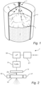
- Fig 1 schematically illustrates a radar level gauge system 1 according to an example embodiment of the present invention installed at a tank 3 containing a solid product 5.
- the solid product 5 has a non-flat surface topography
- the radar level gauge system 1 is configured to determine a topographic property of the product 5, which may, for example, be a maximum, minimum or average level of the product 5.
- the radar level gauge system 1 is controllable to deflect the transmit signal S T to hit different locations 7 on the surface of the product 5.
- a reflection signal S R resulting from reflection of the transmit signal S T at the surface of the product 5 is returned to the radar level gauge system 1. This allows the radar level gauge system 1 to determine the distance to different positions on the surface of the product, which in turn allows determination of the above-mentioned topographic property.
- the radar level gauge system 1 comprises a transceiver 9, a signal transfer element 11, a propagation member 13, an elastic system 15, an actuator 17, processing circuitry 19, and a communication interface 21.
- the transceiver 9 is configured to generate, transmit and receive electromagnetic signals, advantageously microwave signals, in a, per se , known manner.
- electromagnetic signals advantageously microwave signals
- the transceiver may, for example, operate using pulsed signals and/or a frequency sweep.
- the signal transfer element 11 is coupled to the transceiver 9 and configured to emit the above-mentioned transmit signal S T in an emission direction 23.
- the signal transfer element 11 may also capture the reflection signal S R and provide the reflection signal S R to the transceiver 9.
- the propagating member 13 is arranged and configured to propagate the transmit signal S T towards the surface of the product 5 and to propagate the reflection signal S R back towards the transceiver 9, via the signal transfer element 11.
- the propagating member 13 is movably arranged in relation to the signal transfer element 11, and is configured to deflect the transmit signal S T from the signal transfer element 11 to a plurality of different propagation directions, each propagation direction corresponding to a position of the propagating member 13 in relation to the signal transfer element 11 in a plane perpendicular to the emission direction 23.
- the elastic system 15 is coupled to the signal transfer element 11 and to the propagating member 13, and is arranged to define at least one property of an oscillating movement of the propagating member 13 in relation to the signal transfer element 11.
- movement of the propagating member 13 in relation to the signal transfer element 11 includes movement of one or both of the propagating member 13 and the signal transfer element 11, as long as there is relative movement therebetween.
- the actuator 17 is arranged to at least initiate the oscillating relative movement, between the propagating member 13 and the signal transfer element 11.
- the processing circuitry 19 is coupled to the transceiver 9 and configured to determine the above-mentioned topographic property of the product 5 based on the transmit signal S T and the reflection signal S R .
- the topographic property may be determined based on a series of timing relations between the transmit signal S T and the reflection signal S R while the above-mentioned relative oscillating movement is taking place, so that the transmit signal S T is deflected in different directions.
- a distance between a reference position at the radar level gauge system and the surface of the product 5 may then be determined for the different locations 7 on the surface of the product 5 mentioned above with reference to fig 1 .
- the communication from/to the radar level gauge system 1 via the communication interface 21 may be wireless communication, or may take place over an analog and/or digital wire-based communication channel.
- the communication channel may be a two-wire 4-20 mA loop and signals indicative of distances to the different locations 7 on the surface of the product 5 may be communicated by providing a currents corresponding to the distances on the two-wire 4-20 mA loop.
- Digital data may also be sent across such a 4-20 mA loop, using the HART protocol.
- pure digital communication protocols such as Modbus or Foundation Fieldbus may be used.
- a first example embodiment of the radar level gauge system 1 in fig 1 and fig 2 will now be described with reference to figs 3A-B .
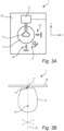
- Fig 3A is a schematic partial view of the radar level gauge system 1 facing the product 5 as seen along the emission direction 23.
- the transceiver 9 is realized as a microwave IC mounted on a carrier structure 25 in the form of a microwave circuit board, and the signal transfer element 11 comprises a patch formed in the carrier structure 25 and connected to a signal output (not shown) of the transceiver 9.
- the propagating member 13 is, in this example configuration, provided in the form of a microwave lens which at least partly has an ellipsoid shape.
- the elastic system is conceptually indicated as comprising a first spring element 27 and a second spring element 29.
- the first spring element 27 defines a first eigenfrequency ⁇ 01 of a first component of the oscillating movement of the propagating member 13 in relation to the signal transfer element 11 in a first direction (the x-direction in fig 3A )
- the second spring element 29 defines a second eigenfrequency ⁇ 02 of a second component of the oscillating movement of the propagating member 13 in relation to the signal transfer element 11 in a second direction (the y-direction in fig 3A ).
- Any elastic system for which the oscillating movement is restricted to a plane (the xy-plane) perpendicular to the emission direction 23 can be functionally represented by the first spring element 27 and the second spring element 29 in fig 3A .
- the actuator 17 is indicated as a controllable actuator that is coupled between the carrier structure 25 and the propagating member 13. It should be noted that the actuator 17 does not have to be coupled to both the carrier structure 25 and the propagating member 13 to initiate the oscillating movement, but that the actuator 17 could, for example, be coupled to the carrier structure 25 and arranged and controllable to provide impulses to the propagating member 13. Furthermore, the actuator 17 could alternatively be coupled between the elastic system 15 and a stationary structure, such as the carrier structure 25 in fig 3A .
- Fig 3B is a simplified side view of the radar level gauge system 1 in fig 3B that is mainly intended to illustrate an example configuration and arrangement of the propagating member 13 in relation to the signal transfer element 11.
- the propagating member 13 is an ellipsoidal microwave lens with a first focal point 31 and a second focal point 33.
- the signal transfer element 11 is arranged in the first focal point 31, in the absence of the above-described relative oscillating movement.
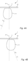
- Fig 4A shows the propagating member 13 being displaced to the left (and/or the signal transfer element 11 being displaced to the right) as compared to the situation in fig 3B , resulting in deflection of the transmit signal S T to the left in relation to the emission direction 23, so that a different location 7 on the surface of the product 5 is hit by the transmit signal S T .
- Fig 4B shows the propagating member 13 being displaced to the right (and/or the signal transfer element 11 being displaced to the left) as compared to the situation in fig 3B , resulting in deflection of the transmit signal S T to the right in relation to the emission direction 23, so that a different location 7 on the surface of the product 5 is hit by the transmit signal S T .
- Figs 5A-B schematically illustrate different example configurations of the elastic system 15 coupled to the signal transfer element 11 and to the propagating member 13 in the first example embodiment of the radar level gauge system 1 described above.
- Figs 5A-B are views of the radar level gauge system 1 as seen along the emission direction 23 from the product 5 side.
- the elastic system 15 comprises a spring wire 35, that is coupled to the carrier structure 25 and to the propagating member 13.
- the spring wire 35 is configured to define a first eigenfrequency ⁇ 01 of a first component of the oscillating movement of the propagating member 13 in relation to the signal transfer element 11 in a first direction (the x-direction), and a second eigenfrequency ⁇ 02 of a second component of the oscillating movement of the propagating member 13 in relation to the signal transfer element 11 in a second direction (the y-direction).
- the oscillating movement is restricted to the xy-plane by the configuration of the spring wire 35 and/or by a restricting structure (not shown in fig 5A ).
- fig 5B shows that the elastic system 15 instead comprises a sheet metal structure 37 that has been shaped to provide the desired properties of the oscillating movement.
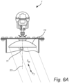
- Figs 6A-B schematically show a radar level gauge system 1 according to a second example embodiment of the present invention, where the propagating member 13 comprises a parabolic reflector.
- the parabolic reflector has a focal point, and the elastic system is configured in such a way that the signal transfer element 11 is arranged in the focal point in the absence of the relative oscillating movement, when the system is at rest.
- the relative oscillating movement will result in deflection, in this case through reflection, of the transmit signal S T (and the reflection signal S R ).
- Fig 6A shows the signal transfer element 11 being displaced to the left, resulting in deflection of the transmit signal S T to the right in relation to the emission direction 23, so that a different location 7 on the surface of the product 5 is hit by the transmit signal S T .
- Fig 6B shows the signal transfer element 11 being displaced to the right, resulting in deflection of the transmit signal S T to the left in relation to the emission direction 23, so that a different location 7 on the surface of the product 5 is hit by the transmit signal S T .
- Figs 7A-C are simulations of scanning patterns obtainable for different configurations of the elastic system 15 comprised in the radar level gauge system 1 according to embodiments of the present invention.
- fig 7A the ratio between the first ⁇ 01 and second ⁇ 02 eigenfrequencies is 1.02
- fig 7B the ratio is 1.04
- fig 7C the ratio is 1.05.
Landscapes
- Physics & Mathematics (AREA)
- Engineering & Computer Science (AREA)
- Radar, Positioning & Navigation (AREA)
- Remote Sensing (AREA)
- General Physics & Mathematics (AREA)
- Electromagnetism (AREA)
- Thermal Sciences (AREA)
- Fluid Mechanics (AREA)
- Computer Networks & Wireless Communication (AREA)
- Radar Systems Or Details Thereof (AREA)
Description
- The present invention relates to a radar level gauge system and to a method of determining a topographic property of a product.
- Radar level gauge systems are in wide use for measuring filling levels in tanks. Radar level gauging is generally performed either by means of noncontact measurement, whereby electromagnetic signals are radiated towards the product contained in the tank, or by means of contact measurement, often referred to as guided wave radar (GWR), whereby electromagnetic signals are guided towards and into the product by a probe. The electromagnetic signals are reflected at the surface of the product, and the reflected signals are received by a receiver or transceiver comprised in the radar level gauge system. Based on the transmitted and reflected signals, the distance to the surface of the product can be determined.
- More particularly, the distance to the surface of the product is generally determined based on the time between transmission of an electromagnetic signal and receipt of the reflection thereof in the interface between the atmosphere in the tank and the product contained therein. In order to determine the actual filling level of the product, the distance from a reference position to the surface is determined based on the above-mentioned time (the so-called time-of-flight) and the propagation velocity of the electromagnetic signals.
- While measuring the filling level of a liquid product may be rather straight-forward, it is more challenging to evaluate a solid product, because the surface of the product may be non-flat and/or non-horizontal. Therefore, the highest level of the solid product may not be directly below the antenna of a radar level gauge system of the non-contacting type.
- In view of this characteristic of solid products, it is known to scan the transmit signal from the transceiver of the radar level gauge system across the surface of the product, either by mechanically tilting the antenna of the radar level gauge, or by directing the emitted beam using phase array techniques.
US 2019/0107424 describes examples of both of these scanning methods. - However, both of these basic scanning methods have drawbacks. Mechanical tilting of the antenna requires a relatively costly and bulky mechanical arrangement, and phase array techniques may make it difficult to transmit sufficient power to get a reliable evaluation result.
- DE 10 2017 124996 A1 discloses a radar-based level measuring device with a first quasi-optical device, which is designed to adjust the focusing, the filtering, a beam offset and/or the beam path of the radar transmission signal towards the product in a variable manner. The quasi-optical device comprises a round holder that is rotatable about an axis, which can be rotated by a drive unit with a stepper motor, piezo-drive or an arrangement with a magnet and a spring according to the clockwork principle. Alternatively, the quasi-optical device may be displaced linearly.
-
US 2015/048963 A1 describes a radar beam deflection unit for a radar level indicator, wherein the different main emission directions of the antenna are generated using at least one prism which lies in the beam path of the level indicator and is rotated. -
US 4 219 814 A describes a scanning radar system for e.g. a blast furnace, having a microwave reflector mounted to a rotatable material-directing chute, and a non-scanning antenna, wherein as the chute moves, the surface of the product is scanned.$ -
US 2013/220011 A1 describes a fill level sensor using the radar principle, having a dielectric antenna with at least one supply element and at least one lens formed of a dielectric material. The dielectric antenna has an outer component and a spherical inner component that may be rotated, changing the main direction of radiation, thereby allowing for several measurements of different areas of the surface of the product. - In view of the above, a general object of the present invention is to provide for improved determination of a topographic property of a product, in particular a solid product.
- According to a first aspect of the present invention, it is provided a radar level gauge system for determining a topographic property of a product, the radar level gauge system comprising a transceiver for generating, transmitting and receiving electromagnetic signals; a signal transfer element coupled to the transceiver and configured to emit an electromagnetic transmit signal from the transceiver in an emission direction; a propagating member arranged and configured to propagate the transmit signal towards the surface of the product, and to propagate a reflection signal resulting from reflection of the transmit signal at the surface of the product back towards the transceiver, the propagating member being movably arranged in relation to the signal transfer element and configured to deflect the transmit signal from the signal transfer element to a plurality of different propagation directions, each propagation direction corresponding to a position of the propagating member in relation to the signal transfer element in a plane perpendicular to the emission direction; an elastic system coupled to the signal transfer element and to the propagating member, and arranged to define at least one property of an oscillating movement of one of the propagating member and the signal transfer element in relation to the other one of the propagation member and the signal transfer element, the oscillating movement being restricted from taking place in the emission direction; an actuator arranged to initiate the oscillating movement and processing circuitry coupled to the transceiver and configured to determine the topographic property based on the transmit signal and the reflection signal.
- The "transceiver" may be one functional unit capable of transmitting and receiving electromagnetic signals, or may be a system comprising separate transmitter and receiver units.
- It should be noted that the processing circuitry may be provided as one device or several devices working together.
- The present invention is based upon the realization that various topographic properties of a solid product can be determined without detailed knowledge about the scanning direction at all times.
- The present inventors have further realized that such scanning with only limited control of the scanning direction can be achieved in a cost-efficient and compact manner, without significantly reducing the transmitted power, by providing a propagating member that can redirect the transmit signal depending on the relative positioning of the propagating member and the signal transfer element, and providing for an oscillating relative movement between the signal transfer element and the propagating member.
- Hereby, predictable scanning of the surface of the product can be achieved by simple and cost-efficient means. The scanning pattern across the surface of the product can be determined by selection of the properties of the elastic system. In embodiments, the elastic system may be configured to allow tuning of its properties, providing for tuning of the scanning pattern.
- To prevent changes in in the beam shape of the transmit signal, the oscillating movement of the propagating member in relation to the signal transfer element is advantageously restricted from taking place in the emission direction, so that the oscillating movement can substantially only take place in a plane perpendicular to the emission direction.
- In embodiments where a two-dimensional scanning pattern is desired, the elastic system may define a first eigenfrequency of a first component of the oscillating movement and a second eigenfrequency, different from the first eigenfrequency, of a second component of the oscillating movement.
- According to a second aspect of the present invention, it is provided a method of determining a topographic property of a product using a radar level gauge system comprising a transceiver; a signal transfer element coupled to the transceiver; a propagating member movably arranged in relation to the signal transfer element and configured to deflect an electromagnetic signal from the signal transfer element depending on a position of the propagating member in relation to the signal transfer element; an elastic system coupled to the signal transfer element and to the propagating member; an actuator; and processing circuitry coupled to the transceiver, the method comprising: generating, by the transceiver, an electromagnetic transmit signal; emitting, by the signal transfer element, the transmit signal in an emission direction; propagating, by the propagating member, the transmit signal towards a surface of the product; propagating, by the propagating member, a reflection signal resulting from reflection of the transmit signal at the surface of the product, back towards the transceiver; receiving, by the transceiver, the reflection signal; oscillating, by the elastic system and the actuator, one of the propagating member and the signal transfer element in relation to the other one of the propagating member and the signal transfer element in a plane perpendicular to the emission direction, the oscillating movement being restricted from taking place in the emission direction, while the transmit signal is propagated towards the surface of the product and the reflection signal is propagated back towards the transceiver; and determining, by the processing circuitry, the topographic property of the product based on a timing relation between the transmit signal and the reflection signal.
- In summary, the present invention thus relates to a radar level gauge system for determining a topographic property of a product, comprising a transceiver; a signal transfer element coupled to the transceiver and configured to emit an electromagnetic transmit signal from the transceiver in an emission direction; a propagating member for propagating the transmit signal towards the surface of the product and a reflection signal back towards the transceiver, the propagating member being movably arranged in relation to the signal transfer element and configured to deflect the transmit signal; an elastic system coupled to the signal transfer element and to the propagating member, and arranged to define at least one property of an oscillating movement of the propagating member in relation to the signal transfer element; an actuator arranged to initiate the oscillating movement; and processing circuitry coupled to the transceiver for determining the topographic property based on the transmit signal and the reflection signal.
- These and other aspects of the present invention will now be described in more detail, with reference to the appended drawings showing a currently preferred embodiment of the invention, wherein:
-
Fig 1 schematically illustrates a radar level gauge system according to an example embodiment of the present invention installed at a tank containing a solid product; -
Fig 2 is a schematic block-diagram of the radar level gauge system infig 1 ; -
Fig 3A is a schematic partial view of a radar level gauge system according to a first embodiment of the present invention, as seen along the emission direction; -
Fig 3B is a schematic partial view of a radar level gauge system according to the first embodiment of the present invention, as seen along a direction perpendicular to the emission direction; -
Figs 4A-B schematically illustrate deflection of the transmit signal for two different relative positions of the signal transfer element and the propagating member for the radar level gauge system according to the first embodiment of the present invention; -
Figs 5A-B schematically illustrate different example configurations of the elastic system coupled to the signal transfer element and to the propagating member; -
Figs 6A-B schematically illustrate deflection of the transmit signal for two different relative positions of the signal transfer element and the propagating member for the radar level gauge system according to a second embodiment of the present invention; and -
Figs 7A-C are simulations of scanning patterns obtainable for different configurations of the elastic system comprised in the radar level gauge system according to embodiments of the present invention. -
Fig 1 schematically illustrates a radarlevel gauge system 1 according to an example embodiment of the present invention installed at atank 3 containing asolid product 5. As is schematically indicated infig 1 , thesolid product 5 has a non-flat surface topography, and the radarlevel gauge system 1 is configured to determine a topographic property of theproduct 5, which may, for example, be a maximum, minimum or average level of theproduct 5. - To this end, the radar
level gauge system 1 according to embodiments of the present invention is controllable to deflect the transmit signal ST to hitdifferent locations 7 on the surface of theproduct 5. As is schematically indicated infig 1 , a reflection signal SR resulting from reflection of the transmit signal ST at the surface of theproduct 5 is returned to the radarlevel gauge system 1. This allows the radarlevel gauge system 1 to determine the distance to different positions on the surface of the product, which in turn allows determination of the above-mentioned topographic property. - Referring now to
fig 2 , which is a schematic block-diagram of the radarlevel gauge system 1 infig 1 , the radarlevel gauge system 1 comprises atransceiver 9, asignal transfer element 11, apropagation member 13, anelastic system 15, anactuator 17,processing circuitry 19, and acommunication interface 21. - The
transceiver 9 is configured to generate, transmit and receive electromagnetic signals, advantageously microwave signals, in a, per se, known manner. As will be well-known to one of ordinary skill in the relevant art, the transceiver may, for example, operate using pulsed signals and/or a frequency sweep. - The
signal transfer element 11 is coupled to thetransceiver 9 and configured to emit the above-mentioned transmit signal ST in anemission direction 23. Thesignal transfer element 11 may also capture the reflection signal SR and provide the reflection signal SR to thetransceiver 9. - The propagating
member 13 is arranged and configured to propagate the transmit signal ST towards the surface of theproduct 5 and to propagate the reflection signal SR back towards thetransceiver 9, via thesignal transfer element 11. The propagatingmember 13 is movably arranged in relation to thesignal transfer element 11, and is configured to deflect the transmit signal ST from thesignal transfer element 11 to a plurality of different propagation directions, each propagation direction corresponding to a position of the propagatingmember 13 in relation to thesignal transfer element 11 in a plane perpendicular to theemission direction 23. - The
elastic system 15 is coupled to thesignal transfer element 11 and to the propagatingmember 13, and is arranged to define at least one property of an oscillating movement of the propagatingmember 13 in relation to thesignal transfer element 11. - In this context, it should be noted that movement of the propagating
member 13 in relation to thesignal transfer element 11 includes movement of one or both of the propagatingmember 13 and thesignal transfer element 11, as long as there is relative movement therebetween. - The
actuator 17 is arranged to at least initiate the oscillating relative movement, between the propagatingmember 13 and thesignal transfer element 11. - The
processing circuitry 19 is coupled to thetransceiver 9 and configured to determine the above-mentioned topographic property of theproduct 5 based on the transmit signal ST and the reflection signal SR. In particular, the topographic property may be determined based on a series of timing relations between the transmit signal ST and the reflection signal SR while the above-mentioned relative oscillating movement is taking place, so that the transmit signal ST is deflected in different directions. A distance between a reference position at the radar level gauge system and the surface of theproduct 5 may then be determined for thedifferent locations 7 on the surface of theproduct 5 mentioned above with reference tofig 1 . - The communication from/to the radar
level gauge system 1 via thecommunication interface 21 may be wireless communication, or may take place over an analog and/or digital wire-based communication channel. For instance, the communication channel may be a two-wire 4-20 mA loop and signals indicative of distances to thedifferent locations 7 on the surface of theproduct 5 may be communicated by providing a currents corresponding to the distances on the two-wire 4-20 mA loop. Digital data may also be sent across such a 4-20 mA loop, using the HART protocol. Furthermore, pure digital communication protocols such as Modbus or Foundation Fieldbus may be used. - A first example embodiment of the radar
level gauge system 1 infig 1 and fig 2 will now be described with reference tofigs 3A-B . -
Fig 3A is a schematic partial view of the radarlevel gauge system 1 facing theproduct 5 as seen along theemission direction 23. In the partly structural and partly conceptual illustration infig 3A , thetransceiver 9 is realized as a microwave IC mounted on acarrier structure 25 in the form of a microwave circuit board, and thesignal transfer element 11 comprises a patch formed in thecarrier structure 25 and connected to a signal output (not shown) of thetransceiver 9. The propagatingmember 13 is, in this example configuration, provided in the form of a microwave lens which at least partly has an ellipsoid shape. - In
fig 3A , the elastic system is conceptually indicated as comprising afirst spring element 27 and asecond spring element 29. Thefirst spring element 27 defines a first eigenfrequency ω01 of a first component of the oscillating movement of the propagatingmember 13 in relation to thesignal transfer element 11 in a first direction (the x-direction infig 3A ), and thesecond spring element 29 defines a second eigenfrequency ω02 of a second component of the oscillating movement of the propagatingmember 13 in relation to thesignal transfer element 11 in a second direction (the y-direction infig 3A ). Any elastic system for which the oscillating movement is restricted to a plane (the xy-plane) perpendicular to theemission direction 23 can be functionally represented by thefirst spring element 27 and thesecond spring element 29 infig 3A . - In the example configuration in
fig 3A , theactuator 17 is indicated as a controllable actuator that is coupled between thecarrier structure 25 and the propagatingmember 13. It should be noted that theactuator 17 does not have to be coupled to both thecarrier structure 25 and the propagatingmember 13 to initiate the oscillating movement, but that theactuator 17 could, for example, be coupled to thecarrier structure 25 and arranged and controllable to provide impulses to the propagatingmember 13. Furthermore, theactuator 17 could alternatively be coupled between theelastic system 15 and a stationary structure, such as thecarrier structure 25 infig 3A . -
Fig 3B is a simplified side view of the radarlevel gauge system 1 infig 3B that is mainly intended to illustrate an example configuration and arrangement of the propagatingmember 13 in relation to thesignal transfer element 11. In this example configuration and arrangement, the propagatingmember 13 is an ellipsoidal microwave lens with a firstfocal point 31 and a secondfocal point 33. As is schematically illustrated infig 3B , thesignal transfer element 11 is arranged in the firstfocal point 31, in the absence of the above-described relative oscillating movement. - As mentioned above, the relative oscillating movement will result in deflection, in this case through refraction, of the transmit signal ST (and the reflection signal SR).
Fig 4A shows the propagatingmember 13 being displaced to the left (and/or thesignal transfer element 11 being displaced to the right) as compared to the situation infig 3B , resulting in deflection of the transmit signal ST to the left in relation to theemission direction 23, so that adifferent location 7 on the surface of theproduct 5 is hit by the transmit signal ST.Fig 4B shows the propagatingmember 13 being displaced to the right (and/or thesignal transfer element 11 being displaced to the left) as compared to the situation infig 3B , resulting in deflection of the transmit signal ST to the right in relation to theemission direction 23, so that adifferent location 7 on the surface of theproduct 5 is hit by the transmit signal ST. -
Figs 5A-B schematically illustrate different example configurations of theelastic system 15 coupled to thesignal transfer element 11 and to the propagatingmember 13 in the first example embodiment of the radarlevel gauge system 1 described above.Figs 5A-B are views of the radarlevel gauge system 1 as seen along theemission direction 23 from theproduct 5 side. - In the first example configuration in
fig 5A , theelastic system 15 comprises aspring wire 35, that is coupled to thecarrier structure 25 and to the propagatingmember 13. Thespring wire 35 is configured to define a first eigenfrequency ω01 of a first component of the oscillating movement of the propagatingmember 13 in relation to thesignal transfer element 11 in a first direction (the x-direction), and a second eigenfrequency ω02 of a second component of the oscillating movement of the propagatingmember 13 in relation to thesignal transfer element 11 in a second direction (the y-direction). The oscillating movement is restricted to the xy-plane by the configuration of thespring wire 35 and/or by a restricting structure (not shown infig 5A ). - To illustrate one of many possible alternatives to the
spring wire 35 infig 5A, fig 5B shows that theelastic system 15 instead comprises asheet metal structure 37 that has been shaped to provide the desired properties of the oscillating movement. -
Figs 6A-B schematically show a radarlevel gauge system 1 according to a second example embodiment of the present invention, where the propagatingmember 13 comprises a parabolic reflector. The parabolic reflector has a focal point, and the elastic system is configured in such a way that thesignal transfer element 11 is arranged in the focal point in the absence of the relative oscillating movement, when the system is at rest. - Also for this embodiment of the radar
level gauge system 1, the relative oscillating movement will result in deflection, in this case through reflection, of the transmit signal ST (and the reflection signal SR).Fig 6A shows thesignal transfer element 11 being displaced to the left, resulting in deflection of the transmit signal ST to the right in relation to theemission direction 23, so that adifferent location 7 on the surface of theproduct 5 is hit by the transmit signal ST.Fig 6B shows thesignal transfer element 11 being displaced to the right, resulting in deflection of the transmit signal ST to the left in relation to theemission direction 23, so that adifferent location 7 on the surface of theproduct 5 is hit by the transmit signal ST. - Although it is indicated in
figs 6A-B that thesignal transfer element 11 is being displaced, it could be possible to instead displace thepropagation member 13, or both thesignal transfer element 11 and thepropagation member 13. - To get a desired coverage of the surface of the
product 5, it may be desirable to configure theelastic system 15 to define different first ω01 and second ω02 eigenfrequencies.Figs 7A-C are simulations of scanning patterns obtainable for different configurations of theelastic system 15 comprised in the radarlevel gauge system 1 according to embodiments of the present invention. Infig 7A , the ratio between the first ω01 and second ω02 eigenfrequencies is 1.02, infig 7B , the ratio is 1.04, and infig 7C , the ratio is 1.05. - The person skilled in the art realizes that the present invention by no means is limited to the preferred embodiments described above. On the contrary, many modifications and variations are possible within the scope of the appended claims.
Claims (11)
- A radar level gauge system (1) for determining a topographic property of a product (5), the radar level gauge system comprising:a transceiver (9) for generating, transmitting and receiving electromagnetic signals;a signal transfer element (11) coupled to the transceiver and configured to emit an electromagnetic transmit signal from the transceiver in an emission direction (23);a propagating member (13) arranged and configured to propagate the transmit signal towards the surface of the product, and to propagate a reflection signal resulting from reflection of the transmit signal at the surface of the product back towards the transceiver, the propagating member (13) being movably arranged in relation to the signal transfer element (11) and configured to deflect the transmit signal from the signal transfer element to a plurality of different propagation directions, each propagation direction corresponding to a position of the propagating member in relation to the signal transfer element in a plane perpendicular to the emission direction;an elastic system (15) coupled to the signal transfer element and to the propagating member, and arranged to define at least one property of an oscillating movement of one of the propagating member and the signal transfer element in relation to the other one of the propagating member and the signal transfer element, the oscillating movement being restricted from taking place in the emission direction (23);an actuator (17) arranged to initiate the oscillating movement; andprocessing circuitry (19) coupled to the transceiver (9) and configured to determine the topographic property based on the transmit signal and the reflection signal.
- The radar level gauge system according to claim 1, wherein the elastic system (15) defines a first eigenfrequency of a first component of the oscillating movement and a second eigenfrequency, different from the first eigenfrequency, of a second component of the oscillating movement.
- The radar level gauge system according to claim 1 or 2, wherein the elastic system (15) comprises a first portion fixed to the signal transfer element (11) and second portion fixed to the propagating member (13); and a spring elemen (27, 29) elastically connecting the first portion and the second portion.
- The radar level gauge system according to any one of the preceding claims, wherein the propagating member (13) comprises a microwave lens.
- The radar level gauge system according to claim 4, wherein the microwave lens at least partly has an ellipsoid shape.
- The radar level gauge system according to claim 4 or 5, wherein:the microwave lens has a focal point (33); andthe elastic system is configured in such a way that the signal transfer element is arranged in the focal point in the absence of the oscillating movement of the propagating member in relation to the signal transfer element.
- The radar level gauge system according to any one of the preceding claims, wherein the propagating member (13) comprises a parabolic reflector.
- The radar level gauge system according to claim 7, wherein:the parabolic reflector has a focal point; andthe elastic system is configured in such a way that the signal transfer element is arranged in the focal point in the absence of the oscillating movement of the propagating member in relation to the signal transfer element.
- The radar level gauge system according to any one of the preceding claims, wherein the signal transfer element (11) remains stationary when the oscillating movement is initiated.
- The radar level gauge system according to any one of claims 1 to 8, wherein the propagating member (13) remains stationary when the oscillating movement is initiated.
- A method of determining a topographic property of a product (5) using a radar level gauge system (1) comprising a transceiver (9);a signal transfer element (11) coupled to the transceiver; a propagating member (13) movably arranged in relation to the signal transfer element and configured to deflect an electromagnetic signal from the signal transfer element depending on a position of the propagating member in relation to the signal transfer element;an elastic system (15) coupled to the signal transfer element and to the propagating member; an actuator (17);and processing circuitry (19) coupled to the transceiver, the method comprising:generating, by the transceiver, an electromagnetic transmit signal;emitting, by the signal transfer element, the transmit signal in an emission direction (23);propagating, by the propagating member, the transmit signal towards a surface of the product;propagating, by the propagating member, a reflection signal resulting from reflection of the transmit signal at the surface of the product, back towards the transceiver;receiving, by the transceiver, the reflection signal;oscillating, by the elastic system and the actuator, one of the propagating member and the signal transfer element in relation to the other one of the propagating member and the signal transfer element in a plane perpendicular to the emission direction (23), the oscillating movement being restricted from taking place in the emission direction (23), while the transmit signal is propagated towards the surface of the product and the reflection signal is propagated back towards the transceiver; anddetermining, by the processing circuitry, the topographic property of the product based on a timing relation between the transmit signal and the reflection signal.
Priority Applications (4)
| Application Number | Priority Date | Filing Date | Title |
|---|---|---|---|
| EP21156859.7A EP4043841B1 (en) | 2021-02-12 | 2021-02-12 | Radar level gauge with elastic system |
| EP22153199.9A EP4043842B1 (en) | 2021-02-12 | 2022-01-25 | Radar level gauge with elastic system |
| US17/588,486 US12276537B2 (en) | 2021-02-12 | 2022-01-31 | Radar level gauge with elastic system |
| CN202210122409.5A CN114923537A (en) | 2021-02-12 | 2022-02-09 | Radar level gauge system and method for determining a topographical property of a product |
Applications Claiming Priority (1)
| Application Number | Priority Date | Filing Date | Title |
|---|---|---|---|
| EP21156859.7A EP4043841B1 (en) | 2021-02-12 | 2021-02-12 | Radar level gauge with elastic system |
Publications (2)
| Publication Number | Publication Date |
|---|---|
| EP4043841A1 EP4043841A1 (en) | 2022-08-17 |
| EP4043841B1 true EP4043841B1 (en) | 2024-09-25 |
Family
ID=74595171
Family Applications (2)
| Application Number | Title | Priority Date | Filing Date |
|---|---|---|---|
| EP21156859.7A Active EP4043841B1 (en) | 2021-02-12 | 2021-02-12 | Radar level gauge with elastic system |
| EP22153199.9A Active EP4043842B1 (en) | 2021-02-12 | 2022-01-25 | Radar level gauge with elastic system |
Family Applications After (1)
| Application Number | Title | Priority Date | Filing Date |
|---|---|---|---|
| EP22153199.9A Active EP4043842B1 (en) | 2021-02-12 | 2022-01-25 | Radar level gauge with elastic system |
Country Status (3)
| Country | Link |
|---|---|
| US (1) | US12276537B2 (en) |
| EP (2) | EP4043841B1 (en) |
| CN (1) | CN114923537A (en) |
Families Citing this family (1)
| Publication number | Priority date | Publication date | Assignee | Title |
|---|---|---|---|---|
| WO2025165262A1 (en) * | 2024-01-29 | 2025-08-07 | Акционерное общество "ЛИМАКО" | Radar instrument for measuring the level and volume of fluent materials |
Family Cites Families (18)
| Publication number | Priority date | Publication date | Assignee | Title |
|---|---|---|---|---|
| FR1095342A (en) * | 1953-10-09 | 1955-06-01 | Thomson Houston Comp Francaise | Advanced radar aerial |
| US4041500A (en) * | 1976-05-12 | 1977-08-09 | The United States Of America As Represented By The Secretary Of The Navy | Line scan radar antenna using a single motor |
| US4219814A (en) * | 1978-12-26 | 1980-08-26 | Rca Corporation | Scanning radar |
| JP3186622B2 (en) | 1997-01-07 | 2001-07-11 | 株式会社村田製作所 | Antenna device and transmitting / receiving device |
| DE102005036715A1 (en) * | 2005-08-04 | 2007-02-15 | Vega Grieshaber Kg | Fill level radar for determining fill level in tank, has separation element arranged directly at aerial for isolating aerial from feed device |
| DE102007056329A1 (en) * | 2007-11-22 | 2009-05-28 | Robert Bosch Gmbh | Angle-resolving radar sensor |
| DE102011007372B4 (en) * | 2011-04-14 | 2023-05-04 | Endress+Hauser SE+Co. KG | Calibration and/or monitoring method for FMCW radar level gauges |
| DE102012003398B4 (en) * | 2012-02-23 | 2015-06-25 | Krohne Messtechnik Gmbh | According to the radar principle working level gauge |
| EP2837950B1 (en) * | 2013-08-14 | 2016-05-04 | VEGA Grieshaber KG | Radar beam deflection unit for a fill level radar |
| CN105981222A (en) * | 2014-02-17 | 2016-09-28 | 日本电气株式会社 | Antenna device and antenna device control method |
| DE102014013003A1 (en) * | 2014-08-29 | 2016-03-03 | Audi Ag | Radar sensor, in particular for a motor vehicle, and motor vehicle |
| EP3287754B1 (en) * | 2015-04-20 | 2019-08-07 | Panasonic Intellectual Property Management Co., Ltd. | Vibration visualization element, vibration measurement system, and method for measuring vibration |
| WO2017006524A1 (en) * | 2015-07-09 | 2017-01-12 | 日本電気株式会社 | Beam tilt angle control device, antenna system, wireless communication device, and beam tilt angle control method |
| CN107272014B (en) | 2017-08-05 | 2023-12-12 | 广州市杜格科技有限公司 | Solid two-dimensional scanning laser radar and scanning method thereof |
| EP3467449B1 (en) | 2017-10-06 | 2020-07-08 | VEGA Grieshaber KG | Radar fill level measuring device with high frequency amplifier |
| DE102017124996A1 (en) * | 2017-10-25 | 2019-04-25 | Endress+Hauser SE+Co. KG | Radar-based level gauge |
| US10509198B1 (en) * | 2018-12-07 | 2019-12-17 | Didi Research America, Llc | Lever system for driving mirrors of a lidar transmitter |
| WO2020125977A1 (en) * | 2018-12-19 | 2020-06-25 | Rosemount Tank Radar Ab | Proof test of radar level gauge system |
-
2021
- 2021-02-12 EP EP21156859.7A patent/EP4043841B1/en active Active
-
2022
- 2022-01-25 EP EP22153199.9A patent/EP4043842B1/en active Active
- 2022-01-31 US US17/588,486 patent/US12276537B2/en active Active
- 2022-02-09 CN CN202210122409.5A patent/CN114923537A/en active Pending
Also Published As
| Publication number | Publication date |
|---|---|
| US12276537B2 (en) | 2025-04-15 |
| EP4043842A1 (en) | 2022-08-17 |
| US20220260406A1 (en) | 2022-08-18 |
| EP4043841A1 (en) | 2022-08-17 |
| CN114923537A (en) | 2022-08-19 |
| EP4043842B1 (en) | 2025-02-26 |
Similar Documents
| Publication | Publication Date | Title |
|---|---|---|
| US6822612B2 (en) | Antenna device, communication apparatus and radar module | |
| US7861600B2 (en) | Apparatus for ascertaining and/or monitoring fill level and/or flow of a medium | |
| US7474256B2 (en) | Position detecting system, and transmitting and receiving apparatuses for the position detecting system | |
| US8643536B2 (en) | Radio frequency positioning system for vehicles | |
| US20150253177A1 (en) | Fill-Level Measuring Device | |
| CN105980817A (en) | Determining a topology of the surface of a material filled into a container | |
| CN115421131B (en) | Equivalent multi-position dead-angle-free electromagnetic wave 3D scanning radar and material measuring method | |
| CN107078400A (en) | Surface topology determination of filled materials using uniform line scan | |
| CN114609625B (en) | Reflection type continuous rotation radar scanning device, measurement system and material measurement method | |
| CN104374446A (en) | Radar beam deflection unit for a radar level indicator | |
| US7248341B2 (en) | Apparatus and method for oscillating a transmitted laser beam of light within the field of view (FOV) of a light receiving system | |
| EP4043842B1 (en) | Radar level gauge with elastic system | |
| CN111801592A (en) | 3D and 4D mapping of space using microwave and millimeter wave parallax | |
| US5841392A (en) | Pulse-echo ranging system with improved target | |
| WO2019243485A1 (en) | Radar level gauge | |
| CN100547431C (en) | Radar Installation Direction Adjustment Method and Adjustment Device | |
| EP4001959A1 (en) | Radar level gauging apparatus | |
| EP4243205B1 (en) | An antenna for a radar apparatus | |
| US20200158818A1 (en) | Radar sensor | |
| CN216012139U (en) | Displacement measuring device | |
| EP4481340A1 (en) | Vibration estimation system with aiming arrangement | |
| US20080083281A1 (en) | Process for measurement of the level of a medium in a container based on the radar principle | |
| EP4425214A1 (en) | Method for and system operating an underground mining and tunneling machine | |
| CN215491512U (en) | Single antenna displacement measuring device | |
| JP3772191B2 (en) | Measuring device using radio wave reflector |
Legal Events
| Date | Code | Title | Description |
|---|---|---|---|
| PUAI | Public reference made under article 153(3) epc to a published international application that has entered the european phase |
Free format text: ORIGINAL CODE: 0009012 |
|
| STAA | Information on the status of an ep patent application or granted ep patent |
Free format text: STATUS: THE APPLICATION HAS BEEN PUBLISHED |
|
| AK | Designated contracting states |
Kind code of ref document: A1 Designated state(s): AL AT BE BG CH CY CZ DE DK EE ES FI FR GB GR HR HU IE IS IT LI LT LU LV MC MK MT NL NO PL PT RO RS SE SI SK SM TR |
|
| STAA | Information on the status of an ep patent application or granted ep patent |
Free format text: STATUS: REQUEST FOR EXAMINATION WAS MADE |
|
| 17P | Request for examination filed |
Effective date: 20230215 |
|
| RBV | Designated contracting states (corrected) |
Designated state(s): AL AT BE BG CH CY CZ DE DK EE ES FI FR GB GR HR HU IE IS IT LI LT LU LV MC MK MT NL NO PL PT RO RS SE SI SK SM TR |
|
| RIC1 | Information provided on ipc code assigned before grant |
Ipc: G01S 13/88 20060101ALI20240314BHEP Ipc: G01S 13/42 20060101ALI20240314BHEP Ipc: G01S 7/02 20060101ALI20240314BHEP Ipc: H01Q 1/22 20060101ALI20240314BHEP Ipc: H01Q 3/12 20060101ALI20240314BHEP Ipc: G01F 23/284 20060101AFI20240314BHEP |
|
| GRAP | Despatch of communication of intention to grant a patent |
Free format text: ORIGINAL CODE: EPIDOSNIGR1 |
|
| STAA | Information on the status of an ep patent application or granted ep patent |
Free format text: STATUS: GRANT OF PATENT IS INTENDED |
|
| INTG | Intention to grant announced |
Effective date: 20240419 |
|
| GRAS | Grant fee paid |
Free format text: ORIGINAL CODE: EPIDOSNIGR3 |
|
| GRAA | (expected) grant |
Free format text: ORIGINAL CODE: 0009210 |
|
| STAA | Information on the status of an ep patent application or granted ep patent |
Free format text: STATUS: THE PATENT HAS BEEN GRANTED |
|
| AK | Designated contracting states |
Kind code of ref document: B1 Designated state(s): AL AT BE BG CH CY CZ DE DK EE ES FI FR GB GR HR HU IE IS IT LI LT LU LV MC MK MT NL NO PL PT RO RS SE SI SK SM TR |
|
| REG | Reference to a national code |
Ref country code: GB Ref legal event code: FG4D |
|
| REG | Reference to a national code |
Ref country code: CH Ref legal event code: EP |
|
| REG | Reference to a national code |
Ref country code: DE Ref legal event code: R096 Ref document number: 602021019145 Country of ref document: DE |
|
| REG | Reference to a national code |
Ref country code: IE Ref legal event code: FG4D |
|
| REG | Reference to a national code |
Ref country code: LT Ref legal event code: MG9D |
|
| PG25 | Lapsed in a contracting state [announced via postgrant information from national office to epo] |
Ref country code: NO Free format text: LAPSE BECAUSE OF FAILURE TO SUBMIT A TRANSLATION OF THE DESCRIPTION OR TO PAY THE FEE WITHIN THE PRESCRIBED TIME-LIMIT Effective date: 20241225 |
|
| PG25 | Lapsed in a contracting state [announced via postgrant information from national office to epo] |
Ref country code: GR Free format text: LAPSE BECAUSE OF FAILURE TO SUBMIT A TRANSLATION OF THE DESCRIPTION OR TO PAY THE FEE WITHIN THE PRESCRIBED TIME-LIMIT Effective date: 20241226 Ref country code: FI Free format text: LAPSE BECAUSE OF FAILURE TO SUBMIT A TRANSLATION OF THE DESCRIPTION OR TO PAY THE FEE WITHIN THE PRESCRIBED TIME-LIMIT Effective date: 20240925 |
|
| PG25 | Lapsed in a contracting state [announced via postgrant information from national office to epo] |
Ref country code: BG Free format text: LAPSE BECAUSE OF FAILURE TO SUBMIT A TRANSLATION OF THE DESCRIPTION OR TO PAY THE FEE WITHIN THE PRESCRIBED TIME-LIMIT Effective date: 20240925 |
|
| PG25 | Lapsed in a contracting state [announced via postgrant information from national office to epo] |
Ref country code: LV Free format text: LAPSE BECAUSE OF FAILURE TO SUBMIT A TRANSLATION OF THE DESCRIPTION OR TO PAY THE FEE WITHIN THE PRESCRIBED TIME-LIMIT Effective date: 20240925 |
|
| PG25 | Lapsed in a contracting state [announced via postgrant information from national office to epo] |
Ref country code: RS Free format text: LAPSE BECAUSE OF FAILURE TO SUBMIT A TRANSLATION OF THE DESCRIPTION OR TO PAY THE FEE WITHIN THE PRESCRIBED TIME-LIMIT Effective date: 20241225 |
|
| REG | Reference to a national code |
Ref country code: NL Ref legal event code: MP Effective date: 20240925 |
|
| PG25 | Lapsed in a contracting state [announced via postgrant information from national office to epo] |
Ref country code: RS Free format text: LAPSE BECAUSE OF FAILURE TO SUBMIT A TRANSLATION OF THE DESCRIPTION OR TO PAY THE FEE WITHIN THE PRESCRIBED TIME-LIMIT Effective date: 20241225 Ref country code: NO Free format text: LAPSE BECAUSE OF FAILURE TO SUBMIT A TRANSLATION OF THE DESCRIPTION OR TO PAY THE FEE WITHIN THE PRESCRIBED TIME-LIMIT Effective date: 20241225 Ref country code: LV Free format text: LAPSE BECAUSE OF FAILURE TO SUBMIT A TRANSLATION OF THE DESCRIPTION OR TO PAY THE FEE WITHIN THE PRESCRIBED TIME-LIMIT Effective date: 20240925 Ref country code: GR Free format text: LAPSE BECAUSE OF FAILURE TO SUBMIT A TRANSLATION OF THE DESCRIPTION OR TO PAY THE FEE WITHIN THE PRESCRIBED TIME-LIMIT Effective date: 20241226 Ref country code: FI Free format text: LAPSE BECAUSE OF FAILURE TO SUBMIT A TRANSLATION OF THE DESCRIPTION OR TO PAY THE FEE WITHIN THE PRESCRIBED TIME-LIMIT Effective date: 20240925 Ref country code: BG Free format text: LAPSE BECAUSE OF FAILURE TO SUBMIT A TRANSLATION OF THE DESCRIPTION OR TO PAY THE FEE WITHIN THE PRESCRIBED TIME-LIMIT Effective date: 20240925 |
|
| REG | Reference to a national code |
Ref country code: AT Ref legal event code: MK05 Ref document number: 1726975 Country of ref document: AT Kind code of ref document: T Effective date: 20240925 |
|
| PG25 | Lapsed in a contracting state [announced via postgrant information from national office to epo] |
Ref country code: NL Free format text: LAPSE BECAUSE OF FAILURE TO SUBMIT A TRANSLATION OF THE DESCRIPTION OR TO PAY THE FEE WITHIN THE PRESCRIBED TIME-LIMIT Effective date: 20240925 |
|
| PG25 | Lapsed in a contracting state [announced via postgrant information from national office to epo] |
Ref country code: PT Free format text: LAPSE BECAUSE OF FAILURE TO SUBMIT A TRANSLATION OF THE DESCRIPTION OR TO PAY THE FEE WITHIN THE PRESCRIBED TIME-LIMIT Effective date: 20250127 Ref country code: IS Free format text: LAPSE BECAUSE OF FAILURE TO SUBMIT A TRANSLATION OF THE DESCRIPTION OR TO PAY THE FEE WITHIN THE PRESCRIBED TIME-LIMIT Effective date: 20250125 |
|
| PG25 | Lapsed in a contracting state [announced via postgrant information from national office to epo] |
Ref country code: RO Free format text: LAPSE BECAUSE OF FAILURE TO SUBMIT A TRANSLATION OF THE DESCRIPTION OR TO PAY THE FEE WITHIN THE PRESCRIBED TIME-LIMIT Effective date: 20240925 Ref country code: SM Free format text: LAPSE BECAUSE OF FAILURE TO SUBMIT A TRANSLATION OF THE DESCRIPTION OR TO PAY THE FEE WITHIN THE PRESCRIBED TIME-LIMIT Effective date: 20240925 |
|
| PG25 | Lapsed in a contracting state [announced via postgrant information from national office to epo] |
Ref country code: ES Free format text: LAPSE BECAUSE OF FAILURE TO SUBMIT A TRANSLATION OF THE DESCRIPTION OR TO PAY THE FEE WITHIN THE PRESCRIBED TIME-LIMIT Effective date: 20240925 |
|
| PG25 | Lapsed in a contracting state [announced via postgrant information from national office to epo] |
Ref country code: EE Free format text: LAPSE BECAUSE OF FAILURE TO SUBMIT A TRANSLATION OF THE DESCRIPTION OR TO PAY THE FEE WITHIN THE PRESCRIBED TIME-LIMIT Effective date: 20240925 Ref country code: AT Free format text: LAPSE BECAUSE OF FAILURE TO SUBMIT A TRANSLATION OF THE DESCRIPTION OR TO PAY THE FEE WITHIN THE PRESCRIBED TIME-LIMIT Effective date: 20240925 |
|
| PG25 | Lapsed in a contracting state [announced via postgrant information from national office to epo] |
Ref country code: PL Free format text: LAPSE BECAUSE OF FAILURE TO SUBMIT A TRANSLATION OF THE DESCRIPTION OR TO PAY THE FEE WITHIN THE PRESCRIBED TIME-LIMIT Effective date: 20240925 Ref country code: CZ Free format text: LAPSE BECAUSE OF FAILURE TO SUBMIT A TRANSLATION OF THE DESCRIPTION OR TO PAY THE FEE WITHIN THE PRESCRIBED TIME-LIMIT Effective date: 20240925 |
|
| PG25 | Lapsed in a contracting state [announced via postgrant information from national office to epo] |
Ref country code: IT Free format text: LAPSE BECAUSE OF FAILURE TO SUBMIT A TRANSLATION OF THE DESCRIPTION OR TO PAY THE FEE WITHIN THE PRESCRIBED TIME-LIMIT Effective date: 20240925 Ref country code: SK Free format text: LAPSE BECAUSE OF FAILURE TO SUBMIT A TRANSLATION OF THE DESCRIPTION OR TO PAY THE FEE WITHIN THE PRESCRIBED TIME-LIMIT Effective date: 20240925 |
|
| REG | Reference to a national code |
Ref country code: DE Ref legal event code: R097 Ref document number: 602021019145 Country of ref document: DE |
|
| PG25 | Lapsed in a contracting state [announced via postgrant information from national office to epo] |
Ref country code: DK Free format text: LAPSE BECAUSE OF FAILURE TO SUBMIT A TRANSLATION OF THE DESCRIPTION OR TO PAY THE FEE WITHIN THE PRESCRIBED TIME-LIMIT Effective date: 20240925 |
|
| PLBE | No opposition filed within time limit |
Free format text: ORIGINAL CODE: 0009261 |
|
| STAA | Information on the status of an ep patent application or granted ep patent |
Free format text: STATUS: NO OPPOSITION FILED WITHIN TIME LIMIT |
|
| 26N | No opposition filed |
Effective date: 20250626 |
|
| PG25 | Lapsed in a contracting state [announced via postgrant information from national office to epo] |
Ref country code: SE Free format text: LAPSE BECAUSE OF FAILURE TO SUBMIT A TRANSLATION OF THE DESCRIPTION OR TO PAY THE FEE WITHIN THE PRESCRIBED TIME-LIMIT Effective date: 20240925 |
|
| PG25 | Lapsed in a contracting state [announced via postgrant information from national office to epo] |
Ref country code: MC Free format text: LAPSE BECAUSE OF FAILURE TO SUBMIT A TRANSLATION OF THE DESCRIPTION OR TO PAY THE FEE WITHIN THE PRESCRIBED TIME-LIMIT Effective date: 20240925 |
|
| REG | Reference to a national code |
Ref country code: CH Ref legal event code: PL |
|
| PG25 | Lapsed in a contracting state [announced via postgrant information from national office to epo] |
Ref country code: LU Free format text: LAPSE BECAUSE OF NON-PAYMENT OF DUE FEES Effective date: 20250212 |
|
| PG25 | Lapsed in a contracting state [announced via postgrant information from national office to epo] |
Ref country code: CH Free format text: LAPSE BECAUSE OF NON-PAYMENT OF DUE FEES Effective date: 20250228 |
|
| GBPC | Gb: european patent ceased through non-payment of renewal fee |
Effective date: 20250212 |
|
| REG | Reference to a national code |
Ref country code: BE Ref legal event code: MM Effective date: 20250228 |
|
| PG25 | Lapsed in a contracting state [announced via postgrant information from national office to epo] |
Ref country code: GB Free format text: LAPSE BECAUSE OF NON-PAYMENT OF DUE FEES Effective date: 20250212 |
|
| PG25 | Lapsed in a contracting state [announced via postgrant information from national office to epo] |
Ref country code: HR Free format text: LAPSE BECAUSE OF FAILURE TO SUBMIT A TRANSLATION OF THE DESCRIPTION OR TO PAY THE FEE WITHIN THE PRESCRIBED TIME-LIMIT Effective date: 20240925 Ref country code: FR Free format text: LAPSE BECAUSE OF NON-PAYMENT OF DUE FEES Effective date: 20250228 |
|
| PG25 | Lapsed in a contracting state [announced via postgrant information from national office to epo] |
Ref country code: BE Free format text: LAPSE BECAUSE OF NON-PAYMENT OF DUE FEES Effective date: 20250228 |
|
| PG25 | Lapsed in a contracting state [announced via postgrant information from national office to epo] |
Ref country code: IE Free format text: LAPSE BECAUSE OF NON-PAYMENT OF DUE FEES Effective date: 20250212 |
|
| PGFP | Annual fee paid to national office [announced via postgrant information from national office to epo] |
Ref country code: DE Payment date: 20260121 Year of fee payment: 6 |