EP4043839B1 - Inline-wandlergehäuseanordnung - Google Patents
Inline-wandlergehäuseanordnung Download PDFInfo
- Publication number
- EP4043839B1 EP4043839B1 EP22153492.8A EP22153492A EP4043839B1 EP 4043839 B1 EP4043839 B1 EP 4043839B1 EP 22153492 A EP22153492 A EP 22153492A EP 4043839 B1 EP4043839 B1 EP 4043839B1
- Authority
- EP
- European Patent Office
- Prior art keywords
- transducer
- inline
- assembly
- square
- meter body
- Prior art date
- Legal status (The legal status is an assumption and is not a legal conclusion. Google has not performed a legal analysis and makes no representation as to the accuracy of the status listed.)
- Active
Links
Images

Classifications
-
- G—PHYSICS
- G01—MEASURING; TESTING
- G01F—MEASURING VOLUME, VOLUME FLOW, MASS FLOW OR LIQUID LEVEL; METERING BY VOLUME
- G01F15/00—Details of, or accessories for, apparatus of groups G01F1/00 - G01F13/00 insofar as such details or appliances are not adapted to particular types of such apparatus
- G01F15/18—Supports or connecting means for meters
-
- G—PHYSICS
- G01—MEASURING; TESTING
- G01F—MEASURING VOLUME, VOLUME FLOW, MASS FLOW OR LIQUID LEVEL; METERING BY VOLUME
- G01F1/00—Measuring the volume flow or mass flow of fluid or fluent solid material wherein the fluid passes through a meter in a continuous flow
- G01F1/66—Measuring the volume flow or mass flow of fluid or fluent solid material wherein the fluid passes through a meter in a continuous flow by measuring frequency, phase shift or propagation time of electromagnetic or other waves, e.g. using ultrasonic flowmeters
- G01F1/662—Constructional details
Definitions
- Embodiments are related to fluid flow meters. More particularly, embodiments are related to a flow meter adapted to securely place and hold an inline transducer housing assembly within fluid flowing through a conduit. Embodiments are also related to use of an injection mould tool utilizing 3D printed inserts to render an inline transducer housing assembly body.
- Flow meters are sophisticated measuring devices that employ a range of technologies designed to quantify the rate or volume of a moving fluid, either liquid or gas, in an open or closed conduit.
- the type of flow meter used will vary by application, but coriolis, differential pressure, magmeter, electromagnetic, oval gear, thermal, paddlewheel, positive displacement and ultrasonic are the most commonly used technologies.
- Ultrasonic flow meters use sound waves as a reliable, accurate and maintenance free method to measure the velocity of a fluid from which the volumetric flow rate can be calculated. They feature no moving parts making them more reliable and accurate while providing maintenance-free operation. Since ultrasonic signals can also penetrate solid materials, the transducers can be mounted onto the outside of the pipe offering completely non-invasive measurement eliminating chemical compatibility issues, pressure restrictions, and pressure loss. Inline mounting of transducers, however, can provide the most accurate measurement of fluid flow.
- FR3035513A1 discloses a device for measuring the flow velocity of a fluid comprising a body, at least one ultrasonic transducer comprising a first end called the proximal end, assembled by a connection of embedded in said body and extending projecting from said body, in a longitudinal direction, as far as a second end, called distal end, of the transducer, characterized in that said distal end is assembled to the body by an assembly rigidly fixing the distal end relative to the body in at least one direction orthogonal to said longitudinal direction.
- Embodiments are presented to achieve accurate inline fluid flow measurement over a long period while minimizing degradation of measurement data quality.
- Embodiments presented are also to achieve accurate inline fluid flow measurement over a long period while minimizing degradation of quality by using ultrasonic flow-rate sensing technology.
- a flow tube to support an inline transducer housing assembly can be fabricated by using a liquid cooled tool that can include a channel that can accept a core that can enable formation of a port to then accept a sensor assembly, and can also enable formation of a notch to help stabilize the sensor assembly in alignment with fluid flow.
- a resulting assembly from fabrication can include a circular shelf formed on the housing assembly adapted to receive a transducer assembly that interfaces in a complimentary manner with a circular ledge of a circular head section of the transducer assembly, a portal formed between the circular shelf and an inner surface of the housing adapted to interface in a complimentary manner with an alignment section of the transducer, and a notch formed in the inner surface of the flow tube opposite the portal to interface with a positioner formed on and extending from a transducer holder operating to secure the transducer holder flow alignment.
- an inline transducer meter assembly having an inlet and an outlet for fluid flowing through the inline transducer meter assembly from the inlet to the outlet
- a circular shelf integrated in an inline transducer meter body adapted to receive a transducer assembly that interfaces in a complimentary manner with a circular ledge of a circular head section of the transducer assembly
- a square or rectangular portal formed between the circular shelf and an inner surface of the inline transducer meter body adapted to interface in a complimentary manner with an alignment section of the transducer assembly having a reduced surface area to reduce upshot force on the alignment section by fluid flowing through the inline transducer housing assembly body and past the square or rectangular portal
- a method for fabricating an inline transducer meter body with 3D moulding includes steps of providing a fabrication tool that can be mounted to a 3D moulding machine, said fabrication tool having a moving section formed by a 3D printer and including at least one cooling channel therein for accepting fluid coolant to keep the surface cool during fabrication of the inline transducer meter body, wherein the fabrication tool has at least one channel formed through the surface that is configured to receive a square or rectangular core therein to prevent material from being placed in the channel during fabrication, adding material onto the surface using moulding while cooling the surface via coolant circulating through the at least one tool channel, removing the core from the fabrication tool, and removing the fabrication tool from the material added onto the surface of the fabrication tool.
- an inline transducer meter body having an inner surface formed by the surface of the fabrication tool, an inlet and an outlet, a circular shelf integrated in an inline transducer meter body adapted to receive a transducer assembly that interfaces in a complimentary manner with a circular ledge of a circular head section of the transducer assembly a square or rectangular portal formed between the circular shelf and an inner surface of the inline transducer meter body adapted to interface in a complimentary manner with an alignment section of the transducer assembly having a reduced surface area to reduce upshot force on the alignment section by fluid flowing through the inline transducer meter body and past the square or rectangular portal, and a notch formed in the inner surface of the flow tube opposite the square or rectangular portal and adapted to interface with a positioner formed on and extending from a transducer holder as part of the transducer assembly, said transducer holder positioned near a center of the inline transducer meter body between
- flow meters used in industrial process can measure fluid moving through conduit. More effective measurements can be obtained when transducers are placed inline with the flowing fluid.
- the disclosed embodiments can offer a solution for providing a housing that can accommodate placing transducers inline with fluid flow.
- meter assemblies embodiments are not limited to meters used to monitor fluid flow and can more broadly apply to "housings" that can accommodate various transducers for measurement purposes.
- the embodiments can be used in bi-directional operation conditions.
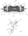
- an inline transducer meter assembly 100 is illustrated in accordance with an embodiment.
- the inline transducer meter assembly 100 can also be referred to generally in industry and within this description as a "flow tube assembly".
- the inline transducer meter assembly 100 includes an inline transducer meter body 110 with an inlet 111 where fluid can flow into the inline transducer meter assembly 100 and an outlet 112 where fluid can flow out of the inline transducer meter assembly 100.
- the inline transducer meter assembly 100 can be adapted to hold at least one transducer 121 between the inlet 111 and the outlet 112 and in-line with fluid flowing through an inline transducer meter body 110.
- FIG. 1 illustrates two transducers 121/121' mounted into the inline transducer meter body 110 between the inlet 111 and the outlet 112.
- the two transducers 121/121' shown in FIG. 1 can be, for example, two ultrasonic transducers facing each other within the inline transducer meter body 110.
- the configuration illustrated I FIG. 1 is not meant to limit the scope of the embodiments.
- the first transducer assembly 121 located near the inlet 111 can include a circular head section 123 having a circular ledge 127 adapted to interface in a complimentary manner with circular shelf 116 integrated in a flow tube.
- a square or rectangular alignment section 126 can be provided on the first transducer assembly 121 that extends from the circular head section 123 past the circular shelf 116 and can be formed and adapted to interface in a complimentary manner with a square or rectangular portal 117 formed between the circular shelf 116 and an inner surface 115 forming an interior of the inline transducer meter body 110.
- the square or rectangular alignment section 126 can have a reduced surface area to reduce upshot force on the square or rectangular alignment section 126 by fluid flowing through the inline transducer meter body 110 and past the square or rectangular portal 117.
- a transducer holding area 122 can be provided that extends from the square or rectangular alignment section 126 into a center inner area of the inline transducer meter body 110 wherein fluid flows through the inline transducer meter body 110.
- the transducer holder 122 can be adapted to retain a first transducer therein while in alignment within the inline transducer meter body 110 with a second transducer located in a transducer holder of a second transducer assembly 121' held within the inline transducer meter body 110 downline from the first transducer assembly 121 near the outlet 112.
- the first transducer holder 122 can be formed in a fluid flow enhancing profile and configured to retain a flow conditioner 131 in front of the fluid flowing through the inline transducer meter body 110.
- a fluid flow enhancing profile can also be accomplished by utilizing a first narrow support 128 formed between the first transducer holder 122 and the square or rectangular alignment section 126, and a second narrow support 129 formed between the first transducer holder 122 and a positioner formed on and extending from the narrow support 129 opposite the first transducer holder, wherein the positioner 124 can interface with a notch 113 that can be formed in the inner surface 115 of the inline transducer meter body 110 opposite the square or rectangular portal 117.
- the notch 113 can function as a location feature for the positioner 124.
- the positioner 124 can be further configured with its placement in the notch 113 to secure the first transducer assembly 121 and any transducer held within the first transducer holder 122 in alignment with fluid flowing through the inline transducer meter body 110.
- a second transducer assembly 121' located downline from the first transducer assembly 121 near the outlet 112 can also include a circular head section 123' having a circular ledge 127, a transducer holding area 122 that extends from a square or rectangular alignment section 126, a fluid flow enhancing profile with a transducer holding area 122 that can be configured to retain a flow conditioner 131', but behind fluid flowing through the inline transducer meter body 110.
- the fluid flow enhancing profile for the second transducer assembly 121' can also be accomplished by utilizing a first narrow support 128 formed between the transducer holder 122 and the square or rectangular alignment section 126 formed and adapted to interface with a square or rectangular portal 117' formed between circular shelf 116' and an inner surface 115, and a second narrow support 129 formed between the first transducer holder 122 and a positioner 124' formed on and extending from the narrow support 129 opposite the transducer holder 122, wherein positioner 124' can interface with a second notch 113' formed in the inner surface 115 of the inline transducer meter body 110 opposite a second square or rectangular portal 117'.
- positioner 124' can be configured given its secured interface with the notch 113' to further secure the second transducer assembly 121' and any transducer held within the first transducer holder 122 in alignment with fluid flowing through the inline transducer housing assembly body 110 near the outlet 112.
- the circular ledge 127 of the second transducer assembly 121' will be adapted to interface in a complimentary manner with circular shelf 116' integrated in the inline transducer meter body 110.
- a square or rectangular alignment section 126 can be provided on the second transducer assembly 121' that extends from the circular head section 123 past circular shelf 116' and can be formed and adapted to interface a complimentary manner with square or rectangular portal 117' formed between the circular shelf 116' and the inner surface 115 forming an interior of the inline transducer meter body 110.
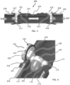
- an inline transducer housing assembly 200 is illustrated in accordance with another embodiment.
- the inline transducer housing assembly 200 shown here can also be referred to generally in industry as a "flow tube".
- the inline transducer meter assembly 200 can also include an inline transducer meter body 210 with an inlet 211 where fluid can flow into the inline transducer meter assembly 200 and an outlet 212 where fluid can flow out of the inline transducer meter assembly 200.
- the inline transducer meter assembly 200 can also be adapted to hold at least one transducer 121/121' between the inlet 211 and the outlet 212 and in-line with fluid flowing through an inline transducer meter body 210.
- the inline transducer meter assembly 200 can also have at least one circular shelf 116, at least one square or rectangular portal 117, and at least one notch 113 formed in the inline transducer meter body 210 of the inline transducer meter assembly 200.
- locking interfaces 217 and 218 can be formed with the inline transducer meter body 210 to connect the inline transducer meter assembly 200 with conduit 219/220 so that fluid if flowing through and into the inline transducer housing assembly 200 can be effectively spliced into the conduit for metering purposes.
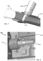
- FIG. 4 illustrated is a close up perspective of a transducer 121 mounted in an inline transducer meter body 210.
- a rubber seal 150 in the form of an O-ring is shown mounted onto the circular ledge 127 of the circular head section 123.
- the rubber seal 150 can be used to create a tight seal between the circular ledge 127 where it can interface in a complimentary manner with circular shelf 216 formed on the inline transducer meter body 210.
- the conditioner 131 is also shown with fluid-flow enhancing arms 132/133 that can cover the first and second narrow supports 128/129 of the transducer holder 122.
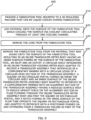
- a fabrication tool 300 that can be utilized to fabricate the inline transducer meter body 110 for the inline transducer meter assembly 100, hereinbefore described, that is formed using 3D printing techniques.
- the fabrication tool 300 can be utilized to 3D fabricate the inline transducer meter body 110.
- Additive manufacturing eliminates various design limitations imposed by existing production methods. Highly complex components that could not be produced in the past are now possible using additive manufacturing.
- the inline transducer meter body 110 can be formed on the surface of the fabrication tool 300, which can be made of metal.
- cooling channels 431/432 to introduce a fluid coolant into the tool to keep its surface cool as material is formed on the outer surface of the tool using additive manufacturing techniques, which are known to produce heat.
- Fluid can be introduced into channel 431 where it moves through coiled tubing 430/330, and then the fluid can be returned (i.e., exit from) channel 432. Fluid can flow continuously through the coiled tubing 430/330 during fabrication of the inline transducer assembly body 110.
- Cooled cores represented by fabrication tool 300 allow for the use of complex cooling channels, which help achieve dimensional stability and straightness for parts, such as the inline transducer meter body 110, during manufacturing.
- the fabrication tool 300 can be provided in two sections 310/410, which can be connected together 370 during processing of the inline transducer meter body 110.
- section 310 can be separated from section 410. What remains after section 310 and 410 are separated is the central core of a fabricated inline transducer meter body 110 as illustrated in FIGS 1 and 3 .
- the fabrication tool can include a channel 320/420 wherein a core 325 can be slid into the channel 320/420.
- the core 325 an prevent material from being placed/deposited where the core 325 is situated within the fabrication tool 300 during moulding/processing.
- FIG. 8 illustrated is an exemplary block diagram of components of an injection mould tool 500 including a core 325 and moving section 310 securely mounted for part moulding.
- Section 310 can be held within block 520 by brass threaded ends 219/220, while core 325 is inserted into section 310. Material can then flow over Section 310 to form the inline transducer meter body.
- a fabrication tool can be provided that can be mounted to a 3D moulding machine and liquid-cooled during fabrication.
- the fabrication tool can have moving sections created by a 3D printer and can include at least one cooling channel therein for accepting fluid coolant to keep the surface cool during fabrication of the inline transducer meter body.
- the fabrication tool can have at least one channel formed through the surface that is configured to receive a square or rectangular core therein to prevent material from being placed in the channel during fabrication.
- material can be added onto the surface of the fabrication tool while cooling the surface via coolant circulating through the at least one cooling channel.
- the core can be removed from the fabrication tool.
- the fabrication tool can be removed from the material that was added onto the surface of the fabrication tool resulting in an inline transducer meter body having an inner surface formed by the surface of the fabrication tool, an inlet and an outlet, a circular shelf integrated in an inline transducer meter body adapted to receive a transducer assembly that interfaces in a complimentary manner with a circular ledge of a circular head section of the transducer assembly, a square or rectangular portal formed between the circular shelf and an inner surface of the inline transducer meter body adapted to interface in a complimentary manner with an alignment section of the transducer assembly having a reduced surface area to reduce upshot force on the alignment section by fluid flowing through the inline transducer meter body and past the square or rectangular portal, and a notch formed in the inner surface of the
- the transducer holder can be positioned near a center of the inline transducer meter body between the square or rectangular portal and the notch.
- the positioner can be further configured to operate with the square or rectangular portal to secure the transducer holder in alignment with the fluid as it flows through the inline transducer meter body.
- Coolant fluid can be introduced into a first channel where it moves through coiled tubing within the fabrication tool and then the coolant fluid is returned from the fabrication tool from a second channel. Coolant fluid can flow continuously through the coiled tubing during fabrication of the inline transducer assembly body.
- the fabrication tool can also include a tapered surface. Two fabrication tools can be connected together to create a tapered inlet and a tapered outlet within the inline transducer assembly body. The two fabrication tools can then be separated after fabrication leaving an inline transducer assembly body that includes a tapered inlet and tapered outlet.
Landscapes
- Physics & Mathematics (AREA)
- Fluid Mechanics (AREA)
- General Physics & Mathematics (AREA)
- Electromagnetism (AREA)
- Measuring Volume Flow (AREA)
- Measurement Of Velocity Or Position Using Acoustic Or Ultrasonic Waves (AREA)
- Measuring Fluid Pressure (AREA)
Claims (10)
- Inline-Wandlermessanordnung (100) mit einem Zufluss (111) und einem Abfluss (112) für Flüssigkeit, die von dem Zufluss zu dem Abfluss durch die Inline-Wandlermessanordnung fließt, wobei die Inline-Wandlermessanordnung Folgendes umfasst:einen runden Einschub (116'), der in einen Inline-Wandlermesskörper (110) integriert ist und zur Aufnahme einer Wandleranordnung (121, 121') geeignet ist, und der auf komplementäre Art und Weise an eine runde Leiste (127) eines runden Kopfteils (123) der Wandleranordnung anschließt;ein quadratisches oder rechteckiges Portal (117), das zwischen dem runden Einschub und einer Innenfläche (115) des Inline-Wandlermesskörpers ausgebildet ist und geeignet ist, um auf komplementäre Art und Weise an ein Ausrichtungsteil der Wandleranordnung anzuschließen, das eine verringerte Fläche hat, um die Endkraft auf das Ausrichtungsteil durch den Durchfluss von Flüssigkeit durch den Inline-Wandlergehäuseanordnungskörper und an dem quadratischen oder rechteckigen Portal vorbei zu verringern; undeine Kerbe (113), die in der Innenfläche der Flussröhre gegenüber dem quadratischen oder rechteckigen Portal ausgebildet ist und geeignet ist, um an einen Positionierer (124) anzuschließen, der als Bestandteil der Wandleranordnung an einem Wandlerhalter (122) ausgebildet ist und sich von ihm erstreckt, wobei der Wandlerhalter nahe der Mitte des Inline-Wandlermesskörpers zwischen dem quadratischen oder rechteckigen Portal und der Kerbe angeordnet ist, wobei der Positionierer weiter dazu konfiguriert ist, mit dem quadratischen oder rechteckigen Portal zu interagieren, um den Wandlerhalter in Ausrichtung mit der Flüssigkeit fixieren, wenn diese durch den Inline-Wandlermesskörper fließt.
- Inline-Wandlermessanordnung nach Anspruch 1, wobei die Wandlerhalter der Wandleranordnung und der zweiten Wandleranordnung ein piezoelektrisches Element darin und in Kommunikation miteinander umfassen.
- Inline-Wandlermessanordnung nach Anspruch 2, wobei das piezoelektrische Element durch ein Kabel verbunden ist, das von dem runden Kopfteil aus zugänglich ist.
- Inline-Wandlermessanordnung nach Anspruch 1, ferner umfassend zumindest einen Strömungsgleichrichter (131, 131'), der mit einer Oberfläche zumindest eines der Wandlerhalter gekoppelt ist, um den Fluss der Flüssigkeit, die durch den Inline-Wandlermesskörper fließt, zu verbessern.
- Inline-Wandlermessanordnung nach Anspruch 1, ferner umfassend:einen zweiten runden Einschub (116'), der in den Inline-Wandlermesskörper zwischen dem runden Einschub und dem Abfluss integriert ist, wobei der zweite runde Einschub zur Aufnahme einer zweiten Wandleranordnung (121') geeignet ist und auf komplementäre Art und Weise an die runde Leiste des runden Kopfteils der zweiten Wandleranordnung anschließt;ein zweites quadratisches oder rechteckiges Portal (117'), das zwischen dem zweiten runden Einschub und der Innenfläche des Inline-Wandlermesskörpers ausgebildet ist, wobei das zweite quadratische oder rechteckige Portal geeignet ist, um auf komplementäre Art und Weise an ein Ausrichtungsteil der zweiten Wandleranordnung anzuschließen, das eine verringerte Fläche hat, um die Endkraft auf das Ausrichtungsteil durch den Durchfluss von Flüssigkeit durch den Inline-Wandlermesskörper und an dem zweiten quadratischen oder rechteckigen Portal vorbei zu verringern; undeine zweite Kerbe (113'), die in der Innenfläche des Inline-Wandlermesskörpers gegenüber dem zweiten quadratischen oder rechteckigen Portal ausgebildet ist und geeignet ist, um an einen Positionierer (124") anzuschließen, der als Bestandteil der zweiten Wandleranordnung (122') an einem Wandlerhalter (122') ausgebildet ist und sich von ihm erstreckt, wobei der Wandlerhalter nahe der Mitte des Inline-Wandlermesskörpers zwischen dem zweiten quadratischen oder rechteckigen Portal und der zweiten Kerbe angeordnet ist, wobei der Positionierer weiter dazu konfiguriert ist, mit dem zweiten quadratischen oder rechteckigen Portal zu interagieren, um den Wandlerhalter in Ausrichtung mit der Flüssigkeit festzustellen, die durch den Inline-Wandlermesskörper fließt.
- Inline-Wandlermessanordnung nach Anspruch 5, wobei die Wandleranordnung mit ihrem Wandlerhalter in dem Inline-Wandlermesskörper nahe dem Zufluss angeordnet ist und wobei die zweite Wandleranordnung nahe dem Abfluss mit ihrem Wandlerhalter im Inline-Wandlermesskörper und in Ausrichtung mit dem Wandlerhalter der Wandleranordnung angeordnet ist.
- Inline-Wandlermessanordnung nach Anspruch 5, wobei die Wandlerhalter der Wandleranordnung und der zweiten Wandleranordnung ein piezoelektrisches Element darin und in Kommunikation miteinander umfassen.
- Inline-Wandlermessanordnung nach Anspruch 1, umfassend:das runde Kopfteil mit der runden Leiste, die geeignet ist, um mit einem runden, in der Flussröhre integrierten Einschub abzuschließen;ein quadratisches oder rechteckiges Ausrichtungsteil, das sich von dem runden Kopfteil innerhalb des runden Einschubs erstreckt und geeignet ist, um an das quadratische oder rechteckige Portal anzuschließen, das zwischen dem Einschub und einer Innenfläche der Flussröhre ausgebildet ist, wobei das quadratische oder rechteckige Ausrichtungsteil eine verringerte Fläche hat, um die Endkraft auf das quadratische oder rechteckige Ausrichtungsteil durch den Durchfluss von Flüssigkeit durch die Flussröhre zu verringern; undden Wandlerhalter, der sich von dem quadratischen oder rechteckigen Ausrichtungsteil in einen Innenbereich der Flussröhre erstreckt, in dem Flüssigkeit durch die Flussröhre fließt, wobei der Wandlerhalter geeignet ist, um einen ersten Wandler in Ausrichtung mit einem zweiten, innerhalb der Flussröhre unterhalb des Wandlers angeordneten Wandler zu halten, wobei der Wandlerhalter in einem den Fluss der Flüssigkeit verbessernden Profil ausgebildet ist und dazu konfiguriert ist, einen Strömungsgleichrichter vor der durch die Flussröhre fließenden Flüssigkeit zu halten.
- Inline-Wandlermessanordnung nach Anspruch 8, ferner umfassend:einen zweiten runden Einschub, der in den Inline-Wandlermesskörper zwischen dem runden Einschub und dem Abfluss integriert ist, wobei der zweite runde Einschub zur Aufnahme einer zweiten Wandleranordnung geeignet ist und auf komplementäre Art und Weise an eine runde Leiste eines runden Kopfteils der zweiten Wandleranordnung anschließt;ein zweites quadratisches oder rechteckiges Portal, das zwischen dem zweiten runden Einschub und der Innenfläche des Inline-Wandlermesskörpers ausgebildet ist, wobei das zweite quadratische oder rechteckige Portal geeignet ist, um auf komplementäre Art und Weise an ein Ausrichtungsteil der zweiten Wandleranordnung anzuschließen, das eine verringerte Fläche hat, um die Endkraft auf das Ausrichtungsteil durch den Durchfluss von Flüssigkeit durch den Inline-Wandlermesskörper und an dem zweiten quadratischen oder rechteckigen Portal vorbei zu verringern; undeine zweite Kerbe, die in der Innenfläche des Inline-Wandlermesskörpers gegenüber dem zweiten quadratischen oder rechteckigen Portal ausgebildet ist und geeignet ist, um an einen Positionierer anzuschließen, der als Bestandteil der zweiten Wandleranordnung an einem Wandlerhalter ausgebildet ist und sich von ihm erstreckt, wobei der Wandlerhalter nahe der Mitte des Inline-Wandlermesskörpers zwischen dem zweiten quadratischen oder rechteckigen Portal und der zweiten Kerbe angeordnet ist, wobei der Positionierer weiter dazu konfiguriert ist, mit dem zweiten quadratischen oder rechteckigen Portal zu interagieren, um den Wandlerhalter in Ausrichtung mit der Flüssigkeit zu fixieren, die durch den Inline-Wandlermesskörper fließt.
- Verfahren zum Herstellen eines Inline-Wandlermesskörpers mit 3D-Guss, umfassend die folgenden Schritte:Bereitstellen eines Herstellungswerkzeugs, das an einer 3D-Gießmaschine montiert werden kann, wobei das Herstellungswerkzeug ein durch einen 3D-Drucker gebildetes Bewegungsteil hat und zumindest einen Kühlungskanal darin umfasst, zum Aufnehmen von flüssigem Kühlmittel, um die Oberfläche während der Herstellung des Inline-Wandlermesskörpers kühl zu halten, wobei das Herstellungswerkzeug zumindest einen Kanal hat, der durch die Oberfläche ausgebildet ist, die dazu konfiguriert ist, einen quadratischen oder rechteckigen Kern darin aufzunehmen, um zu verhindern, dass während der Herstellung Material in den Kanal eingebracht wird;Hinzufügen von Material auf die Oberfläche unter Verwendung von Gießen unter gleichzeitiger Kühlung der Oberfläche über ein Kühlmittel, das durch den zumindest einen Werkzeugkanal zirkuliert;Entfernen des Kerns aus dem Herstellungswerkzeug; undEntfernen des Herstellungswerkzeugs von dem auf der Oberfläche des Herstellungswerkzeugs hinzugefügten Material;wobei das Entfernen des Kerns aus dem Herstellungswerkzeug und dann das Entfernen des Herstellungswerkzeugs von dem Material einen Inline-Wandlermesskörper ergibt, der Folgendes hat: eine durch die Oberfläche des Herstellungswerkzeugs ausgebildete Innenfläche; einen Zufluss und einen Abfluss; einen runden Einschub, der in einen Inline-Wandlermesskörper integriert ist und zur Aufnahme einer Wandleranordnung geeignet ist, und der auf komplementäre Art und Weise an eine runde Leiste eines runden Kopfteils der Wandleranordnung anschließt; ein quadratisches oder rechteckiges Portal, das zwischen dem runden Einschub und einer Innenfläche des Inline-Wandlermesskörpers ausgebildet ist, das geeignet ist, um auf komplementäre Art und Weise an ein Ausrichtungsteil der Wandleranordnung anzuschließen, das eine verringerte Fläche hat, um die Endkraft auf das Ausrichtungsteil durch den Durchfluss von Flüssigkeit durch den Inline-Wandlermesskörper und an dem zweiten quadratischen oder rechteckigen Portal vorbei zu verringern; und eine Kerbe, die in der Innenfläche der Flussröhre gegenüber dem quadratischen oder rechteckigen Portal ausgebildet ist und geeignet ist, um an einen Positionierer anzuschließen, der als Bestandteil der Wandleranordnung an einem Wandlerhalter ausgebildet ist und sich von ihm erstreckt, wobei der Wandlerhalter nahe der Mitte des Inline-Wandlermesskörpers zwischen dem quadratischen oder rechteckigen Portal und der Kerbe angeordnet ist, wobei der Positionierer weiter dazu konfiguriert ist, mit dem quadratischen oder rechteckigen Portal zu interagieren, um den Wandlerhalter in Ausrichtung mit der Flüssigkeit festzustellen, wenn diese durch den Inline-Wandlermesskörper fließt.
Applications Claiming Priority (1)
| Application Number | Priority Date | Filing Date | Title |
|---|---|---|---|
| US17/176,168 US11906337B2 (en) | 2021-02-15 | 2021-02-15 | Inline transducer housing assembly |
Publications (2)
| Publication Number | Publication Date |
|---|---|
| EP4043839A1 EP4043839A1 (de) | 2022-08-17 |
| EP4043839B1 true EP4043839B1 (de) | 2024-07-24 |
Family
ID=80034975
Family Applications (1)
| Application Number | Title | Priority Date | Filing Date |
|---|---|---|---|
| EP22153492.8A Active EP4043839B1 (de) | 2021-02-15 | 2022-01-26 | Inline-wandlergehäuseanordnung |
Country Status (3)
| Country | Link |
|---|---|
| US (1) | US11906337B2 (de) |
| EP (1) | EP4043839B1 (de) |
| AU (1) | AU2022200336B2 (de) |
Family Cites Families (6)
| Publication number | Priority date | Publication date | Assignee | Title |
|---|---|---|---|---|
| JPH10142017A (ja) * | 1996-11-11 | 1998-05-29 | Saginomiya Seisakusho Inc | カルマン渦流量計 |
| CA2617287C (en) * | 1997-06-17 | 2011-11-15 | Fisher & Paykel Healthcare Limited | Respiratory humidification system |
| FR3032524B1 (fr) * | 2015-02-10 | 2017-03-24 | Yzatec | Transducteur ultrasonore, son procede de montage et debitmetre comprenant au moins un tel transducteur |
| FR3035513B1 (fr) * | 2015-04-23 | 2018-09-07 | Integra Metering Sas | Dispositif de mesure de vitesse d'ecoulement d'un fluide a transducteur(s) ultrasonore(s) |
| FR3047068B1 (fr) * | 2016-01-25 | 2019-07-19 | Integra Metering Sas | Dispositif de montage d'un transducteur a ultrasons et debitmetre equipe d'un tel dispositif |
| US10823597B2 (en) * | 2017-12-14 | 2020-11-03 | Arad Ltd. | Ultrasonic water meter including a metallic outer body and polymeric inner lining sleeve |
-
2021
- 2021-02-15 US US17/176,168 patent/US11906337B2/en active Active
-
2022
- 2022-01-19 AU AU2022200336A patent/AU2022200336B2/en active Active
- 2022-01-26 EP EP22153492.8A patent/EP4043839B1/de active Active
Also Published As
| Publication number | Publication date |
|---|---|
| AU2022200336B2 (en) | 2022-12-15 |
| US20220260401A1 (en) | 2022-08-18 |
| AU2022200336A1 (en) | 2022-09-01 |
| US11906337B2 (en) | 2024-02-20 |
| EP4043839A1 (de) | 2022-08-17 |
Similar Documents
| Publication | Publication Date | Title |
|---|---|---|
| US8181534B2 (en) | Ultrasonic flow meter with transducer assembly, and method of manufacturing the same while maintaining the radial position of the piezoelectric element | |
| EP2920556B1 (de) | System und verfahren zur ultraschallmessung mithilfe einer bohrungsmessvorrichtung | |
| US9372106B2 (en) | Non-circular flowmeter | |
| CN211205407U (zh) | 超声波流量计和换能器组件 | |
| EP2893300B1 (de) | Differenzdruck-durchflussmessgerät mit gewinkelten drucköffnungen | |
| JP6408553B2 (ja) | 接着ptfe電極を備えた磁気流量計 | |
| US9297679B2 (en) | Flowmeter with a flow conditioner formed by a protrusion having restriction provided upstream of the measurement section | |
| CN103733031A (zh) | 用于测量和/或监控在管线中流动的介质的参数的传感器模块和用其形成的测量系统 | |
| AU2022200336B2 (en) | Inline transducer housing assembly | |
| JP4455000B2 (ja) | ガスメータ | |
| EP3798582B1 (de) | Ultraschalldurchflussmesser und flüssigkeitsleitung | |
| US11846531B2 (en) | Ultrasonic flow meter with inner and outer flow channels | |
| CN112577557B (zh) | 超声波流量计和流体管路 | |
| JP5434308B2 (ja) | 超音波式流量計測装置 | |
| US20230012765A1 (en) | Method for producing a measurement tube assembly for a coriolis flow meter | |
| CN119836562A (zh) | 用于超声波流量计的结合式封围件 | |
| JP4789435B2 (ja) | 超音波式流量計測装置 | |
| JP4443980B2 (ja) | 流量検出装置 | |
| Monji et al. | Characteristics of Ultrasonic Flowmeter Located Downstream of Elbow | |
| KR20080005041U (ko) | 오리피스를 이용한 유량측정기 |
Legal Events
| Date | Code | Title | Description |
|---|---|---|---|
| PUAI | Public reference made under article 153(3) epc to a published international application that has entered the european phase |
Free format text: ORIGINAL CODE: 0009012 |
|
| STAA | Information on the status of an ep patent application or granted ep patent |
Free format text: STATUS: REQUEST FOR EXAMINATION WAS MADE |
|
| 17P | Request for examination filed |
Effective date: 20220126 |
|
| AK | Designated contracting states |
Kind code of ref document: A1 Designated state(s): AL AT BE BG CH CY CZ DE DK EE ES FI FR GB GR HR HU IE IS IT LI LT LU LV MC MK MT NL NO PL PT RO RS SE SI SK SM TR |
|
| P01 | Opt-out of the competence of the unified patent court (upc) registered |
Effective date: 20230414 |
|
| GRAP | Despatch of communication of intention to grant a patent |
Free format text: ORIGINAL CODE: EPIDOSNIGR1 |
|
| STAA | Information on the status of an ep patent application or granted ep patent |
Free format text: STATUS: GRANT OF PATENT IS INTENDED |
|
| RIC1 | Information provided on ipc code assigned before grant |
Ipc: G01F 15/18 20060101ALI20240220BHEP Ipc: G01D 11/30 20060101ALI20240220BHEP Ipc: G01F 1/66 20220101AFI20240220BHEP |
|
| INTG | Intention to grant announced |
Effective date: 20240311 |
|
| GRAS | Grant fee paid |
Free format text: ORIGINAL CODE: EPIDOSNIGR3 |
|
| GRAA | (expected) grant |
Free format text: ORIGINAL CODE: 0009210 |
|
| STAA | Information on the status of an ep patent application or granted ep patent |
Free format text: STATUS: THE PATENT HAS BEEN GRANTED |
|
| AK | Designated contracting states |
Kind code of ref document: B1 Designated state(s): AL AT BE BG CH CY CZ DE DK EE ES FI FR GB GR HR HU IE IS IT LI LT LU LV MC MK MT NL NO PL PT RO RS SE SI SK SM TR |
|
| REG | Reference to a national code |
Ref country code: GB Ref legal event code: FG4D |
|
| REG | Reference to a national code |
Ref country code: CH Ref legal event code: EP |
|
| REG | Reference to a national code |
Ref country code: IE Ref legal event code: FG4D Ref country code: DE Ref legal event code: R096 Ref document number: 602022004679 Country of ref document: DE |
|
| REG | Reference to a national code |
Ref country code: LT Ref legal event code: MG9D |
|
| REG | Reference to a national code |
Ref country code: NL Ref legal event code: MP Effective date: 20240724 |
|
| PG25 | Lapsed in a contracting state [announced via postgrant information from national office to epo] |
Ref country code: PT Free format text: LAPSE BECAUSE OF FAILURE TO SUBMIT A TRANSLATION OF THE DESCRIPTION OR TO PAY THE FEE WITHIN THE PRESCRIBED TIME-LIMIT Effective date: 20241125 |
|
| REG | Reference to a national code |
Ref country code: AT Ref legal event code: MK05 Ref document number: 1706685 Country of ref document: AT Kind code of ref document: T Effective date: 20240724 |
|
| PG25 | Lapsed in a contracting state [announced via postgrant information from national office to epo] |
Ref country code: NL Free format text: LAPSE BECAUSE OF FAILURE TO SUBMIT A TRANSLATION OF THE DESCRIPTION OR TO PAY THE FEE WITHIN THE PRESCRIBED TIME-LIMIT Effective date: 20240724 |
|
| PG25 | Lapsed in a contracting state [announced via postgrant information from national office to epo] |
Ref country code: PT Free format text: LAPSE BECAUSE OF FAILURE TO SUBMIT A TRANSLATION OF THE DESCRIPTION OR TO PAY THE FEE WITHIN THE PRESCRIBED TIME-LIMIT Effective date: 20241125 Ref country code: NL Free format text: LAPSE BECAUSE OF FAILURE TO SUBMIT A TRANSLATION OF THE DESCRIPTION OR TO PAY THE FEE WITHIN THE PRESCRIBED TIME-LIMIT Effective date: 20240724 |
|
| PG25 | Lapsed in a contracting state [announced via postgrant information from national office to epo] |
Ref country code: NO Free format text: LAPSE BECAUSE OF FAILURE TO SUBMIT A TRANSLATION OF THE DESCRIPTION OR TO PAY THE FEE WITHIN THE PRESCRIBED TIME-LIMIT Effective date: 20241024 |
|
| PG25 | Lapsed in a contracting state [announced via postgrant information from national office to epo] |
Ref country code: PL Free format text: LAPSE BECAUSE OF FAILURE TO SUBMIT A TRANSLATION OF THE DESCRIPTION OR TO PAY THE FEE WITHIN THE PRESCRIBED TIME-LIMIT Effective date: 20240724 Ref country code: GR Free format text: LAPSE BECAUSE OF FAILURE TO SUBMIT A TRANSLATION OF THE DESCRIPTION OR TO PAY THE FEE WITHIN THE PRESCRIBED TIME-LIMIT Effective date: 20241025 Ref country code: FI Free format text: LAPSE BECAUSE OF FAILURE TO SUBMIT A TRANSLATION OF THE DESCRIPTION OR TO PAY THE FEE WITHIN THE PRESCRIBED TIME-LIMIT Effective date: 20240724 |
|
| PG25 | Lapsed in a contracting state [announced via postgrant information from national office to epo] |
Ref country code: BG Free format text: LAPSE BECAUSE OF FAILURE TO SUBMIT A TRANSLATION OF THE DESCRIPTION OR TO PAY THE FEE WITHIN THE PRESCRIBED TIME-LIMIT Effective date: 20240724 |
|
| PG25 | Lapsed in a contracting state [announced via postgrant information from national office to epo] |
Ref country code: LV Free format text: LAPSE BECAUSE OF FAILURE TO SUBMIT A TRANSLATION OF THE DESCRIPTION OR TO PAY THE FEE WITHIN THE PRESCRIBED TIME-LIMIT Effective date: 20240724 |
|
| PG25 | Lapsed in a contracting state [announced via postgrant information from national office to epo] |
Ref country code: AT Free format text: LAPSE BECAUSE OF FAILURE TO SUBMIT A TRANSLATION OF THE DESCRIPTION OR TO PAY THE FEE WITHIN THE PRESCRIBED TIME-LIMIT Effective date: 20240724 Ref country code: IS Free format text: LAPSE BECAUSE OF FAILURE TO SUBMIT A TRANSLATION OF THE DESCRIPTION OR TO PAY THE FEE WITHIN THE PRESCRIBED TIME-LIMIT Effective date: 20241124 |
|
| PG25 | Lapsed in a contracting state [announced via postgrant information from national office to epo] |
Ref country code: HR Free format text: LAPSE BECAUSE OF FAILURE TO SUBMIT A TRANSLATION OF THE DESCRIPTION OR TO PAY THE FEE WITHIN THE PRESCRIBED TIME-LIMIT Effective date: 20240724 |
|
| PG25 | Lapsed in a contracting state [announced via postgrant information from national office to epo] |
Ref country code: RS Free format text: LAPSE BECAUSE OF FAILURE TO SUBMIT A TRANSLATION OF THE DESCRIPTION OR TO PAY THE FEE WITHIN THE PRESCRIBED TIME-LIMIT Effective date: 20241024 Ref country code: ES Free format text: LAPSE BECAUSE OF FAILURE TO SUBMIT A TRANSLATION OF THE DESCRIPTION OR TO PAY THE FEE WITHIN THE PRESCRIBED TIME-LIMIT Effective date: 20240724 |
|
| PG25 | Lapsed in a contracting state [announced via postgrant information from national office to epo] |
Ref country code: RS Free format text: LAPSE BECAUSE OF FAILURE TO SUBMIT A TRANSLATION OF THE DESCRIPTION OR TO PAY THE FEE WITHIN THE PRESCRIBED TIME-LIMIT Effective date: 20241024 Ref country code: PL Free format text: LAPSE BECAUSE OF FAILURE TO SUBMIT A TRANSLATION OF THE DESCRIPTION OR TO PAY THE FEE WITHIN THE PRESCRIBED TIME-LIMIT Effective date: 20240724 Ref country code: NO Free format text: LAPSE BECAUSE OF FAILURE TO SUBMIT A TRANSLATION OF THE DESCRIPTION OR TO PAY THE FEE WITHIN THE PRESCRIBED TIME-LIMIT Effective date: 20241024 Ref country code: LV Free format text: LAPSE BECAUSE OF FAILURE TO SUBMIT A TRANSLATION OF THE DESCRIPTION OR TO PAY THE FEE WITHIN THE PRESCRIBED TIME-LIMIT Effective date: 20240724 Ref country code: IS Free format text: LAPSE BECAUSE OF FAILURE TO SUBMIT A TRANSLATION OF THE DESCRIPTION OR TO PAY THE FEE WITHIN THE PRESCRIBED TIME-LIMIT Effective date: 20241124 Ref country code: HR Free format text: LAPSE BECAUSE OF FAILURE TO SUBMIT A TRANSLATION OF THE DESCRIPTION OR TO PAY THE FEE WITHIN THE PRESCRIBED TIME-LIMIT Effective date: 20240724 Ref country code: GR Free format text: LAPSE BECAUSE OF FAILURE TO SUBMIT A TRANSLATION OF THE DESCRIPTION OR TO PAY THE FEE WITHIN THE PRESCRIBED TIME-LIMIT Effective date: 20241025 Ref country code: FI Free format text: LAPSE BECAUSE OF FAILURE TO SUBMIT A TRANSLATION OF THE DESCRIPTION OR TO PAY THE FEE WITHIN THE PRESCRIBED TIME-LIMIT Effective date: 20240724 Ref country code: ES Free format text: LAPSE BECAUSE OF FAILURE TO SUBMIT A TRANSLATION OF THE DESCRIPTION OR TO PAY THE FEE WITHIN THE PRESCRIBED TIME-LIMIT Effective date: 20240724 Ref country code: BG Free format text: LAPSE BECAUSE OF FAILURE TO SUBMIT A TRANSLATION OF THE DESCRIPTION OR TO PAY THE FEE WITHIN THE PRESCRIBED TIME-LIMIT Effective date: 20240724 Ref country code: AT Free format text: LAPSE BECAUSE OF FAILURE TO SUBMIT A TRANSLATION OF THE DESCRIPTION OR TO PAY THE FEE WITHIN THE PRESCRIBED TIME-LIMIT Effective date: 20240724 |
|
| PG25 | Lapsed in a contracting state [announced via postgrant information from national office to epo] |
Ref country code: RO Free format text: LAPSE BECAUSE OF FAILURE TO SUBMIT A TRANSLATION OF THE DESCRIPTION OR TO PAY THE FEE WITHIN THE PRESCRIBED TIME-LIMIT Effective date: 20240724 Ref country code: DK Free format text: LAPSE BECAUSE OF FAILURE TO SUBMIT A TRANSLATION OF THE DESCRIPTION OR TO PAY THE FEE WITHIN THE PRESCRIBED TIME-LIMIT Effective date: 20240724 Ref country code: SM Free format text: LAPSE BECAUSE OF FAILURE TO SUBMIT A TRANSLATION OF THE DESCRIPTION OR TO PAY THE FEE WITHIN THE PRESCRIBED TIME-LIMIT Effective date: 20240724 |
|
| PG25 | Lapsed in a contracting state [announced via postgrant information from national office to epo] |
Ref country code: EE Free format text: LAPSE BECAUSE OF FAILURE TO SUBMIT A TRANSLATION OF THE DESCRIPTION OR TO PAY THE FEE WITHIN THE PRESCRIBED TIME-LIMIT Effective date: 20240724 |
|
| PG25 | Lapsed in a contracting state [announced via postgrant information from national office to epo] |
Ref country code: CZ Free format text: LAPSE BECAUSE OF FAILURE TO SUBMIT A TRANSLATION OF THE DESCRIPTION OR TO PAY THE FEE WITHIN THE PRESCRIBED TIME-LIMIT Effective date: 20240724 |
|
| REG | Reference to a national code |
Ref country code: DE Ref legal event code: R097 Ref document number: 602022004679 Country of ref document: DE |
|
| PG25 | Lapsed in a contracting state [announced via postgrant information from national office to epo] |
Ref country code: SK Free format text: LAPSE BECAUSE OF FAILURE TO SUBMIT A TRANSLATION OF THE DESCRIPTION OR TO PAY THE FEE WITHIN THE PRESCRIBED TIME-LIMIT Effective date: 20240724 Ref country code: IT Free format text: LAPSE BECAUSE OF FAILURE TO SUBMIT A TRANSLATION OF THE DESCRIPTION OR TO PAY THE FEE WITHIN THE PRESCRIBED TIME-LIMIT Effective date: 20240724 |
|
| PLBE | No opposition filed within time limit |
Free format text: ORIGINAL CODE: 0009261 |
|
| STAA | Information on the status of an ep patent application or granted ep patent |
Free format text: STATUS: NO OPPOSITION FILED WITHIN TIME LIMIT |
|
| 26N | No opposition filed |
Effective date: 20250425 |
|
| REG | Reference to a national code |
Ref country code: DE Ref legal event code: R119 Ref document number: 602022004679 Country of ref document: DE |
|
| REG | Reference to a national code |
Ref country code: CH Ref legal event code: PL |
|
| PG25 | Lapsed in a contracting state [announced via postgrant information from national office to epo] |
Ref country code: SE Free format text: LAPSE BECAUSE OF FAILURE TO SUBMIT A TRANSLATION OF THE DESCRIPTION OR TO PAY THE FEE WITHIN THE PRESCRIBED TIME-LIMIT Effective date: 20240724 |
|
| PG25 | Lapsed in a contracting state [announced via postgrant information from national office to epo] |
Ref country code: LU Free format text: LAPSE BECAUSE OF NON-PAYMENT OF DUE FEES Effective date: 20250126 Ref country code: MC Free format text: LAPSE BECAUSE OF FAILURE TO SUBMIT A TRANSLATION OF THE DESCRIPTION OR TO PAY THE FEE WITHIN THE PRESCRIBED TIME-LIMIT Effective date: 20240724 |
|
| PG25 | Lapsed in a contracting state [announced via postgrant information from national office to epo] |
Ref country code: DE Free format text: LAPSE BECAUSE OF NON-PAYMENT OF DUE FEES Effective date: 20250801 |
|
| PG25 | Lapsed in a contracting state [announced via postgrant information from national office to epo] |
Ref country code: BE Free format text: LAPSE BECAUSE OF NON-PAYMENT OF DUE FEES Effective date: 20250131 |
|
| PG25 | Lapsed in a contracting state [announced via postgrant information from national office to epo] |
Ref country code: FR Free format text: LAPSE BECAUSE OF NON-PAYMENT OF DUE FEES Effective date: 20250131 |
|
| PG25 | Lapsed in a contracting state [announced via postgrant information from national office to epo] |
Ref country code: CH Free format text: LAPSE BECAUSE OF NON-PAYMENT OF DUE FEES Effective date: 20250131 |
|
| REG | Reference to a national code |
Ref country code: BE Ref legal event code: MM Effective date: 20250131 |
|
| PG25 | Lapsed in a contracting state [announced via postgrant information from national office to epo] |
Ref country code: IE Free format text: LAPSE BECAUSE OF NON-PAYMENT OF DUE FEES Effective date: 20250126 |