EP4043672B1 - Becken und kurbadheizsystem - Google Patents
Becken und kurbadheizsystem Download PDFInfo
- Publication number
- EP4043672B1 EP4043672B1 EP22156091.5A EP22156091A EP4043672B1 EP 4043672 B1 EP4043672 B1 EP 4043672B1 EP 22156091 A EP22156091 A EP 22156091A EP 4043672 B1 EP4043672 B1 EP 4043672B1
- Authority
- EP
- European Patent Office
- Prior art keywords
- heater
- valve
- inflow port
- controller
- water
- Prior art date
- Legal status (The legal status is an assumption and is not a legal conclusion. Google has not performed a legal analysis and makes no representation as to the accuracy of the status listed.)
- Active
Links
Images








Classifications
-
- E—FIXED CONSTRUCTIONS
- E04—BUILDING
- E04H—BUILDINGS OR LIKE STRUCTURES FOR PARTICULAR PURPOSES; SWIMMING OR SPLASH BATHS OR POOLS; MASTS; FENCING; TENTS OR CANOPIES, IN GENERAL
- E04H4/00—Swimming or splash baths or pools
- E04H4/12—Devices or arrangements for circulating water, i.e. devices for removal of polluted water, cleaning baths or for water treatment
- E04H4/129—Systems for heating the water content of swimming pools
-
- F—MECHANICAL ENGINEERING; LIGHTING; HEATING; WEAPONS; BLASTING
- F24—HEATING; RANGES; VENTILATING
- F24H—FLUID HEATERS, e.g. WATER OR AIR HEATERS, HAVING HEAT-GENERATING MEANS, e.g. HEAT PUMPS, IN GENERAL
- F24H1/00—Water heaters, e.g. boilers, continuous-flow heaters or water-storage heaters
- F24H1/10—Continuous-flow heaters, i.e. heaters in which heat is generated only while the water is flowing, e.g. with direct contact of the water with the heating medium
- F24H1/107—Continuous-flow heaters, i.e. heaters in which heat is generated only while the water is flowing, e.g. with direct contact of the water with the heating medium using fluid fuel
-
- F—MECHANICAL ENGINEERING; LIGHTING; HEATING; WEAPONS; BLASTING
- F24—HEATING; RANGES; VENTILATING
- F24H—FLUID HEATERS, e.g. WATER OR AIR HEATERS, HAVING HEAT-GENERATING MEANS, e.g. HEAT PUMPS, IN GENERAL
- F24H1/00—Water heaters, e.g. boilers, continuous-flow heaters or water-storage heaters
- F24H1/54—Water heaters for bathtubs or pools; Water heaters for reheating the water in bathtubs or pools
-
- F—MECHANICAL ENGINEERING; LIGHTING; HEATING; WEAPONS; BLASTING
- F24—HEATING; RANGES; VENTILATING
- F24H—FLUID HEATERS, e.g. WATER OR AIR HEATERS, HAVING HEAT-GENERATING MEANS, e.g. HEAT PUMPS, IN GENERAL
- F24H15/00—Control of fluid heaters
- F24H15/40—Control of fluid heaters characterised by the type of controllers
- F24H15/414—Control of fluid heaters characterised by the type of controllers using electronic processing, e.g. computer-based
- F24H15/45—Control of fluid heaters characterised by the type of controllers using electronic processing, e.g. computer-based remotely accessible
- F24H15/464—Control of fluid heaters characterised by the type of controllers using electronic processing, e.g. computer-based remotely accessible using local wireless communication
-
- F—MECHANICAL ENGINEERING; LIGHTING; HEATING; WEAPONS; BLASTING
- F24—HEATING; RANGES; VENTILATING
- F24H—FLUID HEATERS, e.g. WATER OR AIR HEATERS, HAVING HEAT-GENERATING MEANS, e.g. HEAT PUMPS, IN GENERAL
- F24H9/00—Details
- F24H9/12—Arrangements for connecting heaters to circulation pipes
- F24H9/13—Arrangements for connecting heaters to circulation pipes for water heaters
- F24H9/139—Continuous flow heaters
-
- G—PHYSICS
- G05—CONTROLLING; REGULATING
- G05B—CONTROL OR REGULATING SYSTEMS IN GENERAL; FUNCTIONAL ELEMENTS OF SUCH SYSTEMS; MONITORING OR TESTING ARRANGEMENTS FOR SUCH SYSTEMS OR ELEMENTS
- G05B15/00—Systems controlled by a computer
- G05B15/02—Systems controlled by a computer electric
-
- G—PHYSICS
- G05—CONTROLLING; REGULATING
- G05D—SYSTEMS FOR CONTROLLING OR REGULATING NON-ELECTRIC VARIABLES
- G05D7/00—Control of flow
- G05D7/06—Control of flow characterised by the use of electric means
- G05D7/0617—Control of flow characterised by the use of electric means specially adapted for fluid materials
- G05D7/0629—Control of flow characterised by the use of electric means specially adapted for fluid materials characterised by the type of regulator means
- G05D7/0635—Control of flow characterised by the use of electric means specially adapted for fluid materials characterised by the type of regulator means by action on throttling means
Definitions
- a manually controlled valve is used in relation to a heater bypass to control a flow rate of water entering into the heater.
- the user needs to manually adjust this valve based on various environmental and/or seasonal factors to ensure efficient operation of the heater.
- This manual adjustment is particularly important in systems where the heater comprises a heat pump and maintaining a maximum coefficient of performance (COP) for the heat pump can result in significant energy cost savings.
- COP coefficient of performance
- Document US 4 279 128 A describes a swimming pool heating system which utilizes a heat pump that is used for heating heat transfer fluid which is circulated through the primary coil of a heat exchanger.
- the pool water is circulated through the secondary coil of the heat exchanger by means of a standard pool pump.
- a system bypass line is connected to the pool outlet line and a diverter valve, which is located in the pool return line, is used to divert a portion of the circulated pool water to the heating system.
- Document US 2013/291948 A1 describes techniques for reducing head loss in certain water-recirculation or other systems.
- a motorized diverter valve may be used to divert water away from a heat exchanger when the exchanger is not in use, and the diverted water may flow through a lower-loss system to the next downstream component of the system.
- Embodiments described herein include a connected heating system comprising a heater having a first inflow port and a first outflow port, a controller that monitors one or more conditions relating to the heater, a heater bypass coupled between the first inflow port and the first outflow port, and a valve that controls flow of water received from a pool into the first inflow port and the heater bypass based on operating state identified by the controller. Responsive to the controller identifying the operating state, the controller is configured to transmit control signals that direct actuation of the valve to achieve the operating state.
- the heater is configured to heat portions of the water from the pool that flow between the first inflow port and the first outflow port when a heating mode is active.
- the heater bypass includes a second inflow port coupled to the first inflow port of the heater and a second outflow port coupled to the first outflow port of the heater.
- the valve is coupled between the second inflow port and the second outflow port.
- the operating state includes a timed sequence of actuations of the valve between a closed state and an opened state. In the closed state, the valve blocks flow of the water from the pool between the second inflow port and the second outflow port, and, in the open state, the valve attenuates flow of the water from the pool into the first inflow port by directing the water received from the pool to flow into both and the first inflow port of the heater and the second inflow port of the heater bypass.
- the operating state includes one of a plurality of actuation states of the valve.
- the plurality of actuation states of the value include a fully closed state, a fully open state, and one or more intermediate states.
- the fully closed state the valve directs the water received from the pool to flow into the heater bypass by blocking flow into the first inflow port.
- the fully open state the valve enables water to flow freely into the first inflow port by blocking flow into the heater bypass.
- the valve attenuates flow of the water from the pool into the first inflow port by directing the water received from the pool to flow into both the heater bypass and the first inflow port.
- the heater includes a gas heater comprising a heater control board, an ignition control module electrically connected to the heater control board, a burner, and a blower motor.
- the heater control board is configured to activate the blower motor and direct the ignition control module to ignite the burner to engage the heating mode.
- the heating system further comprises a water temperature sensor electrically coupled to the controller.
- the one or more conditions relating to the heater include a temperature of the water flowing between the first inflow port and the first outflow port as relayed to the controller by the temperature sensor.
- the heater control board disengages the heating mode, and the controller identifies the operating state as an intermediate state where the valve attenuates flow of the water from the pool into the first inflow port by directing the water received from the pool to flow into both the heater bypass and the first inflow port.
- the heater control board comprises the controller.
- the controller is electrically connected to the heater control board via a wireless medium.
- the controller is electrically connected to the heater control board via an RS485 connection that includes a half-duplex 485 link that operates in a listen only mode such that the heater control board is configured to transmit only when sending of data to the controller is required.
- the heater system further comprises an actuator connected to the valve and electrically coupled to the controller.
- the actuator is configured to actuate the valve into the operating state in response to receiving the control signals from the controller.
- the valve includes a T configuration where one opening of the valve is coupled to the first inflow port by a pipe or conduit that is substantially parallel to the ground and another opening of the valve is coupled to the heater bypass.
- the heater bypass is substantially perpendicular to the ground.
- a check valve is positioned between the first outflow port and a second outflow port of the heater bypass to prevent heated water from flowing back into the heater.
- the heater includes a heat pump comprising a heater control board, an expansion valve, a compressor, a condenser coupled between the expansion valve and the compressor, an evaporator coupled between the expansion valve and the compressor, a fan that removes cool air from the heater and directs outside air onto the evaporator, and a thermal fluid configured to circulate through the expansion valve, the compressor, the condenser, and the evaporator.
- the condenser is in contact with the water flowing between the first inflow port and the first outflow port and the heater control board is configured to activate the fan, the expansion valve, and the compressor to circulate the thermal fluid to engage the heating mode.
- the thermal fluid is initially heated by the outside air that collects on the evaporator, is further heated via compression by the compressor, and sheds heat to the water flowing between the first inflow port and the first outflow port at the condenser.
- the connected heating system further comprises a water temperature sensor electrically coupled to the controller and configured to measure and relay to the controller a temperature of the water flowing between the first inflow port and the first outflow port.
- the controller determines that the temperature of the water is below a first preconfigured threshold
- the heater control board engages the heating mode
- the heater control board disengages the heating mode.
- the controller parses the one or more conditions relating to the heater to determine a current coefficient of performance (COP) of the heat pump, and wherein, when the current COP is less than a maximum COP, the controller identifies the operating state for the valve as one where the valve controls the flow of the water received from the pool into the first inflow port and the heater bypass to change the current COP to the maximum COP.
- COP current coefficient of performance
- the connected heating system further comprises a housing that contains the heater control board, the expansion valve, the compressor, the condenser the evaporator, the fan, the valve, and the heater bypass.
- the heater bypass includes a second inflow port coupled to the first inflow port of the heater and a second outflow port coupled to the first outflow port of the heater and the valve is coupled between the second inflow port and the second outflow port.
- the operating state includes a timed sequence of actuations of the valve between a closed state and an opened state. In the closed state, the valve blocks flow of the water from the pool between the second inflow port and the second outflow port.
- the valve In the open state, the valve attenuates flow of the water from the pool into the first inflow port by directing the water received from the pool to flow into both and the first inflow port of the heater and the second inflow port of the heater bypass.
- the controller identifying the operating state so as adjust the current COP to the maximum COP includes the controller identifying a new timed sequence of actuations of the valve between the closed state and the opened state.
- the one or more conditions include at least one or more of a respective temperature of the water at the first inflow port and the first outflow port, a condensing temperature, and pressure at an outlet of the compressor.
- the connected heating system further comprises a plurality of sensors that each correspond to one or more of the one or more conditions monitored by the controller, wherein the plurality of sensor include at least one of a temperature sensor, a pressure sensor, and/or a flow rate monitor.
- the controller is electrically connected to the heater control board via at least one of a wired medium and wireless medium.
- Embodiments described herein also include a connected heating system comprising a heater having a housing, a first inflow port in fluid communication with the housing, a first outflow port, a heater control board disposed inside the housing, an ignition control module electrically connected to the heater control board and disposed inside the housing, a burner disposed inside the housing, and a blower motor disposed inside the housing.
- the connected heating system also comprises a controller that monitors a temperature of water flowing between the inflow port and the outflow port of the heater, a heater bypass coupled between the first inflow port and the first outflow port, and a valve that controls flow of water received from a pool into the first inflow port and the heater bypass based on operating state identified by the controller.
- the controller Responsive to the controller identifying the operating state, the controller is configured to transmit control signals that direct actuation of the valve to achieve the operating state.
- the heater is configured to engage a heating mode to heat portions of the water from the pool that flow between the first inflow port and the first outflow port by activating the blower motor and directing the ignition control module to ignite the burner.
- the operating state includes one of a plurality of actuation states of the valve, the plurality of actuation states of the value including a fully closed state, a fully open state, and one or more intermediate states, wherein, in the fully closed state, the valve directs the water received from the pool to flow into the heater bypass by blocking flow into the first inflow port, wherein, in the fully open state, the valve enables water to flow freely into the first inflow port by blocking flow into the heater bypass, and wherein, in the one or more intermediate states, the valve attenuates flow of the water from the pool into the first inflow port by directing the water received from the pool to flow into both the heater bypass and the first inflow port.
- the connected heating system further comprises a water temperature sensor electrically coupled to the controller.
- the water temperature sensor measures and relays to the controller the temperature of the water flowing between the inflow port and the outflow.
- the controller determines that the temperature of the water is below a first preconfigured threshold, the heater control board engages the heating mode, and the controller identifies the operating state as a fully open state where the valve enables the water from the pool to flow freely into the first inflow port by blocking flow into the heater bypass.
- the heater control board disengages the heating mode, and the controller identifies the operating state as an intermediate state where the valve attenuates flow of the water from the pool into the first inflow port by directing the water received from the pool to flow into both the heater bypass and the first inflow port.
- Embodiments described herein are also directed to a method comprising monitoring a temperature of water flowing between an inflow port and an outflow port of the heater via a controller and a sensor in communication with the controller, engaging a heating mode of the heater to heat the water flowing between the inflow port and the outflow port via a heater control board of the heater when the controller determines that the temperature of the water is below a first preconfigured temperature threshold, sending a first control signal to actuate a valve into a fully open state where the valve enables the water to flow freely into the first inflow port by blocking flow into a heater bypass when the heating mode is engaged, disengaging the heating mode of the heater when the controller determines that the temperature of the water is above a second preconfigured temperature threshold, and sending a second control signal to actuate the valve into an intermediate state where the valve attenuates flow of the water into the inflow port by directing the water to flow into both the heater bypass and the first inflow port when the heating mode is disengaged.
- the first preconfigured temperature is the same as the second preconfigured temperature.
- the controller is electrically connected to the heater control board via an RS485 connection that includes a half-duplex 485 link that operates in a listen only mode such that the heater control board is configured to transmit only when sending of data to the controller is required.
- Embodiments described herein are also directed to a method comprising monitoring one or more conditions relating to a heat pump via a controller, parsing, via the controller, the one or more conditions relating to the heat pump to determine a current coefficient of performance (COP) of the heat pump, identifying, with the controller, an operating state for a valve that adjusts the current COP to the maximum COP when the current COP is less than a maximum COP, transmitting control signals that direct actuation of the valve to achieve the operating state from the controller to an actuator for the valve, actuating the valve into the operating state via the actuator in response to receiving the actuator the control signals from the controller, and controlling flow of water received from a pool into a first inflow port of the heat pump and a second inflow port of heater bypass with the valve to adjust the current COP to the maximum COP when the valve is actuated into the operating state.
- COP current coefficient of performance
- the operating state includes a timed sequence of actuations of the valve between a closed state and an opened state.
- the valve blocks flow of the water from the pool between the second inflow port of the heater bypass and a second outflow port of the heater bypass.
- the valve In the open state, the valve attenuates flow of the water from the pool into the first inflow port by directing the water received from the pool to flow into both and the first inflow port of the heater and the second inflow port of the heater bypass.
- the controller identifying the operating state so as adjust the current COP to the maximum COP includes the controller identifying a new timed sequence of actuations of the valve between the closed state and the opened state.
- the one or more conditions include at least one or more of a respective temperature of the water at the first inflow port of the heat pump and a first outflow port of the heat pump, a condensing temperature, and/or a pressure at an outlet of a compressor of the heat pump.
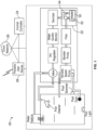
- FIG. 1 illustrates an exemplary connected aquatic application, such as a pool or spa system 20, according to disclosed embodiments.
- the connected pool or spa system 20 can include a heating system 22 configured to heat water for the pool and/or a spa to a set temperature.
- a heating system 22 configured to heat water for the pool and/or a spa to a set temperature.
- One or more additional components may be optionally included in the pool or spa system 20, including, for example, a filter, a booster pump, a variable speed pump, one or more sensors and/or valves, a pH and/or water chemistry regulation mechanism, a water quality monitor, a sanitizer, and various communication enabling devices, described in more detail below.
- One or more of the components are provided in communication with each other and the pool to form a fluid circuit.
- the fluid circuit facilitates water movement from the pool or spa through one or more of the pool components and the fluid circuit to accomplish various tasks including, for example, pumping, cleaning, heating, sanitizing, and the like. Additional arrangements of the one or more additional components besides those shown in FIG.1 that are known in the art are also contemplated.
- the pool or spa system 20 further includes a central controller 24, and a portable user device 26 that can interface with the central controller 24, either directly over a local area network, or via a cloud network 28.
- FIG. 1 depicts the central controller 24, the portable user device 26, and the cloud network 28, it should be noted that various communication methodologies and connections may be implemented to work in conjunction with, or independent from, one or more local controllers associated with each individual components associated with the pool or spa system 20 (e.g., controller of the pump, controller of the heater, etc.).
- the heating system 22 is provided in the form of a heater 30, a heater control board 32, and a valve 34 that is configured to control flow of water into and out of the heater 30.
- the heater 30 includes a housing 31 in fluid communication with a first inflow port 33 and a first outflow port 35 designed to accommodate incoming and outgoing water, respectively, through the heater 30.
- Plumbing is provided to facilitate fluid communication between the various components of the heating system 22.
- the heater bypass 23 can be coupled between the first inflow port 33 and the first outflow port 35 and can include a second inflow port 25 and a second outflow port 27.
- the heating system 22 can include a check valve 36 provided in the plumbing of the first outflow port 35 of the heater 30 that is designed to prevent heated water from flowing back into the heater 30.
- a controller such as the heater control board 32, the central controller 24, and/or the portable user device 26, can monitor one or more conditions relating to the heater 30.
- the valve 34 can be configured to control flow of water received from a pool into the first inflow port 33 and the heater bypass 23 based on operating state identified by the controller, and the heater 30 can be configured to heat portions of the water from the pool that flow between the first inflow port 33 and the first outflow port 35 when a heating mode is active.
- the controller in response to identifying the operating state, can be configured to transmit control signals that direct actuation of the valve 34 to achieve the operating state.
- the controller can be electrically coupled to a plurality of sensors 39 that relay the one or more conditions relating to the heater 30 to the controller.
- the valve 34 can be provided as a three way valve with various open and closed positions, as described hereinbelow.
- the valve 34 can be coupled to the first inflow port 33 of the heater 30 and, in embodiments where the controller comprises the heater control board 32, can be electrically connected to the heater control board 32 to receive control commands therefrom to change a position of the valve 34.
- the valve 34 may be the Intellivalve TM provided by Pentair Water Pool & Spa (Cary, NC). Furthermore, as seen in FIG.
- the valve 34 can be placed outside of the housing 31 and have a T configuration where one opening of the valve 34 is coupled to the first inflow port 33 by a pipe or conduit that is substantially parallel to the ground, and another opening of the valve 34 is coupled to the heater bypass 23 that is substantially perpendicular to the ground.
- the check valve 36 can be positioned between the first outflow port 35 and the second outflow port 27.
- another pipe or conduit between an exit port of the check valve 36 and the second outflow port 27 can have an s-shape configuration where one end is higher of the ground than another end. It should be noted that other additional positions and configurations for the pipes or conduits as known in the art are also contemplated.
- the operating state for the valve 34 can include one of a plurality of actuation states of the valve 34. These plurality of actuation states can include a fully closed state, a fully open state, and one or more intermediate states.
- the fully closed state the valve 34 directs the water received from the pool to flow into the heater bypass 23 by blocking flow into the first inflow port 33.
- the fully open state the valve 34 enables water to flow freely into the first inflow port 33 by blocking flow into the heater bypass 23.
- the valve 34 can attenuate flow of the water from the pool into the first inflow port 33 by directing the water received from the pool to flow into both the heater bypass 23 and the first inflow port 33.
- the heater 30 can include a gas heater that further includes an ignition control board or module 38, a blower motor 40, an exhaust 41, an air/fuel mixing chamber 42, a burner 44, heating coils 46 through which the water fed into the heater 30 flows, and one or more other components associated with a gas heater.
- the ignition control module 38 is coupled to and controlled by the heater control board 32.
- the heater control board 32 is configured to activate the blower motor 40 and direct the ignition control module 38 to ignite the burner 44 to engage the heating mode.
- the heater 30 can have a large internal volume section for accommodating a larger volume of water flow.
- a compact lower internal volume heater is also contemplated.
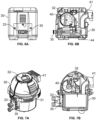
- FIG. 7A and 7B a version of the heater 30 where the housing 31 has a rounded profile is contemplated.
- various orientations for the first inflow port 33 and the first outflow port 35 are contemplated. For example, as seen in FIGS. 5-7B
- the first inflow port 33 and the first outflow port 35 can be arranged in a vertical configuration with the first inflow port 33 on top of the first outflow port 35. Additionally or alternatively, as seen in FIGS. 6A and 6B , the first inflow port 33 and the first outflow port 35 can be arranged in a horizontal configuration where the first inflow port 33 is on a left side of the housing 31 and the first outflow port is on a right side of the housing 31. Additional and alternative arrangements known in the art are also contemplated including arrangements where the positions of the first inflow port 33 and the first outflow port 35 are swapped.
- the controller including but not limited to the heater control board 32, can engage the heating mode and control actuation of the valve 34 based on a temperature of the water flowing between the first inflow port 33 and the first outflow port 35.
- one of the plurality of sensors 39 can include a water temperature sensor (e.g. a thermistor) and the one or more conditions relating to the heater 30 can include the temperature of the water flowing between the first inflow port 33 and the first outflow port 35 as relayed to the controller by the temperature sensor.
- the heater control board 32 when the controller determines that the temperature of the water is below a first preconfigured threshold, the heater control board 32 can engage the heating mode and the controller can identify the operating state for the valve 34 as a fully open state where the valve 34 enables the water from the pool to flow freely into the first inflow port 33 by blocking flow into the heater bypass 23. Furthermore, when the controller determines that the temperature of the water is above a second preconfigured threshold the heater control board 32 can disengage the heating mode and the controller can identify the operating state as an intermediate state where the valve 34 attenuates flow of the water from the pool into the first inflow by directing the water received from the pool to flow into both the heater bypass 23 and the first inflow port 33.
- the first preconfigured threshold can be the same as the second preconfigured threshold. However, in some embodiments the first preconfigured threshold can be lower than the second preconfigured threshold.
- the heater control board 32 is also designed to undertake various other control operations of the heater 30. For example, a user may manually turn the heater 30 on by pushing a button (not shown) on the heater 30, or via an interface provided on the portable user device 26. Alternatively, a user may enter the first or second preconfigured thresholds or other desired water temperature setpoints, or water temperature setpoint ranges (e.g., upper and lower limit) in which the heater 30 should maintain the water temperature at. In other embodiments, the user may set a schedule in which the heater 30 should operate.
- the heater control board 32 may use inputs from one or more of the plurality of sensors 39, internally stored settings, and/or control signals received from other devices (e.g., local on-board controllers, the central controller 24, and/or the portable user device 26) to commence various operations.
- devices e.g., local on-board controllers, the central controller 24, and/or the portable user device 26
- the heater control board 32 is designed to direct (1) the ignition control module 38 to activate the blower motor 40 so as to begin mixing air and fuel together in the mixing chamber 42, and feed the mix of air and fuel to the burner 44, (2) the ignition control module 38 to ignite the burner 44 to combust the mix of air and fuel so that water flowing through the heating coils 46 is heated to the desired temperature, and (3) control operation of the valve 34 to one of the plurality of actuation states where approximately 100% of the water flowing into the valve 34 flows into the heater 30 and through the heating coils 46.
- the one of the plurality of operating states for the valve 34 may be an opened state where a small amount of water (e.g., less than 5%) is bypassed around the heater 30 through the heater bypass 23.
- the heater control board 32 determines that the water has been sufficiently heated and has reached a pre-determined temperature setpoint, the heater control board 32 is designed to direct (1) the ignition control module 38 to deactivate the burner 44 and the blower motor 40, and (2) the valve 34 to transition to a second one of the plurality of operating states where the valve 34 is operated between about 90% to about 95% to allow less than 100% of the water flowing into the valve 34 to flow into the heater 30.
- the valve 34 when in the second one of the plurality of operating, can allow between about 5% to about 10% of the water flowing into the valve 34 to flow into the heater 30.
- Allowing water to flow into the heater 30 when the heater 30 is not actively heating permits measurement of the temperature of the water irrespective of the state of the valve 34. Further, directing a small water flow through the heater 30 during this operation also can reduce the resistance in the system and decrease an amount of wear and tear on a heat exchanger of the heater 30. For example, in some embodiments, when the heater 30 is bypassed, an internal heat exchanger can be exposed to a lower flow rate and a reduced overall volume of water having certain corrosive properties. This can extend the service life of the heat exchanger because the heater 30 can be subjected to a less-corrosive environment during the periods in which the heat exchanger is being bypassed. The bypass operation can also include other benefits.
- a speed of a variable flow pump's motor that pumps water to the heater 30 can be reduced because a total dynamic head of the system will be lower than it is when the heater is not being bypassed. This speed reduction can reduce the electrical usage of the variable speed pump and result in energy bill cost savings for the user.
- the percentages that the valve 34 is opened or closed in the various ones of the plurality of operating states can be set by a user either locally on the heater 30 or via the portable user device 26 through the central controller 24.
- the portable user device 26 can receive user input setting the open/close percentages which the central controller 24 can relay to the heater control board 32 for storage in a local memory thereof.
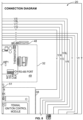
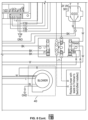
- FIG. 8 is a connection diagram for the heating system 22 according to disclosed embodiments.
- the heater control board 32 can be coupled to various sensors and switches 48 that monitor for and/or activate at the presence of different potential error or fault conditions for the heater 30 and can include a data connection 50 for coupling the heater control board 32 to the valve 34.
- the heater control board 32 can be connected to the central controller 24 using an RS485 connection 49 and can communicate control signals, outputs from the various sensors and switches 48, and other relevant data using a customized protocol.
- the RS485 connection 49 can include a half-duplex 485 link that operates in a listen only mode.
- the listen only mode can include the heater control board 32 being configured to transmit only when sending of data to the central controller 24 is required.
- the heater control board 32 can be configured only to transmit in response to a command from the central controller 24.
- the heater control board 32 can ensure data integrity prior to use of the data, by using one or more of a proper address, a proper opcode, a proper packet length, and a proper checksum when compiling and transmitting data to the central controller 24.
- the central controller 24 can be configured as the system master and also operate in a listen only mode (e.g. transmitting only when required). In these embodiments, the central controller 24 can send continuous 'heartbeat' or 'keep alive' packets to the heater control board 32 at a preconfigured rate, such as, for example, approximately every 2 seconds. The continuous 'heartbeat' or 'keep alive' packets can be sent as an undependable transmission where no response from the heater control board 32 is expected or required. In some embodiments, the heater control board 32 can be configured to revert to a standalone or default operation when the continuous 'heartbeat' or 'keep alive' packets fail to be received for more than a preconfigured amount of time (e.g. 60 seconds).
- a preconfigured amount of time e.g. 60 seconds
- the continuous 'heartbeat' or 'keep alive' packets can be assigned a global destination address when sent to enable the continuous 'heartbeat' or 'keep alive' packets to be received by the heater control board 32 and any other heater control boards in the connected pool or spa system 20.
- the RS485 connection 52 can include color coded 4 wire terminals.
- the 4 wire terminals can be color coded with black indicating a DC/Signal Ground, green indicating RS485 'B' / '-Data', Yellow indicating RS485 'A' / '+Data', and Red indicating +15VDC.
- a command packet from the central controller 24 to the heater control board 32 can include a first preconfigured value associated with the central controller 24 as the source address, a second preconfigured value associated with the heater control board 32 as the destination address, and various control commands for the heater control board 32 in the info field.
- the second preconfigured value can be set via user input on a front panel of the heater 30 and/or remotely via the portable user device 26.
- the various control commands can include one or more of (1) a System On/Off byte configured to switch the heater 30 between a first mode where the heater is deactivated, a second mode where the heater 30 is activated to heat a pool, and/or a third mode where the heater 30 is activated to heat a spa, (2) a Pool Water Heat Set Point byte that sets a specific water temperature (e.g. between 5.6 - 40.0 Celsius ( 42-104 °F) for heating in the second mode, (3) a Spa Water Heat Set Point byte that sets a specific water temperature (e.g. between 5.6 - 40.0 Celsius ( 42-104 °F) for heating in the third mode, and (4) a service mode byte that can switch operation of the heater controller board 32 between remote control, local control, or standalone mode.
- a System On/Off byte configured to switch the heater 30 between a first mode where the heater is deactivated, a second mode where the heater 30 is activated to heat a pool, and/or a third mode where the heater 30 is activate
- a response packet from the heater control board 32 to the central controller 24 can include the second preconfigured value as the source address, the first preconfigured value as the destination address, and operation data about the heater control board 32 in the info field.
- the operation data can include one or more of (1) a heater model ID byte that identifies a model number of the heater 30, (2) a heater mode byte that identifies whether the heater is in the first, second, or third mode, (3) a heating status byte that identifies whether the burner 44 is currently firing or not, and (4) an error mode byte that can include error information pertaining to the potential error or fault conditions for the heater 30 sent as error codes using 8 individual bit flags.
- a value of 0 can be used to indicate NO ERROR.
- spare bytes of the packet can be assigned to additional error codes when more than 8 error codes are needed.
- the various sensors can include one or more of an automatic fuel shutoff switch that stops fuel from flowing into the mixing chamber 42 when a temperature of the water leaving the heater 30 is above a preconfigured threshold (e.g. greater than 60 Celsius ( 140 0 F), a high limit switch that activates when a temperature of the water entering the heater 30 is above a preconfigured threshold (e.g.
- the error codes for the customized protocol can represent different outputs from the various sensors and switches 48.
- the error codes can include (1) an indication that automatic fuel shutoff switch has activated, (2) an indication that the high limit switch has activated, (3) an indication that the pressure switch has activated, (4) an indication that the air flow switch has activated, (4) a thermistor open signal that indicates that thermistor or wiring thereof may be open circuited, (5) a thermistor short signal that indicates that thermistor or wiring thereof may be short circuited, (6) an indication that a value of the SFS has exceeded a preconfigured temperature value (e.g.
- FIG. 9 illustrates another exemplary embodiment of the pool or spa system 20, according to disclosed embodiments.
- the connected pool or spa system 20 can include a heater 52 in place of the heating system 22 that is also configured to heat water for the pool and/or a spa to a set temperature.
- the one or more additional components in the pool or spa system 20, including, for example, the filter, the booster pump, the variable speed pump, the one or more sensors and/or valves, the pH and/or water chemistry regulation mechanism, the water quality monitor, the sanitizer, and the various communication enabling devices, described in more detail below can be arranged in a different configuration from that of FIG. 1 .
- the filter the booster pump
- the variable speed pump the one or more sensors and/or valves
- the pH and/or water chemistry regulation mechanism the water quality monitor, the sanitizer, and the various communication enabling devices, described in more detail below
- the booster pump is positioned after the filter and the water quality monitor is positioned after the filter, before the heater 52, and before the booster pump.
- the one or more additional components in the pool or spa system 20 as would be known to those of ordinary skill in the art are also contemplated.
- the one or more of the components are provided in communication with each other and the pool to form a fluid circuit and/or filtration system.
- the fluid circuit facilitates water movement from the pool or spa through one or more of the pool components and the fluid circuit to accomplish various tasks including, for example, pumping, cleaning, heating, sanitizing, and the like.
- the heater 52 can include a housing 53 in which a heater bypass 58, a condenser 60, a heater control board 56, and a valve 54 are provided.
- the heater 52 includes a first inflow port 62 and a first outflow port 64 from the condenser 60 that are designed to accommodate incoming and outgoing water, respectively, through the condenser 60. Plumbing is provided to facilitate fluid communication between the various components of the heater 52 as would be understood by those having ordinary skill in the art.
- the heater bypass 58 can be coupled between the first inflow port 62 and the first outflow port 64 and can include a second inflow port 66 and a second outflow port 68.
- the second inflow port 66 can be coupled to the first inflow port 62 and the second outflow port 68 can be coupled to the first outflow port 64 inside the housing 53 as seen in FIG. 10 .
- the valve 54 and/or the heater bypass 58 can be provided outside of the housing 53.
- the controller e.g. the heater control board 56, the central controller 24, and/or the portable user device 26
- the controller can monitor one or more conditions relating to the heater 52.
- the valve 54 can be configured to control flow of water received from a pool into the first inflow port 62 and the heater bypass 58 based on operating state identified by the controller, and the heater 52 can be configured to heat portions of the water from the pool that flow between the first inflow port 62 and the first outflow port 64 when a heating mode is active.
- the controller in response to identifying the operating state, can be configured to transmit control signals that direct actuation of the valve 54 to achieve the operating state.
- the controller can be electrically coupled to a plurality of sensors 55 (see FIG. 12 ) that relay the one or more conditions relating to the heater 52 to the controller.
- the valve 54 can be provided as a 2 way valve with various open and closed positions, as described hereinbelow.
- the valve 54 can be coupled between the second inflow port 66 and the second outflow port 68 and, in embodiments where the controller comprises the heater control board 56, can be electrically connected to the heater control board 56 to receive control commands therefrom to change a position of the valve 54.
- the operating state for the valve 54 can include a timed sequence of actuations of the valve 54 between a closed state and an opened state, wherein, in the closed state, the valve blocks flow of the water from the pool between the second inflow port 66 and the second outflow port 68, and wherein, in the open state, the valve attenuates flow of the water from the pool into the first inflow port 62 by directing the water received from the pool to flow into both and the first inflow port 62 and the second inflow port 66.
- the heater 52 can include a heat pump.
- FIG. 11 is a partial cross-sectional view and FIG. 12 is a schematic view of various internal components of a heat pump embodiment of the heater 52 according to disclosed embodiments.
- the heater 52 can include the heater control board 56, an expansion valve 74, a compressor 72, the condenser 60 coupled between the expansion valve 74 and the compressor 72, an evaporator 76 coupled between the expansion valve 74 and the compressor 72, a fan 70 that removes cool air from the heater and directs outside air onto the evaporator 76, and a thermal fluid configured to circulate through the expansion valve 74, the compressor 72, the condenser 60, and the evaporator 76 in a path indicate by arrow A.
- the condenser 60 is in contact with the water flowing between the first inflow port 62 and the first outflow port 64 to transfer heat between the circulating thermal fluid and the water.
- the heater control board 56 can be configured to activate the fan 70, the expansion valve 74, and the compressor 72 to circulate the thermal fluid to engage the heating mode. During such circulation, the thermal fluid is initially heated by the outside air that collects on the evaporator 76, is further heated via compression by the compressor 72, and sheds heat to the water flowing between the first inflow port 62 and the first outflow port 64 at the condenser 60.
- the thermal fluid is heated from a liquid state into a gaseous state before entering the compressor 72 and cooled back into the liquid state when shedding heat to the water flowing between the first inflow port 62 and the first outflow port 64.
- Various embodiments for the thermal fluid are contemplated such as refrigerant fluids like R22, R32, R407, R410, and other similar fluids known in the art.
- the controller can engage the heating mode based on a temperature of the water flowing between the first inflow port 62 and the first outflow port 64.
- one of the plurality of sensors 55 can include a water temperature sensor (e.g. a thermistor) configured to measure and relay to the controller a temperature of the water flowing between the first inflow port 62 and the first outflow port 64.
- the controller determines that the temperature of the water is below a first preconfigured threshold
- the heater control board 56 can engage the heating mode.
- the controller determines that the temperature of the water is above a second preconfigured threshold
- the heater control board 56 can disengage the heating mode.
- the first preconfigured threshold can be the same as the second preconfigured threshold. However, in some embodiments the first preconfigured threshold can be lower than the second preconfigured threshold.
- the controller can control actuation of the valve 54 to mediate flow of water through the condenser 60 such that a COP of the heater 52 is maximized.
- the controller parses the one or more conditions relating to the heater 52 to determine a current COP of the heater 52. When the current COP is less than a maximum COP, the controller identifies the operating state for the valve 54 as one where the valve 54 controls the flow of the water received from the pool into the first inflow port 62 and the heater bypass 58 to change the current COP to the maximum COP.
- the operating state of the valve 54 identified by the controller can include new timed sequence of actuations (e.g. holding the valve 54 open or closed for a longer or shorter time) of the valve 54 between the closed state and the opened state so as adjust the current COP of the heater 52 to the maximum COP.
- the controller can dynamically adjust the timing of the opening and closing of the valve 54 to achieve the maximum COP for the heater 52.
- the controller can continue to adjust the timing of the opening and closing of the valve 54 until the controller determines that the COP for the heater 52 is at the maximum as indicated by the one or more conditions of the heater 52.
- the controller can be configured to wait a preconfigured time after changing the timing of the opening and closing of the valve 54 before continuing to monitor the one or more conditions of the heater 52 and adjusting the timing so as to achieve the maximum COP. Waiting the preconfigured time can enable the one or more conditions of the heater 52 to balance or stabilize in response to the changed timing.
- the one or more conditions monitored by the controller can include at least one of temperature of the water at the first inflow port 62, temperature of the water at the first outflow port 64, a condensing temperature, and pressure of the thermal fluid at an outlet of the compressor 72.
- the one or more conditions monitored by the controller can include environmental conditions, external temperature, seasonal information, geographic information, and/or a flow rate of water through the pool or spa system 20 as directed by some of the one or more additional components.
- the one or more additional components can include one or more variable speed pumps that alter the flow rate of the water to enable low speed filtering and a high speed skimming period where debris is evacuated on the surface of the pool.
- the flow rate of the water can change based on clogging of a filter and execution of a backwash cycle to unclog the filter.
- a preferred flow rate in the condenser 60 to achieve a maximum COP for the heater 52 is approximately 4 to 6 m3/h when the flow rate in the connected pool or spa system 20 is approximately 10 to 18m3/h.
- each of the plurality of sensors 55 can correspond to one or more of the one or more conditions monitored by the controller.
- the plurality of sensors 55 can include various temperature sensors positioned throughout the connected pool or spa system 20 including, for example, at the first inflow port 62 and the first outflow port 64, various pressure sensors, various flow rate monitors, and other sensors as would be understood by those in the art.
- FIG. 13 is an isometric view of the actuator 78A for the valve 54.
- the actuator 78A can include a power and data connector 80A that electrically couples the actuator 78A to the controller and or a valve control board 82 (see FIG. 12 ).
- the actuator 78A can be configured to receive control signals from the controller via the power and data connector 80A and responsive thereto, actuate the valve 54 into the operating states as described herein.
- the actuator 78A can include the valve actuator for the Intellivalve TM provided by Pentair Water Pool & Spa (Cary, NC).
- the actuator 78A can include approximately 24 defined positions into which the valve 54 can be actuated.
- the power and data connector 80A can include a RS485 Modbus.
- FIG. 14 is an isometric view of another actuator 78B for the valve 54 according to disclosed embodiments.
- the actuator 78B can include a power and data connector 80B that electrically couples the actuator 78B to the controller and/or the valve control board 82 (see FIG. 12 ).
- the actuator 78B can be configured to receive control signals from the controller via the power and data connector 80B and responsive thereto, actuate the valve 54 into the operating states as described herein.
- control of the valve 54 can be accomplished by controlling a supply time of electric power to actuator 78B.
- valve 54 or the actuator 78A or 78B can be supplied as a retrofit kit for the heater 52.
- valve control board 82 can be embedded in the actuator 78A or 78B or housed externally and electrically coupled thereto as shown in FIG. 12 .
- the valve control board 82 either separately or in conjunction with the heater control board 56, the central controller 24, and/or the portable user device 26, can comprise the controller as described herein.
- the actuator 78A and 78B can be secured to the valve 54 by fasteners 86 such that it interfaces with a two-way spline 86 of the valve 54 that is maneuvered by the actuator 78A to position the valve 54 in the operating sates as described herein.
- the actuator 78A can be secured to the valve 54 by fasteners 86 such that it interfaces with a two-way spline 86 of the valve 54 that is maneuvered by the actuator 78A to position the valve 54 in the operating sates as described herein.
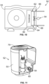
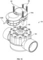
- the actuator 78A can be secured to the valve 54 by fasteners 86 such that it interfaces with a three-way spline 90 of the valve 54 that is maneuvered by the actuator 78A to position the valve 54 in the operating sates as described herein. It will be appreciated, that similar interfacing operations as described and shown for the actuator 78A are contemplated with respect to the actuator 78B. Furthermore, it should also be appreciated that the actuators 78A and 78B, the two-way valve 84, and the three way valve 88 shown in FIGS. 13-16 can be used in relation to the connected heating system 22 and the valve 34 as shown in FIGS. 1-3 .
- the heater control board 56 and/or the valve control board 82 can be coupled to various sensors and switches that monitor for and/or activate at the presence of different potential error or fault conditions for the heater 52 and can include a data connection for coupling the valve control board 82 to the valve 54.
- the valve control board 82 can be connected to the central controller 24 using an RS485 connection such as described here or the like and can communicate control signals, outputs from the various sensors and switches, and other relevant data using a customized protocol as described herein.
- the valve control board 82 can be configured only to transmit in response to a command from the central controller 24.
- valve control board 82 can ensure data integrity prior to use of the data, by using one or more of a proper address, a proper opcode, a proper packet length, and a proper checksum when compiling and transmitting data to the central controller 24.
- the controller e.g. the heater control boards 32 and 52, the central controller 24, and/or the portable user device 26
- the controller can include respective transceiver and a memory devices, each of which can be in communication with control circuitry, one or more programmable processors, and executable control software as would be understood by one of ordinary skill in the art.
- the control software can be stored on a transitory or non-transitory computer readable medium, including, but not limited to local computer memory, RAM, optical storage media, magnetic storage media, flash memory, and the like, and some or all of the control circuitry, the programmable processors, and the control software can execute and control at least some of the methods described herein.
Landscapes
- Engineering & Computer Science (AREA)
- Physics & Mathematics (AREA)
- General Engineering & Computer Science (AREA)
- Thermal Sciences (AREA)
- Chemical & Material Sciences (AREA)
- Combustion & Propulsion (AREA)
- Mechanical Engineering (AREA)
- Architecture (AREA)
- Automation & Control Theory (AREA)
- General Physics & Mathematics (AREA)
- Sustainable Development (AREA)
- Life Sciences & Earth Sciences (AREA)
- Water Supply & Treatment (AREA)
- Civil Engineering (AREA)
- Structural Engineering (AREA)
- Computer Hardware Design (AREA)
- Computer Networks & Wireless Communication (AREA)
- Steam Or Hot-Water Central Heating Systems (AREA)
- Heat-Pump Type And Storage Water Heaters (AREA)
Claims (15)
- Verbundenes Heizsystem (22) für aquatische Anwendungen, aufweisend:eine Heizvorrichtung (30) mit einer ersten Zuflussöffnung (33) und einer ersten Abflussöffnung (35);ein Steuergerät (24), das einen oder mehrere Zustände, welche die Heizvorrichtung (30) betreffen, überwacht;einen Heizvorrichtungs-Bypass (23), der zwischen die erste Zuflussöffnung (33) und die erste Abflussöffnung (35) geschaltet ist; undein Ventil (34), das einen Fluss von Wasser, das von einem Pool empfangen wird, in die erste Zuflussöffnung (33) und den Heizvorrichtungs-Bypass (23) steuert, basierend auf einem vom Steuergerät (24) identifizierten Betriebszustand,wobei das Steuergerät (24) eingerichtet ist, als Reaktion auf das Identifizieren des Betriebszustands durch das Steuergerät (24) Steuersignale zu senden, welche ein Betätigen des Ventils (34) anweisen, um den Betriebszustand zu erreichen, undwobei die Heizvorrichtung (30) eingerichtet ist, Teile des Wassers aus dem Pool zu erwärmen, die zwischen der ersten Zuflussöffnung (33) und der ersten Abflussöffnung (35) fließen, wenn ein Heizmodus aktiv ist.
- Verbundenes Heizsystem (22) gemäß Anspruch 1, wobei der Heizvorrichtungs-Bypass (23) eine zweite Zuflussöffnung (25) aufweist, die mit der ersten Zuflussöffnung (33) der Heizvorrichtung (30) gekoppelt ist, und eine zweite Abflussöffnung (27), die mit der ersten Abflussöffnung (35) der Heizvorrichtung (30) gekoppelt ist, wobei das Ventil (34) zwischen die zweite Zuflussöffnung (25) und die zweite Abflussöffnung (27) gekoppelt ist, wobei der Betriebszustand eine zeitliche Abfolge von Betätigungen des Ventils (34) zwischen einem geschlossenen Zustand und einem geöffneten Zustand aufweist, wobei das Ventil (34) in dem vollständig geschlossenen Zustand den Fluss des Wassers aus dem Pool zwischen der zweiten Zuflussöffnung (25) und der zweiten Abflussöffnung (27) blockiert, und wobei das Ventil (34) in dem vollständig geöffneten Zustand die Strömung des Wassers aus dem Pool in die erste Zuflussöffnung (33) abschwächt, indem es das aus dem Pool empfangene Wasser so lenkt, dass es sowohl in die erste Zuflussöffnung (33) der Heizvorrichtung (30) als auch in die zweite Zuflussöffnung (25) des Heizvorrichtungs-Bypasses (23) fließt.
- Verbundenes Heizsystem (22) gemäß Anspruch 1, wobei der Betriebszustand einen von mehreren Betätigungszuständen des Ventils (34) aufweist, wobei die mehreren Betätigungszustände des Ventils einen vollständig geschlossenen Zustand, einen vollständig geöffneten Zustand und einen oder mehrere Zwischenzustände einschließen, wobei das Ventil (34) in dem vollständig geschlossenen Zustand das vom Pool empfangene Wasser so lenkt, dass es in den Heizvorrichtungs-Bypass (23) fließt, indem es den Fluss in die erste Zuflussöffnung (33) blockiert, wobei in dem vollständig geöffneten Zustand das Ventil (34) es dem Wasser ermöglicht, frei in die erste Zuflussöffnung (33) zu fließen, indem es den Fluss in die Heizvorrichtungs-Bypass (23) blockiert, und wobei in dem einen oder den mehreren Zwischenzuständen das Ventil (34) den Fluss des Wassers aus dem Pool in die erste Zuflussöffnung (33) reduziert, indem es das aus dem Pool empfangene Wasser so lenkt, dass es sowohl in die Heizvorrichtungs-Bypass (23) als auch in die erste Zuflussöffnung (33) fließt.
- Verbundenes Heizsystem (22) gemäß Anspruch 1, wobei die Heizvorrichtung (30) eine Wärmepumpe enthält, die eine Heizvorrichtungssteuerkarte (32), ein Expansionsventil (74), einen Kompressor (72), einen zwischen das Expansionsventil (74) und den Kompressor (72) geschalteten Kondensator (60) einen Verdampfer (76), der zwischen dem Expansionsventil (74) und dem Kompressor (72) gekoppelt ist, ein Gebläse (70), das kühle Luft von der Heizvorrichtung (30) entfernt und Außenluft auf den Verdampfer (76) leitet, und ein Thermofluid, das eingerichtet ist, durch das Expansionsventil (74), den Kompressor (72), den Kondensator (60) und den Verdampfer (76) zu zirkulieren, aufweist, wobei der Kondensator (60) in Kontakt ist mit dem Wasser, das zwischen der ersten Zuflussöffnung (33) und der ersten Abflussöffnung (35) fließt, und wobei die Heizvorrichtungssteuerkarte (32) eingerichtet ist, das Gebläse (70), das Expansionsventil (74) und den Kompressor (72) zu aktivieren, um das Thermofluid zirkulieren zu lassen, um den Heizmodus zu aktivieren, wobei das Thermofluid während der Zirkulation zunächst durch die Außenluft, die sich auf dem Verdampfer (76) sammelt, erwärmt wird, durch Kompression durch den Kompressor (72) weiter erwärmt wird, und Wärme an das Wasser abgibt, das zwischen der ersten Zuflussöffnung (33) und der ersten Abflussöffnung (35) am Kondensator (60) fließt.
- Verbundenes Heizsystem (22) gemäß Anspruch 4, ferner aufweisend einen Wassertemperatursensor, der elektrisch mit dem Steuergerät (24) gekoppelt und eingerichtet ist, eine Temperatur des zwischen der ersten Zuflussöffnung (33) und der ersten Abflussöffnung (35) fließenden Wassers zu messen und an das Steuergerät (24) weiterzuleiten, und wobei, wenn das Steuergerät (24) feststellt, dass die Temperatur des Wassers unter einem ersten vorkonfigurierten Schwellenwert liegt, die Heizvorrichtungssteuerkarte (32) den Heizmodus einschaltet, und wobei, wenn das Steuergerät (24) feststellt, dass die Temperatur des Wassers über einem zweiten vorkonfigurierten Schwellenwert liegt, die Heizvorrichtungssteuerkarte (32) den Heizmodus ausschaltet.
- Verbundenes Heizsystem (22) gemäß Anspruch 4, wobei das Steuergerät (24) den einen oder die mehreren Zustände, welche die Heizvorrichtung (30) betreffen (30), analysiert, um einen aktuellen Leistungskoeffizienten (COP) der Wärmepumpe zu ermitteln, und wobei das Steuergerät (24), wenn der aktuelle COP kleiner als ein maximaler COP ist, den Betriebszustand für das Ventil (34) als einen identifiziert, bei dem das Ventil (34) den Fluss des vom Pool empfangenen Wassers in die erste Zuflussöffnung (33) und den Heizvorrichtungs-Bypass (23) steuert, um den aktuellen COP auf den maximalen COP zu ändern.
- Verbundenes Heizsystem (22) gemäß Anspruch 6, ferner aufweisend ein Gehäuse (31), welches die Heizvorrichtungssteuerkarte (32), das Expansionsventil (74), den Kompressor (72), den Kondensator (60), den Verdampfer (76), das Gebläse (70), das Ventil (34) und den Heizvorrichtungs-Bypass (23) aufweist,wobei der Heizvorrichtungs-Bypass (23) eine zweite Zuflussöffnung (25) aufweist, die mit der ersten Zuflussöffnung (33) der Heizvorrichtung (30) verbunden ist, und eine zweite Abflussöffnung (27), die mit der ersten Abflussöffnung (35) der Heizvorrichtung (30) verbunden ist,wobei das Ventil (34) zwischen die zweite Zuflussöffnung (25) und die zweite Abflussöffnung (27) gekoppelt ist,wobei der Betriebszustand eine zeitliche Abfolge von Betätigungen des Ventils (34) zwischen einem geschlossenen Zustand und einem offenen Zustand aufweist,wobei das Ventil (34) in dem geschlossenen Zustand den Durchfluss des Wassers aus dem Pool zwischen der zweiten Zuflussöffnung (25) und der zweiten Abflussöffnung (27) blockiert,wobei das Ventil (34) im geöffneten Zustand die Strömung des Wassers aus dem Pool in die erste Zuflussöffnung (33) abschwächt, indem es das aus dem Pool empfangene Wasser so lenkt, dass es sowohl in die erste Zuflussöffnung (33) der Heizvorrichtung (30) als auch in die zweite Zuflussöffnung (25) des Heizvorrichtungs-Bypasses (23) fließt, undwobei das Steuergerät (24), das den Betriebszustand identifiziert, um den aktuellen COP auf den maximalen COP einzustellen, das Steuergerät (24) aufweist, welches eine neue zeitliche Abfolge von Betätigungen des Ventils (34) zwischen dem geschlossenen Zustand und dem geöffneten Zustand identifiziert.
- Verbundenes Heizsystem (22) gemäß Anspruch 7, wobei der eine oder die mehreren Zustände mindestens einen aufweisen von einer jeweiligen Temperatur des Wassers an der ersten Zuflussöffnung (33) und der ersten Abflussöffnung (35), einer Kondensationstemperatur und einem Druck an einem Auslass des Kompressors (72).
- Verbundenes Heizsystem (22) gemäß Anspruch 8, ferner aufweisend eine Mehrzahl von Sensoren (39), die jeweils einem oder mehreren des einen oder der mehreren Zustände entsprechen, die vom Steuergerät (24) überwacht werden, wobei die Mehrzahl von Sensoren (39) mindestens einen Temperatursensor, einen Drucksensor und einen Durchflussratenmonitor aufweist.
- Verbundenes Heizsystem (22) gemäß Anspruch 4, wobei die Heizvorrichtungssteuerkarte (32) das Steuergerät (24) aufweist.
- Verbundenes Heizsystem (22) gemäß Anspruch 4, wobei das Steuergerät (24) elektrisch mit der Heizvorrichtungssteuerkarte (32) mittels mindestens einem von einem drahtgebundenen Medium oder einem drahtlosen Medium verbunden ist.
- Verbundenes Heizsystem (22) gemäß Anspruch 1, ferner aufweisend einen Aktuator (78A), der mit dem Ventil (34) verbunden und elektrisch mit dem Steuergerät (24) gekoppelt ist, wobei der Aktuator (78A) eingerichtet ist, das Ventil (34) als Reaktion auf den Empfang der Steuersignale von dem Steuergerät (24) in den Betriebszustand zu bewegen.
- Verfahren zum Betreiben einer Wärmepumpe, aufweisend:Überwachen eines oder mehrerer Zustände, welche eine Wärmepumpe betreffen, mittels eines Steuergeräts (24);Analysieren des einen oder der mehreren Zustände, welche die Wärmepumpe betreffen, mittels des Steuergeräts (24), um einen aktuellen Leistungskoeffizienten (COP) der Wärmepumpe zu ermitteln;Identifizieren, mittels des Steuergeräts (24), eines Betriebszustands für ein Ventil (34), das den aktuellen COP auf einen maximalen COP einstellt, wenn der aktuelle COP kleiner als der maximale COP ist;Übertragen von Steuersignalen, welche eine Betätigung des Ventils (34) dirigieren, um den Betriebszustand zu erreichen, vom Steuergerät (24) an einen Aktuator (78A) für das Ventil (34);Betätigen des Ventils (34) in den Betriebszustand mittels des Aktuators (78A) in Reaktion auf den Empfang der Steuersignale vom Steuergerät (24) mittels des Aktuators (78A); undSteuern des Flusses von Wasser, das von einem Pool empfangen wird, in eine erste Zuflussöffnung (33) der Wärmepumpe und eine zweite Zuflussöffnung (25) eines Heizvorrichtungs-Bypasses (23) mittels des Ventils (34), um den aktuellen COP auf den maximalen COP einzustellen, wenn das Ventil (34) in den Betriebszustand bewegt wird.
- Verfahren gemäß Anspruch 13, wobei der Betriebszustand eine zeitliche Abfolge von Betätigungen des Ventils (34) zwischen einem geschlossenen Zustand und einem offenen Zustand aufweist,wobei das Ventil (34) im geschlossenen Zustand den Fluss des Wassers aus dem Pool zwischen der zweiten Zuflussöffnung (25) des Heizvorrichtungs-Bypasses (23) und einer zweiten Abflussöffnung (27) des Heizvorrichtungs-Bypasses (23) blockiert,wobei das Ventil (34) im geöffneten Zustand den Fluss des Wassers aus dem Pool in die erste Zuflussöffnung (33) verringert, indem es das aus dem Pool empfangene Wasser so lenkt, dass es sowohl in die erste Zuflussöffnung (33) der Heizvorrichtung (30) als auch in die zweite Zuflussöffnung (25) des Heizvorrichtungs-Bypasses (23) fließt, undwobei das Steuergerät (24), welches den Betriebszustand identifiziert, um den aktuellen COP auf den maximalen COP einzustellen, das Steuergerät (24) aufweist, welches eine neue zeitliche Abfolge von Betätigungen des Ventils (34) zwischen dem geschlossenen Zustand und dem geöffneten Zustand identifiziert.
- Verfahren gemäß Anspruch 13, wobei der eine oder die mehreren Zustände mindestens einen der folgenden aufweisen: eine jeweilige Temperatur des Wassers an der ersten Zuflussöffnung (33) der Wärmepumpe und einer ersten Abflussöffnung (35) der Wärmepumpe, eine Kondensationstemperatur und einen Druck an einem Auslass eines Kompressors (72) der Wärmepumpe.
Applications Claiming Priority (1)
| Application Number | Priority Date | Filing Date | Title |
|---|---|---|---|
| US202163200024P | 2021-02-10 | 2021-02-10 |
Publications (2)
| Publication Number | Publication Date |
|---|---|
| EP4043672A1 EP4043672A1 (de) | 2022-08-17 |
| EP4043672B1 true EP4043672B1 (de) | 2025-06-18 |
Family
ID=80447863
Family Applications (1)
| Application Number | Title | Priority Date | Filing Date |
|---|---|---|---|
| EP22156091.5A Active EP4043672B1 (de) | 2021-02-10 | 2022-02-10 | Becken und kurbadheizsystem |
Country Status (3)
| Country | Link |
|---|---|
| US (2) | US12385270B2 (de) |
| EP (1) | EP4043672B1 (de) |
| ES (1) | ES3043207T3 (de) |
Families Citing this family (7)
| Publication number | Priority date | Publication date | Assignee | Title |
|---|---|---|---|---|
| MX386760B (es) * | 2014-06-20 | 2025-03-19 | Pentair Water Pool & Spa Inc | Calentador híbrido. |
| US10925804B2 (en) | 2017-10-04 | 2021-02-23 | Sundance Spas, Inc. | Remote spa control system |
| US12392525B2 (en) | 2020-10-09 | 2025-08-19 | Rheem Manufacturing Company | Electronic temperature limiting control |
| AU2022331242A1 (en) * | 2021-08-17 | 2024-02-22 | Zodiac Pool Systems Llc | Heater for pools and spas with improved sensor control |
| PL245683B1 (pl) * | 2022-11-02 | 2024-09-16 | Univ Warminsko Mazurski W Olsztynie | Układ do sterowania podgrzewaniem i filtrowaniem wody w basenie ogrodowym |
| NO20241128A1 (no) * | 2023-11-15 | 2025-05-16 | Kenneth Sleire | Oppvarmingssystem for spabad og basseng |
| US20250198185A1 (en) * | 2023-12-18 | 2025-06-19 | Zodiac Pool Systems Llc | Swimming pool and spa with improved heating modes |
Family Cites Families (10)
| Publication number | Priority date | Publication date | Assignee | Title |
|---|---|---|---|---|
| US4279128A (en) * | 1979-04-30 | 1981-07-21 | Alfred R. Edwards | Heat pump swimming pool heater |
| AUPM835894A0 (en) * | 1994-09-22 | 1994-10-13 | Thermal Energy Accumulator Products Pty Ltd | A temperature control system for liquids |
| US5577661A (en) * | 1995-08-21 | 1996-11-26 | Anser, Inc. | Pool water heating and circulating system |
| US6695970B2 (en) * | 2002-07-03 | 2004-02-24 | Ike W. Hornsby | Actuated bypass valve and method of using same for reducing swimming pool energy consumption |
| US20090039030A1 (en) * | 2007-08-06 | 2009-02-12 | Revak Conrad S | Antimicrobial water treatment system and method |
| US20130291948A1 (en) * | 2012-03-28 | 2013-11-07 | Zodiac Pool Systems, Inc. | Head loss reducing device for a swimming pool water heater, heat pump, or other heating product for pools or spas |
| FR3009612B1 (fr) * | 2013-08-09 | 2018-12-07 | Zodiac Pool Care Europe | Systeme et procede de pilotage d'une pompe a chaleur pour piscine |
| US20150260428A1 (en) * | 2014-03-14 | 2015-09-17 | Joshua Haldeman | Pool water heater |
| MX386760B (es) * | 2014-06-20 | 2025-03-19 | Pentair Water Pool & Spa Inc | Calentador híbrido. |
| EP3405629A4 (de) * | 2016-01-22 | 2020-01-22 | Hayward Industries, Inc. | Systeme und verfahren zur bereitstellung von netzwerkkonnektivität und fernüberwachung, optimierung und steuerung einer pool-/spa-ausrüstung |
-
2022
- 2022-02-10 EP EP22156091.5A patent/EP4043672B1/de active Active
- 2022-02-10 ES ES22156091T patent/ES3043207T3/es active Active
- 2022-02-10 US US17/650,611 patent/US12385270B2/en active Active
-
2025
- 2025-08-11 US US19/296,227 patent/US20250369245A1/en active Pending
Also Published As
| Publication number | Publication date |
|---|---|
| US20250369245A1 (en) | 2025-12-04 |
| EP4043672A1 (de) | 2022-08-17 |
| US20220251861A1 (en) | 2022-08-11 |
| US12385270B2 (en) | 2025-08-12 |
| ES3043207T3 (en) | 2025-11-25 |
Similar Documents
| Publication | Publication Date | Title |
|---|---|---|
| EP4043672A1 (de) | Becken und kurbadheizsystem | |
| US11686118B2 (en) | Hybrid heater | |
| US7335856B2 (en) | Apparatus and method of detecting igniter type | |
| US20200088336A1 (en) | Controller, Method of Operating a Water Source Heat Pump and a Water Source Heat Pump | |
| CN102119278B (zh) | 具有循环泵组的加热设备或空调设备 | |
| CN104633842B (zh) | 供热和/或冷却系统的调节方法和用于该系统的配送装置 | |
| EP2728266A1 (de) | Steuervorrichtung für Wassererhitzer | |
| CN113124559A (zh) | 一种便于洗浴和采暖同时运行的壁挂炉控制系统 | |
| KR100633593B1 (ko) | 보일러 연동 온도조절 시스템과 그 시스템에 이용되는보일러용 난방수 회수관 | |
| AU2007203198B2 (en) | Improvements in Water Heating Systems | |
| JP3867771B2 (ja) | 給湯装置 | |
| CN111735158B (zh) | 供热水装置 | |
| CN110908413B (zh) | 温控器、主控器、温度调节系统及其控制方法 | |
| CN217899973U (zh) | 一种水泵组件及混水调温系统 | |
| JP7597585B2 (ja) | ボイラ装置 | |
| KR100423222B1 (ko) | 난방용 보일러 제어장치 | |
| JP2008082633A (ja) | 給湯装置とプレート式熱交換器 | |
| JP2003042547A (ja) | 給湯装置 |
Legal Events
| Date | Code | Title | Description |
|---|---|---|---|
| PUAI | Public reference made under article 153(3) epc to a published international application that has entered the european phase |
Free format text: ORIGINAL CODE: 0009012 |
|
| STAA | Information on the status of an ep patent application or granted ep patent |
Free format text: STATUS: THE APPLICATION HAS BEEN PUBLISHED |
|
| AK | Designated contracting states |
Kind code of ref document: A1 Designated state(s): AL AT BE BG CH CY CZ DE DK EE ES FI FR GB GR HR HU IE IS IT LI LT LU LV MC MK MT NL NO PL PT RO RS SE SI SK SM TR |
|
| STAA | Information on the status of an ep patent application or granted ep patent |
Free format text: STATUS: REQUEST FOR EXAMINATION WAS MADE |
|
| 17P | Request for examination filed |
Effective date: 20230217 |
|
| RBV | Designated contracting states (corrected) |
Designated state(s): AL AT BE BG CH CY CZ DE DK EE ES FI FR GB GR HR HU IE IS IT LI LT LU LV MC MK MT NL NO PL PT RO RS SE SI SK SM TR |
|
| GRAP | Despatch of communication of intention to grant a patent |
Free format text: ORIGINAL CODE: EPIDOSNIGR1 |
|
| STAA | Information on the status of an ep patent application or granted ep patent |
Free format text: STATUS: GRANT OF PATENT IS INTENDED |
|
| RIC1 | Information provided on ipc code assigned before grant |
Ipc: E04H 4/12 20060101AFI20240308BHEP |
|
| INTG | Intention to grant announced |
Effective date: 20240328 |
|
| GRAJ | Information related to disapproval of communication of intention to grant by the applicant or resumption of examination proceedings by the epo deleted |
Free format text: ORIGINAL CODE: EPIDOSDIGR1 |
|
| STAA | Information on the status of an ep patent application or granted ep patent |
Free format text: STATUS: REQUEST FOR EXAMINATION WAS MADE |
|
| P01 | Opt-out of the competence of the unified patent court (upc) registered |
Free format text: CASE NUMBER: APP_42932/2024 Effective date: 20240722 |
|
| INTC | Intention to grant announced (deleted) | ||
| GRAP | Despatch of communication of intention to grant a patent |
Free format text: ORIGINAL CODE: EPIDOSNIGR1 |
|
| STAA | Information on the status of an ep patent application or granted ep patent |
Free format text: STATUS: GRANT OF PATENT IS INTENDED |
|
| INTG | Intention to grant announced |
Effective date: 20250109 |
|
| GRAS | Grant fee paid |
Free format text: ORIGINAL CODE: EPIDOSNIGR3 |
|
| GRAA | (expected) grant |
Free format text: ORIGINAL CODE: 0009210 |
|
| STAA | Information on the status of an ep patent application or granted ep patent |
Free format text: STATUS: THE PATENT HAS BEEN GRANTED |
|
| AK | Designated contracting states |
Kind code of ref document: B1 Designated state(s): AL AT BE BG CH CY CZ DE DK EE ES FI FR GB GR HR HU IE IS IT LI LT LU LV MC MK MT NL NO PL PT RO RS SE SI SK SM TR |
|
| REG | Reference to a national code |
Ref country code: GB Ref legal event code: FG4D |
|
| REG | Reference to a national code |
Ref country code: CH Ref legal event code: EP |
|
| REG | Reference to a national code |
Ref country code: DE Ref legal event code: R096 Ref document number: 602022015957 Country of ref document: DE |
|
| REG | Reference to a national code |
Ref country code: CH Ref legal event code: EP |
|
| REG | Reference to a national code |
Ref country code: IE Ref legal event code: FG4D |
|
| REG | Reference to a national code |
Ref country code: CH Ref legal event code: PK Free format text: BERICHTIGUNGEN |
|
| RIN2 | Information on inventor provided after grant (corrected) |
Inventor name: DURAND, MICHEL Inventor name: LE LAY, YVES-MARIE Inventor name: DE JERPHANION, MARTIN Inventor name: COLOMB, STEPHANE Inventor name: VAUGHN, DAVID Inventor name: FETEN, EDWARD Inventor name: PICKARD, ZACHARY STEVEN Inventor name: MOYA-MENDEZ, JACOB |
|
| PG25 | Lapsed in a contracting state [announced via postgrant information from national office to epo] |
Ref country code: FI Free format text: LAPSE BECAUSE OF FAILURE TO SUBMIT A TRANSLATION OF THE DESCRIPTION OR TO PAY THE FEE WITHIN THE PRESCRIBED TIME-LIMIT Effective date: 20250618 |
|
| REG | Reference to a national code |
Ref country code: LT Ref legal event code: MG9D |
|
| PG25 | Lapsed in a contracting state [announced via postgrant information from national office to epo] |
Ref country code: NO Free format text: LAPSE BECAUSE OF FAILURE TO SUBMIT A TRANSLATION OF THE DESCRIPTION OR TO PAY THE FEE WITHIN THE PRESCRIBED TIME-LIMIT Effective date: 20250918 Ref country code: GR Free format text: LAPSE BECAUSE OF FAILURE TO SUBMIT A TRANSLATION OF THE DESCRIPTION OR TO PAY THE FEE WITHIN THE PRESCRIBED TIME-LIMIT Effective date: 20250919 |
|
| PG25 | Lapsed in a contracting state [announced via postgrant information from national office to epo] |
Ref country code: BG Free format text: LAPSE BECAUSE OF FAILURE TO SUBMIT A TRANSLATION OF THE DESCRIPTION OR TO PAY THE FEE WITHIN THE PRESCRIBED TIME-LIMIT Effective date: 20250618 |
|
| PG25 | Lapsed in a contracting state [announced via postgrant information from national office to epo] |
Ref country code: HR Free format text: LAPSE BECAUSE OF FAILURE TO SUBMIT A TRANSLATION OF THE DESCRIPTION OR TO PAY THE FEE WITHIN THE PRESCRIBED TIME-LIMIT Effective date: 20250618 |
|
| PG25 | Lapsed in a contracting state [announced via postgrant information from national office to epo] |
Ref country code: RS Free format text: LAPSE BECAUSE OF FAILURE TO SUBMIT A TRANSLATION OF THE DESCRIPTION OR TO PAY THE FEE WITHIN THE PRESCRIBED TIME-LIMIT Effective date: 20250918 |
|
| REG | Reference to a national code |
Ref country code: NL Ref legal event code: MP Effective date: 20250618 |
|
| PG25 | Lapsed in a contracting state [announced via postgrant information from national office to epo] |
Ref country code: LV Free format text: LAPSE BECAUSE OF FAILURE TO SUBMIT A TRANSLATION OF THE DESCRIPTION OR TO PAY THE FEE WITHIN THE PRESCRIBED TIME-LIMIT Effective date: 20250618 |
|
| PG25 | Lapsed in a contracting state [announced via postgrant information from national office to epo] |
Ref country code: NL Free format text: LAPSE BECAUSE OF FAILURE TO SUBMIT A TRANSLATION OF THE DESCRIPTION OR TO PAY THE FEE WITHIN THE PRESCRIBED TIME-LIMIT Effective date: 20250618 |
|
| REG | Reference to a national code |
Ref country code: ES Ref legal event code: FG2A Ref document number: 3043207 Country of ref document: ES Kind code of ref document: T3 Effective date: 20251125 |
|
| PG25 | Lapsed in a contracting state [announced via postgrant information from national office to epo] |
Ref country code: PT Free format text: LAPSE BECAUSE OF FAILURE TO SUBMIT A TRANSLATION OF THE DESCRIPTION OR TO PAY THE FEE WITHIN THE PRESCRIBED TIME-LIMIT Effective date: 20251020 |
|
| REG | Reference to a national code |
Ref country code: AT Ref legal event code: MK05 Ref document number: 1804303 Country of ref document: AT Kind code of ref document: T Effective date: 20250618 |
|
| PG25 | Lapsed in a contracting state [announced via postgrant information from national office to epo] |
Ref country code: IS Free format text: LAPSE BECAUSE OF FAILURE TO SUBMIT A TRANSLATION OF THE DESCRIPTION OR TO PAY THE FEE WITHIN THE PRESCRIBED TIME-LIMIT Effective date: 20251018 |
|
| PG25 | Lapsed in a contracting state [announced via postgrant information from national office to epo] |
Ref country code: AT Free format text: LAPSE BECAUSE OF FAILURE TO SUBMIT A TRANSLATION OF THE DESCRIPTION OR TO PAY THE FEE WITHIN THE PRESCRIBED TIME-LIMIT Effective date: 20250618 Ref country code: SM Free format text: LAPSE BECAUSE OF FAILURE TO SUBMIT A TRANSLATION OF THE DESCRIPTION OR TO PAY THE FEE WITHIN THE PRESCRIBED TIME-LIMIT Effective date: 20250618 |
|
| PG25 | Lapsed in a contracting state [announced via postgrant information from national office to epo] |
Ref country code: CZ Free format text: LAPSE BECAUSE OF FAILURE TO SUBMIT A TRANSLATION OF THE DESCRIPTION OR TO PAY THE FEE WITHIN THE PRESCRIBED TIME-LIMIT Effective date: 20250618 |
|
| PG25 | Lapsed in a contracting state [announced via postgrant information from national office to epo] |
Ref country code: PL Free format text: LAPSE BECAUSE OF FAILURE TO SUBMIT A TRANSLATION OF THE DESCRIPTION OR TO PAY THE FEE WITHIN THE PRESCRIBED TIME-LIMIT Effective date: 20250618 |
|
| PG25 | Lapsed in a contracting state [announced via postgrant information from national office to epo] |
Ref country code: EE Free format text: LAPSE BECAUSE OF FAILURE TO SUBMIT A TRANSLATION OF THE DESCRIPTION OR TO PAY THE FEE WITHIN THE PRESCRIBED TIME-LIMIT Effective date: 20250618 |
|
| PG25 | Lapsed in a contracting state [announced via postgrant information from national office to epo] |
Ref country code: SK Free format text: LAPSE BECAUSE OF FAILURE TO SUBMIT A TRANSLATION OF THE DESCRIPTION OR TO PAY THE FEE WITHIN THE PRESCRIBED TIME-LIMIT Effective date: 20250618 |
|
| REG | Reference to a national code |
Ref country code: DE Ref legal event code: R097 Ref document number: 602022015957 Country of ref document: DE |
|
| PGFP | Annual fee paid to national office [announced via postgrant information from national office to epo] |
Ref country code: ES Payment date: 20260319 Year of fee payment: 5 |
|
| PG25 | Lapsed in a contracting state [announced via postgrant information from national office to epo] |
Ref country code: DK Free format text: LAPSE BECAUSE OF FAILURE TO SUBMIT A TRANSLATION OF THE DESCRIPTION OR TO PAY THE FEE WITHIN THE PRESCRIBED TIME-LIMIT Effective date: 20250618 |
|
| PGFP | Annual fee paid to national office [announced via postgrant information from national office to epo] |
Ref country code: FR Payment date: 20260223 Year of fee payment: 5 |
|
| PLBE | No opposition filed within time limit |
Free format text: ORIGINAL CODE: 0009261 |
|
| STAA | Information on the status of an ep patent application or granted ep patent |
Free format text: STATUS: NO OPPOSITION FILED WITHIN TIME LIMIT |
|
| REG | Reference to a national code |
Ref country code: CH Ref legal event code: L10 Free format text: ST27 STATUS EVENT CODE: U-0-0-L10-L00 (AS PROVIDED BY THE NATIONAL OFFICE) Effective date: 20260430 |