EP4043615B1 - Elektrolyseanlage - Google Patents
Elektrolyseanlage Download PDFInfo
- Publication number
- EP4043615B1 EP4043615B1 EP22156377.8A EP22156377A EP4043615B1 EP 4043615 B1 EP4043615 B1 EP 4043615B1 EP 22156377 A EP22156377 A EP 22156377A EP 4043615 B1 EP4043615 B1 EP 4043615B1
- Authority
- EP
- European Patent Office
- Prior art keywords
- unit
- electrolyzer
- electrolysis
- auxiliary
- plant
- Prior art date
- Legal status (The legal status is an assumption and is not a legal conclusion. Google has not performed a legal analysis and makes no representation as to the accuracy of the status listed.)
- Active
Links
Images


Classifications
-
- C—CHEMISTRY; METALLURGY
- C25—ELECTROLYTIC OR ELECTROPHORETIC PROCESSES; APPARATUS THEREFOR
- C25B—ELECTROLYTIC OR ELECTROPHORETIC PROCESSES FOR THE PRODUCTION OF COMPOUNDS OR NON-METALS; APPARATUS THEREFOR
- C25B1/00—Electrolytic production of inorganic compounds or non-metals
- C25B1/01—Products
- C25B1/02—Hydrogen or oxygen
- C25B1/04—Hydrogen or oxygen by electrolysis of water
-
- C—CHEMISTRY; METALLURGY
- C25—ELECTROLYTIC OR ELECTROPHORETIC PROCESSES; APPARATUS THEREFOR
- C25B—ELECTROLYTIC OR ELECTROPHORETIC PROCESSES FOR THE PRODUCTION OF COMPOUNDS OR NON-METALS; APPARATUS THEREFOR
- C25B15/00—Operating or servicing cells
-
- C—CHEMISTRY; METALLURGY
- C25—ELECTROLYTIC OR ELECTROPHORETIC PROCESSES; APPARATUS THEREFOR
- C25B—ELECTROLYTIC OR ELECTROPHORETIC PROCESSES FOR THE PRODUCTION OF COMPOUNDS OR NON-METALS; APPARATUS THEREFOR
- C25B15/00—Operating or servicing cells
- C25B15/02—Process control or regulation
- C25B15/021—Process control or regulation of heating or cooling
-
- C—CHEMISTRY; METALLURGY
- C25—ELECTROLYTIC OR ELECTROPHORETIC PROCESSES; APPARATUS THEREFOR
- C25B—ELECTROLYTIC OR ELECTROPHORETIC PROCESSES FOR THE PRODUCTION OF COMPOUNDS OR NON-METALS; APPARATUS THEREFOR
- C25B15/00—Operating or servicing cells
- C25B15/08—Supplying or removing reactants or electrolytes; Regeneration of electrolytes
-
- C—CHEMISTRY; METALLURGY
- C25—ELECTROLYTIC OR ELECTROPHORETIC PROCESSES; APPARATUS THEREFOR
- C25B—ELECTROLYTIC OR ELECTROPHORETIC PROCESSES FOR THE PRODUCTION OF COMPOUNDS OR NON-METALS; APPARATUS THEREFOR
- C25B9/00—Cells or assemblies of cells; Constructional parts of cells; Assemblies of constructional parts, e.g. electrode-diaphragm assemblies; Process-related cell features
- C25B9/70—Assemblies comprising two or more cells
-
- Y—GENERAL TAGGING OF NEW TECHNOLOGICAL DEVELOPMENTS; GENERAL TAGGING OF CROSS-SECTIONAL TECHNOLOGIES SPANNING OVER SEVERAL SECTIONS OF THE IPC; TECHNICAL SUBJECTS COVERED BY FORMER USPC CROSS-REFERENCE ART COLLECTIONS [XRACs] AND DIGESTS
- Y02—TECHNOLOGIES OR APPLICATIONS FOR MITIGATION OR ADAPTATION AGAINST CLIMATE CHANGE
- Y02E—REDUCTION OF GREENHOUSE GAS [GHG] EMISSIONS, RELATED TO ENERGY GENERATION, TRANSMISSION OR DISTRIBUTION
- Y02E60/00—Enabling technologies; Technologies with a potential or indirect contribution to GHG emissions mitigation
- Y02E60/30—Hydrogen technology
- Y02E60/36—Hydrogen production from non-carbon containing sources, e.g. by water electrolysis
Definitions
- the invention relates to an electrolysis plant for producing hydrogen by means of
- Electrolysis see claim 1. Electrolysis systems are known in practice and can be used on an industrial scale to produce or generate pure hydrogen. Basically, an electrolysis system comprises at least one electrolyzer that is connected to auxiliary systems. The electrolyzer is the part of the system in which the actual electrolysis of the reactant takes place, i.e. in which, for example, water is broken down into hydrogen and oxygen. The electrolyzer is operated electrically by applying a direct voltage.
- the auxiliary systems that are connected to the electrolyzer include, for example, devices such as a water treatment system that is connected to a reactant water line leading to the electrolyzer, a gas treatment device, a gas washing device, a storage facility for the hydrogen produced and/or the like.
- Previous electrolysis plants of the type described above which can be so-called PEM (Proton Exchange Membrane) electrolysis plants or alkaline electrolysis plants, require a very large amount of space, especially for the production of hydrogen on an industrial scale, which in turn leads to long pipes and long cables between the auxiliary plants and the electrolyzers.
- PEM Proton Exchange Membrane
- the accessibility of the individual components, especially in emergency situations, is sometimes difficult due to the complex layout and the complex geometry of the pipes and cables.
- the arrangement of the individual components of the electrolysis plant must always be adapted to the respective task. A Scaling depending on the performance of the electrolysis plant is difficult.
- WO 2020/020611 A1 discloses, according to its summary, an electrolysis unit and a method for the electrochemical decomposition of water into hydrogen and oxygen.
- the electrolysis unit comprises at least two electrolysis modules. It further comprises exactly one first gas separation device for a first product gas comprising oxygen and exactly one second gas separation device for a second product gas comprising hydrogen.
- the first gas separation device is connected to each of the at least two electrolysis modules via a first line.
- the second gas separation device is connected to each of the electrolysis modules via a second line.
- the at least two first lines have the same first length.
- the at least two second lines also have the same second length.
- the invention is based on the object of creating an electrolysis plant for the production or generation of hydrogen by means of electrolysis, which has a clear arrangement and is easily scalable depending on the desired performance.
- an electrolysis plant for producing or generating hydrogen by means of electrolysis comprising two electrolyzer units, each comprising at least one electrolyzer module, and an auxiliary plant unit, wherein the auxiliary plant unit is arranged between the electrolyzer units and is connected to both electrolyzer units via a common piping unit, so that the auxiliary plant unit is jointly assigned to both electrolyzer units.
- electrolysis system is therefore proposed in which the electrolyzer units are each made up of an electrolyzer module or of several electrolyzer modules, which can in particular be arranged next to one another.
- the electrolyzer units which can in particular be arranged symmetrically with respect to the auxiliary system unit, are connected to a common pipe unit connected to the auxiliary system unit. This makes it possible to make the pipe unit compact and in particular to make the pipes and cables that connect the auxiliary system unit and the electrolyzer units short in comparison to the electrolysis systems known to date. Direct line paths can be provided between the auxiliary system unit and the electrolyzer units. This leads to significant cost savings.
- the cables running between the components can be kept shorter than in the state of the art, which is why, due to the lower electrical Losses can be reduced by using smaller cable sizes. This also reduces the costs of the entire system. If the cable sizes are kept the same as in the state of the art, the shorter cable lengths result in better operational efficiency.
- the electrolysis system according to the invention can be easily adapted to the space available at any given time.
- the construction of the electrolyzer units from, in particular, identical electrolyzer modules makes it possible to easily adapt the electrolysis system to the desired electrical output by using a corresponding number of electrolyzer modules per electrolyzer unit.
- the electrolysis system according to the invention is therefore easily scalable.
- the electrolyzer modules of the electrolysis system according to the invention basically have a substantially identical structure and are arranged next to one another in a line within an electrolyzer unit, which enables easy laying of the required pipes of the pipe unit and the required cables.
- the electrolysis plant according to the invention can be easily adapted and scaled to changing conditions. This saves costs and time when planning and implementing a new plant or a modified plant.
- each electrolyzer unit comprises an electrolyzer module
- the components the auxiliary plant unit and the piping unit and the piping of the piping unit may need to be adjusted or scaled accordingly.
- the electrolysis system according to the invention can be an alkaline electrolysis system in which the electrolyzer modules are each connected to a feed water supply line and optionally each to a lye supply line.
- the electrolysis system according to the invention can also be designed as a so-called PEM (Proton Exchange Membrane) electrolysis system in which only water is supplied to the electrolyzers as a reactant and the electrolysis of the water takes place on a membrane.
- PEM Protein Exchange Membrane
- the electrolysis plant according to the invention can be designed with a high electrical output, which can in particular be over 10 MW.
- the electrolyzer modules each comprise the actual electrolyzer and, if applicable, components that are specific to the electrolyzer in question, for example a lye separator, a lye pump or the like.
- the piping unit is advantageously designed such that it comprises T-pieces which are connected on the one hand to the two electrolyzer units and on the other hand to the auxiliary plant unit.
- the electrolyzer modules of the electrolysis arrangement according to the invention are each expediently provided with a voltage supply which can comprise a transformer designed for the required voltage (medium voltage or low voltage) and/or a rectifier which provides the direct voltage required for the electrolyzer in question.
- a voltage supply is then provided which adapts the available supply voltage (usually medium voltage or high voltage) to the voltage required for the electrolyzer in question by means of a suitable transformer and/or a suitable rectifier.
- the electrolyzer units each comprise at least two electrolyzer modules, which are arranged next to each other.
- the electrolyzer modules can be arranged so that they are adjacent to the auxiliary plant unit or are arranged next to each other in the transverse direction relative to the symmetry axis of the electrolysis plant.
- the number of electrolyzer modules per electrolyzer unit is not limited.
- the auxiliary unit of the electrolysis system preferably comprises a water treatment device which is connected to a reactant line of the piping unit leading to the electrolyzer modules and which treats the raw water provided in order to be able to provide the electrolyzer modules with the required water quality. If necessary, an additional water tank for the treated raw water may be required, which is arranged between the water treatment device and the reactant line.
- the auxiliary system unit preferably comprises a lye tank which is connected to a lye line of the piping unit which leads to the electrolyzer units.
- the lye stored in the lye tank is required for commissioning, maintenance and replacement of the lye in the electrolyzer modules.
- the auxiliary plant unit comprises a hydrogen storage unit which is connected to a hydrogen delivery line which is directly or indirectly connected to a product line of the piping unit.
- the product gas hydrogen can therefore be stored in the hydrogen storage unit.
- a hydrogen processing device can be provided which is connected upstream of the hydrogen delivery line.
- a gas scrubber for the hydrogen produced is also arranged upstream of the hydrogen delivery line. In the gas scrubber, any lye is washed out of the product gas hydrogen during alkaline electrolysis and then fed back to the electrolyzers together with the feed water. All of these elements are preferably elements that are part of the common central auxiliary plant unit.
- the electrolysis plant according to the invention can also comprise an oxygen storage arranged in the auxiliary plant unit, which is connected to an oxygen delivery line and serves to store the other product gas, oxygen.
- An oxygen processing device and/or a gas scrubber for the oxygen produced can be arranged upstream of the oxygen delivery line.
- the product gas storage can be omitted if the product gases produced are taken directly. If the oxygen shown is not used, the oxygen storage and the oxygen delivery line can of course be omitted. The oxygen preparation facility and the gas scrubber for oxygen can then also be omitted.
- the auxiliary plant unit of the electrolysis plant can comprise a gas processing device which is connected to the hydrogen discharge line.
- a corresponding gas processing device can be provided for oxygen, which is the other product gas.
- the gas processing devices can comprise components for drying the product gases and for other post-treatment of the product gases.
- the auxiliary plant unit for the product gases can comprise a compression device, which can be connected to the respective gas processing device. This allows the product gases to be provided with the gas pressure required in each case.
- the auxiliary system unit comprises a nitrogen storage unit which is connected to a nitrogen line of the piping unit.
- An inert gas in the form of nitrogen can be supplied to the electrolyzer units via the nitrogen line, for example for system flushing.
- Nitrogen can be stored in liquid or gaseous form. If the nitrogen is stored in liquid form, a nitrogen evaporator is also required. Other peripheral components designed in the usual way ensure that the nitrogen is provided for system flushing at a defined volume flow, in a defined pressure range, in a defined temperature range and with a defined quality at the relevant points in the electrolysis system.
- the auxiliary plant unit preferably further comprises a control and/or monitoring device for components of the auxiliary plant unit and components of the electrolyzer modules. It is conceivable that the control and/or monitoring device, which controls the operation of the electrolysis plant, is additionally connected to a remote control and/or monitoring device of the operator of the electrolysis plant, which is arranged outside the actual electrolysis plant.
- the auxiliary plant unit of the electrolysis plant preferably comprises an air conditioning device for the electrolyzer modules, which can comprise a heating device, a cooling device and/or a ventilation device.
- the electrolysis system comprises a cooling device for the electrolyzer modules, which is connected to the piping unit, so that the electrolyzer modules can be cooled during operation using a coolant via corresponding piping.
- the cooling device Since the cooling device requires a lot of space when the electrolysis system is designed on an industrial scale, it is preferably arranged in a separate unit that is arranged outside the electrolyzer units and outside the auxiliary plant unit. It is expedient if the cooling device is arranged on a roof of a building of the electrolysis system and/or in the immediate vicinity of at least one of the electrolyzer units or the auxiliary plant unit, whereby cooling water lines can be kept short.
- the cooling device can also be used to cool components of the auxiliary plant unit.
- the electrolyzer modules are arranged under a roof of the respective electrolyzer unit.
- the electrolyzer modules are arranged in a lightweight building of the electrolysis system, which preferably adjoins a part of the building in which a rectifier and/or a transformer of the respective electrolyzer module can be arranged.
- the auxiliary plant unit can comprise a covered interior area and/or an exterior area that is open at the top.
- Storage facilities, tanks, gas scrubbers, gasometers and/or the like can be arranged in the exterior area that is open at the top.
- the covered interior area which is preferably formed from a solid building, for example the control and/or monitoring device, the water treatment device, the air conditioning device, compressors for gas compression, gas treatment devices, gas analysis components and/or the like are arranged.
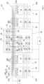
- an electrolysis plant 10 (not part of the invention) is shown, which has a modular structure and comprises a secondary plant unit 12 in a central arrangement, next to which an electrolyzer unit 14A or 14B is arranged on both sides in a symmetrical arrangement.
- the electrolyzer units 14A and 14B which each comprise an electrolyzer module 16 with an alkali electrolyzer 18, the product gases hydrogen H 2 and oxygen O 2 are produced starting from reactant water or feed water VE.
- the electrolyzer units 14A and 14B are connected to the auxiliary plant unit 12 via a common pipeline unit 20 and cables (not shown in detail).
- the pipeline unit 20 comprises a plurality of pipelines which are routed via so-called pipe bridges 22A and 22B from the auxiliary plant unit 12 to the electrolyzer units 14A and 14B.
- the electrolyzer modules 16 are each connected to a voltage supply which is connected to a central high-voltage transformer 24 which is provided with a switchgear and transforms a high-voltage alternating voltage into a medium-voltage alternating voltage.
- the medium voltage output by the high-voltage transformer 24 is converted by means of a medium-voltage transformer 26, which is assigned to the respective electrolyzer module 16, into a lower medium voltage or into a low voltage, which is converted by means of a respective rectifier 28 into a direct voltage which is provided or required for the operation of the respective electrolyzer 18.
- the medium-voltage transformers 26 are arranged in an outer area of the respective electrolyzer unit 14A or 14B.
- the rectifiers 28 are arranged in a solid construction part of the building, which adjoins a lightweight construction part in which the respective electrolyzer 18 is arranged.
- the switchgear of the high-voltage transformer 24 serves to distribute the voltages to the various medium-voltage transformers 26 and a medium-voltage transformer 30 of the auxiliary system unit 12.
- the medium-voltage transformer 30 of the auxiliary system unit 12 outputs a low voltage, which can be distributed to the relevant components of the electrolysis system 10 by means of a low-voltage sub-distribution device 31. Depending on the required electrical connection power, it is conceivable that these components are also operated directly with medium voltage.
- the auxiliary plant unit 12 comprises an outdoor area 32, which is open at the top, i.e. is not covered, and an indoor area 34, which is arranged in a solidly constructed building with a roof.
- a water treatment device 36 is arranged, which is connected to two gas scrubbers 40 and 42 via a line 38.
- the gas scrubber 40 which is arranged in the exterior area 32 of the auxiliary plant unit 12, is in turn connected via a line 44 to a T-piece 46, which is arranged in an educt line 48, which carries feed water VE as educt to the electrolyzers 18.
- a control and monitoring device 56 for the components of the electrolysis system 10 and an air conditioning device 58 are also arranged, by means of which the individual components of the electrolysis system 10 can be heated, cooled and/or ventilated.
- a compressed air generation device 60 with corresponding peripheral elements is arranged in the interior area 34, which is connected via a compressed air line 62 to a T-piece 46 of a compressed air line 64 of the pipe unit 20, wherein the compressed air DL guided in the compressed air line 62 can be used to switch the valves of the electrolysis system 10 (not shown in more detail).
- the compressed air generation device 60 ensures that the compressed air is provided with a defined volume flow, a defined pressure, a defined temperature and a defined quality at the relevant interfaces or valves of the electrolysis system 10.
- the interior area 34 of the auxiliary plant unit 12 further comprises a compressor 66, a gas processing device 68 and a gas analysis device 70 for the product gas hydrogen H 2 and a compressor 72, a gas processing device 74 and a gas analysis device 76 for the product gas oxygen O 2 .
- a hydrogen discharge line 78 branches off from the gas processing device 68 for hydrogen H 2 , which leads into the outer area 32 of the auxiliary system unit 12 and is connected to a hydrogen storage unit 80.
- An oxygen discharge line 82 branches off from the gas processing device 74 for oxygen O 2 , which is connected to an oxygen storage unit 84 arranged in the outer area 32.
- a lye tank 50 which is connected via a line 52 to a T-piece 46 of a lye line 54, via which lye can be supplied to the electrolyzers 18.
- a nitrogen storage device 86 with corresponding peripheral devices is arranged in the outer region 32 of the auxiliary plant unit 12, which is connected via a line 88 to a T-piece 46 of a nitrogen line 91, via which nitrogen N 2 can be supplied to the electrolyzers 18 as an inert gas for system flushing.
- a gasometer 90 is assigned to the gas scrubber 40 for hydrogen H 2 in the external area 32 of the auxiliary plant unit 12, which serves to ensure a constant gas pressure and as a buffer, wherein a product line 92 branches off between the gas scrubber 40 and the gasometer 90, which leads to the compressor 66 for hydrogen H 2 .
- the gas scrubber 42 for oxygen O 2 is assigned a gasometer 94, which also serves to ensure a constant gas pressure and as a buffer, wherein a product line 96 branches off between the gas scrubber 42 and the gasometer 94, which leads to the compressor 72 for oxygen O 2 .
- a cooling device 98 is arranged, which is connected to a coolant line 100 of the piping unit 20, via which coolant KM can be supplied to the electrolyzers 18.
- a hydrogen product line 102 branches off from the electrolyzers 18 and is connected to the gas scrubber 40 for hydrogen H 2 via a T-piece 46.
- an oxygen product line 104 branches off from the electrolyzers 18 and is connected to the gas scrubber 42 for oxygen O 2 via a T-piece 46.
- feed water VE is provided by the water treatment device 36 to produce hydrogen H 2 and oxygen O 2 and is passed through the gas scrubbers 40 and 42.
- the feed water VE passed through the gas scrubber 40 is fed via the reactant line 48 to the electrolyzers 18, each of which is filled with lye (in particular KOH) as an electrolyte.
- lye in particular KOH
- the direct current provided by the rectifiers 28 is used for electrolysis in the electrolyzers 18, so that hydrogen H 2 can be discharged via the product line 102 and oxygen O 2 via the product line 104.
- the hydrogen which is still contaminated with residual lye, is passed through the gas scrubber 40 and then fed to the gas processing device 68 via the line 92 and the compressor 66.
- the hydrogen storage device 80 From there it is fed to the hydrogen storage device 80 via the hydrogen discharge line 78.
- the gas scrubber 40 the residual lye is separated from the hydrogen H 2 by the water passed through in countercurrent and is returned to the electrolyzers 18 via the reactant line 48 together with the feed water VE.
- the oxygen O 2 produced by the electrolyzers 18 is fed to the gas scrubber 42 via the product line 104 and from there to the gas processing device 74 via the product line 96 and the compressor 72. From there, the oxygen O 2 purified of residual lye in the gas scrubber 42 is fed to the oxygen storage unit 84 via the oxygen discharge line 82. This residual lye is also fed back to the electrolyzers 18 together with the feed water VE. In the gas processing devices 68 and 74, the product gases hydrogen H 2 and oxygen O 2 are processed and further purified in order to achieve the required gas quality.
- the gas analysis devices 70 and 76 are used to check the quality of the product gases hydrogen H 2 and oxygen O 2 .
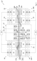
- an electrolysis plant 10' according to the invention is shown, which corresponds to the electrolysis plant according to Figure 1 a central auxiliary plant unit 12 and, with respect to an axis of symmetry of the electrolysis plant 10, an electrolyzer unit 14A or 14B on each side of the auxiliary plant unit 12.
- the electrolysis plant 10' represents a second stage of development, since the electrolyzer units 14A and 14B each comprise two electrolyzer modules 16 arranged next to one another, which are arranged in the manner according to the Figure 1 described type are connected to the central auxiliary unit 12 via a common pipe unit 20'.
- the corresponding pipes 48, 54, 64, 91, 100, 102 and 104 have additional T-pieces 106.
- the electrolyzer system 10' corresponds in terms of function and structure to that according to Figure 1 , which is why reference is made to the relevant description.
- an alkaline electrolysis plant 10" according to the invention is shown, which represents a third stage of development and also comprises a central auxiliary plant unit 12, which comprises an electrolyzer unit 14A and 14B on both sides with respect to an axis of symmetry of the plant 10", but which has four electrolyzer modules 16 with the Figure 1
- the four electrolyzer modules 16 are connected via T-pieces 108 and crossovers 110 to a common pipe unit 20" which connects the electrolyzer modules 16 to the auxiliary plant unit 12.
- the auxiliary plant unit 12 corresponds to the structure of the auxiliary plant unit according to Figure 1 .
- the structure and function of the electrolyzer system 10" also correspond to the structure and function of the electrolysis system according to Figure 1 , which is why reference is made to the relevant description.
- FIG 4 a second expansion stage of a PEM electrolysis plant 120 (not part of the invention) is shown, which also comprises a central auxiliary plant unit 12, which is arranged between two electrolyzer units 14A and 14B, each of which comprises two electrolyzer modules 16, whose electrolyzers 18 are each designed as PEM electrolyzers, in which water is decomposed at a membrane into hydrogen H 2 and oxygen O 2 and which operates without alkali.
- a central auxiliary plant unit 12 which is arranged between two electrolyzer units 14A and 14B, each of which comprises two electrolyzer modules 16, whose electrolyzers 18 are each designed as PEM electrolyzers, in which water is decomposed at a membrane into hydrogen H 2 and oxygen O 2 and which operates without alkali.
- the auxiliary plant unit 12 differs from the auxiliary plant unit of the embodiments according to the Figures 1 to 3 This is because no lye tank and no gas scrubbers with gasometers are arranged in the outside area 32. Rather, the product gases hydrogen H 2 and oxygen O 2 produced by the electrolyzers 18 are fed directly to the corresponding gas processing devices 68 and 74 via the hydrogen product line 102 and the oxygen product line 104 and via corresponding T-pieces 46 of the pipeline unit 20.
- the feed water VE (if necessary, fully demineralized water) produced by the water treatment plant 36 is led directly, without the interposition of gas scrubbers, via a T-piece 46 into the reactant line 48 and made available to the electrolyzers 18 for electrolysis.
- the structure of the electrolysis plant 120 essentially corresponds to the structure of the electrolysis plant according to Figure 2 , which is why, in order to avoid repetition, reference is made to the relevant description or the description of the electrolysis plant according to Figure 1 is referred to.
- a compressor is also required upstream of the gas processing equipment.
- the PEM electrolysis system can comprise only one electrolyzer module 16 per electrolyzer unit 14A and 14B in a first expansion stage.
- the PEM electrolysis system can comprise only one electrolyzer module 16 in accordance with the embodiment according to Figure 3 also include four electrolyzer modules 16 per electrolyzer unit. Expansion stages with three electrolyzer modules arranged next to each other or with a different number of electrolyzer modules per electrolyzer unit are also conceivable.
Landscapes
- Chemical & Material Sciences (AREA)
- Engineering & Computer Science (AREA)
- Chemical Kinetics & Catalysis (AREA)
- Electrochemistry (AREA)
- Materials Engineering (AREA)
- Metallurgy (AREA)
- Organic Chemistry (AREA)
- Automation & Control Theory (AREA)
- Inorganic Chemistry (AREA)
- Electrolytic Production Of Non-Metals, Compounds, Apparatuses Therefor (AREA)
Description
- Die Erfindung betrifft eine Elektrolyseanlage zur Darstellung von Wasserstoff mittels
- Elektrolyse, siehe Anspruch 1. Elektrolyseanlagen sind aus der Praxis bekannt und können im industriellen Maßstab zur Darstellung bzw. Erzeugung von reinem Wasserstoff eingesetzt werden. Grundsätzlich umfasst eine Elektrolyseanlage mindestens einen Elektrolyseur, der mit Nebenanlagen verbunden ist. Der Elektrolyseur ist der Teil der Anlage, in dem die eigentliche Elektrolyse des Edukts stattfindet, das heißt, in dem beispielsweise eine Zerlegung von Wasser in Wasserstoff und Sauerstoff erfolgt. Der Elektrolyseur wird durch Anlegen einer Gleichspannung elektrisch betrieben. Die Nebenanlagen, die mit dem Elektrolyseur verbunden sind, umfassen beispielsweise Einrichtungen wie eine Wasseraufbereitungsanlage, die mit einer zu dem Elektrolyseur führenden Eduktwasserleitung verbunden ist, eine Gasaufbereitungseinrichtung, eine Gaswascheinrichtung, einen Speicher für den erzeugten Wasserstoff und/oder dergleichen.
- Bisherige Elektrolyseanlagen der vorstehend beschriebenen Art, die so genannte PEM-(Proton Exchange Membrane)-Elektrolyseanlagen oder auch alkalische Elektrolyseanlagen sein können, haben insbesondere zur Darstellung von Wasserstoff im industriellen Maßstab einen sehr großen Platzbedarf, was wiederum zu langen Rohrleitungen und langen Kabeln zwischen den Nebenanlagen und den Elektrolyseuren führt. Zudem ist die Zugänglichkeit der einzelnen Komponenten, insbesondere in Notfallsituationen, aufgrund der komplexen Anordnung und der komplexen Rohrleitungs- und Kabelgeometrie teilweise schwierig. Des Weiteren ist die Anordnung der einzelnen Komponenten der Elektrolyseanlage stets an die betreffende Aufgabenstellung anzupassen. Eine Skalierung in Abhängigkeit von der Leistung der Elektrolyseanlage ist nur schwer möglich.
-
WO 2020/020611 A1 offenbart, entsprechend ihrer Zusammenfassung, eine Elektrolyseeinheit und ein Verfahren zum elektrochemischen Zerlegen von Wasser zu Wasserstoff und Sauerstoff. Die Elektrolyseeinheit umfasst wenigstens zwei Elektrolysemodule. Sie umfasst weiterhin genau eine erste Gasabscheidevorrichtung für ein erstes Produktgas umfassend Sauerstoff und genau eine zweite Gasabscheidevorrichtung für ein zweites Produktgas umfassend Wasserstoff. Die erste Gasabscheidevorrichtung ist mit jedem der wenigstens zwei Elektrolysemodule über jeweils eine erste Leitung verbunden. Die zweite Gasabscheidevorrichtung ist mit jedem der Elektrolysemodule über jeweils eine zweite Leitung verbunden. Dabei weisen die wenigstens zwei ersten Leitungen dieselbe erste Länge auf. Die wenigstens zwei zweiten Leitungen weisen ebenfalls dieselbe zweite Länge auf. - Der Erfindung liegt die Aufgabe zugrunde, eine Elektrolyseanlage zur Darstellung bzw. Erzeugung von Wasserstoff mittels Elektrolyse zu schaffen, die eine übersichtliche Anordnung hat und in einfacher Weise in Abhängigkeit von der gewünschten Leistung skalierbar ist.
- Diese Aufgabe ist erfindungsgemäß durch die Elektrolyseanlage mit den Merkmalen des Patentanspruchs 1 gelöst.
- Gemäß der Erfindung wird also eine Elektrolyseanlage zur Darstellung bzw. Erzeugung von Wasserstoff mittels Elektrolyse vorgeschlagen, umfassend zwei Elektrolyseureinheiten, die jeweils mindestens ein Elektrolyseurmodul umfassen, und eine Nebenanlageneinheit, wobei die Nebenanlageneinheit zwischen den Elektrolyseureinheiten angeordnet ist und über eine gemeinsame Rohrleitungseinheit mit beiden Elektrolyseureinheiten verbunden ist, so dass die Nebenanlageneinheit beiden Elektrolyseureinheiten gemeinsam zugeordnet ist.
- Mithin wird eine Elektrolyseanlage vorgeschlagen, bei der die Elektrolyseureinheiten jeweils aus einem Elektrolyseurmodul oder aus mehreren Elektrolyseurmodulen aufgebaut sind, welche insbesondere nebeneinander angeordnet sein können. Die Elektrolyseureinheiten, die bezüglich der Nebenanlageneinheit insbesondere symmetrisch angeordnet sein können, sind mit einer gemeinsamen, mit der Nebenanlageneinheit verbundenen Rohrleitungseinheit verbunden. Damit ist es möglich, die Rohrleitungseinheit kompakt auszubilden und insbesondere die Rohrleitungen und auch Kabel, die die Nebenanlageneinheit und die Elektrolyseureinheiten miteinander verbinden, im Vergleich zu den bisher bekannten Elektrolyseanlagen kurz auszulegen. Es können direkte Leitungspfade zwischen der Nebenanlageneinheit und den Elektrolyseureinheiten gewählt werden. Dies führt zu erheblichen Kosteneinsparungen.
- Durch die verringerten Wege zwischen den Elektrolyseureinheiten und der Nebenanlageneinheit können die zwischen den Komponenten verlaufenden Kabel gegenüber dem Stand der Technik kürzer gehalten werden, weswegen aufgrund des geringeren elektrischen Verlustes geringere Kabelstärken eingesetzt werden können. Auch dies senkt die Kosten der Gesamtanlage. Wenn die Kabelstärken gegenüber dem Stand der Technik gleich gehalten werden, ergibt sich aufgrund der geringeren Kabellängen ein besserer betrieblicher Wirkungsgrad.
- Aufgrund der symmetrischen Anordnung der Elektrolyseureinheiten und der daraus folgenden Spiegelung der Elektrolyseurmodule, die innerhalb der Elektrolyseureinheiten aneinandergereiht sein können, kann die Elektrolyseanlage nach der Erfindung in einfacher Weise an den jeweils zur Verfügung stehenden Platz angepasst werden.
- Des Weiteren ermöglicht es der Aufbau der Elektrolyseureinheiten aus insbesondere baugleichen Elektrolyseurmodulen, die Elektrolyseanlage durch Nutzung einer entsprechenden Anzahl an Elektrolyseurmodulen pro Elektrolyseureinheit in einfacher Weise an die gewünschte elektrische Leistung anzupassen. Eine einfache Skalierbarkeit der Elektrolyseanlage nach der Erfindung ist also gegeben.
- Die Elektrolyseurmodule der Elektrolyseanlage nach der Erfindung haben grundsätzlich einen im Wesentlichen identischen Aufbau und sind innerhalb einer Elektrolyseureinheit in einer Linie nebeneinander angeordnet, was eine einfache Verlegung der erforderlichen Rohrleitungen der Rohrleitungseinheit und der erforderlichen Kabel ermöglicht.
- Durch den modularen, symmetrischen Aufbau kann die Elektrolyseanlage nach der Erfindung in einfacher Weise an sich ändernde Bedingungen angepasst und skaliert werden. Dies spart Kosten und Zeit bei der Planung und Umsetzung einer neuen Anlage oder einer modifizierten Anlage.
- Durch die Anordnung der Anlagenkomponenten in Einheiten bzw. Modulen ist es möglich, die einzelnen Einheiten bzw. Module unabhängig voneinander zu planen und zu bauen. Auch dies spart Kosten und Zeit bei der Planung und Umsetzung.
- Die Aufteilung der Elektrolyseanlage in Einheiten stellt ein Anlagenkonzept dar, das ausgehend von einer ersten Ausbaustufe, in der jede Elektrolyseureinheit ein Elektrolyseurmodul umfasst, einen Ausbau um beliebig viele weitere Elektrolyseurmodule in den beiden Elektrolyseureinheiten ermöglicht. Bei der Erweiterung müssen die Komponenten der Nebenanlageneinheit und die Rohrleitungseinheit und die Rohrleitungen der Rohrleitungseinheit gegebenenfalls entsprechend angepasst bzw. skaliert werden.
- Die Elektrolyseanlage nach der Erfindung kann eine alkalische Elektrolyseanlage sein, bei der die Elektrolyseurmodule jeweils mit einer Speisewasserzufuhrleitung und optional jeweils mit einer Laugenzufuhrleitung verbunden sind. Alternativ kann die Elektrolyseanlage nach der Erfindung aber auch als so genannte PEM-(Proton Exchange Membrane)-Elektrolyseanlage ausgelegt sein, bei der den Elektrolyseuren als Edukt lediglich Wasser zugeführt wird und die Elektrolyse des Wassers an einer Membran erfolgt.
- Des Weiteren kann die Elektrolyseanlage nach der Erfindung mit einer hohen elektrischen Leistung ausgelegt sein, die insbesondere auch über 10 MW liegen kann.
- Die Elektrolyseurmodule umfassen jeweils den eigentlichen Elektrolyseur und gegebenenfalls Komponenten, die für den betreffenden Elektrolyseur spezifisch sind, beispielsweise einen Laugenabscheider, eine Laugenpumpe oder dergleichen.
- Bei der symmetrischen Anordnung der Elektrolyseureinheiten bezogen auf die Nebenanlageneinheit ist die Rohrleitungseinheit in vorteilhafter Weise derart ausgelegt, dass sie T-Stücke umfasst, die zum einen mit den beiden Elektrolyseureinheiten und zum anderen mit der Nebenanlageneinheit verbunden sind.
- Die Elektrolyseurmodule der Elektrolyseanordnung nach der Erfindung sind in zweckmäßiger Weise jeweils mit einer Spannungsversorgung versehen, die einen an die erforderliche Spannung (Mittelspannung oder Niederspannung) ausgelegten Transformator und/oder einen Gleichrichter umfassen kann, der für den betreffenden Elektrolyseur erforderliche Gleichspannung bereitstellt. Es ist dann also eine Spannungsversorgung vorgesehen, die die verfügbare Versorgungsspannung (in der Regel Mittelspannung oder Hochspannung) mittels eines geeigneten Transformators und/oder eines geeigneten Gleichrichters an die für den betreffenden Elektrolyseur erforderliche Spannung anpasst.
- Ensprechend der Erfindung umfassen die Elektrolyseureinheiten jeweils mindestens zwei Elektrolyseurmodule, die nebeneinander angeordnet sind. Die Anordnung der Elektrolyseurmodule kann so erfolgen, dass sie jeweils an die Nebenanlageneinheit grenzen oder bezogen auf die Symmetrieachse der Elektrolyseanlage in Querrichtung nebeneinander angeordnet sind. Die Anzahl der Elektrolyseurmodule pro Elektrolyseureinheit ist nicht beschränkt.
- Die Nebenanlageneinheit der Elektrolyseanlage nach der Erfindung umfasst vorzugsweise eine Wasseraufbereitungseinrichtung, die mit einer zu den Elektrolyseurmodulen führenden Eduktleitung der Rohrleitungseinheit verbunden ist und die das bereitgestellte Rohwasser aufbereitet, um den Elektrolyseurmodulen die jeweils erforderliche Wasserqualität zur Verfügung stellen zu können. Gegebenenfalls kann ein zusätzlicher Wassertank für das aufbereitete Rohwasser erforderlich sein, der zwischen der Wasseraufbereitungseinrichtung und der Eduktleitung angeordnet ist.
- Bei Auslegung der Elektrolyseanlage nach der Erfindung als alkalische Elektrolyseanlage umfasst die Nebenanlageneinheit vorzugsweise einen Laugentank, der mit einer Laugenleitung der Rohrleitungseinheit verbunden ist, die zu den Elektrolyseureinheiten führt. Die in dem Laugentank vorgehaltene Lauge wird für die Inbetriebsetzung, die Wartung und den Austausch der Lauge in den Elektrolyseurmodulen benötigt.
- Bei einer bevorzugten Ausführungsform der Elektrolyseanlage nach der Erfindung umfasst die Nebenanlageneinheit einen Wasserstoffspeicher, der mit einer Wasserstoffabgabeleitung verbunden ist, welche mittelbar oder unmittelbar mit einer Produktleitung der Rohrleitungseinheit verbunden ist. In dem Wasserstoffspeicher kann also das Produktgas Wasserstoff gespeichert werden. Zudem kann eine Wasserstoffaufbereitungseinrichtung vorgesehen sein, welche der Wasserstoffabgabeleitung vorgeschaltet ist. Auch ein Gaswäscher für den erzeugten Wasserstoff ist entsprechend der Erfindung stromauf der Wasserstoffabgabeleitung angeordnet sein. In dem Gaswäscher wird bei einer alkalischen Elektrolyse etwaige Lauge aus dem Produktgas Wasserstoff ausgewaschen und dann zusammen mit dem Speisewasser wieder den Elektrolyseuren zugeführt. All diese Elemente sind vorzugsweise Elemente Bestandteil der gemeinsamen zentralen Nebenanlageneinheit.
- Zusätzlich kann die Elektrolyseanlage nach der Erfindung auch einen in der Nebenanlageneinheit angeordneten Sauerstoffspeicher umfassen, der mit einer Sauerstoffabgabeleitung verbunden ist und zur Speicherung des anderen Produktgases Sauerstoff dient. Stromauf der Sauerstoffabgabeleitung können eine Sauerstoffaufbereitungseinrichtung und/oder ein Gaswäscher für den erzeugten Sauerstoff angeordnet sein.
- Die Produktgasspeicher können bei einer direkten Abnahme der produzierten Produktgase entfallen. Wenn der dargestellte Sauerstoff nicht verwendet wird, können natürlich der Sauerstoffspeicher und die Sauerstoffabgabeleitung entfallen. Auch die Sauerstoffaufbereitungseinrichtung und der Gaswäscher für Sauerstoff können dann entfallen.
- Um die Produktqualität zu erhöhen, kann die Nebenanlageneinheit der Elektrolyseanlage nach der Erfindung eine Gasaufbereitungseinrichtung umfassen, die mit der Wasserstoffabgabeleitung verbunden ist. Eine entsprechende Gasaufbereitungseinrichtung kann für Sauerstoff vorgesehen sein, der das andere Produktgas darstellt. Die Gasaufbereitungseinrichtungen können Komponenten zur Trocknung der Produktgase und zur sonstigen Nachbehandlung der Produktgase umfassen.
- Des Weiteren kann die Nebenanlageneinheit für die Produktgase jeweils eine Komprimierungseinrichtung umfassen, die mit der jeweiligen Gasaufbereitungseinrichtung verbunden sein kann. Damit können die Produktgase mit dem jeweils erforderlichen Gasdruck bereitgestellt werden.
- Bei einer weiteren speziellen Ausführungsform der Elektrolyseanlage nach der Erfindung umfasst die Nebenanlageneinheit einen Stickstoffspeicher, der mit einer Stickstoffleitung der Rohrleitungseinheit verbunden ist. Über die Stickstoffleitung kann den Elektrolyseureinheiten jeweils in Form von Stickstoff ein Inertgas zugeführt werden, beispielsweise für eine Systemspülung.
- Die Speicherung des Stickstoffs kann flüssig oder gasförmig erfolgen. Wenn der Stickstoff in flüssiger Form gespeichert wird, ist zusätzlich ein Stickstoffverdampfer erforderlich. Weitere, in üblicher Weise ausgebildete Peripheriekomponenten gewährleisten, dass für eine Systemspülung der Stickstoff mit einem definierten Volumenstrom, in einem definierten Druckbereich, in einem definierten Temperaturbereich und mit einer definierten Qualität an den relevanten Stellen der Elektrolyseanlage bereitgestellt wird.
- Die Nebenanlageneinheit umfasst des Weiteren vorzugsweise eine Steuer- und/oder Überwachungseinrichtung für Komponenten der Nebenanlageneinheit und Komponenten der Elektrolyseurmodule. Denkbar ist es, dass die Steuer- und/oder Überwachungseinrichtung, die den Betrieb der Elektrolyseanlage steuert, zusätzlich mit einer Remote-Steuer- und/oder Überwachungseinrichtung des Betreibers der Elektrolyseanlage verbunden ist, die außerhalb der eigentlichen Elektrolyseanlage angeordnet ist.
- Um die Elektrolyseurmodule bei den erforderlichen Umgebungsbedingungen betreiben zu können, umfasst die Nebenanlageneinheit der Elektrolyseanlage nach der Erfindung vorzugsweise eine Klimatisierungseinrichtung für die Elektrolyseurmodule, welche eine Heizeinrichtung, eine Kühleinrichtung und/oder eine Lüftungseinrichtung umfassen kann.
- Die Elektrolyseanlage nach der Erfindung umfasst eine Kühleinrichtung für die Elektrolyseurmodule, die mit der Rohrleitungseinheit verbunden ist, so dass über entsprechende Rohrleitungen die Elektrolyseurmodule im Betrieb mittels eines Kühlmittels gekühlt werden können. Da die Kühleinrichtung bei Auslegung der Elektrolyseanlage im industriellen Maßstab einen großen Platzbedarf hat, ist sie vorzugsweise in einer separaten Einheit angeordnet, die außerhalb der Elektrolyseureinheiten und außerhalb der Nebenanlageneinheit angeordnet ist. Zweckmäßig ist es, wenn die Kühleinrichtung auf einem Dach eines Gebäudes der Elektrolyseanlage und/oder in unmittelbarer Nähe zumindest einer der Elektrolyseuereinheiten oder der Nebenanlageneinheit angeordnet ist, wodurch Kühlwasserleitungen kurz gehalten werden können. Die Kühleinrichtung kann auch zur Kühlung von Komponenten der Nebenanlageneinheit genutzt werden.
- Bei einer speziellen Ausführungsform der Elektrolyseanlage nach der Erfindung sind die Elektrolyseurmodule unter einer Überdachung der jeweiligen Elektrolyseureinheit angeordnet. Insbesondere sind die Elektrolyseurmodule in einem in Leichtbauweise gehaltenen Gebäude der Elektrolyseanlage angeordnet, das vorzugsweise an einen Gebäudeteil angrenzt, in dem ein Gleichrichter und/oder ein Transformator des betreffenden Elektrolyseurmoduls angeordnet sein kann.
- Die Nebenanlageneinheit kann einen überdachten Innenbereich und/oder einen nach oben offenen Außenbereich umfassen. In dem nach oben offenen Außenbereich können Speicher, Tanks, Gaswäscher, Gasometer und/oder dergleichen angeordnet sein. In dem überdachten Innenbereich, der vorzugsweise aus einem in Massivbauweise gehaltenen Gebäude gebildet ist, sind beispielsweise die Steuer- und/oder Überwachungseinrichtung, die Wasseraufbereitungseinrichtung, die Klimatisierungseinrichtung, Kompressoren zur Gaskomprimierung, Gasaufbereitungseinrichtungen, Gasanalysekomponenten und/oder dergleichen angeordnet.
- Weitere Vorteile und vorteilhafte Ausgestaltungen des Gegenstandes der Erfindung sind der Beschreibung, der Zeichnung und den Patentansprüchen entnehmbar. Ausführungsbeispiele einer Elektrolyseanlage nach der Erfindung sind in der Zeichnung schematisch vereinfacht dargestellt und werden in der nachfolgenden Beschreibung näher erläutert. Es zeigt:
- Figur 1
- eine schematische Darstellung einer alkalischen Elektrolyseanlage in einer ersten Ausbaustufe, die nicht einen Teil der Erfindung darstellt.
- Figur 2
- eine schematische Darstellung einer alkalischen Elektrolyseanlage in einer zweiten Ausbaustufe;
- Figur 3
- eine schematische Darstellung einer alkalischen Elektrolyseanlage in einer dritten Ausbaustufe; und
- Figur 4
- eine schematische Darstellung einer PEM-Elektrolyseanlage in einer zweiten Ausbaustufe, die nicht einen Teil der Erfindung darstellt.
- In
Figur 1 ist eine Elektrolyseanlage 10 (nicht Teil der Erfindung) dargestellt, welche einen modulartigen Aufbau hat und in zentraler Anordnung eine Nebenanlageneinheit 12 umfasst, neben der in symmetrischer Anordnung beidseits jeweils eine Elektrolyseureinheit 14A bzw. 14B angeordnet ist. Mittels der Elektrolyseureinheiten 14A und 14B, die jeweils ein Elektrolyseurmodul 16 mit einem Alkali-Elektrolyseur 18 umfassen, erfolgt die Darstellung bzw. Herstellung der Produktgase Wasserstoff H2 und Sauerstoff O2 ausgehend von Eduktwasser bzw. Speisewasser VE. - Die Elektrolyseureinheiten 14A und 14B sind über eine gemeinsame Rohrleitungseinheit 20 und nicht näher dargestellte Kabel mit der Nebenanlageneinheit 12 verbunden. Die Rohrleitungseinheit 20 umfasst eine Vielzahl von Rohrleitungen, welche über so genannte Rohrbrücken 22A und 22B von der Nebenanlageneinheit 12 zu den Elektrolyseureinheiten 14A und 14B geführt sind. Die Elektrolyseurmodule 16 sind jeweils mit einer Spannungsversorgung verbunden, welche mit einem zentralen Hochspannungstransformator 24 verbunden ist, der mit einer Schaltanlage versehen ist und eine Hochspannungswechselspannung in eine Mittelspannungswechselspannung transformiert. Die von dem Hochspannungstransformator 24 abgegebene Mittelspannung wird mittels eines Mittelspannungstransformators 26, der dem jeweiligen Elektrolyseurmodul 16 zugeordnet ist, in eine niedrigere Mittelspannung oder in eine Niederspannung umgesetzt, welche mittels eines jeweiligen Gleichrichters 28 in eine Gleichspannung umgesetzt wird, die zum Betrieb des jeweiligen Elektrolyseurs 18 bereitgestellt bzw. benötigt wird.
- Die Mittelspannungstransformatoren 26 sind vorliegend in einem Außenbereich der jeweiligen Elektrolyseureinheit 14A bzw. 14B angeordnet. Die Gleichrichter 28 sind in einem Massivbau-Gebäudeteil angeordnet, der an einen Leichtbau-Gebäudeteil angrenzt, in dem der betreffende Elektrolyseur 18 angeordnet ist.
- Die Schaltanlage des Hochspannungstransformators 24 dient zur Verteilung der Spannungen auf die verschiedenen Mittelspannungstransformatoren 26 und einen Mittelspannungstransformator 30 der Nebenanlageneinheit 12. Der Mittelspannungstransformator 30 der Nebenanlageneinheit 12 gibt eine Niederspannung aus, die mittels einer Niederspannungsunterverteilungseinrichtung 31 an betreffende Komponenten der Elektrolyseanlage 10 verteilt werden kann. Je nach erforderlicher elektrischer Anschlussleistung ist es denkbar, dass diese Komponenten auch direkt mit Mittelspannung betrieben werden.
- Die Nebenanlageneinheit 12 umfasst einen Außenbereich 32, welcher nach oben offen, das heißt nicht überdacht ist, und einen Innenbereich 34, der in einem in Massivbauweise hergestellten Gebäude mit Überdachung angeordnet ist.
- In dem Innenbereich 34 der Nebenanlageneinheit 12 ist neben dem Mittelspannungstransformator 30 und der Niederspannungsverteilungseinrichtung 31 eine Wasseraufbereitungseinrichtung 36 angeordnet, die über eine Leitung 38 mit zwei Gaswäschern 40 und 42 verbunden ist. Der Gaswäscher 40, der im Außenbereich 32 der Nebenanlageneinheit 12 angeordnet ist, ist wiederum über eine Leitung 44 mit einem T-Stück 46 verbunden, das in einer Eduktleitung 48 angeordnet ist, die Speisewasser VE als Edukt zu den Elektrolyseuren 18 führt.
- In dem Innenbereich 34 der Nebenanlageneinheit 12 sind des Weiteren eine Steuer- und Überwachungseinrichtung 56 für die Komponenten der Elektrolyseanlage 10 und eine Klimatisierungseinrichtung 58 angeordnet, mittels der eine Beheizung, Kühlung und/oder Lüftung der einzelnen Komponenten der Elektrolyseanlage 10 erfolgen kann. Zudem ist im Innenbereich 34 eine Drucklufterzeugungseinrichtung 60 mit entsprechenden Peripherieelementen angeordnet, die über eine Druckluftleitung 62 mit einem T-Stück 46 einer Druckluftleitung 64 der Rohrleitungseinheit 20 verbunden ist, wobei die in der Druckluftleitung 62 geführte Druckluft DL zum Schalten der nicht näher dargestellten Ventile der Elektrolyseanlage 10 genutzt werden kann. Die Drucklufterzeugungseinrichtung 60 gewährleistet, dass die Druckluft mit einem definierten Volumenstrom, einem definierten Druck, einer definierten Temperatur und einer definierten Qualität an den relevanten Schnittstellen bzw. Ventilen der Elektrolyseanlage 10 bereitgestellt wird.
- Der Innenbereich 34 der Nebenanlageneinheit 12 umfasst des Weiteren für das Produktgas Wasserstoff H2 einen Kompressor 66, eine Gasaufbereitungseinrichtung 68 und eine Gasanalyseeinrichtung 70 und für das Produktgas Sauerstoff O2 einen Kompressor 72, eine Gasaufbereitungseinrichtung 74 und eine Gasanalyseeinrichtung 76.
- Von der Gasaufbereitungseinrichtung 68 für Wasserstoff H2 zweigt eine Wasserstoffabgabeleitung 78 ab, die in den Außenbereich 32 der Nebenanlageneinheit 12 führt und mit einem Wasserstoffspeicher 80 verbunden ist. Von der Gasaufbereitungseinrichtung 74 für Sauerstoff O2 zweigt eine Sauerstoffabgabeleitung 82 ab, die mit einem Sauerstoffspeicher 84 verbunden ist, der in dem Außenbereich 32 angeordnet ist.
- In dem Außenbereich 32 der Nebenanlageneinheit 12 ist zudem ein Laugentank 50 angeordnet, der über eine Leitung 52 mit einem T-Stück 46 einer Laugenleitung 54 verbunden ist, über welche den Elektrolyseuren 18 Lauge zuführbar ist.
- In dem Außenbereich 32 der Nebenanlageneinheit 12 ist des Weiteren ein Stickstoffspeicher 86 mit entsprechenden Peripherieeinrichtungen angeordnet, der über eine Leitung 88 mit einem T-Stück 46 einer Stickstoffleitung 91 verbunden ist, über die zur Systemspülung Stickstoff N2 den Elektrolyseuren 18 als Inertgas zugeführt werden kann.
- Dem Gaswäscher 40 für Wasserstoff H2 ist im Außenbereich 32 der Nebenanlageneinheit 12 ein Gasometer 90 zugeordnet, das zum Sicherstellen eines konstanten Gasdrucks und als Puffer dient, wobei zwischen dem Gaswäscher 40 und dem Gasometer 90 eine Produktleitung 92 abzweigt, die zu dem Kompressor 66 für Wasserstoff H2 führt.
- Dem Gaswäscher 42 für Sauerstoff O2 ist ein Gasometer 94 zugeordnet, das ebenfalls zum Sicherstellen eines konstanten Gasdrucks und als Puffer dient, wobei zwischen dem Gaswäscher 42 und dem Gasometer 94 eine Produktleitung 96 abzweigt, die zu dem Kompressor 72 für Sauerstoff O2 führt.
- Außerhalb der Elektrolyseureinheiten 14A und 14B und der Nebenanlageneinheit 12 ist eine Kühleinrichtung 98 angeordnet, die mit einer Kühlmittelleitung 100 der Rohrleitungseinheit 20 verbunden ist, über die den Elektrolyseuren 18 Kühlmittel KM zugeführt werden kann.
- Von den Elektrolyseuren 18 zweigt eine Wasserstoffproduktleitung 102 ab, die über ein T-Stück 46 mit dem Gaswäscher 40 für Wasserstoff H2 verbunden ist. Zudem zweigt von den Elektrolyseuren 18 eine Sauerstoffproduktleitung 104 ab, die über ein T-Stück 46 mit dem Gaswäscher 42 für Sauerstoff O2 verbunden ist.
- Im Betrieb wird zur Darstellung von Wasserstoff H2 und Sauerstoff O2 mittels der Wasseraufbereitungseinrichtung 36 Speisewasser VE bereitgestellt und durch die Gaswäscher 40 und 42 geführt. Das durch den Gaswäscher 40 geführte Speisewasser VE wird über die Eduktleitung 48 den Elektrolyseuren 18 zugeführt, die jeweils mit Lauge (insbesondere KOH) als Elektrolyt befüllt sind. Durch Anlegen der von den Gleichrichtern 28 bereitgestellten Gleichspannung erfolgt in den Elektrolyseuren 18 eine Elektrolyse, so dass über die Produktleitung 102 Wasserstoff H2 und über die Produktleitung 104 Sauerstoff O2 abgeführt werden kann. Der Wasserstoff, der noch mit Laugenresten verunreinigt ist, wird durch den Gaswäscher 40 geleitet und dann über die Leitung 92 und den Kompressor 66 der Gasaufbereitungseinrichtung 68 zugeführt. Von dort wird er über die Wasserstoffabgabeleitung 78 in den Wasserstoffspeicher 80 geleitet. In dem Gaswäscher 40 wird durch das im Gegenstrom hindurchgeleitete Wasser die Restlauge von dem Wasserstoff H2 getrennt und über die Eduktleitung 48 zusammen mit dem Speisewasser VE in die Elektrolyseure 18 zurückgeführt.
- Der Sauerstoff O2, der von den Elektrolyseuren 18 erzeugt wurde, wird über die Produktleitung 104 dem Gaswäscher 42 zugeführt und von dort über die Produktleitung 96 und den Kompressor 72 der Gasaufbereitungseinrichtung 74 zugeführt. Von dort wird der in dem Gaswäscher 42 von Restlauge gereinigte Sauerstoff O2 über die Sauerstoffabgabeleitung 82 in den Sauerstoffspeicher 84 geleitet. Diese Restlauge wird ebenfalls zusammen mit dem Speisewasser VE in die Elektrolyseure 18 zurückgeführt. In den Gasaufbereitungseinrichtungen 68 und 74 werden die Produktgase Wasserstoff H2 und Sauerstoff O2 aufbereitet und weiter gereinigt, um die geforderte Gasqualität zu erreichen.
- Die Gasanalyseeinrichtungen 70 und 76 dienen zur Überprüfung der Qualität der Produktgase Wasserstoff H2 und Sauerstoff O2.
- In
Figur 2 ist eine Elektrolyseanlage 10' entsprechend der Erfindung dargestellt, die entsprechend der Elektrolyseanlage nachFigur 1 eine zentrale Nebenanlageneinheit 12 und bezogen auf eine Symmetrieachse der Elektrolyseanlage 10 beidseits der Nebenanlageneinheit 12 jeweils eine Elektrolyseureinheit 14A bzw. 14B umfasst. Jedoch stellt die Elektrolyseanlage 10' eine zweite Ausbaustufe dar, da die Elektrolyseureinheiten 14A und 14B jeweils zwei nebeneinander angeordnete Elektrolyseurmodule 16 umfassen, die in der gemäß der anhand vonFigur 1 beschriebenen Art über eine gemeinsame Rohrleitungseinheit 20' mit der zentralen Nebenanlageneinheit 12 verbunden sind. Zur Verbindung der bezogen auf die Nebenanlageneinheit 12 außen liegenden Elektrolyseurmodule 16 mit der Rohrleitungseinheit 20' weisen die entsprechenden Rohrleitungen 48, 54, 64, 91, 100, 102 und 104 zusätzliche T-Stücke 106 auf. - Im Übrigen entspricht die Elektrolyseuranlage 10' hinsichtlich Funktion und Aufbau derjenigen nach
Figur 1 , weshalb auf die diesbezügliche Beschreibung verwiesen wird. - In
Figur 3 ist eine alkalische Elektrolyseanlage 10" entsprechend der Erfindung dargestellt, welche eine dritte Ausbaustufe darstellt und ebenfalls eine zentrale Nebenanlageneinheit 12 umfasst, welche bezogen auf eine Symmetrieachse der Anlage 10" beidseits jeweils eine Elektrolyseureinheit 14A bzw. 14B umfasst, die jedoch vier Elektrolyseurmodule 16 mit dem anhand vonFigur 1 beschriebenen Aufbau umfasst. Die jeweils vier Elektrolyseurmodule 16 sind über T-Stücke 108 und Kreuzungsstücke 110 mit einer gemeinsamen Rohrleitungseinheit 20" verbunden, die die Elektrolyseurmodule 16 mit der Nebenanlageneinheit 12 verbindet. Die Nebenanlageneinheit 12 entspricht dem Aufbau der Nebenanlageneinheit nachFigur 1 . - Im Übrigen entsprechen der Aufbau und die Funktion der Elektrolyseuranlage 10" ebenfalls dem Aufbau und der Funktion der Elektrolyseanlage nach
Figur 1 , weshalb auf die diesbezügliche Beschreibung verwiesen wird. - In
Figur 4 ist eine zweite Ausbaustufe einer PEM-Elektrolyseanlage 120 (nicht Teil der Erfindung) dargestellt, die ebenfalls eine zentrale Nebenanlageneinheit 12 umfasst, die zwischen zwei Elektrolyseureinheiten 14A und 14B angeordnet sind, die jeweils zwei Elektrolyseurmodule 16 umfassen, deren Elektrolyseure 18 jeweils als PEM-Elektrolyseur ausgebildet sind, in dem Wasser an einer Membran in Wasserstoff H2 und Sauerstoff O2 zerlegt wird und der laugenfrei arbeitet. - Die Nebenanlageneinheit 12 unterscheidet sich von der Nebenanlageneinheit der Ausführungsformen nach den
Figuren 1 bis 3 daher dadurch, dass kein Laugentank und keine Gaswäscher mit Gasometern in dem Außenbereich 32 angeordnet sind. Vielmehr werden die von den Elektrolyseuren 18 erzeugten Produktgase Wasserstoff H2 und Sauerstoff O2 über die Wasserstoffproduktleitung 102 und die Sauerstoffproduktleitung 104 und über entsprechende T-Stücke 46 der Rohrleitungseinheit 20 direkt entsprechenden Gasaufbereitungseinrichtungen 68 und 74 zugeführt. Das mittels einer Wasseraufbereitungseinrichtung 36 hergestellte Speisewasser VE (ggfs. vollentsalztes Wasser) wird direkt ohne Zwischenschaltung von Gaswäschern über ein T-Stück 46 in die Eduktleitung 48 geführt und den Elektrolyseuren 18 zur Elektrolyse bereitgestellt. - Im Übrigen entspricht der Aufbau der Elektrolyseanlage 120 im Wesentlichen dem Aufbau der Elektrolyseanlage nach
Figur 2 , weshalb zur Vermeidung von Wiederholungen auf die diesbezügliche Beschreibung bzw. die Beschreibung der Elektrolyseanlage nachFigur 1 verwiesen wird. - Bei einer Ausführungsform einer Elektrolyseanlage, die unter Atmosphärendruck arbeitet, ist noch ein Kompressor stromauf der Gasaufbereitungseinrichtungen erforderlich.
- Entsprechend der alkalischen Elektrolyseanlage kann die PEM-Elektrolyseanlage in einer ersten Ausbaustufe pro Elektrolyseureinheit 14A und 14B nur ein Elektrolyseurmodul 16 umfassen. In einer dritten Ausbaustufe kann die PEM-Elektrolyseanlage entsprechend der Ausführungsform nach
Figur 3 auch vier Elektrolyseurmodule 16 pro Elektrolyseureinheit umfassen. Auch Ausbaustufen mit drei nebeneinander angeordneten Elektrolyseurmodulen oder mit einer anderen Elektrolyseurmodulanzahl pro Elektrolyseureinheit sind denkbar. -
- 10, 10', 10"
- alkalische Elektrolyseanlage
- 12
- Nebenanlageneinheit
- 14A, B
- Elektrolyseureinheit
- 16
- Elektrolyseurmodul
- 18
- Elektrolyseur
- 20, 20', 20"
- Rohrleitungseinheit
- 22A, B
- Rohrbrücke
- 24
- Hochspannungstransformator
- 26
- Mittelspannungstransformator
- 28
- Gleichrichter
- 30
- Mittelspannungstransformator
- 31
- Niederspannungsunterverteilungseinrichtung
- 32
- Außenbereich
- 34
- Innenbereich
- 36
- Wasseraufbereitungseinrichtung
- 38
- Leitung
- 40
- Gaswäscher
- 42
- Gaswäscher
- 44
- Leitung
- 46
- T-Stück
- 48
- Eduktleitung
- 50
- Laugentank
- 52
- Leitung
- 54
- Laugenleitung
- 56
- Steuer- und Überwachungseinrichtung
- 58
- Klimatisierungseinrichtung
- 60
- Drucklufterzeugungseinrichtung
- 62
- Druckluftleitung
- 64
- Druckluftleitung
- 66
- Kompressor
- 68
- Gasaufbereitungseinrichtung
- 70
- Gasanalyseeinrichtung
- 72
- Kompressor
- 74
- Gasaufbereitungseinrichtung
- 76
- Gasanalyseeinrichtung
- 78
- Wasserstoffabgabeleitung
- 80
- Wasserstoffspeicher
- 82
- Sauerstoffabgabeleitung
- 84
- Sauerstoffspeicher
- 86
- Stickstoffspeicher
- 88
- Leitung
- 90
- Gasometer
- 91
- Stickstoffleitung
- 92
- Produktleitung
- 94
- Gasometer
- 96
- Produktleitung
- 98
- Kühleinrichtung
- 100
- Kühlmittelleitung
- 102
- Wasserstoffproduktleitung
- 104
- Sauerstoffproduktleitung
- 106
- T-Stück
- 108
- T-Stück
- 110
- Kreuzungsstück
- 120
- PEM-Elektrolyseanlage
- DL
- Druckluft
- KM
- Kühlmittel
- VE
- Speisewasser
- H2
- Wasserstoff
- N2
- Stickstoff
- O2
- Sauerstoff
Claims (14)
- Elektrolyseanlage zur Darstellung von Wasserstoff mittels Elektrolyse, umfassend einen zentralen Hochspannungstransformator (24), zwei Elektrolyseureinheiten (14A, 14B), die jeweils mindestens zwei nebeneinander angeordnete Elektrolyseurmodule (16) umfassen, die jeweils einen Elektrolyseur (18) und eine Spannungsversorgung umfassen, die einen Transformator (26) und/oder einen Gleichrichter (28) umfasst, und eine Nebenanlageneinheit (12), wobei die Spannungsversorgungen der Elektrolyseurmodule (16) mit dem zentralen Hochspannungstransformator (24) verbunden sind und die Nebenanlageneinheit (12) zwischen den Elektrolyseureinheiten (14A, 14B) angeordnet ist und über eine gemeinsame Rohrleitungseinheit (20) mit beiden Elektrolyseureinheiten (14A, 14B) verbunden ist, so dass die Nebenanlageneinheit (12) beiden Elektrolyseureinheiten (14A, 14B) gemeinsam zugeordnet ist, wobei die gemeinsame Rohrleitungseinheit (20) eine Vielzahl von Rohrleitungen umfasst, welche von der Nebenanlageneinheit (12) zu den Elektrolyseureinheiten (14A, 14B) geführt sind, wobei die Nebenanlageneinheit (12) einen Gaswäscher (49) für Wasserstoff umfasst, der über ein T-Stück (46) mit einer Wasserstoffproduktleitung (102) der Rohrleitungseinheit (2) verbunden ist, die von den Elektrolyseuren (18) abzweigt, und wobei eine Kühleinrichtung (98) für die Elektrolyseurmodule (16) vorgesehen ist, die mit der Rohrleitungseinheit (20) verbunden ist.
- Elektrolyseanlage nach Anspruch 1, dadurch gekennzeichnet, dass die Anordnung der Elektrolyseureinheiten (14A, 14B) bezogen auf die Nebenanlageneinheit (12) symmetrisch ist.
- Elektrolyseanlage nach Anspruch 1 oder 2, dadurch gekennzeichnet, dass die Rohrleitungseinheit (20) T-Stücke (46) umfasst, die mit beiden Elektrolyseureinheiten (14A, 14B) verbunden sind.
- Elektrolyseanlage nach einem der Ansprüche 1 bis 3, dadurch gekennzeichnet, dass die Nebenanlageneinheit (12) eine Wasseraufbereitungseinrichtung (36) umfasst, die direkt oder indirekt mit einer Eduktleitung (48) der Rohrleitungseinheit (20) verbunden ist.
- Elektrolyseanlage nach einem der Ansprüche 1 bis 4, dadurch gekennzeichnet, dass die Nebenanlageneinheit (12) einen Laugentank (50) umfasst, der mit einer Laugenleitung (54) der Rohrleitungseinheit (20) verbunden ist.
- Elektrolyseanlage nach einem der Ansprüche 1 bis 5, dadurch gekennzeichnet, dass die Nebenanlageneinheit (12) einen Wasserstoffspeicher (80) umfasst, der mit einer Wasserstoffabgabeleitung (78) verbunden ist, die mittelbar oder unmittelbar mit einer Produktleitung (102) der Rohrleitungseinheit verbunden ist.
- Elektrolyseanlage nach Anspruch 6, dadurch gekennzeichnet, dass die Nebenanlageneinheit (12) eine Gasaufbereitungseinrichtung (68) umfasst, die mit der Wasserstoffabgabeleitung (78) verbunden ist.
- Elektrolyseanlage nach Anspruch 7, dadurch gekennzeichnet, dass die Nebenanlageneinheit (12) einen Kompressor (66) umfasst, der mit der Gasaufbereitungseinrichtung (68) verbunden ist.
- Elektrolyseanlage nach einem der Ansprüche 1 bis 8, dadurch gekennzeichnet, dass die Nebenanlageneinheit (12) einen Stickstoffspeicher (86) umfasst, der mit einer Stickstoffleitung (91) der Rohrleitungseinheit (20) verbunden ist.
- Elektrolyseanlage nach einem der Ansprüche 1 bis 9, dadurch gekennzeichnet, dass die Nebenanlageneinheit (12) eine Steuer- und/oder Überwachungseinrichtung (56) für Komponenten der Nebenanlageneinheit (12) und Komponenten der Elektrolyseurmodule (16) umfasst.
- Elektrolyseanlage nach einem der Ansprüche 1 bis 10 dadurch gekennzeichnet, dass die Nebenanlageneinheit (12) eine Klimatisierungseinrichtung (58) für die Elektrolyseurmodule (16) umfasst.
- Elektrolyseanlage nach einem der Ansprüche 1 bis 11, dadurch gekennzeichnet, dass die Elektrolyseurmodule (16) unter einer Überdachung der jeweiligen Elektrolyseureinheit (14A, 14B) angeordnet sind.
- Elektrolyseanlage nach einem der Ansprüche 1 bis 12, dadurch gekennzeichnet, dass die Nebenanlageneinheit (12) einen überdachten Innenbereich (34) umfasst.
- Elektrolyseanlage nach einem der Ansprüche 1 bis 13, dadurch gekennzeichnet, dass die Nebenanlageneinheit (12) einen nach oben offenen Außenbereich (32) umfasst.
Applications Claiming Priority (1)
| Application Number | Priority Date | Filing Date | Title |
|---|---|---|---|
| DE102021103191.5A DE102021103191A1 (de) | 2021-02-11 | 2021-02-11 | Elektrolyseanlage |
Publications (2)
| Publication Number | Publication Date |
|---|---|
| EP4043615A1 EP4043615A1 (de) | 2022-08-17 |
| EP4043615B1 true EP4043615B1 (de) | 2025-01-22 |
Family
ID=80447353
Family Applications (1)
| Application Number | Title | Priority Date | Filing Date |
|---|---|---|---|
| EP22156377.8A Active EP4043615B1 (de) | 2021-02-11 | 2022-02-11 | Elektrolyseanlage |
Country Status (2)
| Country | Link |
|---|---|
| EP (1) | EP4043615B1 (de) |
| DE (1) | DE102021103191A1 (de) |
Families Citing this family (1)
| Publication number | Priority date | Publication date | Assignee | Title |
|---|---|---|---|---|
| FR3144171A1 (fr) * | 2022-12-21 | 2024-06-28 | Technip Energies France | Agencement d’électrolyseurs dans une architecture à étages |
Family Cites Families (5)
| Publication number | Priority date | Publication date | Assignee | Title |
|---|---|---|---|---|
| DE102014014091B4 (de) * | 2014-09-22 | 2026-01-15 | Kanadevia lnova AG | Verfahren und Anordnung zum Betreiben eines Elektrolyseurs, Elektrolyseanlage und Methanisierungsanlage |
| US10472723B2 (en) * | 2015-01-06 | 2019-11-12 | Thyssenkrupp Uhde Chlorine Engineers (Japan) Ltd. | Method of preventing reverse current flow through an ion exchange membrane electrolyzer |
| EP3489394B1 (de) * | 2017-11-24 | 2020-08-19 | Siemens Aktiengesellschaft | Elektrolyseanlage zur niederdruck-pem-elektrolyse |
| EP3599292A1 (de) * | 2018-07-27 | 2020-01-29 | Siemens Aktiengesellschaft | Elektrolyseeinheit und verfahren zum betreiben der elektrolyseeinheit |
| CN212451656U (zh) * | 2020-05-15 | 2021-02-02 | 张涛恭 | 氢氧发生组件及氢氧发生设备 |
-
2021
- 2021-02-11 DE DE102021103191.5A patent/DE102021103191A1/de not_active Ceased
-
2022
- 2022-02-11 EP EP22156377.8A patent/EP4043615B1/de active Active
Also Published As
| Publication number | Publication date |
|---|---|
| DE102021103191A1 (de) | 2022-08-11 |
| EP4043615A1 (de) | 2022-08-17 |
Similar Documents
| Publication | Publication Date | Title |
|---|---|---|
| EP3797182B1 (de) | Elektrolyseeinheit und verfahren zum betreiben der elektrolyseeinheit | |
| EP3140435B1 (de) | Verfahren zum betreiben einer elektrolyseanlage sowie elektrolyseanlage | |
| DE102016213668A1 (de) | Verfahren und Anlage zur Herstellung von Alkoholen oder Kohlenwasserstoffen | |
| EP2803755B1 (de) | Verfahren zum Betreiben einer Hochdruckelektrolyseanlage, Hochdruckelektrolyseanlage sowie Wasserstoff-Tankstelle mit einer Hochdruckelektrolyseanlage | |
| EP4043615B1 (de) | Elektrolyseanlage | |
| DE102014000518A1 (de) | Anordung zur Versorgung eines Elektrolyseurs mit Gleichstrom und Anlage zur Durchführung einer Elektrolyse | |
| EP3520162B1 (de) | Brennstoffzellenmodul, brennstoffzellensystem sowie betriebsverfahren | |
| EP3572557A1 (de) | Elektrolysevorrichtung und verfahren zum betreiben der elektrolysevorrichtung | |
| DE102007052148A1 (de) | Verfahren zum Vermeiden von gasförmigen Verunreinigungseinschlüssen in mindestens einem Gasraum einer Brennstoffzelle während einer Stillstandszeit und Brennstoffzelle mit Mitteln zur Durchführung des Verfahrens | |
| DE102020124497A1 (de) | System zur Energieerzeugung und Energiemanagement | |
| WO2011026670A2 (de) | Anlage und verfahren zur steuerung der anlage für die herstellung von polykristallinem silizium | |
| EP1205002B1 (de) | Vorrichtung zum verbinden von mindestens zwei brennstoffzellen-batterien und entsprechend verbundene anlage | |
| EP3489393A1 (de) | Verbindungselement zum elektrischen und mechanischen verbinden zweier elektrolysezellenstapel und elektrolysevorrichtung | |
| EP1303028B1 (de) | System zur Versorgung eines Generators mit Wasserstoff | |
| DE102009037465B4 (de) | Stromverteilungsarchitektur für ein Luftfahrzeug | |
| EP1284517B1 (de) | Brennstoffzellenkombination | |
| DE102005004426A1 (de) | Brennstoffzellensystem mit Druckluftbetrieb | |
| DE102023204714A1 (de) | Vorrichtung zur Erzeugung von Wasserstoff durch Elektrolyse | |
| DE102018213404A1 (de) | Elektrolyseur und Verfahren zum Betreiben eines Elektrolyseurs | |
| DE212022000074U1 (de) | Ein RFQ-Wasserversorgungssystem, das die Echtzeitüberwachung und -wartung erleichtert | |
| EP1204811B1 (de) | Kraftwerk, insbesondere industriekraftwerk | |
| DE102022204834A1 (de) | Wasserelektrolyseur-System | |
| DE102024209054A1 (de) | Verbessertes Modul für Elektrolyseanlage | |
| EP4684047A1 (de) | Offshore-wasserstoffproduktionssystem | |
| WO2024256033A1 (de) | Verfahren und anlage zur herstellung von wasserstoff und/oder sauerstoff |
Legal Events
| Date | Code | Title | Description |
|---|---|---|---|
| PUAI | Public reference made under article 153(3) epc to a published international application that has entered the european phase |
Free format text: ORIGINAL CODE: 0009012 |
|
| STAA | Information on the status of an ep patent application or granted ep patent |
Free format text: STATUS: THE APPLICATION HAS BEEN PUBLISHED |
|
| AK | Designated contracting states |
Kind code of ref document: A1 Designated state(s): AL AT BE BG CH CY CZ DE DK EE ES FI FR GB GR HR HU IE IS IT LI LT LU LV MC MK MT NL NO PL PT RO RS SE SI SK SM TR |
|
| STAA | Information on the status of an ep patent application or granted ep patent |
Free format text: STATUS: REQUEST FOR EXAMINATION WAS MADE |
|
| 17P | Request for examination filed |
Effective date: 20230215 |
|
| RBV | Designated contracting states (corrected) |
Designated state(s): AL AT BE BG CH CY CZ DE DK EE ES FI FR GB GR HR HU IE IS IT LI LT LU LV MC MK MT NL NO PL PT RO RS SE SI SK SM TR |
|
| RAP3 | Party data changed (applicant data changed or rights of an application transferred) |
Owner name: KRAFTANLAGEN ENERGIES & SERVICES SE |
|
| GRAP | Despatch of communication of intention to grant a patent |
Free format text: ORIGINAL CODE: EPIDOSNIGR1 |
|
| STAA | Information on the status of an ep patent application or granted ep patent |
Free format text: STATUS: GRANT OF PATENT IS INTENDED |
|
| GRAJ | Information related to disapproval of communication of intention to grant by the applicant or resumption of examination proceedings by the epo deleted |
Free format text: ORIGINAL CODE: EPIDOSDIGR1 |
|
| STAA | Information on the status of an ep patent application or granted ep patent |
Free format text: STATUS: REQUEST FOR EXAMINATION WAS MADE |
|
| GRAP | Despatch of communication of intention to grant a patent |
Free format text: ORIGINAL CODE: EPIDOSNIGR1 |
|
| STAA | Information on the status of an ep patent application or granted ep patent |
Free format text: STATUS: GRANT OF PATENT IS INTENDED |
|
| INTG | Intention to grant announced |
Effective date: 20240731 |
|
| INTC | Intention to grant announced (deleted) | ||
| INTG | Intention to grant announced |
Effective date: 20240828 |
|
| GRAS | Grant fee paid |
Free format text: ORIGINAL CODE: EPIDOSNIGR3 |
|
| GRAA | (expected) grant |
Free format text: ORIGINAL CODE: 0009210 |
|
| STAA | Information on the status of an ep patent application or granted ep patent |
Free format text: STATUS: THE PATENT HAS BEEN GRANTED |
|
| AK | Designated contracting states |
Kind code of ref document: B1 Designated state(s): AL AT BE BG CH CY CZ DE DK EE ES FI FR GB GR HR HU IE IS IT LI LT LU LV MC MK MT NL NO PL PT RO RS SE SI SK SM TR |
|
| REG | Reference to a national code |
Ref country code: GB Ref legal event code: FG4D Free format text: NOT ENGLISH |
|
| REG | Reference to a national code |
Ref country code: CH Ref legal event code: EP |
|
| REG | Reference to a national code |
Ref country code: IE Ref legal event code: FG4D Free format text: LANGUAGE OF EP DOCUMENT: GERMAN |
|
| REG | Reference to a national code |
Ref country code: DE Ref legal event code: R096 Ref document number: 502022002682 Country of ref document: DE |
|
| PGFP | Annual fee paid to national office [announced via postgrant information from national office to epo] |
Ref country code: AT Payment date: 20250417 Year of fee payment: 4 |
|
| REG | Reference to a national code |
Ref country code: NL Ref legal event code: MP Effective date: 20250122 |
|
| PG25 | Lapsed in a contracting state [announced via postgrant information from national office to epo] |
Ref country code: NL Free format text: LAPSE BECAUSE OF FAILURE TO SUBMIT A TRANSLATION OF THE DESCRIPTION OR TO PAY THE FEE WITHIN THE PRESCRIBED TIME-LIMIT Effective date: 20250122 |
|
| PG25 | Lapsed in a contracting state [announced via postgrant information from national office to epo] |
Ref country code: RS Free format text: LAPSE BECAUSE OF FAILURE TO SUBMIT A TRANSLATION OF THE DESCRIPTION OR TO PAY THE FEE WITHIN THE PRESCRIBED TIME-LIMIT Effective date: 20250422 |
|
| PG25 | Lapsed in a contracting state [announced via postgrant information from national office to epo] |
Ref country code: FI Free format text: LAPSE BECAUSE OF FAILURE TO SUBMIT A TRANSLATION OF THE DESCRIPTION OR TO PAY THE FEE WITHIN THE PRESCRIBED TIME-LIMIT Effective date: 20250122 |
|
| PG25 | Lapsed in a contracting state [announced via postgrant information from national office to epo] |
Ref country code: PL Free format text: LAPSE BECAUSE OF FAILURE TO SUBMIT A TRANSLATION OF THE DESCRIPTION OR TO PAY THE FEE WITHIN THE PRESCRIBED TIME-LIMIT Effective date: 20250122 |
|
| PGFP | Annual fee paid to national office [announced via postgrant information from national office to epo] |
Ref country code: DE Payment date: 20250424 Year of fee payment: 4 |
|
| PG25 | Lapsed in a contracting state [announced via postgrant information from national office to epo] |
Ref country code: ES Free format text: LAPSE BECAUSE OF FAILURE TO SUBMIT A TRANSLATION OF THE DESCRIPTION OR TO PAY THE FEE WITHIN THE PRESCRIBED TIME-LIMIT Effective date: 20250122 |
|
| REG | Reference to a national code |
Ref country code: LT Ref legal event code: MG9D |
|
| PG25 | Lapsed in a contracting state [announced via postgrant information from national office to epo] |
Ref country code: IS Free format text: LAPSE BECAUSE OF FAILURE TO SUBMIT A TRANSLATION OF THE DESCRIPTION OR TO PAY THE FEE WITHIN THE PRESCRIBED TIME-LIMIT Effective date: 20250522 Ref country code: NO Free format text: LAPSE BECAUSE OF FAILURE TO SUBMIT A TRANSLATION OF THE DESCRIPTION OR TO PAY THE FEE WITHIN THE PRESCRIBED TIME-LIMIT Effective date: 20250422 |
|
| PG25 | Lapsed in a contracting state [announced via postgrant information from national office to epo] |
Ref country code: HR Free format text: LAPSE BECAUSE OF FAILURE TO SUBMIT A TRANSLATION OF THE DESCRIPTION OR TO PAY THE FEE WITHIN THE PRESCRIBED TIME-LIMIT Effective date: 20250122 |
|
| PG25 | Lapsed in a contracting state [announced via postgrant information from national office to epo] |
Ref country code: PT Free format text: LAPSE BECAUSE OF FAILURE TO SUBMIT A TRANSLATION OF THE DESCRIPTION OR TO PAY THE FEE WITHIN THE PRESCRIBED TIME-LIMIT Effective date: 20250522 Ref country code: LV Free format text: LAPSE BECAUSE OF FAILURE TO SUBMIT A TRANSLATION OF THE DESCRIPTION OR TO PAY THE FEE WITHIN THE PRESCRIBED TIME-LIMIT Effective date: 20250122 |
|
| PG25 | Lapsed in a contracting state [announced via postgrant information from national office to epo] |
Ref country code: GR Free format text: LAPSE BECAUSE OF FAILURE TO SUBMIT A TRANSLATION OF THE DESCRIPTION OR TO PAY THE FEE WITHIN THE PRESCRIBED TIME-LIMIT Effective date: 20250423 Ref country code: BG Free format text: LAPSE BECAUSE OF FAILURE TO SUBMIT A TRANSLATION OF THE DESCRIPTION OR TO PAY THE FEE WITHIN THE PRESCRIBED TIME-LIMIT Effective date: 20250122 |
|
| PGFP | Annual fee paid to national office [announced via postgrant information from national office to epo] |
Ref country code: CH Payment date: 20250407 Year of fee payment: 4 |
|
| PG25 | Lapsed in a contracting state [announced via postgrant information from national office to epo] |
Ref country code: SE Free format text: LAPSE BECAUSE OF FAILURE TO SUBMIT A TRANSLATION OF THE DESCRIPTION OR TO PAY THE FEE WITHIN THE PRESCRIBED TIME-LIMIT Effective date: 20250122 |
|
| PG25 | Lapsed in a contracting state [announced via postgrant information from national office to epo] |
Ref country code: SM Free format text: LAPSE BECAUSE OF FAILURE TO SUBMIT A TRANSLATION OF THE DESCRIPTION OR TO PAY THE FEE WITHIN THE PRESCRIBED TIME-LIMIT Effective date: 20250122 |
|
| PG25 | Lapsed in a contracting state [announced via postgrant information from national office to epo] |
Ref country code: DK Free format text: LAPSE BECAUSE OF FAILURE TO SUBMIT A TRANSLATION OF THE DESCRIPTION OR TO PAY THE FEE WITHIN THE PRESCRIBED TIME-LIMIT Effective date: 20250122 |
|
| PG25 | Lapsed in a contracting state [announced via postgrant information from national office to epo] |
Ref country code: MC Free format text: LAPSE BECAUSE OF FAILURE TO SUBMIT A TRANSLATION OF THE DESCRIPTION OR TO PAY THE FEE WITHIN THE PRESCRIBED TIME-LIMIT Effective date: 20250122 |
|
| PG25 | Lapsed in a contracting state [announced via postgrant information from national office to epo] |
Ref country code: LU Free format text: LAPSE BECAUSE OF NON-PAYMENT OF DUE FEES Effective date: 20250211 Ref country code: IT Free format text: LAPSE BECAUSE OF FAILURE TO SUBMIT A TRANSLATION OF THE DESCRIPTION OR TO PAY THE FEE WITHIN THE PRESCRIBED TIME-LIMIT Effective date: 20250122 |
|
| PG25 | Lapsed in a contracting state [announced via postgrant information from national office to epo] |
Ref country code: EE Free format text: LAPSE BECAUSE OF FAILURE TO SUBMIT A TRANSLATION OF THE DESCRIPTION OR TO PAY THE FEE WITHIN THE PRESCRIBED TIME-LIMIT Effective date: 20250122 Ref country code: CZ Free format text: LAPSE BECAUSE OF FAILURE TO SUBMIT A TRANSLATION OF THE DESCRIPTION OR TO PAY THE FEE WITHIN THE PRESCRIBED TIME-LIMIT Effective date: 20250122 |
|
| REG | Reference to a national code |
Ref country code: DE Ref legal event code: R097 Ref document number: 502022002682 Country of ref document: DE |
|
| PG25 | Lapsed in a contracting state [announced via postgrant information from national office to epo] |
Ref country code: RO Free format text: LAPSE BECAUSE OF FAILURE TO SUBMIT A TRANSLATION OF THE DESCRIPTION OR TO PAY THE FEE WITHIN THE PRESCRIBED TIME-LIMIT Effective date: 20250122 |
|
| PG25 | Lapsed in a contracting state [announced via postgrant information from national office to epo] |
Ref country code: SK Free format text: LAPSE BECAUSE OF FAILURE TO SUBMIT A TRANSLATION OF THE DESCRIPTION OR TO PAY THE FEE WITHIN THE PRESCRIBED TIME-LIMIT Effective date: 20250122 |
|
| PLBE | No opposition filed within time limit |
Free format text: ORIGINAL CODE: 0009261 |
|
| STAA | Information on the status of an ep patent application or granted ep patent |
Free format text: STATUS: NO OPPOSITION FILED WITHIN TIME LIMIT |
|
| REG | Reference to a national code |
Ref country code: CH Ref legal event code: L10 Free format text: ST27 STATUS EVENT CODE: U-0-0-L10-L00 (AS PROVIDED BY THE NATIONAL OFFICE) Effective date: 20251203 |
|
| REG | Reference to a national code |
Ref country code: BE Ref legal event code: MM Effective date: 20250228 |
|
| 26N | No opposition filed |
Effective date: 20251023 |
|
| PG25 | Lapsed in a contracting state [announced via postgrant information from national office to epo] |
Ref country code: FR Free format text: LAPSE BECAUSE OF NON-PAYMENT OF DUE FEES Effective date: 20250322 |
|
| PG25 | Lapsed in a contracting state [announced via postgrant information from national office to epo] |
Ref country code: BE Free format text: LAPSE BECAUSE OF NON-PAYMENT OF DUE FEES Effective date: 20250228 |
|
| PG25 | Lapsed in a contracting state [announced via postgrant information from national office to epo] |
Ref country code: IE Free format text: LAPSE BECAUSE OF NON-PAYMENT OF DUE FEES Effective date: 20250211 |
|
| REG | Reference to a national code |
Ref country code: CH Ref legal event code: U11 Free format text: ST27 STATUS EVENT CODE: U-0-0-U10-U11 (AS PROVIDED BY THE NATIONAL OFFICE) Effective date: 20260301 |