EP4043375A1 - Paper conveyance device - Google Patents
Paper conveyance device Download PDFInfo
- Publication number
- EP4043375A1 EP4043375A1 EP20875080.2A EP20875080A EP4043375A1 EP 4043375 A1 EP4043375 A1 EP 4043375A1 EP 20875080 A EP20875080 A EP 20875080A EP 4043375 A1 EP4043375 A1 EP 4043375A1
- Authority
- EP
- European Patent Office
- Prior art keywords
- roller
- sheet
- roller elements
- endless
- endless conveyer
- Prior art date
- Legal status (The legal status is an assumption and is not a legal conclusion. Google has not performed a legal analysis and makes no representation as to the accuracy of the status listed.)
- Granted
Links
- 238000011144 upstream manufacturing Methods 0.000 claims abstract description 60
- 238000009825 accumulation Methods 0.000 claims abstract description 59
- 238000004804 winding Methods 0.000 claims description 30
- 238000010586 diagram Methods 0.000 description 4
- 230000000694 effects Effects 0.000 description 2
- 239000011230 binding agent Substances 0.000 description 1
- 238000000034 method Methods 0.000 description 1
- 230000001360 synchronised effect Effects 0.000 description 1
Images


Classifications
-
- B—PERFORMING OPERATIONS; TRANSPORTING
- B65—CONVEYING; PACKING; STORING; HANDLING THIN OR FILAMENTARY MATERIAL
- B65H—HANDLING THIN OR FILAMENTARY MATERIAL, e.g. SHEETS, WEBS, CABLES
- B65H31/00—Pile receivers
- B65H31/02—Pile receivers with stationary end support against which pile accumulates
-
- B—PERFORMING OPERATIONS; TRANSPORTING
- B65—CONVEYING; PACKING; STORING; HANDLING THIN OR FILAMENTARY MATERIAL
- B65H—HANDLING THIN OR FILAMENTARY MATERIAL, e.g. SHEETS, WEBS, CABLES
- B65H3/00—Separating articles from piles
- B65H3/08—Separating articles from piles using pneumatic force
- B65H3/12—Suction bands, belts, or tables moving relatively to the pile
- B65H3/124—Suction bands or belts
- B65H3/126—Suction bands or belts separating from the bottom of pile
-
- B—PERFORMING OPERATIONS; TRANSPORTING
- B65—CONVEYING; PACKING; STORING; HANDLING THIN OR FILAMENTARY MATERIAL
- B65H—HANDLING THIN OR FILAMENTARY MATERIAL, e.g. SHEETS, WEBS, CABLES
- B65H1/00—Supports or magazines for piles from which articles are to be separated
- B65H1/30—Supports or magazines for piles from which articles are to be separated with means for replenishing the pile during continuous separation of articles therefrom
-
- B—PERFORMING OPERATIONS; TRANSPORTING
- B65—CONVEYING; PACKING; STORING; HANDLING THIN OR FILAMENTARY MATERIAL
- B65H—HANDLING THIN OR FILAMENTARY MATERIAL, e.g. SHEETS, WEBS, CABLES
- B65H29/00—Delivering or advancing articles from machines; Advancing articles to or into piles
- B65H29/20—Delivering or advancing articles from machines; Advancing articles to or into piles by contact with rotating friction members, e.g. rollers, brushes, or cylinders
-
- B—PERFORMING OPERATIONS; TRANSPORTING
- B65—CONVEYING; PACKING; STORING; HANDLING THIN OR FILAMENTARY MATERIAL
- B65H—HANDLING THIN OR FILAMENTARY MATERIAL, e.g. SHEETS, WEBS, CABLES
- B65H3/00—Separating articles from piles
- B65H3/08—Separating articles from piles using pneumatic force
- B65H3/12—Suction bands, belts, or tables moving relatively to the pile
- B65H3/124—Suction bands or belts
-
- B—PERFORMING OPERATIONS; TRANSPORTING
- B65—CONVEYING; PACKING; STORING; HANDLING THIN OR FILAMENTARY MATERIAL
- B65H—HANDLING THIN OR FILAMENTARY MATERIAL, e.g. SHEETS, WEBS, CABLES
- B65H31/00—Pile receivers
- B65H31/20—Pile receivers adjustable for different article sizes
-
- B—PERFORMING OPERATIONS; TRANSPORTING
- B65—CONVEYING; PACKING; STORING; HANDLING THIN OR FILAMENTARY MATERIAL
- B65H—HANDLING THIN OR FILAMENTARY MATERIAL, e.g. SHEETS, WEBS, CABLES
- B65H5/00—Feeding articles separated from piles; Feeding articles to machines
- B65H5/22—Feeding articles separated from piles; Feeding articles to machines by air-blast or suction device
- B65H5/222—Feeding articles separated from piles; Feeding articles to machines by air-blast or suction device by suction devices
- B65H5/224—Feeding articles separated from piles; Feeding articles to machines by air-blast or suction device by suction devices by suction belts
-
- B—PERFORMING OPERATIONS; TRANSPORTING
- B65—CONVEYING; PACKING; STORING; HANDLING THIN OR FILAMENTARY MATERIAL
- B65H—HANDLING THIN OR FILAMENTARY MATERIAL, e.g. SHEETS, WEBS, CABLES
- B65H83/00—Combinations of piling and depiling operations, e.g. performed simultaneously, of interest apart from the single operation of piling or depiling as such
- B65H83/02—Combinations of piling and depiling operations, e.g. performed simultaneously, of interest apart from the single operation of piling or depiling as such performed on the same pile or stack
-
- B—PERFORMING OPERATIONS; TRANSPORTING
- B65—CONVEYING; PACKING; STORING; HANDLING THIN OR FILAMENTARY MATERIAL
- B65H—HANDLING THIN OR FILAMENTARY MATERIAL, e.g. SHEETS, WEBS, CABLES
- B65H2301/00—Handling processes for sheets or webs
- B65H2301/40—Type of handling process
- B65H2301/42—Piling, depiling, handling piles
- B65H2301/421—Forming a pile
- B65H2301/4212—Forming a pile of articles substantially horizontal
-
- B—PERFORMING OPERATIONS; TRANSPORTING
- B65—CONVEYING; PACKING; STORING; HANDLING THIN OR FILAMENTARY MATERIAL
- B65H—HANDLING THIN OR FILAMENTARY MATERIAL, e.g. SHEETS, WEBS, CABLES
- B65H2301/00—Handling processes for sheets or webs
- B65H2301/40—Type of handling process
- B65H2301/42—Piling, depiling, handling piles
- B65H2301/421—Forming a pile
- B65H2301/4213—Forming a pile of a limited number of articles, e.g. buffering, forming bundles
- B65H2301/42134—Feeder loader, i.e. picking up articles from a main stack for maintaining continuously enough articles in a machine feeder
-
- B—PERFORMING OPERATIONS; TRANSPORTING
- B65—CONVEYING; PACKING; STORING; HANDLING THIN OR FILAMENTARY MATERIAL
- B65H—HANDLING THIN OR FILAMENTARY MATERIAL, e.g. SHEETS, WEBS, CABLES
- B65H2301/00—Handling processes for sheets or webs
- B65H2301/40—Type of handling process
- B65H2301/44—Moving, forwarding, guiding material
- B65H2301/447—Moving, forwarding, guiding material transferring material between transport devices
- B65H2301/4473—Belts, endless moving elements on which the material is in surface contact
- B65H2301/44735—Belts, endless moving elements on which the material is in surface contact suction belt
-
- B—PERFORMING OPERATIONS; TRANSPORTING
- B65—CONVEYING; PACKING; STORING; HANDLING THIN OR FILAMENTARY MATERIAL
- B65H—HANDLING THIN OR FILAMENTARY MATERIAL, e.g. SHEETS, WEBS, CABLES
- B65H2301/00—Handling processes for sheets or webs
- B65H2301/40—Type of handling process
- B65H2301/44—Moving, forwarding, guiding material
- B65H2301/447—Moving, forwarding, guiding material transferring material between transport devices
- B65H2301/4474—Pair of cooperating moving elements as rollers, belts forming nip into which material is transported
-
- B—PERFORMING OPERATIONS; TRANSPORTING
- B65—CONVEYING; PACKING; STORING; HANDLING THIN OR FILAMENTARY MATERIAL
- B65H—HANDLING THIN OR FILAMENTARY MATERIAL, e.g. SHEETS, WEBS, CABLES
- B65H2402/00—Constructional details of the handling apparatus
- B65H2402/30—Supports; Subassemblies; Mountings thereof
- B65H2402/32—Sliding support means
-
- B—PERFORMING OPERATIONS; TRANSPORTING
- B65—CONVEYING; PACKING; STORING; HANDLING THIN OR FILAMENTARY MATERIAL
- B65H—HANDLING THIN OR FILAMENTARY MATERIAL, e.g. SHEETS, WEBS, CABLES
- B65H2404/00—Parts for transporting or guiding the handled material
- B65H2404/60—Other elements in face contact with handled material
- B65H2404/69—Other means designated for special purpose
- B65H2404/691—Guiding means extensible in material transport direction
- B65H2404/6911—Guiding means extensible in material transport direction by unwinding from storage section
-
- B—PERFORMING OPERATIONS; TRANSPORTING
- B65—CONVEYING; PACKING; STORING; HANDLING THIN OR FILAMENTARY MATERIAL
- B65H—HANDLING THIN OR FILAMENTARY MATERIAL, e.g. SHEETS, WEBS, CABLES
- B65H2405/00—Parts for holding the handled material
- B65H2405/10—Cassettes, holders, bins, decks, trays, supports or magazines for sheets stacked substantially horizontally
- B65H2405/11—Parts and details thereof
- B65H2405/112—Rear, i.e. portion opposite to the feeding / delivering side
- B65H2405/1122—Rear, i.e. portion opposite to the feeding / delivering side movable linearly, details therefor
-
- B—PERFORMING OPERATIONS; TRANSPORTING
- B65—CONVEYING; PACKING; STORING; HANDLING THIN OR FILAMENTARY MATERIAL
- B65H—HANDLING THIN OR FILAMENTARY MATERIAL, e.g. SHEETS, WEBS, CABLES
- B65H2406/00—Means using fluid
- B65H2406/30—Suction means
- B65H2406/31—Suction box; Suction chambers
-
- B—PERFORMING OPERATIONS; TRANSPORTING
- B65—CONVEYING; PACKING; STORING; HANDLING THIN OR FILAMENTARY MATERIAL
- B65H—HANDLING THIN OR FILAMENTARY MATERIAL, e.g. SHEETS, WEBS, CABLES
- B65H2406/00—Means using fluid
- B65H2406/30—Suction means
- B65H2406/31—Suction box; Suction chambers
- B65H2406/312—Suction box; Suction chambers incorporating means for transporting the handled material against suction force
- B65H2406/3124—Belts
-
- B—PERFORMING OPERATIONS; TRANSPORTING
- B65—CONVEYING; PACKING; STORING; HANDLING THIN OR FILAMENTARY MATERIAL
- B65H—HANDLING THIN OR FILAMENTARY MATERIAL, e.g. SHEETS, WEBS, CABLES
- B65H2406/00—Means using fluid
- B65H2406/30—Suction means
- B65H2406/32—Suction belts
- B65H2406/322—Suction distributing means
- B65H2406/3223—Suction distributing means details of the openings in the belt, e.g. shape, distribution
- B65H2406/32231—Suction distributing means details of the openings in the belt, e.g. shape, distribution belt with alternated perforated and non perforated sections in transport direction
-
- B—PERFORMING OPERATIONS; TRANSPORTING
- B65—CONVEYING; PACKING; STORING; HANDLING THIN OR FILAMENTARY MATERIAL
- B65H—HANDLING THIN OR FILAMENTARY MATERIAL, e.g. SHEETS, WEBS, CABLES
- B65H2511/00—Dimensions; Position; Numbers; Identification; Occurrences
- B65H2511/10—Size; Dimensions
- B65H2511/11—Length
-
- B—PERFORMING OPERATIONS; TRANSPORTING
- B65—CONVEYING; PACKING; STORING; HANDLING THIN OR FILAMENTARY MATERIAL
- B65H—HANDLING THIN OR FILAMENTARY MATERIAL, e.g. SHEETS, WEBS, CABLES
- B65H2801/00—Application field
- B65H2801/48—Bookbinding
Definitions
- the present invention relates to a sheet conveyance apparatus that conveys a sheet discharged from one sheet processing apparatus to another sheet processing apparatus, in particular, to a sheet conveyance apparatus having a function of temporarily accumulating sheets in the middle of conveyance.
- the sheet conveyance apparatus needs to feed sheets, which have been sequentially discharged from the upstream sheet processing apparatus, to the downstream sheet processing apparatus in accordance with a processing timing of the downstream sheet processing apparatus.
- the processing speed of the upstream sheet processing apparatus and the processing speed of the downstream sheet processing apparatus are not the same.
- the upstream sheet processing apparatus has a faster processing speed than the downstream sheet processing apparatus, it is required to temporarily accumulate and store sheets in the middle of conveyance of the sheet conveyance apparatus and then convey the accumulated sheets to the downstream in accordance with the processing timing of the downstream sheet processing apparatus.
- an object of the present invention is to provide a sheet conveyance apparatus that may temporarily accumulate sheets in the middle of conveyance and then convey the accumulated sheets one by one to the downstream.
- a sheet conveyance apparatus including: a drive roller and an idle roller extending both horizontally and parallel to each other; at least one endless conveyer belt stretched between the drive roller and the idle roller; a first drive mechanism configured to rotate the drive roller; a carriage arranged so as to reciprocate in a longitudinal direction of the endless conveyer belt above the at least one endless conveyer belt; at least one slide guide extending in the longitudinal direction of the endless conveyer belt, the carriage being slidably attached to the at least one slide guide, a second drive mechanism being configured to slide the carriage; a suction box arranged so as to reciprocate in the longitudinal direction of the endless conveyer belt between upper and lower belt portions of the at least one endless conveyer belt; and an intake source configured to generate a negative pressure inside the suction box, wherein the suction box is attached to the carriage and has at least one intake hole in a surface facing the upper belt portion, wherein a plurality of airflow holes are provided in the longitudinal direction of the at least one endless conveyer belt
- the sheet conveyance apparatus further includes a mechanism to prevent contact between the accumulated lowermost sheet and the conveyer surface of the at least one endless conveyer belt in a region upstream of the upstream end of the suction box in the sheet accumulation area.
- the mechanism to prevent contact has a cover sheet that covers a region upstream of the suction box in the sheet accumulation area, the cover sheet has a width corresponding to a width of the sheet accumulation area and a length equal to or larger than a length from the upstream end of the suction box to an upstream end of the sheet accumulation area when a length of the sheet accumulation area is the largest, and one end of the cover sheet is fixed to the upstream end of the suction box and extends across the sheet accumulation area, and wherein the mechanism to prevent contact further has a tensioner attached to the other end of the cover sheet and configured to continually apply tension in a longitudinal direction of the cover sheet, and the cover sheet is tensed in a state where a portion of the cover sheet covering the at least one endless conveyer belt is continually spaced apart from the at least one endless conveyer belt.
- the at least one endless conveyer belt includes a plurality of endless conveyer belts spaced apart from each other in the width direction, wherein the drive roller has a horizontal rotary shaft, and a plurality of first roller elements axially spaced apart from each other and attached to the rotary shaft integrally with and rotatably about the rotary shaft, wherein the idle roller has a plurality of second roller elements arranged so as to be rotatable about a parallel shaft parallel to the rotary shaft of the drive roller and face the plurality of first roller elements, respectively, and each of the plurality of endless conveyer belts is stretched between the first and second roller elements paired with each other, and the rotary shaft of the drive roller is rotated by the first drive mechanism, wherein the mechanism to prevent contact further has, between the first roller elements adjacent to each other or the second roller elements adjacent to each other of a roller that is one of the drive roller and the idle roller which is located at the upstream end of the conveyer surface and outside the outermost one of the first or
- the at least one endless conveyer belt includes a plurality of endless conveyer belts spaced apart from each other in the width direction, wherein the drive roller has a horizontal rotary shaft, and a plurality of first roller elements axially spaced apart from each other and attached to the rotary shaft integrally with and rotatably about the rotary shaft, wherein the idle roller has a plurality of second roller elements arranged so as to be rotatable about a parallel shaft parallel to the rotary shaft of the drive roller and face the plurality of first roller elements, respectively, and each of the plurality of endless conveyer belts is stretched between the first and second roller elements paired with each other, and the rotary shaft of the drive roller is rotated by the first drive mechanism, wherein the mechanism to prevent contact further has, between the first roller elements adjacent to each other or the second roller elements adjacent to each other of a roller that is one of the drive roller and the idle roller which is located at the upstream end of the conveyer surface and outside the outermost one of the first or
- the at least one endless conveyer belt includes a plurality of endless conveyer belts spaced apart from each other in the width direction, wherein the drive roller has a horizontal rotary shaft, and a plurality of first roller elements axially spaced apart from each other and attached to the rotary shaft integrally with and rotatably about the rotary shaft, wherein the idle roller has a plurality of second roller elements arranged so as to be rotatable about a parallel shaft parallel to the rotary shaft and face the plurality of first roller elements, and each of the plurality of endless conveyer belts is stretched between the first and second roller elements paired with each other, and the rotary shaft of the drive roller is rotated by the first drive mechanism, wherein the mechanism to prevent contact has, between the first roller elements adjacent to each other or the second roller elements adjacent to each other of a roller that is one of the drive roller and the idle roller which is located at the upstream end of the conveyer surface and outside the outermost one of the first or second roller elements, a plurality of endless conveyer belts spaced apart
- the present invention even when the processing speed of the upstream sheet processing apparatus is faster than the processing speed of the downstream sheet processing apparatus, it is possible to facilitate smooth handover of sheets between the upstream and downstream sheet processing apparatuses by temporarily accumulating sheets, which have been sequentially discharged from the upstream sheet processing apparatus, in a sheet accumulation area and feeding the lowermost sheet of the accumulated sheets one by one from the sheet accumulation area to the downstream sheet processing apparatus at a timing in accordance with the processing speed of the downstream sheet processing apparatus.
- Fig. 1 represents schematic diagrams of a sheet conveyance apparatus according to one embodiment of the present invention
- Fig. 1(A) is a plan view
- Fig. 1(B) is a front view
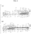
- Fig. 2 represents front views illustrating motion of a carriage of the sheet conveyance apparatus of Fig. 1
- Fig. 2(A) illustrates a state where the carriage is at a position at which the length of the sheet accumulation area is the shortest
- Fig. 2(B) illustrates a state where the carriage is at a position at which the length of the sheet accumulation area is the longest.
- the drive roller 1 has a horizontal rotary shaft 1a and four first pulleys (roller elements) 1b spaced apart from each other in the axis direction and attached to the rotary shaft 1a integrally with and rotatably about the rotary shaft 1a.
- the idle roller 2 has four second pulleys 2b (roller elements) arranged so as to be rotatable about a shaft 2a parallel to the rotary shaft 1a of the drive roller 1 and face the four first pulleys 1b, respectively.
- each endless conveyer belt 3 is stretched between the first pulley 1b of the drive roller 1 and the second pulley 2b of the idle roller 2 that are paired with each other.
- Each endless conveyer belt 3 has airflow holes 3a evenly over the entire length thereof.
- the first drive mechanism 4 has a pulley 4a fixed to one end of the rotary shaft 1a of the drive roller 1, a motor 4b whose drive shaft extends parallel to the drive roller 1, a pulley 4c fixed to the drive shaft of the motor 4b, and an endless belt 4d stretched between the pulley 4a and the pulley 4c.
- the four endless conveyer belts 3 simultaneously are rotated at a constant speed in response to the drive roller 1 being driven and rotated by the motor 4b, and the sheet S placed on the conveyer surfaces 3b of the four endless conveyer belts 3 is conveyed from the idle roller 2 side (the upstream end u of the conveyer surface 3b) to the drive roller 1 side (the downstream end w of the conveyer surface 3b).
- a carriage 8 arranged above the endless conveyer belts 3 so as to be able to reciprocate in the longitudinal direction of the endless conveyer belt 3, at least one (two in this embodiment) slide guide 9 that extends in the longitudinal direction of the endless conveyer belt 3 and to which the carriage 8 is slidably attached, and a second drive mechanism 10 that causes the carriage 8 to slide.
- the second drive mechanism 10 has a motor 10a and a pulley 10b spaced apart from each other in the longitudinal direction of the slide guide 9.
- the drive shaft of the motor 10a and the rotary shaft of the pulley 10b extend parallel to the drive roller 1 and the idle roller 2.
- a pulley 10c is fixed to the drive shaft of the motor 10a, and an endless belt 10d is stretched between the pulley 10c and the pulley 10b and extends parallel to the slide guide 9.
- the carriage 8 is fixed to the endless belt 10d.
- the carriage 8 may slide and reciprocate along the slide guide 9.
- a suction box 11 arranged between the upper and lower belt portions 3c and 3d of the four endless conveyer belts 3 so as to be able to reciprocate in the longitudinal direction of the endless conveyer belt 3 and a suction fan (intake source) 12 directly coupled to the suction box 11 and configured to generate a negative pressure inside the suction box 11.
- the suction box 11 is attached to the carriage 8. Further, the suction box 11 has intake holes 11a at positions in the upper surface above which respective endless conveyer belts 3 (the upper belt portions 3c) pass by and includes a shutter 11b therein that opens and closes the intake holes 11a.
- the shutter 11b is opened and closed at constant timings, and thereby suction through the intake holes 11a is performed at the constant timings.
- At least one (one in this embodiment) conveyance roller pair 13 extending across the conveyer surfaces 3b above the upstream end u of the conveyer surfaces 3b of the endless conveyer belts 3 and configured to take in the sheet S and feed out the sheet S onto the conveyer surfaces 3b and stopper plates 14 attached to the carriage 8 and extending across the conveyer surfaces 3b and upward from the conveyer surfaces 3b.
- the stopper plates 14 are separated into four parts in the longitudinal direction thereof, and each part of the stopper plates 14 corresponds to each endless conveyer belt 3.
- stopper plates 14 may be formed of a single stopper plate extending across the entire conveyer surfaces 3b of the four endless conveyer belts 3.
- the lower end 14a of the stopper plate 14 faces the suction box 11 and is arranged with a predetermined spacing from the conveyer surface 3b, and a region from the stopper plate 14 to the upstream end u of the conveyer surface 3b in the conveyer surface 3b forms a sheet accumulation area 15.
- the conveyance roller pair 16 is arranged at the downstream end w of the conveyer surfaces 3b and extends across the conveyer surfaces 3b.
- the conveyance roller pair 16 receives the sheet S from the downstream end w of the conveyer surfaces 3b and discharges the received sheet S to outside of the sheet conveyance apparatus.
- a discharge port of the upstream sheet processing apparatus is connected to the inlet side of the conveyance roller pair 13, and a feed port of the downstream sheet processing apparatus is connected to the outlet side of the conveyance roller pair 16.
- the position of the carriage 8, that is, of the stopper plate 14 and the suction box 11 is adjusted in accordance with the length of the sheet S to be conveyed (the length in the conveyance direction), and thereby the length of the sheet accumulation area 15 is adjusted.
- the lowermost sheet of the accumulated sheets is separated from the remaining sheets S by the suction box 11 one by one, conveyed by the endless conveyer belts 3 toward the downstream end w of the conveyer surface 3b through the spacing between the conveyer surface 3b and the stopper plate 14, and supplied to the downstream sheet processing apparatus by the conveyance roller pair 16.
- the sheet conveyance apparatus can temporarily accumulate the sheets S, which have been sequentially discharged from the upstream sheet processing apparatus, in the sheet accumulation area 15 and supply the lowermost sheet S out of the accumulated sheets S from the sheet accumulation area 15 to the downstream sheet processing apparatus one by one at timings synchronized with the processing speed of the downstream sheet processing apparatus.
- the sheet conveyance apparatus can facilitate smooth handover of the sheet S between the upstream and downstream sheet processing apparatuses.
- a mechanism to prevent contact between the accumulated lowermost sheet S and the conveyer surfaces 3b of the endless conveyer belts 3 is further provided in a region upstream of the upstream end 11c of the suction box 11 in the sheet accumulation area 15.
- the mechanism to prevent contact has five third pulleys (roller elements) 5 provided coaxially with the second pulleys 2b between adjacent second pulleys 2b of the idle roller 2 and outside the outermost second pulleys 2b and made rotatable about the shaft 2a.
- each third pulley 5 has a larger diameter than the second pulley 2b.
- the mechanism to prevent contact further has a cover sheet 17 that covers a region upstream of the suction box 11 in the sheet accumulation area 15.
- the cover sheet 17 has a width corresponding to the width of the sheet accumulation area 15 and a length that is equal to or larger than the length from the upstream end 11c of the suction box 11 to the upstream end u of the sheet accumulation area 15 when the length of the sheet accumulation area 15 is the largest.
- the mechanism to prevent contact further has two winding-type constant force plate springs 18 arranged at a fixed position under the downstream end of the endless conveyer belts 3.
- the one end 17a of the cover sheet 17 is fixed to the upstream end of the suction box 11 and extends across the sheet accumulation area 15, and the other end 17b of the cover sheet 17 extends to the winding-type constant force plate springs 18 via a part of the circumferential surface of the third pulleys 5 of the idle roller 2 and is attached to the end of each winding-type constant force plate spring 18.
- the cover sheet 17 is continually subjected to tension by the winding-type constant force plate springs 18 and continually tensed in a state of being spaced apart from the endless conveyer belts 3 even when the length of the sheet accumulation area 15 is changed. Further, even when the endless conveyer belts 3 are rotated, the cover sheet 17 is stationary in a tense state.
- any tensioner that can continually apply tension in the longitudinal direction of the cover sheet 17 can be used instead of the winding-type constant force plate springs 18.
- cover sheet 17 is arranged such that the other end 17b turns back along the circumferential surface of the third pulley 5 of the idle roller 2 and then extends along the lower side of the endless conveyer belts 3 in this embodiment, the arrangement of the cover sheet 17 is not limited to this embodiment and may be arrangement such that the other end 17b extends beyond the upstream end u parallel to the conveyer surface 3b, for example.
- the mechanism to prevent contact is provided as needed.
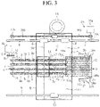
- Fig. 3 is a schematic plan view of a sheet conveyance apparatus according to another embodiment of the present invention
- Fig. 4(A) is a front view of the sheet conveyance apparatus of Fig. 3
- Fig. 4(B) is a plan view of a tensioner of the sheet conveyance apparatus of Fig. 4(A) when viewed in the X direction.
- Fig. 3 and Fig. 4 differs from the embodiment illustrated in Fig. 1 and Fig. 2 only in the configuration of the tensioner of the mechanism to prevent contact.
- the tensioner has a cover sheet winding roller 26 arranged under and parallel to a roller that is one of the drive roller 1 and the idle roller 2 which has the third pulley 5 (in this embodiment, the idle roller 2).
- the cover sheet winding roller 26 is formed of a body 26a and rotary shafts 26b and 26c projecting out of both ends of the body 26a, and a larger diameter portion 26d is provided to the rotary shaft 26b on one end side of the cover sheet winding roller 26.
- the one end 17a of the cover sheet 17 is fixed to the upstream end of the suction box 11 and extends across the sheet accumulation area 15.
- the other end 17b of the cover sheet 17 extends to the cover sheet winding roller 26 via a part of the circumferential surface of the third pulley 5 and is fixed to the circumferential surface of the cover sheet winding roller 26, and a certain length of the cover sheet 17 is wound on the cover sheet winding roller 26.
- the tensioner has a winding-type constant force plate spring 27 arranged at a fixed position in the lower side of the endless conveyer belts 3, and the fixed position is on the opposite side from the third pulley 5 with respect to the cover sheet winding roller 26 and on one end side (the rotary shaft 26b side) of the cover sheet winding roller 26.
- the winding-type constant force plate spring 27 is formed such that a winding part 27a is arranged so as to face the larger diameter portion 26d of the rotary shaft 26b and an end 27b is fixed to the circumferential surface of the larger diameter portion 26d to continually apply force to the cover sheet winding roller 26 in the winding direction of the cover sheet 17.
- the cover sheet 17 is continually subjected to tension by the tensioner (the cover sheet winding roller 26 and the winding-type constant force plate spring 27) and continually tensed in a state of being spaced apart from the endless conveyer belts 3 even when the length of the sheet accumulation area 15 is changed.
- the tensioner the cover sheet winding roller 26 and the winding-type constant force plate spring 27
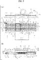
- Fig. 5 is a schematic diagram of a sheet conveyance apparatus according to another embodiment of the present invention
- Fig. 5(A) is a plan view
- Fig. 5(B) is a front view.
- Fig. 5 differs from the embodiment illustrated in Fig. 1 only in the configuration of the mechanism to prevent contact.
- the mechanism to prevent contact has third pulleys (roller elements) 19 provided coaxially with the second pulleys 2b between adjacent second pulleys 2b of the idle roller 2 and outside the outermost second pulleys 2b and made rotatable about the shaft 2a.
- each third pulley 19 has a larger diameter than the second pulley 2b.
- the mechanism to prevent contact has fourth pulleys (roller elements) 20 provided coaxially with the first pulleys 1b between adjacent first pulleys 1b of the drive roller 1 and outside the outermost first pulleys 1b and made rotatable independently of the rotary shaft 1a.
- each fourth pulley 20 has a smaller diameter than the first pulley 1b.
- the mechanism to prevent contact further has additional endless belts 21 extending parallel to the endless conveyer belt 3 stretched between the paired third and fourth pulleys 19 and 20.
- the upper surface 21a of the additional endless belt 21 has a lower friction factor than the conveyer surface 3b of the endless conveyer belt 3.
- a guide 25 to guide the additional endless belts 21 is attached to the upstream end face of the suction box 11.
- the guide 25 has a horizontal guide roller 22 extending across the conveyer surfaces 3b at a position spaced apart from the upstream end face of the suction box 11 and a guide plate 23 extending parallel to the guide roller 22 on the opposite side from the suction box 11 with respect to the guide roller 22.
- the guide plate 23 has a cross section of an inverse L-shape with round corners.
- the guide roller 22 has a vertex located at substantially the same height as the upper surface of the suction box 11, and the guide plate 23 has a top face located at substantially the same height as the vertex of the third pulleys 19 of the idle roller 2.
- each additional endless belt 21 extends to the guide plate 23 in the conveyance direction from the third pulley 19, extends downward along the guide plate 23, then extends toward the upper edge of the upstream end face of the suction box 11 along the under surface of the guide roller 22, and then extends to the fourth pulley 20 along the upper surface of the suction box 11.
- a tension roller 24 extending across the additional endless belts 21 is arranged in the middle of the lower belt portions of the additional endless belts 21.
- the tension roller 24 continually maintains the additional endless belts 21 in a tense state even when the position of the carriage 8 (the stopper plate 24 and the suction box 11) is changed and the length of the sheet accumulation area 15 is thus changed.
- each endless belt 21 is located at a higher position than the conveyer surface 3b of the endless conveyer belt 3 in a region upstream of the suction box 11 in the sheet accumulation area 15 but is located at a lower position than the conveyer surface 3b of the endless conveyer belt 3 in a region overlapping the suction box 11 in the sheet accumulation area 15 and a region downstream of the sheet accumulation area 15 on the conveyer surface 3b.
- the additional endless belts 21 protrude out of the region upstream of the suction box 11 in the sheet accumulation area 15 on the conveyer surfaces 3b of the endless conveyer belts 3, and in this region, contact between the accumulated lowermost sheet S and the endless conveyer belts 3 is prevented.
- the additional endless belts 21 are stationary even when the endless conveyer belts 3 are rotated.
Landscapes
- Engineering & Computer Science (AREA)
- Mechanical Engineering (AREA)
- Delivering By Means Of Belts And Rollers (AREA)
Abstract
Description
- The present invention relates to a sheet conveyance apparatus that conveys a sheet discharged from one sheet processing apparatus to another sheet processing apparatus, in particular, to a sheet conveyance apparatus having a function of temporarily accumulating sheets in the middle of conveyance.
- In a book binding process, two separate sheet processing apparatuses are connected to each other via a sheet conveyance apparatus, a sheet discharged from one of the sheet processing apparatuses is fed to the other sheet processing apparatus by the sheet conveyance apparatus, and this provides automated operation and increased productivity.
- In such a case, the sheet conveyance apparatus needs to feed sheets, which have been sequentially discharged from the upstream sheet processing apparatus, to the downstream sheet processing apparatus in accordance with a processing timing of the downstream sheet processing apparatus.
- In general, the processing speed of the upstream sheet processing apparatus and the processing speed of the downstream sheet processing apparatus are not the same. Thus, for example, when the upstream sheet processing apparatus has a faster processing speed than the downstream sheet processing apparatus, it is required to temporarily accumulate and store sheets in the middle of conveyance of the sheet conveyance apparatus and then convey the accumulated sheets to the downstream in accordance with the processing timing of the downstream sheet processing apparatus.
- In the conventional art, however, although there is a sheet conveyance apparatus that temporarily accumulates sheets discharged one by one from the upstream sheet processing apparatus (a printing apparatus or the like) in the middle of conveyance and, every time sheets for one volume are accumulated, conveys the sheet bundle for one volume to the downstream sheet processing apparatus (book binder) (for example, see Patent Literature 1), there has been no sheet conveyance apparatus that temporarily accumulates sheets in the middle of conveyance and can convey the accumulated sheets one by one to the downstream.
- [PTL 1]
Japanese Patent Application Laid-Open No. 2001-19261 - Accordingly, an object of the present invention is to provide a sheet conveyance apparatus that may temporarily accumulate sheets in the middle of conveyance and then convey the accumulated sheets one by one to the downstream.
- To achieve the above object, according to the present invention, provided is a sheet conveyance apparatus including: a drive roller and an idle roller extending both horizontally and parallel to each other; at least one endless conveyer belt stretched between the drive roller and the idle roller; a first drive mechanism configured to rotate the drive roller; a carriage arranged so as to reciprocate in a longitudinal direction of the endless conveyer belt above the at least one endless conveyer belt; at least one slide guide extending in the longitudinal direction of the endless conveyer belt, the carriage being slidably attached to the at least one slide guide, a second drive mechanism being configured to slide the carriage; a suction box arranged so as to reciprocate in the longitudinal direction of the endless conveyer belt between upper and lower belt portions of the at least one endless conveyer belt; and an intake source configured to generate a negative pressure inside the suction box, wherein the suction box is attached to the carriage and has at least one intake hole in a surface facing the upper belt portion, wherein a plurality of airflow holes are provided in the longitudinal direction of the at least one endless conveyer belt at positions of the at least one endless conveyer belt that pass by the at least one intake hole during rotation of the at least one endless conveyer belt, and the sheet conveyance apparatus further including: at least one conveyance roller pair extending above an upstream end of a conveyer surface of the at least one endless conveyer belt and across the conveyer surface and configured to take in a sheet and feed out the sheet onto the conveyer surface; and a stopper plate attached to the carriage and extending across the conveyer surface and upward from the conveyer surface, wherein a lower end of the stopper plate faces the suction box and is arranged with a predetermined spacing from the conveyer surface, and a region in the conveyer surface from the stopper plate to the upstream end of the conveyer surface forms a sheet accumulation area, and wherein sheets fed out from the at least one conveyance roller pair are sequentially accumulated in the sheet accumulation area when each front end of the sheets collides with the stopper plate, and the lowermost sheet of accumulated sheets is separated one by one from remaining sheets by the suction box and conveyed toward a downstream end of the conveyer surface through the spacing between the conveyer surface and the stopper plate by the at least one endless conveyer belt.
- According to a preferred embodiment of the present invention, the sheet conveyance apparatus further includes a mechanism to prevent contact between the accumulated lowermost sheet and the conveyer surface of the at least one endless conveyer belt in a region upstream of the upstream end of the suction box in the sheet accumulation area.
- According to another preferred embodiment of the present invention, the mechanism to prevent contact has a cover sheet that covers a region upstream of the suction box in the sheet accumulation area, the cover sheet has a width corresponding to a width of the sheet accumulation area and a length equal to or larger than a length from the upstream end of the suction box to an upstream end of the sheet accumulation area when a length of the sheet accumulation area is the largest, and one end of the cover sheet is fixed to the upstream end of the suction box and extends across the sheet accumulation area, and wherein the mechanism to prevent contact further has a tensioner attached to the other end of the cover sheet and configured to continually apply tension in a longitudinal direction of the cover sheet, and the cover sheet is tensed in a state where a portion of the cover sheet covering the at least one endless conveyer belt is continually spaced apart from the at least one endless conveyer belt.
- According to yet another preferred embodiment of the present invention, the at least one endless conveyer belt includes a plurality of endless conveyer belts spaced apart from each other in the width direction, wherein the drive roller has a horizontal rotary shaft, and a plurality of first roller elements axially spaced apart from each other and attached to the rotary shaft integrally with and rotatably about the rotary shaft, wherein the idle roller has a plurality of second roller elements arranged so as to be rotatable about a parallel shaft parallel to the rotary shaft of the drive roller and face the plurality of first roller elements, respectively, and each of the plurality of endless conveyer belts is stretched between the first and second roller elements paired with each other, and the rotary shaft of the drive roller is rotated by the first drive mechanism, wherein the mechanism to prevent contact further has, between the first roller elements adjacent to each other or the second roller elements adjacent to each other of a roller that is one of the drive roller and the idle roller which is located at the upstream end of the conveyer surface and outside the outermost one of the first or second roller elements, a plurality of third roller elements each provided coaxially with the first or second roller elements and rotatably independently of the rotary shaft or rotatably about the parallel shaft, and each of the third roller elements has a larger diameter than each of the first or second roller elements of interest, and wherein the tensioner includes at least one winding-type constant force plate spring arranged at a fixed position under the at least one endless conveyer belt, and the other end of the cover sheet extends to the at least one winding-type constant force plate spring via a part of circumferential surfaces of the third roller elements and is attached to an end of the at least one winding-type constant force plate spring.
- According to yet another preferred embodiment of the present invention, the at least one endless conveyer belt includes a plurality of endless conveyer belts spaced apart from each other in the width direction, wherein the drive roller has a horizontal rotary shaft, and a plurality of first roller elements axially spaced apart from each other and attached to the rotary shaft integrally with and rotatably about the rotary shaft, wherein the idle roller has a plurality of second roller elements arranged so as to be rotatable about a parallel shaft parallel to the rotary shaft of the drive roller and face the plurality of first roller elements, respectively, and each of the plurality of endless conveyer belts is stretched between the first and second roller elements paired with each other, and the rotary shaft of the drive roller is rotated by the first drive mechanism, wherein the mechanism to prevent contact further has, between the first roller elements adjacent to each other or the second roller elements adjacent to each other of a roller that is one of the drive roller and the idle roller which is located at the upstream end of the conveyer surface and outside the outermost one of the first or second roller elements, a plurality of third roller elements each provided coaxially with the first or second roller elements and rotatably independently of the rotary shaft or rotatably about the parallel shaft, and each of the third roller elements has a larger diameter than each of the first or second roller elements of interest, wherein the tensioner has a cover sheet winding roller arranged under and parallel to a roller that is one of the drive roller and the idle roller which has the third roller elements, and the other end of the cover sheet extends to the cover sheet winding roller via a part of circumferential surfaces of the third roller elements and is fixed to a circumferential surface of the cover sheet winding roller, and wherein the tensioner further has at least one winding-type constant force plate spring arranged at a fixed position under the at least one endless conveyer belt, the fixed position is on the opposite side from the third roller elements with respect to the cover sheet winding roller and on at least one end side of the cover sheet winding roller, an end of the winding-type constant force plate spring is attached to a rotary shaft of the cover sheet winding roller, and the winding-type constant force plate spring continually applies force to the cover sheet winding roller in a winding direction of the cover sheet.
- According to yet another preferred embodiment of the present invention, the at least one endless conveyer belt includes a plurality of endless conveyer belts spaced apart from each other in the width direction, wherein the drive roller has a horizontal rotary shaft, and a plurality of first roller elements axially spaced apart from each other and attached to the rotary shaft integrally with and rotatably about the rotary shaft, wherein the idle roller has a plurality of second roller elements arranged so as to be rotatable about a parallel shaft parallel to the rotary shaft and face the plurality of first roller elements, and each of the plurality of endless conveyer belts is stretched between the first and second roller elements paired with each other, and the rotary shaft of the drive roller is rotated by the first drive mechanism, wherein the mechanism to prevent contact has, between the first roller elements adjacent to each other or the second roller elements adjacent to each other of a roller that is one of the drive roller and the idle roller which is located at the upstream end of the conveyer surface and outside the outermost one of the first or second roller elements, a plurality of third roller elements each provided coaxially with the first or second roller elements and rotatably independently of the rotary shaft or rotatably about the parallel shaft, and each of the third roller elements has a larger diameter than each of the first or second roller elements of interest, wherein the mechanism to prevent contact further has, between the first roller elements adjacent to each other or the second roller elements adjacent to each other of a roller that is one of the drive roller and the idle roller which is located at the downstream end of the conveyer surface and outside the outermost one of the first or second roller elements, a plurality of fourth roller elements each provided coaxially with the first or second roller elements and rotatably independently of the rotary shaft or rotatably about the parallel shaft, and each of the fourth roller elements has a smaller diameter than each of the first or second roller elements of interest, and wherein the mechanism to prevent contact further has an additional endless belt stretched between the third and fourth roller elements paired with each other and extending parallel to the plurality of endless conveyer belts, and an upper surface of the additional endless belt has a smaller friction factor than respective conveyer surfaces of the plurality of endless conveyer belts, and the upper surface of the additional endless belt is at a higher position than the conveyer surfaces of the plurality of endless conveyer belts in a region upstream of the suction box in the sheet accumulation area and is at a lower position than the conveyer surfaces of the plurality of endless conveyer belts in a region overlapping the suction box in the sheet accumulation area and a region downstream of the sheet accumulation area on the conveyer surfaces.
- According to the present invention, even when the processing speed of the upstream sheet processing apparatus is faster than the processing speed of the downstream sheet processing apparatus, it is possible to facilitate smooth handover of sheets between the upstream and downstream sheet processing apparatuses by temporarily accumulating sheets, which have been sequentially discharged from the upstream sheet processing apparatus, in a sheet accumulation area and feeding the lowermost sheet of the accumulated sheets one by one from the sheet accumulation area to the downstream sheet processing apparatus at a timing in accordance with the processing speed of the downstream sheet processing apparatus.
- In addition, even when the length (the length in the conveyance direction) of a sheet to be processed in the upstream and downstream sheet processing apparatuses is changed, it is possible to address the change in the sheet size easily and quickly by changing the position of a carriage, that is, of a suction box and a stopper plate in accordance with the length of the sheet to adjust the length of the sheet accumulation area.
-
- [
Fig. 1 ]
Fig. 1 represents schematic diagrams of a sheet conveyance apparatus according to one embodiment of the present invention,Fig. 1(A) is a plan view, andFig. 1(B) is a front view. - [
Fig. 2 ]
Fig. 2 represents front views illustrating motion of a carriage of the sheet conveyance apparatus ofFig. 1 ,Fig. 2(A) illustrates a state where the carriage is at a position at which the length of the sheet accumulation area is the shortest, andFig. 2(B) illustrates a state where the carriage is at a position at which the length of the sheet accumulation area is the longest. - [
Fig. 3 ]
Fig. 3 is a schematic plan view of a sheet conveyance apparatus according to another embodiment of the present invention. - [
Fig. 4 ]
Fig. 4(A) is a front view of the sheet conveyance apparatus ofFig. 3 , andFig. 4(B) is a plan view of a tensioner of the sheet conveyance apparatus ofFig. 4(A) when viewed in the X direction. - [
Fig. 5 ]
Fig. 5 represents schematic diagrams of a sheet conveyance apparatus according to another embodiment of the present invention,Fig. 5(A) is a plan view, andFig. 5(B) is a front view. - The configuration of the present invention will be described below based on preferred embodiments with reference to the attached drawings.
-
Fig. 1 represents schematic diagrams of a sheet conveyance apparatus according to one embodiment of the present invention,Fig. 1(A) is a plan view, andFig. 1(B) is a front view.Fig. 2 represents front views illustrating motion of a carriage of the sheet conveyance apparatus ofFig. 1 ,Fig. 2(A) illustrates a state where the carriage is at a position at which the length of the sheet accumulation area is the shortest, andFig. 2(B) illustrates a state where the carriage is at a position at which the length of the sheet accumulation area is the longest. - With reference to
Fig. 1 , according to the present invention, there are provided adrive roller 1 and anidle roller 2 both extending horizontally and parallel to each other, at least one (four in this embodiment)endless conveyer belt 3 stretched between thedrive roller 1 and theidle roller 2, and afirst drive mechanism 4 that rotates thedrive roller 1. - The
drive roller 1 has a horizontal rotary shaft 1a and four first pulleys (roller elements) 1b spaced apart from each other in the axis direction and attached to the rotary shaft 1a integrally with and rotatably about the rotary shaft 1a. - The
idle roller 2 has foursecond pulleys 2b (roller elements) arranged so as to be rotatable about ashaft 2a parallel to the rotary shaft 1a of thedrive roller 1 and face the fourfirst pulleys 1b, respectively. - Further, each
endless conveyer belt 3 is stretched between thefirst pulley 1b of thedrive roller 1 and thesecond pulley 2b of theidle roller 2 that are paired with each other. Eachendless conveyer belt 3 hasairflow holes 3a evenly over the entire length thereof. - The
first drive mechanism 4 has apulley 4a fixed to one end of the rotary shaft 1a of thedrive roller 1, amotor 4b whose drive shaft extends parallel to thedrive roller 1, apulley 4c fixed to the drive shaft of themotor 4b, and anendless belt 4d stretched between thepulley 4a and thepulley 4c. - Further, during operation of the sheet conveyance apparatus, the four
endless conveyer belts 3 simultaneously are rotated at a constant speed in response to thedrive roller 1 being driven and rotated by themotor 4b, and the sheet S placed on theconveyer surfaces 3b of the fourendless conveyer belts 3 is conveyed from theidle roller 2 side (the upstream end u of theconveyer surface 3b) to thedrive roller 1 side (the downstream end w of theconveyer surface 3b). - According to the present invention, there are further provided a
carriage 8 arranged above theendless conveyer belts 3 so as to be able to reciprocate in the longitudinal direction of theendless conveyer belt 3, at least one (two in this embodiment)slide guide 9 that extends in the longitudinal direction of theendless conveyer belt 3 and to which thecarriage 8 is slidably attached, and asecond drive mechanism 10 that causes thecarriage 8 to slide. - The
second drive mechanism 10 has amotor 10a and apulley 10b spaced apart from each other in the longitudinal direction of theslide guide 9. The drive shaft of themotor 10a and the rotary shaft of thepulley 10b extend parallel to thedrive roller 1 and theidle roller 2. - Further, a
pulley 10c is fixed to the drive shaft of themotor 10a, and anendless belt 10d is stretched between thepulley 10c and thepulley 10b and extends parallel to theslide guide 9. Thecarriage 8 is fixed to theendless belt 10d. - Further, when the
endless belt 10d is rotated forward and backward by themotor 10a, thecarriage 8 may slide and reciprocate along theslide guide 9. - According to the present invention, there are further provided a
suction box 11 arranged between the upper andlower belt portions endless conveyer belts 3 so as to be able to reciprocate in the longitudinal direction of theendless conveyer belt 3 and a suction fan (intake source) 12 directly coupled to thesuction box 11 and configured to generate a negative pressure inside thesuction box 11. - The
suction box 11 is attached to thecarriage 8. Further, thesuction box 11 hasintake holes 11a at positions in the upper surface above which respective endless conveyer belts 3 (theupper belt portions 3c) pass by and includes ashutter 11b therein that opens and closes theintake holes 11a. - Further, during operation of the sheet conveyance apparatus, while the
suction fan 12 is continuously operated, theshutter 11b is opened and closed at constant timings, and thereby suction through theintake holes 11a is performed at the constant timings. - Further, according to the present invention, at least one (one in this embodiment)
conveyance roller pair 13 extending across theconveyer surfaces 3b above the upstream end u of theconveyer surfaces 3b of theendless conveyer belts 3 and configured to take in the sheet S and feed out the sheet S onto theconveyer surfaces 3b andstopper plates 14 attached to thecarriage 8 and extending across theconveyer surfaces 3b and upward from theconveyer surfaces 3b. - In this embodiment, the
stopper plates 14 are separated into four parts in the longitudinal direction thereof, and each part of thestopper plates 14 corresponds to eachendless conveyer belt 3. - Note that the
stopper plates 14 may be formed of a single stopper plate extending across theentire conveyer surfaces 3b of the fourendless conveyer belts 3. - The
lower end 14a of thestopper plate 14 faces thesuction box 11 and is arranged with a predetermined spacing from theconveyer surface 3b, and a region from thestopper plate 14 to the upstream end u of theconveyer surface 3b in theconveyer surface 3b forms asheet accumulation area 15. - It is possible to change the length of the
sheet accumulation area 15 within a range between the minimum length (seeFig. 2(A) ) and the maximum length (seeFig. 2(B) ) by changing the position of thecarriage 8, that is, of thestopper plate 14 and thesuction box 11. - Further, the
conveyance roller pair 16 is arranged at the downstream end w of theconveyer surfaces 3b and extends across theconveyer surfaces 3b. Theconveyance roller pair 16 receives the sheet S from the downstream end w of theconveyer surfaces 3b and discharges the received sheet S to outside of the sheet conveyance apparatus. - In the configuration described above, a discharge port of the upstream sheet processing apparatus is connected to the inlet side of the
conveyance roller pair 13, and a feed port of the downstream sheet processing apparatus is connected to the outlet side of theconveyance roller pair 16. - Further, before starting an operation of the sheet conveyance apparatus, the position of the
carriage 8, that is, of thestopper plate 14 and thesuction box 11 is adjusted in accordance with the length of the sheet S to be conveyed (the length in the conveyance direction), and thereby the length of thesheet accumulation area 15 is adjusted. - During operation of the sheet conveyance apparatus, the front ends of the sheets S taken in from the upstream sheet processing apparatus by the
conveyance roller pair 13 collide with thestopper plate 14 and thereby these sheets S are sequentially accumulated in thesheet accumulation area 15. On the other hand, the lowermost sheet of the accumulated sheets is separated from the remaining sheets S by thesuction box 11 one by one, conveyed by theendless conveyer belts 3 toward the downstream end w of theconveyer surface 3b through the spacing between theconveyer surface 3b and thestopper plate 14, and supplied to the downstream sheet processing apparatus by theconveyance roller pair 16. - In such a way, even when the processing speed of the upstream sheet processing apparatus is higher than the processing speed of the downstream sheet processing apparatus, the sheet conveyance apparatus can temporarily accumulate the sheets S, which have been sequentially discharged from the upstream sheet processing apparatus, in the
sheet accumulation area 15 and supply the lowermost sheet S out of the accumulated sheets S from thesheet accumulation area 15 to the downstream sheet processing apparatus one by one at timings synchronized with the processing speed of the downstream sheet processing apparatus. Thus, the sheet conveyance apparatus can facilitate smooth handover of the sheet S between the upstream and downstream sheet processing apparatuses. - In addition, even when the length of the sheet S to be processed in the upstream and downstream sheet processing apparatuses has been changed, it is possible to address a change in the sheet size easily and smoothly by changing the position of the
carriage 8, that is, of thesuction box 11 and thestopper plate 14 in accordance with the length of the sheet S to adjust the length of thesheet accumulation area 15. - In this embodiment, a mechanism to prevent contact between the accumulated lowermost sheet S and the conveyer surfaces 3b of the
endless conveyer belts 3 is further provided in a region upstream of theupstream end 11c of thesuction box 11 in thesheet accumulation area 15. - The mechanism to prevent contact has five third pulleys (roller elements) 5 provided coaxially with the
second pulleys 2b between adjacentsecond pulleys 2b of theidle roller 2 and outside the outermostsecond pulleys 2b and made rotatable about theshaft 2a. - Further, each
third pulley 5 has a larger diameter than thesecond pulley 2b. - The mechanism to prevent contact further has a
cover sheet 17 that covers a region upstream of thesuction box 11 in thesheet accumulation area 15. - The
cover sheet 17 has a width corresponding to the width of thesheet accumulation area 15 and a length that is equal to or larger than the length from theupstream end 11c of thesuction box 11 to the upstream end u of thesheet accumulation area 15 when the length of thesheet accumulation area 15 is the largest. - The mechanism to prevent contact further has two winding-type constant force plate springs 18 arranged at a fixed position under the downstream end of the
endless conveyer belts 3. - Further, the one
end 17a of thecover sheet 17 is fixed to the upstream end of thesuction box 11 and extends across thesheet accumulation area 15, and theother end 17b of thecover sheet 17 extends to the winding-type constant force plate springs 18 via a part of the circumferential surface of thethird pulleys 5 of theidle roller 2 and is attached to the end of each winding-type constantforce plate spring 18. - The
cover sheet 17 is continually subjected to tension by the winding-type constant force plate springs 18 and continually tensed in a state of being spaced apart from theendless conveyer belts 3 even when the length of thesheet accumulation area 15 is changed. Further, even when theendless conveyer belts 3 are rotated, thecover sheet 17 is stationary in a tense state. - In such a way, the region upstream of the
suction box 11 in thesheet accumulation area 15 in the conveyer surfaces 3b of theendless conveyer belts 3 is continually covered with thecover sheet 17. Thus, while the lowermost sheet S accumulated in thesheet accumulation area 15 is separated from the remaining sheets S by thesuction box 11 and fed out to the downstream from thesheet accumulation area 15 by theendless conveyer belts 3, it is prevented that the sheet S (standing by for being subsequently fed out) right above the sheet S being conveyed comes into contact with theendless conveyer belts 3 and is erroneously conveyed. - It is thus possible to reliably prevent occurrence of a conveyance error such as multi-feed or follow-feed of the sheet S to the downstream from the
sheet accumulation area 15. - Note that, although the
other end 17b of thecover sheet 17 is pulled by the winding-type constant force plate springs 18 in this embodiment, any tensioner that can continually apply tension in the longitudinal direction of thecover sheet 17 can be used instead of the winding-type constant force plate springs 18. - Further, although the
cover sheet 17 is arranged such that theother end 17b turns back along the circumferential surface of thethird pulley 5 of theidle roller 2 and then extends along the lower side of theendless conveyer belts 3 in this embodiment, the arrangement of thecover sheet 17 is not limited to this embodiment and may be arrangement such that theother end 17b extends beyond the upstream end u parallel to theconveyer surface 3b, for example. - The mechanism to prevent contact is provided as needed.
-
Fig. 3 is a schematic plan view of a sheet conveyance apparatus according to another embodiment of the present invention,Fig. 4(A) is a front view of the sheet conveyance apparatus ofFig. 3 , andFig. 4(B) is a plan view of a tensioner of the sheet conveyance apparatus ofFig. 4(A) when viewed in the X direction. - The embodiment of
Fig. 3 andFig. 4 differs from the embodiment illustrated inFig. 1 andFig. 2 only in the configuration of the tensioner of the mechanism to prevent contact. - Thus, in
Fig. 3 andFig. 4 , the same components as those inFig. 1 andFig. 2 are labeled with the same numerals, and the detailed description thereof will be omitted below. - In the embodiment of
Fig. 3 andFig. 4 , the tensioner has a coversheet winding roller 26 arranged under and parallel to a roller that is one of thedrive roller 1 and theidle roller 2 which has the third pulley 5 (in this embodiment, the idle roller 2). - The cover
sheet winding roller 26 is formed of abody 26a androtary shafts body 26a, and alarger diameter portion 26d is provided to therotary shaft 26b on one end side of the coversheet winding roller 26. - Further, the one
end 17a of thecover sheet 17 is fixed to the upstream end of thesuction box 11 and extends across thesheet accumulation area 15. Theother end 17b of thecover sheet 17 extends to the coversheet winding roller 26 via a part of the circumferential surface of thethird pulley 5 and is fixed to the circumferential surface of the coversheet winding roller 26, and a certain length of thecover sheet 17 is wound on the coversheet winding roller 26. - The tensioner has a winding-type constant
force plate spring 27 arranged at a fixed position in the lower side of theendless conveyer belts 3, and the fixed position is on the opposite side from thethird pulley 5 with respect to the coversheet winding roller 26 and on one end side (therotary shaft 26b side) of the coversheet winding roller 26. - The winding-type constant
force plate spring 27 is formed such that a windingpart 27a is arranged so as to face thelarger diameter portion 26d of therotary shaft 26b and anend 27b is fixed to the circumferential surface of thelarger diameter portion 26d to continually apply force to the coversheet winding roller 26 in the winding direction of thecover sheet 17. - In such a way, the
cover sheet 17 is continually subjected to tension by the tensioner (the coversheet winding roller 26 and the winding-type constant force plate spring 27) and continually tensed in a state of being spaced apart from theendless conveyer belts 3 even when the length of thesheet accumulation area 15 is changed. - Accordingly, even when the
endless conveyer belts 3 are rotated, thecover sheet 17 is stationary in a tense state. - Also in this embodiment, it is apparent that the same advantageous effect as that in the embodiment of
Fig. 1 andFig. 2 is obtained. -
Fig. 5 is a schematic diagram of a sheet conveyance apparatus according to another embodiment of the present invention,Fig. 5(A) is a plan view, andFig. 5(B) is a front view. - The embodiment of
Fig. 5 differs from the embodiment illustrated inFig. 1 only in the configuration of the mechanism to prevent contact. - Thus, in
Fig. 5 , the same components as those inFig. 1 are labeled with the same numerals, and the detailed description thereof will be omitted below. - In the embodiment of
Fig. 5 , the mechanism to prevent contact has third pulleys (roller elements) 19 provided coaxially with thesecond pulleys 2b between adjacentsecond pulleys 2b of theidle roller 2 and outside the outermostsecond pulleys 2b and made rotatable about theshaft 2a. - Further, each
third pulley 19 has a larger diameter than thesecond pulley 2b. - The mechanism to prevent contact has fourth pulleys (roller elements) 20 provided coaxially with the
first pulleys 1b between adjacentfirst pulleys 1b of thedrive roller 1 and outside the outermostfirst pulleys 1b and made rotatable independently of the rotary shaft 1a. - Further, each
fourth pulley 20 has a smaller diameter than thefirst pulley 1b. - The mechanism to prevent contact further has additional
endless belts 21 extending parallel to theendless conveyer belt 3 stretched between the paired third andfourth pulleys endless belt 21 has a lower friction factor than theconveyer surface 3b of theendless conveyer belt 3. - Furthermore, a
guide 25 to guide the additionalendless belts 21 is attached to the upstream end face of thesuction box 11. Theguide 25 has ahorizontal guide roller 22 extending across the conveyer surfaces 3b at a position spaced apart from the upstream end face of thesuction box 11 and aguide plate 23 extending parallel to theguide roller 22 on the opposite side from thesuction box 11 with respect to theguide roller 22. Theguide plate 23 has a cross section of an inverse L-shape with round corners. - The
guide roller 22 has a vertex located at substantially the same height as the upper surface of thesuction box 11, and theguide plate 23 has a top face located at substantially the same height as the vertex of thethird pulleys 19 of theidle roller 2. - Further, the upper belt portion of each additional
endless belt 21 extends to theguide plate 23 in the conveyance direction from thethird pulley 19, extends downward along theguide plate 23, then extends toward the upper edge of the upstream end face of thesuction box 11 along the under surface of theguide roller 22, and then extends to thefourth pulley 20 along the upper surface of thesuction box 11. - Furthermore, a
tension roller 24 extending across the additionalendless belts 21 is arranged in the middle of the lower belt portions of the additionalendless belts 21. Thetension roller 24 continually maintains the additionalendless belts 21 in a tense state even when the position of the carriage 8 (thestopper plate 24 and the suction box 11) is changed and the length of thesheet accumulation area 15 is thus changed. - In such a way, while the upper surface of each
endless belt 21 is located at a higher position than theconveyer surface 3b of theendless conveyer belt 3 in a region upstream of thesuction box 11 in thesheet accumulation area 15 but is located at a lower position than theconveyer surface 3b of theendless conveyer belt 3 in a region overlapping thesuction box 11 in thesheet accumulation area 15 and a region downstream of thesheet accumulation area 15 on theconveyer surface 3b. - According to this embodiment, the additional
endless belts 21 protrude out of the region upstream of thesuction box 11 in thesheet accumulation area 15 on the conveyer surfaces 3b of theendless conveyer belts 3, and in this region, contact between the accumulated lowermost sheet S and theendless conveyer belts 3 is prevented. - Furthermore, the additional
endless belts 21 are stationary even when theendless conveyer belts 3 are rotated. - Thus, while the lowermost sheet S accumulated in the
sheet accumulation area 15 is separated from the remaining sheets S by thesuction box 11 and fed out to the downstream from thesheet accumulation area 15 by theendless conveyer belts 3, it is prevented that the sheet S (standing by for being subsequently fed out) right above the sheet S being conveyed comes into contact with theendless conveyer belts 3 and is erroneously conveyed. - Although the preferred embodiments of the present invention have been described above, the configuration of the present invention is not limited to the embodiments described above, and it is apparent that those skilled in the art may devise various modified examples within the scope of the configuration described in the appended claims.
-
- 1 drive roller
- 1a rotary shaft
- 1b first pulley (roller element)
- 2 idle roller
- 2a shaft
- 2b second pulley (roller element)
- 3 endless conveyer belt
- 3a airflow hole
- 3b conveyer surface
- 3c upper belt portion
- 3d lower belt portion
- 4 first drive mechanism
- 4a pulley
- 4b motor
- 4c pulley
- 4d endless belt
- 5 third pulley (roller element)
- 8 carriage
- 9 slide guide
- 10 second drive mechanism
- 10a motor
- 10b pulley
- 10c pulley
- 10d endless belt
- 11 suction box
- 11a intake hole
- 11b shutter
- 11c upstream end
- 12 suction fan (intake source)
- 13 conveyance roller pair
- 14 stopper plate
- 14a lower end
- 15 sheet accumulation area
- 16 conveyance roller pair
- 17 cover sheet
- 17a one end
- 17b the other end
- 18 winding-type constant force plate spring
- 19 third pulley (roller element)
- 20 fourth pulley (roller element)
- 21 additional endless belt
- 21a upper surface
- 22 guide roller
- 23 guide plate
- 24 tension roller
- 25 guide
- 26 cover sheet winding roller
- 26a body
- 26b, 26c rotary shaft
- 26d larger diameter portion
- 27 winding-type constant force plate spring
- 27a winding part
- 27b end
- S sheet
- u upstream end of conveyer surfaces
- w downstream end of conveyer surfaces
Claims (6)
- A sheet conveyance apparatus comprising:a drive roller and an idle roller extending both horizontally and parallel to each other;at least one endless conveyer belt stretched between the drive roller and the idle roller;a first drive mechanism configured to rotate the drive roller;a carriage arranged so as to reciprocate in a longitudinal direction of the endless conveyer belt above the at least one endless conveyer belt;at least one slide guide extending in the longitudinal direction of the endless conveyer belt, the carriage being slidably attached to the at least one slide guide;a second drive mechanism being configured to slide the carriage;a suction box arranged so as to reciprocate in the longitudinal direction of the endless conveyer belt between upper and lower belt portions of the at least one endless conveyer belt; andan intake source configured to generate a negative pressure inside the suction box, wherein the suction box is attached to the carriage and has at least one intake hole in a surface facing the upper belt portion, whereina plurality of airflow holes are provided in the longitudinal direction of the at least one endless conveyer belt at positions of the at least one endless conveyer belt that pass by the at least one intake hole during rotation of the at least one endless conveyer belt, andthe sheet conveyance apparatus further comprising:at least one conveyance roller pair extending above an upstream end of a conveyer surface of the at least one endless conveyer belt and across the conveyer surface and configured to take in a sheet and feed out the sheet onto the conveyer surface; anda stopper plate attached to the carriage and extending across the conveyer surface and upward from the conveyer surface, whereina lower end of the stopper plate faces the suction box and is arranged with a predetermined spacing from the conveyer surface, and a region in the conveyer surface from the stopper plate to the upstream end of the conveyer surface forms a sheet accumulation area, and whereinsheets fed out from the at least one conveyance roller pair are sequentially accumulated in the sheet accumulation area when each front end of the sheets collides with the stopper plate, and the lowermost sheet of accumulated sheets is separated one by one from remaining sheets by the suction box and conveyed toward a downstream end of the conveyer surface through the spacing between the conveyer surface and the stopper plate by the at least one endless conveyer belt.
- The sheet conveyance apparatus according to claim 1, further comprising: a mechanism to prevent contact between the accumulated lowermost sheet and the conveyer surface of the at least one endless conveyer belt in a region upstream of the upstream end of the suction box in the sheet accumulation area.
- The sheet conveyance apparatus according to claim 2, the mechanism to prevent contact has a cover sheet that covers a region upstream of the suction box in the sheet accumulation area, whereinthe cover sheet has a width corresponding to a width of the sheet accumulation area and a length equal to or larger than a length from the upstream end of the suction box to an upstream end of the sheet accumulation area when a length of the sheet accumulation area is the largest, andone end of the cover sheet is fixed to the upstream end of the suction box and extends across the sheet accumulation area, and whereinthe mechanism to prevent contact further has a tensioner attached to the other end of the cover sheet and configured to continually apply tension in a longitudinal direction of the cover sheet, andthe cover sheet is tensed in a state where a portion of the cover sheet covering the at least one endless conveyer belt is continually spaced apart from the at least one endless conveyer belt.
- The sheet conveyance apparatus according to claim 3, wherein the at least one endless conveyer belt includes a plurality of endless conveyer belts spaced apart from each other in the width direction, whereinthe drive roller hasa horizontal rotary shaft, anda plurality of first roller elements axially spaced apart from each other and attached to the rotary shaft integrally with and rotatably about the rotary shaft, whereinthe idle roller hasa plurality of second roller elements arranged so as to be rotatable about a parallel shaft parallel to the rotary shaft of the drive roller and face the plurality of first roller elements, respectively, andeach of the plurality of endless conveyer belts is stretched between the first and second roller elements paired with each other, and the rotary shaft of the drive roller is rotated by the first drive mechanism, wherein the mechanism to prevent contact further has, between the first roller elements adjacent to each other or the second roller elements adjacent to each other of a roller that is one of the drive roller and the idle roller which is located at the upstream end of the conveyer surface and outside the outermost one of the first or second roller elements, a plurality of third roller elements each provided coaxially with the first or second roller elements and rotatably independently of the rotary shaft or rotatably about the parallel shaft, and each of the third roller elements has a larger diameter than each of the first or second roller elements of interest, and whereinthe tensioner includes at least one winding-type constant force plate spring arranged at a fixed position under the at least one endless conveyer belt, andthe other end of the cover sheet extends to the at least one winding-type constant force plate spring via a part of circumferential surfaces of the third roller elements and is attached to an end of the at least one winding-type constant force plate spring.
- The sheet conveyance apparatus according to claim 3, whereinthe at least one endless conveyer belt includes a plurality of endless conveyer belts spaced apart from each other in the width direction, whereinthe drive roller hasa horizontal rotary shaft, anda plurality of first roller elements axially spaced apart from each other and attached to the rotary shaft integrally with and rotatably about the rotary shaft, whereinthe idle roller has a plurality of second roller elements arranged so as to be rotatable about a parallel shaft parallel to the rotary shaft of the drive roller and face the plurality of first roller elements, respectively, andeach of the plurality of endless conveyer belts is stretched between the first and second roller elements paired with each other, and the rotary shaft of the drive roller is rotated by the first drive mechanism, whereinthe mechanism to prevent contact further has, between the first roller elements adjacent to each other or the second roller elements adjacent to each other of a roller that is one of the drive roller and the idle roller which is located at the upstream end of the conveyer surface and outside the outermost one of the first or second roller elements, a plurality of third roller elements each provided coaxially with the first or second roller elements and rotatably independently of the rotary shaft or rotatably about the parallel shaft, and each of the third roller elements has a larger diameter than each of the first or second roller elements of interest, whereinthe tensioner has a cover sheet winding roller arranged under and parallel to a roller that is one of the drive roller and the idle roller which has the third roller elements, andthe other end of the cover sheet extends to the cover sheet winding roller via a part of circumferential surfaces of the third roller elements and is fixed to a circumferential surface of the cover sheet winding roller, and whereinthe tensioner further has at least one winding-type constant force plate spring arranged at a fixed position under the at least one endless conveyer belt, the fixed position is on the opposite side from the third roller elements with respect to the cover sheet winding roller and on at least one end side of the cover sheet winding roller, an end of the winding-type constant force plate spring is attached to a rotary shaft of the cover sheet winding roller, and the winding-type constant force plate spring continually applies force to the cover sheet winding roller in a winding direction of the cover sheet.
- The sheet conveyance apparatus according to claim 2, whereinthe at least one endless conveyer belt includes a plurality of endless conveyer belts spaced apart from each other in the width direction,whereinthe drive roller hasa horizontal rotary shaft, anda plurality of first roller elements axially spaced apart from each other and attached to the rotary shaft integrally with and rotatably about the rotary shaft, whereinthe idle roller has a plurality of second roller elements arranged so as to be rotatable about a parallel shaft parallel to the rotary shaft and face the plurality of first roller elements, and each of the plurality of endless conveyer belts is stretched between the first and second roller elements paired with each other, and the rotary shaft of the drive roller is rotated by the first drive mechanism, whereinthe mechanism to prevent contact has, between the first roller elements adjacent to each other or the second roller elements adjacent to each other of a roller that is one of the drive roller and the idle roller which is located at the upstream end of the conveyer surface and outside the outermost one of the first or second roller elements, a plurality of third roller elements each provided coaxially with the first or second roller elements and rotatably independently of the rotary shaft or rotatably about the parallel shaft, and each of the third roller elements has a larger diameter than each of the first or second roller elements of interest,whereinthe mechanism to prevent contact further has, between the first roller elements adjacent to each other or the second roller elements adjacent to each other of a roller that is one of the drive roller and the idle roller which is located at the downstream end of the conveyer surface and outside the outermost one of the first or second roller elements, a plurality of fourth roller elements each provided coaxially with the first or second roller elements and rotatably independently of the rotary shaft or rotatably about the parallel shaft, and each of the fourth roller elements has a smaller diameter than each of the first or second roller elements of interest, and whereinthe mechanism to prevent contact further has an additional endless belt stretched between the third and fourth roller elements paired with each other and extending parallel to the plurality of endless conveyer belts,andan upper surface of the additional endless belt has a smaller friction factor than respective conveyer surfaces of the plurality of endless conveyer belts, and the upper surface of the additional endless belt is at a higher position than the conveyer surfaces of the plurality of endless conveyer belts in a region upstream of the suction box in the sheet accumulation area and is at a lower position than the conveyer surfaces of the plurality of endless conveyer belts in a region overlapping the suction box in the sheet accumulation area and a region downstream of the sheet accumulation area on the conveyer surfaces.
Applications Claiming Priority (2)
| Application Number | Priority Date | Filing Date | Title |
|---|---|---|---|
| JP2019185322 | 2019-10-08 | ||
| PCT/JP2020/028475 WO2021070450A1 (en) | 2019-10-08 | 2020-07-22 | Paper conveyance device |
Publications (3)
| Publication Number | Publication Date |
|---|---|
| EP4043375A1 true EP4043375A1 (en) | 2022-08-17 |
| EP4043375A4 EP4043375A4 (en) | 2023-10-18 |
| EP4043375B1 EP4043375B1 (en) | 2024-11-06 |
Family
ID=75437095
Family Applications (1)
| Application Number | Title | Priority Date | Filing Date |
|---|---|---|---|
| EP20875080.2A Active EP4043375B1 (en) | 2019-10-08 | 2020-07-22 | Paper conveyance device |
Country Status (5)
| Country | Link |
|---|---|
| US (1) | US11999583B2 (en) |
| EP (1) | EP4043375B1 (en) |
| JP (1) | JP7356182B2 (en) |
| CN (1) | CN114585577B (en) |
| WO (1) | WO2021070450A1 (en) |
Cited By (1)
| Publication number | Priority date | Publication date | Assignee | Title |
|---|---|---|---|---|
| EP3967638B1 (en) * | 2020-09-08 | 2024-11-06 | Horizon Inc. | Sheet conveyance apparatus, corresponding storage medium storing a control program, and control method of a sheet conveyance apparatus |
Family Cites Families (18)
| Publication number | Priority date | Publication date | Assignee | Title |
|---|---|---|---|---|
| US4219191A (en) * | 1979-01-08 | 1980-08-26 | Pitney Bowes Inc. | Document feeding apparatus |
| FR2476615A1 (en) | 1980-02-22 | 1981-08-28 | Martin Sa | FEEDING DEVICE IN SHEETS OF A PROCESSING MACHINE |
| US4382593A (en) * | 1980-08-04 | 1983-05-10 | International Business Machines Corporation | Vacuum document feeder |
| JPS5772532A (en) * | 1980-10-17 | 1982-05-06 | Ricoh Co Ltd | Suction head |
| JP2533957B2 (en) | 1990-03-20 | 1996-09-11 | シャープ株式会社 | Sheet feeding device with double feed prevention function |
| US5116040A (en) | 1990-04-06 | 1992-05-26 | De La Rue Giori S.A. | Sheet-feeder |
| JP2508544Y2 (en) * | 1991-02-19 | 1996-08-28 | 三菱重工業株式会社 | Paperboard feeder |
| JPH0840582A (en) * | 1994-07-29 | 1996-02-13 | Canon Inc | Sheet feeding device and image forming device provided with this sheet feeding device |
| US5836582A (en) | 1994-04-04 | 1998-11-17 | Canon Kabushiki Kaisha | Sheet feeding device with air injectors for separating sheets |
| US5954325A (en) * | 1996-06-04 | 1999-09-21 | Mita Industrial Co., Ltd. | Automatic document feeder |
| JP4169872B2 (en) | 1999-07-13 | 2008-10-22 | ホリゾン・インターナショナル株式会社 | Paper transport device |
| JP4105039B2 (en) | 2003-06-03 | 2008-06-18 | 松下電器産業株式会社 | Evaluation method of electrostatic damage |
| US8919812B2 (en) | 2010-02-18 | 2014-12-30 | Trw Automotive Safety Systems Gmbh | Steering wheel having an air bag module |
| JP4886075B1 (en) | 2011-01-31 | 2012-02-29 | 江沢事務器株式会社 | Cut paper feeding device |
| JP5772532B2 (en) | 2011-11-16 | 2015-09-02 | 富士通株式会社 | Amplifier circuit and light receiving circuit |
| CN105173797B (en) | 2015-10-16 | 2017-08-22 | 江南大学 | Full-automatic corrugation is to mounting machine |
| JP2018002368A (en) | 2016-06-30 | 2018-01-11 | 株式会社沖データ | Medium supply device |
| CN109110527A (en) | 2018-10-19 | 2019-01-01 | 湖南精正设备制造有限公司 | A kind of automation paper feeding machine being driven using negative-pressure adsorption |
-
2020
- 2020-07-22 CN CN202080070660.0A patent/CN114585577B/en active Active
- 2020-07-22 JP JP2021550374A patent/JP7356182B2/en active Active
- 2020-07-22 WO PCT/JP2020/028475 patent/WO2021070450A1/en active Application Filing
- 2020-07-22 EP EP20875080.2A patent/EP4043375B1/en active Active
- 2020-07-22 US US17/766,974 patent/US11999583B2/en active Active
Cited By (1)
| Publication number | Priority date | Publication date | Assignee | Title |
|---|---|---|---|---|
| EP3967638B1 (en) * | 2020-09-08 | 2024-11-06 | Horizon Inc. | Sheet conveyance apparatus, corresponding storage medium storing a control program, and control method of a sheet conveyance apparatus |
Also Published As
| Publication number | Publication date |
|---|---|
| EP4043375A4 (en) | 2023-10-18 |
| JPWO2021070450A1 (en) | 2021-04-15 |
| US11999583B2 (en) | 2024-06-04 |
| US20240076152A1 (en) | 2024-03-07 |
| JP7356182B2 (en) | 2023-10-04 |
| CN114585577A (en) | 2022-06-03 |
| EP4043375B1 (en) | 2024-11-06 |
| CN114585577B (en) | 2023-10-27 |
| WO2021070450A1 (en) | 2021-04-15 |
Similar Documents
| Publication | Publication Date | Title |
|---|---|---|
| US9988231B2 (en) | Sheet conveying apparatus and image forming system including the same | |
| US8634751B2 (en) | Image forming apparatus | |
| JP2017001788A (en) | Sheet processing device | |
| CN110342322B (en) | Post-processing device | |
| JP5288514B2 (en) | Paper folding device | |
| JP5246637B2 (en) | Paper reversing device | |
| US11999583B2 (en) | Sheet conveyance apparatus | |
| US8715149B2 (en) | Sheet post-processing apparatus and image forming apparatus | |
| JPH09118465A (en) | Photosensitive material arranging device | |
| US11667485B2 (en) | Sheet conveyance apparatus, control method of the same, and storage medium storing control program of the same | |
| JP6532131B2 (en) | Sheet processing apparatus and image forming system | |
| EP3964462B1 (en) | Sheet feeding apparatus, and control method of the same | |
| US10099886B2 (en) | Sheet processing apparatus and sheet discharge method | |
| JPS59102761A (en) | Paper handling device | |
| JP6487653B2 (en) | Sheet stacking device | |
| JP7186566B2 (en) | Sheet bundle conveying unit and post-processing device | |
| US6241236B1 (en) | Automated sheet delivery to selected paths using reversible crenellated roller | |
| WO2017195293A1 (en) | Paper feeder, paper processing device, and paper feeding method | |
| CN106882632B (en) | Paper transport device | |
| JP3669570B2 (en) | Paper post-processing device | |
| WO2010047376A1 (en) | Paper discharge device for printer and operating method therefor | |
| JP4199648B2 (en) | Chopper equipment | |
| JP2017200848A (en) | Paper feeder and bookbinding system | |
| JP2025013379A (en) | Processing Equipment | |
| JP2004099262A (en) | Sheet discharging mechanism and sheet processing device |
Legal Events
| Date | Code | Title | Description |
|---|---|---|---|
| STAA | Information on the status of an ep patent application or granted ep patent |
Free format text: STATUS: THE INTERNATIONAL PUBLICATION HAS BEEN MADE |
|
| PUAI | Public reference made under article 153(3) epc to a published international application that has entered the european phase |
Free format text: ORIGINAL CODE: 0009012 |
|
| STAA | Information on the status of an ep patent application or granted ep patent |
Free format text: STATUS: REQUEST FOR EXAMINATION WAS MADE |
|
| 17P | Request for examination filed |
Effective date: 20220406 |
|
| AK | Designated contracting states |
Kind code of ref document: A1 Designated state(s): AL AT BE BG CH CY CZ DE DK EE ES FI FR GB GR HR HU IE IS IT LI LT LU LV MC MK MT NL NO PL PT RO RS SE SI SK SM TR |
|
| DAV | Request for validation of the european patent (deleted) | ||
| DAX | Request for extension of the european patent (deleted) | ||
| REG | Reference to a national code |
Ref country code: DE Ref legal event code: R079 Ref document number: 602020041056 Country of ref document: DE Free format text: PREVIOUS MAIN CLASS: B65H0031300000 Ipc: B65H0003120000 Ref legal event code: R079 Free format text: PREVIOUS MAIN CLASS: B65H0031300000 |
|
| A4 | Supplementary search report drawn up and despatched |
Effective date: 20230919 |
|
| RIC1 | Information provided on ipc code assigned before grant |
Ipc: B65H 5/22 20060101ALI20230913BHEP Ipc: B65H 1/30 20060101ALI20230913BHEP Ipc: B65H 31/20 20060101ALI20230913BHEP Ipc: B65H 31/02 20060101ALI20230913BHEP Ipc: B65H 83/02 20060101ALI20230913BHEP Ipc: B65H 3/12 20060101AFI20230913BHEP |
|
| GRAP | Despatch of communication of intention to grant a patent |
Free format text: ORIGINAL CODE: EPIDOSNIGR1 |
|
| STAA | Information on the status of an ep patent application or granted ep patent |
Free format text: STATUS: GRANT OF PATENT IS INTENDED |
|
| INTG | Intention to grant announced |
Effective date: 20240627 |
|
| RIN1 | Information on inventor provided before grant (corrected) |
Inventor name: NAMBU, HIROMASA Inventor name: YACHI, TOMONORI Inventor name: AOKI, EIJI |
|
| GRAS | Grant fee paid |
Free format text: ORIGINAL CODE: EPIDOSNIGR3 |
|
| GRAA | (expected) grant |
Free format text: ORIGINAL CODE: 0009210 |
|
| STAA | Information on the status of an ep patent application or granted ep patent |
Free format text: STATUS: THE PATENT HAS BEEN GRANTED |
|
| AK | Designated contracting states |
Kind code of ref document: B1 Designated state(s): AL AT BE BG CH CY CZ DE DK EE ES FI FR GB GR HR HU IE IS IT LI LT LU LV MC MK MT NL NO PL PT RO RS SE SI SK SM TR |
|
| REG | Reference to a national code |
Ref country code: GB Ref legal event code: FG4D |
|
| REG | Reference to a national code |
Ref country code: CH Ref legal event code: EP |
|
| REG | Reference to a national code |
Ref country code: DE Ref legal event code: R096 Ref document number: 602020041056 Country of ref document: DE |
|
| REG | Reference to a national code |
Ref country code: IE Ref legal event code: FG4D |