EP4043338B1 - Klappflügelscharnier, flugzeug und verfahren dafür - Google Patents
Klappflügelscharnier, flugzeug und verfahren dafür Download PDFInfo
- Publication number
- EP4043338B1 EP4043338B1 EP22166033.5A EP22166033A EP4043338B1 EP 4043338 B1 EP4043338 B1 EP 4043338B1 EP 22166033 A EP22166033 A EP 22166033A EP 4043338 B1 EP4043338 B1 EP 4043338B1
- Authority
- EP
- European Patent Office
- Prior art keywords
- spline
- hinge pin
- hinge
- input fitting
- wing portion
- Prior art date
- Legal status (The legal status is an assumption and is not a legal conclusion. Google has not performed a legal analysis and makes no representation as to the accuracy of the status listed.)
- Active
Links
Images








Classifications
-
- B—PERFORMING OPERATIONS; TRANSPORTING
- B64—AIRCRAFT; AVIATION; COSMONAUTICS
- B64C—AEROPLANES; HELICOPTERS
- B64C13/00—Control systems or transmitting systems for actuating flying-control surfaces, lift-increasing flaps, air brakes, or spoilers
- B64C13/24—Transmitting means
- B64C13/26—Transmitting means without power amplification or where power amplification is irrelevant
- B64C13/28—Transmitting means without power amplification or where power amplification is irrelevant mechanical
- B64C13/34—Transmitting means without power amplification or where power amplification is irrelevant mechanical using toothed gearing
-
- B—PERFORMING OPERATIONS; TRANSPORTING
- B64—AIRCRAFT; AVIATION; COSMONAUTICS
- B64C—AEROPLANES; HELICOPTERS
- B64C3/00—Wings
- B64C3/38—Adjustment of complete wings or parts thereof
- B64C3/42—Adjusting about chordwise axes
-
- B—PERFORMING OPERATIONS; TRANSPORTING
- B64—AIRCRAFT; AVIATION; COSMONAUTICS
- B64C—AEROPLANES; HELICOPTERS
- B64C3/00—Wings
- B64C3/38—Adjustment of complete wings or parts thereof
- B64C3/56—Folding or collapsing to reduce overall dimensions of aircraft
-
- B—PERFORMING OPERATIONS; TRANSPORTING
- B64—AIRCRAFT; AVIATION; COSMONAUTICS
- B64F—GROUND OR AIRCRAFT-CARRIER-DECK INSTALLATIONS SPECIALLY ADAPTED FOR USE IN CONNECTION WITH AIRCRAFT; DESIGNING, MANUFACTURING, ASSEMBLING, CLEANING, MAINTAINING OR REPAIRING AIRCRAFT, NOT OTHERWISE PROVIDED FOR; HANDLING, TRANSPORTING, TESTING OR INSPECTING AIRCRAFT COMPONENTS, NOT OTHERWISE PROVIDED FOR
- B64F5/00—Designing, manufacturing, assembling, cleaning, maintaining or repairing aircraft, not otherwise provided for; Handling, transporting, testing or inspecting aircraft components, not otherwise provided for
Definitions
- This disclosure generally relates to folding wings for aircraft, and more particularly to folding wing hinges.
- long span wings are desirable for commercial aircraft to increase aerodynamic efficiency when compared to wings having a shorter span. Increased aerodynamic efficiency reduces fuels consumption and may lead to reduced aircraft operating costs.
- the wingspan of an aircraft may be limited based on limits and/or regulations imposed by the International Civil Aviation Organization (ICAO), and/or based on physical infrastructure limitations of airports (e.g., the sizes of runways, taxiways, gate areas, hangars, etc.).
- Foldable wings may be employed to reduce the wingspan of an aircraft when the aircraft is not in flight (e.g., when the aircraft is taxiing, parked, and/or stored).
- Such designs commonly include a foldable outboard section (e.g., a folding wing portion) of the wing that is hinged and/or rotatably coupled to an inboard section (e.g. a fixed wing portion) of the wing.
- the hinged and/or rotatably coupling enables movement of the foldable outboard section relative to the fixed inboard section between an unfolded position (e.g., a flight position) and a folded position (e.g. a stowed position).
- the foldable outboard section may be moved from the folded position to the unfolded position prior to takeoff of the aircraft to increase the wingspan of the aircraft.
- the foldable outboard section may conversely be moved from the unfolded position subsequent to landing of the aircraft to decrease the wingspan of the aircraft.
- US5558299 A in accordance with its abstract, states a wing fold assembly for use in aircraft which provides relative rotational movement of a first wing tip about a second fixed wing including a plurality of wing tip flanges, and a plurality of fixed wing flanges wherein all of said flanges are rotatably mounted to a central shaft and wherein the improvement comprises means for selectively interlocking said wing tip flanges in relation to said fixed wing flanges to thereby lock said wing tip in position relative said fixed wing in either of a folded or faired position.
- a folding wing hinge for a wing having a fixed wing portion and a folding wing portion
- the folding wing hinge comprising: a hinge pin including a hinge pin spline and having a first longitudinal axis; an input fitting coupled to one of the fixed wing portion and the folding wing portion, the input fitting including an input fitting spline and a second longitudinal axis; and a spline coupling member configured to couple with the hinge pin spline and the input fitting spline so that the first longitudinal axis is moveable relative to the second longitudinal axis by a first predetermined amount of movement; wherein the hinge pin spline is an external spline having teeth with a crowned tooth surface and the spline coupling member includes a first mating spline portion having an internal straight-sided spline configured to couple with the hinge pin spline; and wherein one of: a) the input fitting spline is an external spline having teeth with a
- the folding wing hinge may further comprise: at least one hinge pin bushing coupled to at least one of the fixed wing portion and the folding wing portion, the at least one hinge pin bushing having a third longitudinal axis; wherein the hinge pin extends through the at least one hinge pin bushing; and wherein the first longitudinal axis moves relative to the third longitudinal axis by a second predetermined amount of movement, the second predetermined amount of movement being less than the first predetermined amount of movement so that flight loads between the fixed wing portion and the folding wing portion are isolated or substantially isolated to a load path that passes through the at least one hinge pin bushing.
- the input fitting may be coupled to the one of the fixed wing portion and the folding wing portion with a coupling that effects relative movement between the input fitting and the one of the fixed wing portion and the folding wing portion so that flight loads between the fixed wing portion and the folding wing portion are isolated or substantially isolated to a load path that passes through at least one hinge pin bushing coupled to at least one of the fixed wing portion and the folding wing portion, wherein the hinge pin extends through the at least one hinge pin bushing.
- the folding wing hinge may further comprise: at least one hinge pin bushing coupled to at least one of the fixed wing portion and the folding wing portion, the at least one hinge pin bushing having a third longitudinal axis; and wherein the hinge pin extends through the at least one hinge pin bushing, and the input fitting includes a flanged end and a free end, the flanged end and the free end being separated by a longitudinal length that effects deflection of the free end, under flight loads, relative to the flanged end so that the first longitudinal axis of the hinge pin moves relative to the third longitudinal axis to isolate or substantially isolate flight loads between the fixed wing portion and the folding wing portion to a load path that passes through the at least one hinge pin bushing.
- the respective crowned tooth surfaces of the hinge pin spline and the input fitting spline may have a radius of: between 38 inches (97 cm) and 48 inches (122 cm); or between about 38 inches (about 97 cm) and about 48 inches (about 122 cm).
- the crowned tooth surface of the teeth of the second mating spline portion may have a radius of: between 38 inches (97 cm) and 48 inches (122 cm); or between about 38 inches (about 97 cm) and about 48 inches (about 122 cm).
- the crowned tooth surface of the teeth of the hinge pin spline may have a radius of: between 38 inches (97 cm) and 48 inches (122 cm); or between about 38 inches (about 97 cm) and about 48 inches (about 122 cm).
- an aircraft comprising: a wing having a fixed wing portion and a folding wing portion; and the folding wing hinge described above.
- the first longitudinal axis may be parallel or substantially parallel with a fuselage of the aircraft.
- the first longitudinal axis of the hinge pin may be perpendicular or substantially perpendicular to at least one spar of the fixed wing portion.
- a method for substantially isolating flight loads in a folding wing hinge comprising: providing an input fitting that is coupled to one of a fixed wing portion and a folding wing portion of a wing, wherein the input fitting includes an input fitting spline coupled with a hinge pin spline of a hinge pin; effecting relative movement between a first longitudinal axis of the hinge pin and a second longitudinal axis of the input fitting with a spline coupling member configured to couple with the hinge pin spline and the input fitting spline so that the first longitudinal axis moves relative to the second longitudinal axis by a first predetermined amount of movement; effecting relative movement between the first longitudinal axis of the hinge pin and the second longitudinal axis of the input fitting wherein the hinge pin spline is an external spline having teeth with a crowned tooth surface and the spline coupling member includes a first mating spline portion having an internal straight-sided spline; and
- the method may further comprise isolating or substantially isolating flight loads between the fixed wing portion and the folding wing portion to a load path that passes through at least one hinge pin bushing coupled to at least one of the fixed wing portion and the folding wing portion; and wherein the at least one hinge pin bushing has a third longitudinal axis, and the hinge pin extends through the at least one hinge pin bushing; and wherein the first longitudinal axis of the hinge pin moves relative to the third longitudinal axis by a second predetermined amount of movement, the second predetermined amount of movement being less than the first predetermined amount of movement.
- the method may further comprise effecting relative movement between the input fitting and the one of the fixed wing portion and the folding wing portion so that flight loads between the fixed wing portion and the folding wing portion are isolated or substantially isolated to a load path that passes through at least one hinge pin bushing coupled to at least one of the fixed wing portion and the folding wing portion, where the hinge pin extends through the at least one hinge pin bushing.
- the method may further comprise effecting deflection of a free end of the input fitting relative to a flanged end of the input fitting with a longitudinal length of the input fitting separating the free end from the flanged end so that the first longitudinal axis of the hinge pin moves relative to a third longitudinal axis of at least one hinge pin bushing coupled to at least one of the fixed wing portion and the folding wing portion to isolate or substantially isolate flight loads between the fixed wing portion and the folding wing portion to a load path that passes through the at least one hinge pin bushing.
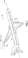
- the aircraft 100 includes a wing 102 having a folding wing portion 202 rotatably coupled to a fixed wing portion 204 by a folding wing hinge 210.
- the folding wing hinge 210 includes one or more hinge pins 600, 601, 602 installed along a hinge axis 206.
- the folding wing hinge 210 includes three hinge pins 600, 601, 602 but in other examples the folding wing hinge 210 may have more or less than three hinge pins.
- Each of the hinge pins 600, 601, 602 transfer flight loads 720 (see Fig. 7A ) from the folding wing portion 202 to the fixed wing portion 204.
- At least one of the hinge pins reacts or transfers torsional loads 750 (see Fig. 7B ) associated with folding and unfolding of the folding wing portion 202 relative to the fixed wing portion 204.
- the folding wing hinge 210 may isolate or substantially isolate the flight loads 720 (see Fig. 7A ) transferred between the folding wing portion 202 and a fixed wing portion 204 of the wing 102 from torsional loads 750 (see Fig. 7B ) associated with folding and unfolding the folding wing portion 202 relative to the fixed wing portion 204.
- Examples of the present disclosure may provide for a single hinge pin 600 that reacts or transfers both the flight loads 720 and the torsional loads 750 without a decrease in service life of the hinge pin 600 or substantially without a decrease in service life of the hinge pin 600.
- the aircraft 100 is illustrated as a commercial passenger aircraft but in other examples the aircraft 100 may be any suitable aircraft including general aviation aircraft, military aircraft, flying automobiles, or any other aircraft having a portion of a wing that folds as described herein.
- the aircraft 100 includes a fuselage 104 and a wing 102 coupled to the fuselage 104. Referring also to Figs.
- the wing 102 includes a fixed wing portion 204 that is coupled to the fuselage 104 so as to have a fixed orientation relative to the fuselage 104 (while the fixed wing portion is described as having a fixed orientation relative to the fuselage, in other aspects the fixed wing portion may be a variable sweep wing).
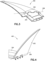
- the wing 102 also includes a folding wing portion 202 that is rotatably coupled to the fixed wing portion 204 by the folding wing hinge 210 so as to be selectively positioned between an unfolded position 300 (see Fig. 3 - (e.g., the flight position)) and a folded position 400 (see Fig.
- the folding wing portion 202 may have a swept or raked wing configuration 290 (as illustrated in Figs. 2A-2C ), a constant chord configuration 291, a tapered configuration 292, a reverse tapered configuration 293, an elliptical configuration 294, a semi-elliptical configuration 295 or any combination thereof.
- the folding wing hinge 210 is coupled to or at least partially formed by the fixed wing portion 204 so that the hinge axis 206 (and longitudinal axis 790 of hinge pin 600 described herein) extends in a direction that is parallel or substantially parallel with a centerline 105 of the fuselage 104 (see Fig. 2B ); while in other examples, the folding wing hinge 210 is coupled to or at least partially formed by the fixed wing portion 204 so that the hinge axis 206 (and longitudinal axis 790 of hinge pin 600 described herein) extends in a direction that is perpendicular or substantially perpendicular to the spar 250 of the fixed wing portion 204 (See Fig. 2C ). In still other examples, the hinge axis 206 may have any suitable spatial orientation relative to one or more of the fuselage 104 and fixed wing portion 204.
- the folding wing hinge 210 rotatably couples the fixed wing portion 204 to the folding wing portion 202 (the fixed wing portion 204 and the folding wing portion 202 being demarcated by the dashed line 500).
- the fixed wing portion 204 includes any suitable number of fixed hinge knuckles 510, 511, 512, 513.
- the folding wing portion 202 includes any suitable corresponding number of folding hinge knuckles 520, 521, 522, 523 that are interdigitated with the fixed hinge knuckles 510, 511, 512, 513.
- hinge pins 600, 601, 602 extend through respective ones of the fixed hinge knuckles 510, 511, 512, 513 and the folding hinge knuckles 520, 521, 522, 523 so as to rotatably couple the fixed wing portion 204 and the folding wing portion 202.
- hinge pin 602 extends through fixed hinge knuckle 510 and folding hinge knuckle 520
- hinge pin 601 extends through fixed hinge knuckle 511 and folding hinge knuckle 521
- hinge pin 600 extends through fixed hinge knuckles 512, 513 and folding hinge knuckles 522, 523.
- Fig. 6C is similar or substantially similar to Fig.
- hinge pin 602 extends through fixed hinge knuckle 513 and folding hinge knuckle 523
- hinge pin 601 extends through fixed hinge knuckle 512 and folding hinge knuckle 522
- hinge pin 600 extends through fixed hinge knuckles 510, 511 and folding hinge knuckles 520, 521.
- hinge pin 602 extends through fixed hinge knuckle 513 and folding hinge knuckle 523
- hinge pin 601 extends through fixed hinge knuckle 510 and folding hinge knuckle 520
- hinge pin 600 extends through fixed hinge knuckles 511, 512 and folding hinge knuckles 521, 522.
- the hinge pin 600 is fixedly coupled to the fixed wing portion 204, e.g., so that the hinge pin 600 does not rotate relative to the fixed wing portion 204.
- the hinge pin 600 is fixedly coupled to the folding wing portion 202, otherwise the operation and structure of the folding wing hinge 210 is similar or substantially similar between the examples illustrated in Figs. 6A-6C .
- the folding wing hinge includes the hinge pin 600, an input fitting 610, and a spline coupling member 620, where in Figs.
- the input fitting 610 and spline coupling member 620 non-rotatably couple the hinge pin 600 to, for example, the fixed hinge knuckle 512 of the fixed wing portion 204.
- the input fitting 610 and spline coupling member 620 non-rotatably couple the hinge pin 600 to, for example, the folding hinge knuckle 522 of the folding wing portion 202.
- the hinge pin 600 may be fixedly coupled to any suitable portion of one of the fixed wing portion 204 and the folding wing portion 202 where the rotary actuator 530 is disposed within (and coupled to) the other one of the fixed wing portion 204 and the folding wing portion 202.
- the hinge pin 600 includes a hinge pin spline 700 and a first longitudinal axis 790.
- the input fitting 610 is coupled to one of the fixed wing portion 204 and the folding wing portion 202. In the aspects illustrated in Figs. 6A , 6C , and 7A the input fitting 610 is coupled to the fixed wing portion 204; while in other aspects, such as illustrated in Fig. 6B , the input fitting 610 is coupled to the folding wing portion 202.
- the input fitting 610 includes an input fitting spline 705 and a second longitudinal axis 791.
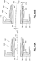
- the spline coupling member 620 has a spline coupling member 620 configured to couple with the hinge pin spline 700 and the input fitting spline 705 so that the first longitudinal axis 790 moves relative to the second longitudinal axis 791 by a first predetermined amount of movement 1000 (see Fig. 10B ), where the amount of movement is a linear distance 1010 and/or an angular rotation 1012 as shown in Fig. 10B .
- the spline coupling member 620 includes a first mating spline portion 711 that couples with the hinge pin spline 700 and a second mating spline portion 712 that couples with the input fitting spline 705.
- the spline coupling member 620 may couple with both the hinge pin spline 700 and the input fitting spline 705 with spline teeth that are common to both the hinge pin spline 700 and the input fitting spline 705.
- the hinge pin spline 700, the input fitting spline 705 and the spline(s) of the coupling member 620 may be involute splines, square splines (e.g., having parallel or substantially parallel sides) or any other suitable spline. Referring to Figs.
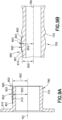
- the hinge pin spline 700 is an external spline 809 having teeth 800 with a crowned tooth surface 900.
- the crowned tooth surface 900 includes one or more of the sides 901, 902 of a respective tooth 800 and a top land or outer/top surface 903 of the respective tooth 800.
- the crowned tooth surface 900 is such that, a distance 950 between the sides 901, 902 at longitudinal ends 801, 802 of the respective tooth 800 is less than a distance 951 at a center portion 803 of the respective tooth 800.
- the difference in the distances 950, 951 is effected by a curvature of the respective sides (see Fig.
- the difference in the distances 950, 951 and the resulting changes in tooth thickness between the sides 901, 902 are apparent when the distances 950, 951 are measured from the first longitudinal axis 790 (or a constant/common distance from the first longitudinal axis) of the hinge pin 600, where the first longitudinal axis 790 forms a centerline of the hinge pin 600.
- the crowned tooth surface 900 is such that, a distance 952 between the outer surface 903 and the centerline of the part on which the tooth 800 is disposed (e.g., such as the first longitudinal axis 790 of the hinge pin 600) (see Fig. 9B ) at the longitudinal ends 801, 802 of the respective tooth 800 is less than a distance 953 between the outer surface 903 and the first longitudinal axis 790 at the center portion 803 of the respective tooth 800.
- the difference in the distances 952, 953 is effected by a curvature of the outer surface 903 (see Fig.
- outer surface 903 has a radius 960 of between about 22 inches (about 56 cm) and about 28 inches (about 71 cm). In other examples, the radius 960 may be more than about 28 inches (about 71 cm) or less than about 22 inches (about 56 cm).
- the first mating spline portion 711 of the spline coupling member 620 has an internal straight-sided spline 811 (e.g., having linear or un-crowned spline teeth 810 with tooth surfaces 810S - Fig. 8A ).
- the difference in the distances 950, 951 is effected by a curvature of the respective sides (see Fig. 8B ), where respective sides have a radius 860 of between about 38 inches (about 97 cm) and about 48 inches (about 122 cm). In other examples, the radius 860 may be more than about 48 inches (about 122 cm) or less than about 38 inches (about 97 cm).
- the difference in the distances 950, 951 and the resulting changes in tooth thickness between the sides 901, 902 are apparent when the distances 950, 951 are measured from the second longitudinal axis 791 (or a constant/common distance from the second longitudinal axis) of the input fitting 610, where the second longitudinal axis 791 forms a centerline of the input fitting 610.
- the crowned tooth surface 780 is such that, the distance 952 between the outer surface 903 and the second longitudinal axis 791 at the longitudinal ends 801, 802 of the respective tooth 770 is less than a distance 953 between the outer surface 903 and the second longitudinal axis 791 at the center portion 803 of the respective tooth 770.
- the difference in the distances 952, 953 is effected by a curvature of the outer surface 903 (see Fig. 9A ), where outer surface 903 has a radius 960 of between about 22 inches (about 56 cm) and about 28 inches (about 71 cm).
- the radius 960 may be more than about 28 inches (about 71 cm) or less than about 22 inches (about 56 cm).
- the second mating spline portion 712 of the spline coupling member 620 has an internal straight-sided spline 811 (see Figs. 8A and 8B - e.g., having linear or un-crowned spline teeth 810). It is noted that where the spline coupling member 620 includes a crowned spline, the crowned spline of the spline coupling member 620 is similar or substantially similar to that described above with respect to the input fitting 610 and the hinge pin 600.
- the crowned spline has constant profile teeth, where each tooth follows a curved path 910 having the radius 960.
- the crowned sides 901, 902 have an effective radius 860 when that radius 860 is measured from the reference datum described above.
- the hinge pin spline 700 is an external spline having teeth 800 with a crowned tooth surface 900 as described above.
- the input fitting spline 705A is an internal straight-sided spline 709A having straight un-crowned teeth 810A (similar or substantially similar to teeth 810 described herein with tooth surfaces 810S).
- the first mating spline portion 711 of the spline coupling member 620 is as described above however, the second mating spline portion 712A has teeth 775, each having a crowned tooth surface 785 that is similar or substantially similar to crowned tooth surfaces 780, 900.
- the respective crowned tooth surfaces 780, 900 of each of the hinge pin spline 700 and the input fitting spline 705 form respective universal joints 1020, 1021 (e.g., splined universal joints) with the spline coupling member 620.
- the crowned tooth surface 785 also forms a universal joint 1022 with the spline coupling member 620 similar or substantially similar to universal joints 1020, 1021.
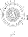
- the universal joint 1020, 1021, 1022 (e.g., splined universal joint) as used herein is a joint that provides two degree of freedom pivoting motion in directions 798, 799 (see Fig. 7B ) between two shafts (e.g., such as between the hinge pin 600 and the spline coupling member 620 and between the spline coupling member 620 and the input fitting 610) while also providing a splined coupling between the shafts.
- the crowned tooth surfaces 780, 785, 900 provide increasing clearance between each of the hinge pin spline 700 and the input fitting spline 705 with a respective one of the first mating spline portion 711 and the second mating spline portion 712 of the spline coupling member 620, where the clearance increases from the center portion 803 of the teeth 770, 775, 800 towards the longitudinal ends 801, 802 of the teeth 770, 800.
- This clearance provides for relative pivoting movement between the hinge pin spline 700 and the first mating spline portion 711 about a contact area 840 ( Fig.
- teeth 770, 775 formed between the crowned sides 901, 902 of the teeth 770, 775, 800 and mating spline tooth surfaces 850, 851.
- At least one hinge pin bushing 760, 761 (see in Fig. 7A with respect to hinge pin 600, noting similar hinge pin bushings may be provided for hinge pins 601, 602) is coupled to at least one of the fixed wing portion 204 and the folding wing portion 202.
- hinge pin bushing 760 is coupled to the fixed wing portion 204 and hinge pin bushing 761 is coupled to the folding wing portion 202.
- the hinge pin 600 extends through the at least one hinge pin bushing 760, 761 so that the hinge pin 600 is supported by the at least one hinge pin bushing 760, 761 about a third longitudinal axis 792 of the at least one hinge pin bushing 760, 761.
- the first longitudinal axis 790 moves relative to the third longitudinal axis 792 by a second predetermined amount of movement 740 (shown as a linear distance in Fig. 7A but may be a linear rotation in addition to or in lieu of the linear distance).
- the second predetermined amount of movement 740 is less than the first predetermined amount of movement 1000 so that flight loads 720 between the fixed wing portion 204 and the folding wing portion 202 are isolated or substantially isolated to a load path 721 that passes through the at least one hinge pin bushing 760.
- the coupling between the spline coupling member 620 and both of the hinge pin 600 and input fitting 610 is configured to decouple the flight loads 720 between the fixed wing portion 204 and the folding wing portion 202 (e.g., prevents or substantially prevents flight loads from passing through the hinge pin spline 700, the input fitting spline 705 and the spline coupling member 620).
- the splined coupling (e.g., crowned spline coupling) between the hinge pin 600 and the spline coupling member 620 provides for axial misalignment between the hinge pin 600 and the spline coupling member 620 such that the first longitudinal axis 790 and a coupling member longitudinal axis 793 can pivot relative to one another in directions 798, 799 ( Fig. 7B ).
- the splined coupling (e.g., crowned spline coupling) between the input fitting 610 and the spline coupling member 620 provides for axial misalignment between the input fitting 610 and the spline coupling member 620 such that the second longitudinal axis 791 and the coupling member longitudinal axis 793 can pivot relative to one another in directions 798, 799 ( Fig. 7B ).
- two sets of crowned spline couplings e.g., the first set between the input fitting 610 and the spline coupling member 620 and the second set between the spline coupling member 620 and the hinge pin 600
- the crowned spline couplings provide for a greater amount of movement (e.g. translation in directions 798, 799) between the hinge pin 600 and the input fitting 610 than allowed between the at least one hinge pin bushing 760, 761 and the hinge pin 600 such that contact is made between the hinge pin 600 and the at least one hinge pin bushing 760, 761 before the crowned spline couplings reach their limits of motion thereby decoupling (e.g., isolating) the torsional loads 750 transmitted through the crowned spline couplings for folding/unfolding the folding wing portion 202 from the flight loads 720.
- decoupling e.g., isolating
- the crowned splined couplings as described herein may also ease manufacturing tolerances because the relative movement between the hinge pin 600 and the input fitting 610 provides for relaxed position accuracy when locating the input fitting relative to the hinge axis 206 (which may be defined by, e.g., the third longitudinal axis 792 of the hinge pin bushings at least one hinge pin bushing 760, 761).
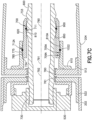
- the hinge pin 600 includes a first protrusion 733 ( Figs. 7A and 7C ) configured to prevent longitudinal movement of the spline coupling member 620 relative to the hinge pin 600 in a first longitudinal direction 789.
- the input fitting 610 includes a second protrusion 734 ( Figs. 7A and 7C ) configured to prevent longitudinal movement of the spline coupling member 620 relative to the hinge pin 600 in a second longitudinal direction 788, the second longitudinal direction 788 being opposite the first longitudinal direction 789.
- rotary actuator 530 is coupled to the hinge pin 600 to effect folding and unfolding of the folding wing portion 202 relative to the fixed wing portion 204.
- the coupling between the rotary actuator and the hinge pin 600 may be any suitable coupling such as a spline coupling 730.
- the rotary actuator 530 is coupled to another of the fixed wing portion 204 and the folding wing portion 202 (e.g., where the input fitting 610 is coupled to the fixed wing portion 204 the rotary actuator 530 is coupled to the folding wing portion 202 and where input fitting 610 is coupled to the folding wing portion 202 the rotary actuator 530 is coupled to the fixed wing portion 204) so as to provide relative rotation between the hinge pin 600 and the rotary actuator 530.
- the folding wing hinge 210 may be provided with additional features that may provide for movement of one or more of the hinge pin 600 and the input fitting 610 relative to the at least one hinge pin bushing 760, 761 for decoupling the flight loads 720 ( Fig. 7A ) and the torsional loads 750 ( Fig. 7B ) such that the flight loads are directed through the load path 721 ( Fig. 7A ) rather than through the splined coupling between the hinge pin 600 and the input fitting 610.
- the input fitting 610 is coupled to the one of the fixed wing portion 204 and the folding wing portion 202 with a coupling 1100 that effects relative movement (e.g., in directions 798, 799 - Fig. 7B ) between the input fitting 610 and the one of the fixed wing portion 204 and the folding wing portion 202 so that the flight loads 720 ( Fig. 7A ) between the fixed wing portion 204 and the folding wing portion 202 are isolated or substantially isolated to the load path 721 ( Fig.
- the input fitting 610 and/or one of the fixed wing portion 204 and the folding wing portion 202 may have a fastener aperture 1150 that is larger than a diameter of a fastener 1155 coupling the input fitting 610 to the one of the fixed wing portion 204 and the folding wing portion 202.
- the fastener aperture 1150 may be sized relative to the fastener 1155 and/or the fastener 1155 may be tightened to a predetermined torque specification that provides for relative movement between the input fitting 610 and the one of the fixed wing portion 204 and the folding wing portion 202 where the relative movement is greater than the second predetermined amount of movement 740 between the hinge pin 600 and the at least one hinge pin bushing 760, 761 so that the first longitudinal axis 790 of the hinge pin 600 moves relative to the third longitudinal axis 792 of the at least one hinge pin bushing 760, 761 to isolate or substantially isolate the flight loads 720 between the fixed wing portion 204 and the folding wing portion 202 to the load path 721 that passes through the at least one hinge pin bushing 760, 761.
- the input fitting 610 includes a flanged end 611 and a free end 612, where the flanged end 611 and the free end 612 are separated by a longitudinal length 613 that effects deflection of the free end 612 under flight loads 720 relative to the flanged end 611 so that the first longitudinal axis 790 of the hinge pin 600 moves relative to the third longitudinal axis 792 of the at least one hinge pin bushing 760, 761 to isolate or substantially isolate the flight loads 720 between the fixed wing portion 204 and the folding wing portion 202 to the load path 721 that passes through the at least one hinge pin bushing 760, 761.
- a tooth-to-tooth interface 1170 of one or more of the hinge pin spline 700 and the input fitting spline 705, 705A with the spline coupling member 620 effects a third predetermined amount of movement 1120 ( Fig. 11 ) between teeth of the spline coupling member 620 and teeth of one or more of the hinge pin spline 700 and the input fitting spline 705, 705A.
- the second predetermined amount of movement 740 is less than the third predetermined amount of movement 1120 so that the flight loads 720 ( Fig.
- clearance 1121 (corresponding to the third predetermined amount of movement 1120) may be provided between the teeth 1131 (which may be straight teeth or crowned teeth as described above) of the input fitting spline 1130 (which may be an internal or external spline, where an internal spline is illustrated in Fig. 11 for exemplary purposes only) and the teeth 1141 (which may be straight teeth or crowned teeth as described above) of the hinge pin spline 1140 (which may be an internal or external spline, where an external spline is illustrated in Fig.
- the clearance 1121 may be greater than the second predetermined amount of movement 740 between the hinge pin 600 and the at least one hinge pin bushing 760, 761 so that the first longitudinal axis 790 of the hinge pin 600 moves relative to the third longitudinal axis 792 of the at least one hinge pin bushing 760, 761 to isolate or substantially isolate the flight loads 720 between the fixed wing portion 204 and the folding wing portion 202 to the load path 721 that passes through the at least one hinge pin bushing 760, 761.
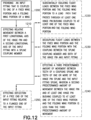
- the method includes providing an input fitting 610 that is coupled to one of a fixed wing portion 204 and a folding wing portion 202 of a wing 120 ( Fig. 12 , Block 1200), wherein the input fitting 610 includes an input fitting spline 705, 705A coupled with a hinge pin spline 700 of a hinge pin 600.
- Relative movement is effected between a first longitudinal axis 790 of the hinge pin 600 and a second longitudinal axis 791 of the input fitting 610 with a spline coupling member 620 having a spline coupling member 620 configured to couple with the hinge pin spline 700 and the input fitting spline 705, 705A so that the first longitudinal axis 790 moves relative to the second longitudinal axis 791 by a first predetermined amount of movement 1000 ( Fig. 10B ).
- the flight loads 720 between the fixed wing portion 204 and the folding wing portion 202 are isolated or substantially isolated to the load path 721 that passes through at least one hinge pin bushing 760, 761 coupled to at least one of the fixed wing portion 204 and the folding wing portion 202 ( Fig. 12 , Block 1220).
- the at least one hinge pin bushing 760, 761 has a third longitudinal axis 792 and the first longitudinal axis 790 of the hinge pin 600 moves relative to the third longitudinal axis 792 by the second predetermined amount of movement 740.
- relative movement between the input fitting 610 and the one of the fixed wing portion 204 and the folding wing portion 202 is effected so that flight loads 720 between the fixed wing portion 204 and the folding wing portion 202 are isolated or substantially isolated to the load path 721 that passes through at least one hinge pin bushing 760, 761 coupled to at least one of the fixed wing portion 204 and the folding wing portion 202, where the hinge pin 600 extends through the at least one hinge pin bushing 760, 761.
- the flight loads 720 are decoupled between the fixed wing portion 204 and the folding wing portion 202 with the coupling between the spline coupling member 620 and both of the hinge pin 600 and input fitting 610 ( Fig.
- deflection of the free end 612 of the input fitting 610 is effected relative to the flanged end 611 of the input fitting 610 ( Fig. 12 , Block 1250) with the longitudinal length 613 of the input fitting 610 so that the first longitudinal axis 790 of the hinge pin 600 moves relative to the third longitudinal axis 792 of the at least one hinge pin bushing 760, 761 to isolate or substantially isolate flight loads 720 between the fixed wing portion 204 and the folding wing portion 202 to the load path 721
- the method may also include preventing longitudinal movement of the spline coupling member 620 relative to the hinge pin 600 in the first longitudinal direction 789 with the first protrusion 733 of the hinge pin 600. Longitudinal movement of the spline coupling member 620 relative to the hinge pin 600 may also be prevented in the second longitudinal direction 788, the second longitudinal direction 788 being opposite the first longitudinal direction 789, with the second protrusion 734 of the input fitting 610.
- the method may also include effecting the third predetermined amount of movement 1120 ( Fig. 11 ), with a tooth-to-tooth interface 1170 of one or more of the hinge pin spline 700 and the input fitting spline 705, 705A with the spline coupling member 620, between teeth of the spline coupling member 620 and teeth of the one or more of the hinge pin spline 700 and the input fitting spline 705, 705A, wherein the second predetermined amount of movement 740 between the hinge pin 600 and at least one hinge pin bushing 760, 761 coupled to at least one of the fixed wing portion 204 and the folding wing portion 202 is less than the third predetermined amount of movement 1120 so that flight loads 720 between the fixed wing portion 204 and the folding wing portion 202 are isolated or substantially isolated to the load path 721.
- Coupled means associated directly as well as indirectly.
- a member A may be directly associated with a member B, or may be indirectly associated therewith, e.g., via another member C.
- couplings other than those depicted in the drawings may also exist.
- Dashed lines, if any, connecting blocks designating the various elements and/or components represent couplings similar in function and purpose to those represented by solid lines; however, couplings represented by the dashed lines may either be selectively provided or may relate to alternative examples of the present disclosure.
- elements and/or components, if any, represented with dashed lines indicate alternative examples of the present disclosure.
- the blocks may represent operations and/or portions thereof and lines connecting the various blocks do not imply any particular order or dependency of the operations or portions thereof. Blocks represented by dashed lines, if any, indicate alternative operations and/or portions thereof. Dashed lines, if any, connecting the various blocks represent alternative dependencies of the operations or portions thereof. It will be understood that not all dependencies among the various disclosed operations are necessarily represented.
- Fig. 12 and the accompanying disclosure describing the operations of the method(s) set forth herein should not be interpreted as necessarily determining a sequence in which the operations are to be performed. Rather, although one illustrative order is indicated, it is to be understood that the sequence of the operations may be modified when appropriate. Accordingly, certain operations may be performed in a different order or simultaneously or substantially simultaneously. Additionally, those skilled in the art will appreciate that not all operations described need be performed.
- first, second, etc. are used herein merely as labels, and are not intended to impose ordinal, positional, or hierarchical requirements on the items to which these terms refer. Moreover, reference to, e.g., a “second” item does not require or preclude the existence of, e.g., a "first” or lower-numbered item, and/or, e.g., a "third" or higher-numbered item.
- a system, apparatus, structure, article, element, component, or hardware “configured to” perform a specified function is indeed capable of performing the specified function without any alteration, rather than merely having potential to perform the specified function after further modification.
- the system, apparatus, structure, article, element, component, or hardware “configured to” perform a specified function is specifically selected, created, implemented, utilized, programmed, and/or designed for the purpose of performing the specified function.
- "configured to” denotes existing characteristics of a system, apparatus, structure, article, element, component, or hardware which enable the system, apparatus, structure, article, element, component, or hardware to perform the specified function without further modification.
- a system, apparatus, structure, article, element, component, or hardware described as being “configured to” perform a particular function may additionally or alternatively be described as being “adapted to” and/or as being “operative to” perform that function.
Landscapes
- Engineering & Computer Science (AREA)
- Aviation & Aerospace Engineering (AREA)
- Mechanical Engineering (AREA)
- Manufacturing & Machinery (AREA)
- Transportation (AREA)
- Automation & Control Theory (AREA)
- Tires In General (AREA)
- Pivots And Pivotal Connections (AREA)
Claims (15)
- Klappflügelscharnier (210) für einen Flügel (102) mit einem feststehenden Flügelabschnitt (204) und einem klappbaren Flügelabschnitt (202), wobei das Klappflügelscharnier (210) umfasst:einen Scharnierbolzen (600) mit einer Scharnierbolzenverzahnung (700) und einer ersten Längsachse (790);ein Eingangsanschlussstück (610), das mit einem von dem feststehenden Flügelabschnitt (204) und dem klappbaren Flügelabschnitt (202) gekoppelt ist, wobei das Eingangsanschlussstück (610) eine Eingangsanschlussverzahnung (705, 705A) und eine zweite Längsachse (791) umfasst; undein Verzahnungskupplungselement (620), das konfiguriert ist, um mit der Scharnierbolzenverzahnung (700) und der Eingangsanschlussverzahnung (705, 705A) gekoppelt zu werden, so dass die erste Längsachse (790) relativ zu der zweiten Längsachse (791) um einen ersten vorgegebenen Bewegungsbetrag (1000) beweglich ist;wobei die Scharnierbolzenverzahnung (700) eine Außenverzahnung (809) mit Zähnen (800) mit einer balligen Zahnoberfläche (900) ist und das Verzahnungskupplungselement (620) einen ersten Gegenverzahnungsabschnitt (711) mit einer geradseitigen Innenverzahnung (811) umfasst, die zum Kuppeln mit der Scharnierbolzenverzahnung (700) konfiguriert ist; undwobei:a) die Eingangsanschlussverzahnung (705) eine Außenverzahnung (709) mit Zähnen (770) mit einer balligen Zahnoberfläche (780) ist und das Verzahnungskupplungselement (620) einen zweiten Gegenverzahnungsabschnitt (712) mit einer geradseitigen Innenverzahnung (811) umfasst, die zum Koppeln mit der Eingangsanschlussverzahnung (705) konfiguriert ist, wobei die jeweiligen balligen Zahnoberflächen der Scharnierbolzenverzahnung (700) und der Eingangsanschlussverzahnung (705) jeweilige Kardangelenke (1020, 1021) mit dem Verzahnungskupplungselement (620) bilden; oderb) die Eingangsanschlussverzahnung (705A) eine geradseitige Innenverzahnung (709A) ist und das Verzahnungskupplungselement (620) einen zweiten Gegenverzahnungsabschnitt (712A) mit Zähnen (775) mit einer balligen Zahnoberfläche (785) umfasst, die zum Koppeln mit der Eingangsanschlussverzahnung (705) konfiguriert ist, wobei ballige Zahnoberflächen (900) der Scharnierbolzenverzahnung (700) und Zahnoberflächen (810S) der Eingangsanschlussverzahnung (705A) jeweilige Kardangelenke (1020, 1022) mit dem Verzahnungskupplungselement (620) bilden.
- Klappflügelscharnier (210) nach Anspruch 1, bei dem:der feststehende Flügelabschnitt (204) einen oder mehrere feststehende Scharnierbuchsen (510, 511, 512, 513) umfasst;der Klappflügelabschnitt (202) ein oder mehrere klappbare Scharnierbuchsen (520, 521 , 522, 523) umfasst, die mit den feststehenden Scharnierbuchsen (510, 511, 512, 513) ineinandergreifen; undder Scharnierbolzen (600) sich durch jeweils eine der feststehenden Scharnierbuchsen (510, 511, 512, 513) und der klappbaren Scharnierbuchsen (520, 521, 522, 523) erstreckt, um den feststehenden Flügelabschnitt (204) und den klappbaren Flügelabschnitt (202) drehbar zu koppeln.
- Klappflügelscharnier (210) nach Anspruch 1 oder 2, ferner umfassend:
einen Drehaktuator (530), der mit dem jeweils anderen von feststehendem Flügelabschnitt (204) und klappbarem Flügelabschnitt (202) gekoppelt ist, wobei der Drehaktuator (530) mit dem Scharnierbolzen (600) gekoppelt ist, um das Ein- und Ausklappen des klappbaren Flügelabschnitts (202) relativ zum feststehenden Flügelabschnitt (204) zu bewirken. - Klappflügelscharnier (210) nach einem der Ansprüche 1-3, bei dem die jeweiligen balligen Zahnflächen der Scharnierbolzenverzahnung (700) und der Eingangsanschlussverzahnung (705, 705A) einen Radius zwischen 56 cm (22 Zoll) und 71 cm (28 Zoll) oder zwischen etwa 56 cm (etwa 22 Zoll) und etwa 71 cm (etwa 28 Zoll) aufweisen.
- Klappflügelscharnier (210) nach einem der Ansprüche 1-3, bei dem die ballige Zahnoberfläche (785) der Zähne des zweiten Gegenverzahnungsabschnitts (712, 712A) in Option b) von Anspruch 1 einen Radius von zwischen 56 cm (22 Zoll) und 71 cm (28 Zoll); oder zwischen etwa 56 cm (etwa 22 Zoll) und etwa 71 cm (etwa 28 Zoll) aufweisen.
- Klappflügelscharnier (210) nach einem der Ansprüche 1-3, bei dem die ballige Zahnoberfläche (900) der Zähne (800) der Scharnierbolzenverzahnung (700) einen Radius zwischen 56 cm (22 Zoll) und 71 cm (28 Zoll); oder zwischen etwa 56 cm (etwa 22 Zoll) und etwa 71 cm (etwa 28 Zoll) aufweist.
- Klappflügelscharnier (210) nach einem der vorhergehenden Ansprüche, bei dem eine oder mehrere von der der Scharnierbolzenverzahnung (700), der Eingangsanschlussverzahnung (705, 705A), dem ersten Gegenverzahnungsabschnitt (711) und dem zweiten Gegenverzahnungsabschnitt (712, 712A) eine Vierkantverzahnung ist.
- Klappflügelscharnier (210) nach einem der vorhergehenden Ansprüche, bei dem eine oder mehrere von der Scharnierbolzenverzahnung (700), der Eingangsverbindungsverzahnung (705, 705A), dem ersten Gegenverzahnungsabschnitt (711) und dem zweiten Gegenverzahnungsabschnitt (712, 712A) eine Evolventenverzahnung ist.
- Klappflügelscharnier (210) nach einem der vorhergehenden Ansprüche, bei dem der Scharnierbolzen (600) einen ersten Vorsprung (733) umfasst, der konfiguriert ist, um eine Längsbewegung des Verzahnungskupplungselements (620) relativ zum Scharnierbolzen (600) in einer ersten Längsrichtung (789) zu verhindern.
- Klappflügelscharnier nach Anspruch 9, bei dem das Eingangsanschlussstück (610) einen zweiten Vorsprung (734) umfasst, der konfiguriert ist, um eine Längsbewegung des Verzahnungskupplungselements (620) relativ zum Scharnierbolzen (600) in einer zweiten Längsrichtung (788) zu verhindern, wobei die zweite Längsrichtung (788) der ersten Längsrichtung (789) entgegengesetzt ist.
- Flügel (102) mit:einem feststehenden Flügelabschnitt (204) und einem klappbaren Flügelabschnitt (202); unddem Klappflügelscharnier (210) nach einem der vorhergehenden Ansprüche.
- Flugzeug (100) mit:einem Flügel (102) mit einem feststehenden Flügelabschnitt (204) und einem klappbaren Flügelabschnitt (202); unddem Klappflügelscharnier (210) nach einem der Ansprüche 1-10.
- Verfahren zum weitgehenden Isolieren von Fluglasten (720) in einem Klappflügelscharnier (210), wobei das Verfahren umfasst:Bereitstellen eines Eingangsanschlussstücks (610), das mit einem von einem festen Flügelabschnitt (204) und einem klappbaren Flügelabschnitt (202) eines Flügels (102) verbunden ist, wobei das Eingangsanschlussstück (610) eine Eingangsanschlussverzahnung (705, 705A) umfasst, die mit einer Scharnierbolzenverzahnung (700) eines Scharnierbolzens (600) verbunden ist;Bewirken einer Relativbewegung zwischen einer ersten Längsachse (790) des Scharnierbolzens (600) und einer zweiten Längsachse (791) des Eingangsanschlussstücks (610) mit einem Verzahnungskupplungselement (620), das konfiguriert ist, um mit der Scharnierbolzenverzahnung (700) und der Eingangsanschlussverzahnung (705, 705A) gekoppelt zu werden, so dass sich die erste Längsachse (790) relativ zu der zweiten Längsachse (791) um einen ersten vorgegebenen Bewegungsbetrag (1000) bewegt;Bewirken einer Relativbewegung zwischen der ersten Längsachse (790) des Scharnierbolzens (600) und der zweiten Längsachse (791) des Eingangsanschlusses (610), wobei die Scharnierbolzenverzahnung (700) eine Außenverzahnung (809) mit Zähnen (800) mit einer balligen Zahnoberfläche (900) ist und das Verzahnungskupplungselement (620) einen ersten Gegenverzahnungsabschnitt (711) mit einer geradseitigen Innenverzahnung (811) umfasst; undeines von:a) Bewirken einer Relativbewegung zwischen der ersten Längsachse (790) des Scharnierbolzens (600) und der zweiten Längsachse (791) des Eingangsanschlussstücks (610), wobei die Eingangsanschlussverzahnung (705, 705A) eine Außenverzahnung (709) mit Zähnen (770) mit einer balligen Zahnoberfläche (780) ist, und wobei das Verzahnungskupplungselement (620) einen zweiten Gegenverzahnungsabschnitt (712) mit einer geradseitigen Innenverzahnung (811) umfasst, die zum Koppeln mit der Eingangsanschlussverzahnung (705) konfiguriert ist; undb) Bewirken einer Relativbewegung zwischen der ersten Längsachse (790) des Scharnierbolzens (600) und der zweiten Längsachse (791) des Eingangsanschlussstücks (610), wobei die Eingangsanschlussverzahnung (705, 705A) eine geradseitige Innenverzahnung (709A) ist und das Verzahnungskupplungselement (620) einen zweiten Gegenverzahnungsabschnitt (712A) mit Zähnen (775) mit einer balligen Zahnoberfläche (785) aufweist, die zum Koppeln mit der Eingangsanschlussverzahnung (705) konfiguriert ist.
- Verfahren nach Anspruch 13, ferner umfassend das Verhindern einer Längsbewegung des Verzahnungskupplungselements (620) relativ zum Scharnierbolzen (600) in einer ersten Längsrichtung (789) mit einem ersten Vorsprung (733) des Scharnierbolzens (600).
- Verfahren nach Anspruch 14, ferner umfassend das Verhindern einer Längsbewegung des Verzahnungskupplungselements (620) relativ zum Scharnierbolzen (600) in einer zweiten Längsrichtung (788), wobei die zweite Längsrichtung (788) der ersten Längsrichtung (789) entgegengesetzt ist, mit einem zweiten Vorsprung (734) des Eingangsanschlussstücks (610).
Applications Claiming Priority (2)
| Application Number | Priority Date | Filing Date | Title |
|---|---|---|---|
| US16/056,126 US11066148B2 (en) | 2018-08-06 | 2018-08-06 | Folding wing hinge, aircraft and method therefor |
| EP19189747.9A EP3608220B1 (de) | 2018-08-06 | 2019-08-02 | Klappflügelscharnier, flugzeug und verfahren dafür |
Related Parent Applications (2)
| Application Number | Title | Priority Date | Filing Date |
|---|---|---|---|
| EP19189747.9A Division EP3608220B1 (de) | 2018-08-06 | 2019-08-02 | Klappflügelscharnier, flugzeug und verfahren dafür |
| EP19189747.9A Division-Into EP3608220B1 (de) | 2018-08-06 | 2019-08-02 | Klappflügelscharnier, flugzeug und verfahren dafür |
Publications (2)
| Publication Number | Publication Date |
|---|---|
| EP4043338A1 EP4043338A1 (de) | 2022-08-17 |
| EP4043338B1 true EP4043338B1 (de) | 2025-03-26 |
Family
ID=67539337
Family Applications (2)
| Application Number | Title | Priority Date | Filing Date |
|---|---|---|---|
| EP19189747.9A Active EP3608220B1 (de) | 2018-08-06 | 2019-08-02 | Klappflügelscharnier, flugzeug und verfahren dafür |
| EP22166033.5A Active EP4043338B1 (de) | 2018-08-06 | 2019-08-02 | Klappflügelscharnier, flugzeug und verfahren dafür |
Family Applications Before (1)
| Application Number | Title | Priority Date | Filing Date |
|---|---|---|---|
| EP19189747.9A Active EP3608220B1 (de) | 2018-08-06 | 2019-08-02 | Klappflügelscharnier, flugzeug und verfahren dafür |
Country Status (3)
| Country | Link |
|---|---|
| US (1) | US11066148B2 (de) |
| EP (2) | EP3608220B1 (de) |
| CN (1) | CN110816810B (de) |
Families Citing this family (15)
| Publication number | Priority date | Publication date | Assignee | Title |
|---|---|---|---|---|
| US11440638B2 (en) * | 2018-05-03 | 2022-09-13 | Airbus Operations Gmbh | Wing for an aircraft |
| CN110525635A (zh) * | 2018-05-25 | 2019-12-03 | 空中客车德国运营有限责任公司 | 用于飞行器的机翼和飞行器 |
| US11370526B2 (en) * | 2018-05-31 | 2022-06-28 | Airbus Operations Gmbh | Latching device for a wing arrangement for an aircraft |
| US11319054B2 (en) * | 2018-05-31 | 2022-05-03 | Airbus Operations Gmbh | Wing arrangement for an aircraft |
| US11214353B2 (en) * | 2018-06-01 | 2022-01-04 | Airbus Operations Gmbh | Wing arrangement for an aircraft and aircraft |
| EP3587252A1 (de) * | 2018-06-28 | 2020-01-01 | Airbus Operations GmbH | Arretiersystem zum arretieren einer ersten flugzeugkomponente in bezug auf eine zweite flugzeugkomponente |
| US11945578B2 (en) | 2021-10-18 | 2024-04-02 | The Boeing Company | Apparatus and methods for limiting trailing edge deflection in aircraft folding wing tips |
| EP4177160A1 (de) | 2021-11-04 | 2023-05-10 | Goodrich Actuation Systems Limited | Befestigung für einen drehantrieb am flügel |
| CN114348238B (zh) * | 2021-12-23 | 2024-01-16 | 中国商用飞机有限责任公司北京民用飞机技术研究中心 | 一种拉杆式飞机折叠翼梢及其操作方法 |
| GB2616252A (en) * | 2022-01-31 | 2023-09-06 | Airbus Operations Ltd | Aircraft with movable wing tip device |
| GB2615311A (en) * | 2022-01-31 | 2023-08-09 | Airbus Operations Ltd | Aircraft wing with movable wing tip device |
| US11932378B2 (en) * | 2022-02-09 | 2024-03-19 | The Boeing Company | Actuated assemblies, kits, aircraft, and methods of utilizing the same |
| GB2628523B (en) * | 2022-11-16 | 2025-07-09 | Airbus Operations Ltd | Aircraft wing |
| CN117208196A (zh) * | 2023-10-07 | 2023-12-12 | 南京航空航天大学 | 一种自适应桨叶及飞机 |
| TR2024008342A1 (tr) * | 2024-06-28 | 2026-01-21 | Tusas Tuerk Havacilik Ve Uzay Sanayii Anonim Sirketi | Bir hareket mekanizması. |
Family Cites Families (51)
| Publication number | Priority date | Publication date | Assignee | Title |
|---|---|---|---|---|
| US2881994A (en) * | 1953-11-09 | 1959-04-14 | Northrop Aircraft Inc | Convex panel wing construction |
| US3030052A (en) | 1959-01-22 | 1962-04-17 | Curtiss Wright Corp | Mechanical remote control system |
| US3081053A (en) * | 1960-04-14 | 1963-03-12 | Martin E Jarrell | Locking and unlocking mechanism |
| US4778129A (en) | 1987-03-12 | 1988-10-18 | The Boeing Company | Control surface drive for folding wing aircraft |
| US4856379A (en) | 1987-09-22 | 1989-08-15 | Allied-Signal Inc. | Non-jamming rotary mechanical actuator |
| US4979700A (en) * | 1988-10-28 | 1990-12-25 | Curtiss Wright Flight Systems, Inc. | Rotary actuator for leading edge flap of aircraft |
| US5310138A (en) * | 1991-12-30 | 1994-05-10 | Alliedsignal Inc. | Wing fold actuator system for aircraft |
| US5201479A (en) * | 1992-01-30 | 1993-04-13 | The Boeing Company | Self-monitoring latch pin lock for folding wing aircraft |
| US5350135A (en) | 1992-01-30 | 1994-09-27 | The Boeing Company | Latch pin inhibitor for folding wing-tip aircraft |
| US5452643A (en) | 1992-01-30 | 1995-09-26 | The Boeing Company | Hydraulic power drive unit |
| US5381986A (en) * | 1992-01-30 | 1995-01-17 | The Boeing Company | Folding wing-tip system |
| US5558299A (en) * | 1994-04-19 | 1996-09-24 | Mcdonnell Douglas Corporation | Wing fold push-pin locking assembly |
| GB2299562A (en) | 1995-04-01 | 1996-10-09 | Nigel Howard Mckrill | Actuator for helicopter rotor blade aileron |
| US6082665A (en) * | 1998-07-27 | 2000-07-04 | Spitzer; Jeffrey J. | Roadable aircraft |
| US6270039B1 (en) * | 1999-10-12 | 2001-08-07 | Patria Finavicomp Oy | Hinge for movable control surfaces in an aircraft and a connecting piece to be used with such a hinge |
| US6834835B1 (en) * | 2004-03-12 | 2004-12-28 | Qortek, Inc. | Telescopic wing system |
| US7322545B2 (en) | 2005-12-29 | 2008-01-29 | The Boeing Company | Structural mechanism for unlocking and engaging a controllable surface on a hinged platform (wing) |
| FR2911320B1 (fr) * | 2007-01-16 | 2009-04-10 | Sagem Defense Securite | Voilure d'aeronef en plusieurs elements demontables |
| US7975965B2 (en) * | 2008-05-13 | 2011-07-12 | The Boeing Company | Wing tip joint in airfoils |
| US8157206B2 (en) * | 2008-06-11 | 2012-04-17 | Icon Aircraft, Inc. | Two-motion wing-fold mechanism with independent load path |
| US8393791B2 (en) * | 2009-08-17 | 2013-03-12 | The Boeing Company | Bearing side face electrical isolation |
| GB0919019D0 (en) | 2009-10-30 | 2009-12-16 | Airbus Operations Ltd | Aerofoil |
| US10538307B2 (en) | 2011-10-01 | 2020-01-21 | The Boeing Company | Hinged raked wing tip |
| US9908612B2 (en) | 2011-10-01 | 2018-03-06 | The Boeing Company | Fold wing tip having stub spar |
| US9499252B2 (en) * | 2011-10-01 | 2016-11-22 | The Boeing Company | Wing fold controller |
| US9296469B2 (en) | 2011-10-01 | 2016-03-29 | The Boeing Company | Horizontal folding wingtip |
| US9211946B2 (en) | 2011-10-01 | 2015-12-15 | The Boeing Company | Wing fold system with latch pins through multiple mating lugs |
| US9290260B2 (en) | 2011-10-01 | 2016-03-22 | The Boeing Company | Wing fold controller |
| US8946607B2 (en) | 2011-12-13 | 2015-02-03 | The Boeing Company | Mechanisms for deploying and actuating airfoil-shaped bodies on unmanned aerial vehicles |
| GB201209666D0 (en) * | 2012-05-31 | 2012-07-18 | Airbus Operations Ltd | A hinge assembly for rotatably mounting a control surface on an aircraft |
| US8733692B2 (en) * | 2012-06-11 | 2014-05-27 | The Boeing Company | Latching apparatus and methods |
| US9469392B2 (en) | 2012-10-30 | 2016-10-18 | The Boeing Company | Wing fold system rotating latch |
| US9914523B2 (en) | 2012-10-30 | 2018-03-13 | The Boeing Company | Wing hinge assembly including hinged torque boxes |
| US9415857B2 (en) | 2012-10-30 | 2016-08-16 | The Boeing Company | Wing fold system |
| US9481446B2 (en) * | 2012-10-30 | 2016-11-01 | The Boeing Company | System for latching and locking a foldable airfoil |
| US9296472B2 (en) | 2013-10-17 | 2016-03-29 | The Boeing Company | Wingtip control system |
| US9580166B2 (en) | 2014-01-27 | 2017-02-28 | The Boeing Company | System for latching and locking a folding wing |
| US10494082B2 (en) | 2014-01-27 | 2019-12-03 | The Boeing Company | Systems for latching and locking a folding wing |
| US9047771B1 (en) | 2014-03-07 | 2015-06-02 | The Boeing Company | Systems and methods for ground collision avoidance |
| US9783284B2 (en) | 2014-05-20 | 2017-10-10 | The Boeing Company | Rotary drive assembly for wing tip |
| US10227143B2 (en) | 2014-06-12 | 2019-03-12 | The Boeing Company | Lock actuation system for aircraft |
| US9695877B2 (en) * | 2014-07-28 | 2017-07-04 | The Boeing Company | Torque tube manufacturing methods |
| US9957831B2 (en) | 2014-07-31 | 2018-05-01 | The Boeing Company | Systems, methods, and apparatus for rotary vane actuators |
| US10106244B2 (en) | 2014-11-07 | 2018-10-23 | The Boeing Company | Backup system |
| US9914524B2 (en) | 2015-01-19 | 2018-03-13 | The Boeing Company | Latch pin assembly for folding wing tip system |
| GB2536236A (en) * | 2015-03-09 | 2016-09-14 | Airbus Operations Ltd | An aircraft comprising a foldable aerodynamic structure and an articulation mechanism for a foldable aerodynamic structure |
| EP3170742B1 (de) * | 2015-11-18 | 2018-02-21 | Airbus Operations GmbH | Klappbare flügel für ein flugzeug und flugzeug mit einem klappbaren flügel |
| US9873502B2 (en) | 2016-01-05 | 2018-01-23 | The Boeing Company | Controlling airloads on aircraft folding wing tips |
| US10215281B2 (en) | 2016-05-04 | 2019-02-26 | The Boeing Company | Seal assembly for sealing relatively movable components |
| GB2547957A (en) * | 2016-05-24 | 2017-09-06 | Airbus Operations Ltd | Winglet |
| US9919809B2 (en) | 2016-06-07 | 2018-03-20 | The Boeing Company | Folding wing system |
-
2018
- 2018-08-06 US US16/056,126 patent/US11066148B2/en active Active
-
2019
- 2019-08-02 EP EP19189747.9A patent/EP3608220B1/de active Active
- 2019-08-02 CN CN201910710000.3A patent/CN110816810B/zh active Active
- 2019-08-02 EP EP22166033.5A patent/EP4043338B1/de active Active
Also Published As
| Publication number | Publication date |
|---|---|
| CN110816810A (zh) | 2020-02-21 |
| US11066148B2 (en) | 2021-07-20 |
| US20200039631A1 (en) | 2020-02-06 |
| CN110816810B (zh) | 2024-07-05 |
| EP3608220B1 (de) | 2022-06-29 |
| EP4043338A1 (de) | 2022-08-17 |
| EP3608220A1 (de) | 2020-02-12 |
Similar Documents
| Publication | Publication Date | Title |
|---|---|---|
| EP3608220B1 (de) | Klappflügelscharnier, flugzeug und verfahren dafür | |
| CN102985321B (zh) | 带有可回缩翼端件的翼 | |
| EP3321176B1 (de) | Drehgelenk für einen flugzeugklappflügel und verfahren zur montage | |
| CN110294098B (zh) | 用于可折叠飞机机翼的铰链销 | |
| EP3326908B1 (de) | Drehgelenk für einen flugzeugklappflügel | |
| EP3281866B1 (de) | Drehgelenk für einen flugzeugklappflügel | |
| EP3689739B1 (de) | Flügelscharnieranordnung mit scharnierdrehmomentkästen | |
| JP7407589B2 (ja) | 折り曲げ可能航空機翼 | |
| EP3789289B1 (de) | Doppelter kurbelwellenverknieungsmechanismus für flap | |
| US9296471B2 (en) | Swing wing tip system, assembly and method with dual load path structure | |
| JP7553267B2 (ja) | 折り畳み可能翼を有する航空機 | |
| US9481446B2 (en) | System for latching and locking a foldable airfoil | |
| US10752338B2 (en) | Aircraft wing with aileron | |
| CA3049071C (en) | Landing gear shrink link mechanism | |
| AU2015200677A1 (en) | System for latching and locking a foldable airfoil | |
| EP4227212B1 (de) | Flugzeugflügel | |
| US12466541B2 (en) | Process and machine for rotating and fixing a structure | |
| US20250256832A1 (en) | Folding Wingtip |
Legal Events
| Date | Code | Title | Description |
|---|---|---|---|
| PUAI | Public reference made under article 153(3) epc to a published international application that has entered the european phase |
Free format text: ORIGINAL CODE: 0009012 |
|
| STAA | Information on the status of an ep patent application or granted ep patent |
Free format text: STATUS: THE APPLICATION HAS BEEN PUBLISHED |
|
| AC | Divisional application: reference to earlier application |
Ref document number: 3608220 Country of ref document: EP Kind code of ref document: P |
|
| AK | Designated contracting states |
Kind code of ref document: A1 Designated state(s): AL AT BE BG CH CY CZ DE DK EE ES FI FR GB GR HR HU IE IS IT LI LT LU LV MC MK MT NL NO PL PT RO RS SE SI SK SM TR |
|
| STAA | Information on the status of an ep patent application or granted ep patent |
Free format text: STATUS: REQUEST FOR EXAMINATION WAS MADE |
|
| 17P | Request for examination filed |
Effective date: 20230118 |
|
| RBV | Designated contracting states (corrected) |
Designated state(s): AL AT BE BG CH CY CZ DE DK EE ES FI FR GB GR HR HU IE IS IT LI LT LU LV MC MK MT NL NO PL PT RO RS SE SI SK SM TR |
|
| RAP3 | Party data changed (applicant data changed or rights of an application transferred) |
Owner name: THE BOEING COMPANY |
|
| STAA | Information on the status of an ep patent application or granted ep patent |
Free format text: STATUS: EXAMINATION IS IN PROGRESS |
|
| 17Q | First examination report despatched |
Effective date: 20231109 |
|
| GRAP | Despatch of communication of intention to grant a patent |
Free format text: ORIGINAL CODE: EPIDOSNIGR1 |
|
| STAA | Information on the status of an ep patent application or granted ep patent |
Free format text: STATUS: GRANT OF PATENT IS INTENDED |
|
| INTG | Intention to grant announced |
Effective date: 20241113 |
|
| P01 | Opt-out of the competence of the unified patent court (upc) registered |
Free format text: CASE NUMBER: APP_63875/2024 Effective date: 20241202 |
|
| GRAS | Grant fee paid |
Free format text: ORIGINAL CODE: EPIDOSNIGR3 |
|
| GRAA | (expected) grant |
Free format text: ORIGINAL CODE: 0009210 |
|
| STAA | Information on the status of an ep patent application or granted ep patent |
Free format text: STATUS: THE PATENT HAS BEEN GRANTED |
|
| AC | Divisional application: reference to earlier application |
Ref document number: 3608220 Country of ref document: EP Kind code of ref document: P |
|
| AK | Designated contracting states |
Kind code of ref document: B1 Designated state(s): AL AT BE BG CH CY CZ DE DK EE ES FI FR GB GR HR HU IE IS IT LI LT LU LV MC MK MT NL NO PL PT RO RS SE SI SK SM TR |
|
| REG | Reference to a national code |
Ref country code: GB Ref legal event code: FG4D |
|
| REG | Reference to a national code |
Ref country code: CH Ref legal event code: EP |
|
| REG | Reference to a national code |
Ref country code: DE Ref legal event code: R096 Ref document number: 602019067979 Country of ref document: DE |
|
| REG | Reference to a national code |
Ref country code: IE Ref legal event code: FG4D |
|
| PG25 | Lapsed in a contracting state [announced via postgrant information from national office to epo] |
Ref country code: RS Free format text: LAPSE BECAUSE OF FAILURE TO SUBMIT A TRANSLATION OF THE DESCRIPTION OR TO PAY THE FEE WITHIN THE PRESCRIBED TIME-LIMIT Effective date: 20250626 |
|
| PG25 | Lapsed in a contracting state [announced via postgrant information from national office to epo] |
Ref country code: FI Free format text: LAPSE BECAUSE OF FAILURE TO SUBMIT A TRANSLATION OF THE DESCRIPTION OR TO PAY THE FEE WITHIN THE PRESCRIBED TIME-LIMIT Effective date: 20250326 |
|
| REG | Reference to a national code |
Ref country code: LT Ref legal event code: MG9D |
|
| PG25 | Lapsed in a contracting state [announced via postgrant information from national office to epo] |
Ref country code: NO Free format text: LAPSE BECAUSE OF FAILURE TO SUBMIT A TRANSLATION OF THE DESCRIPTION OR TO PAY THE FEE WITHIN THE PRESCRIBED TIME-LIMIT Effective date: 20250626 |
|
| PG25 | Lapsed in a contracting state [announced via postgrant information from national office to epo] |
Ref country code: HR Free format text: LAPSE BECAUSE OF FAILURE TO SUBMIT A TRANSLATION OF THE DESCRIPTION OR TO PAY THE FEE WITHIN THE PRESCRIBED TIME-LIMIT Effective date: 20250326 |
|
| PG25 | Lapsed in a contracting state [announced via postgrant information from national office to epo] |
Ref country code: LV Free format text: LAPSE BECAUSE OF FAILURE TO SUBMIT A TRANSLATION OF THE DESCRIPTION OR TO PAY THE FEE WITHIN THE PRESCRIBED TIME-LIMIT Effective date: 20250326 |
|
| PG25 | Lapsed in a contracting state [announced via postgrant information from national office to epo] |
Ref country code: GR Free format text: LAPSE BECAUSE OF FAILURE TO SUBMIT A TRANSLATION OF THE DESCRIPTION OR TO PAY THE FEE WITHIN THE PRESCRIBED TIME-LIMIT Effective date: 20250627 Ref country code: BG Free format text: LAPSE BECAUSE OF FAILURE TO SUBMIT A TRANSLATION OF THE DESCRIPTION OR TO PAY THE FEE WITHIN THE PRESCRIBED TIME-LIMIT Effective date: 20250326 |
|
| REG | Reference to a national code |
Ref country code: NL Ref legal event code: MP Effective date: 20250326 |
|
| PG25 | Lapsed in a contracting state [announced via postgrant information from national office to epo] |
Ref country code: NL Free format text: LAPSE BECAUSE OF FAILURE TO SUBMIT A TRANSLATION OF THE DESCRIPTION OR TO PAY THE FEE WITHIN THE PRESCRIBED TIME-LIMIT Effective date: 20250326 |
|
| PG25 | Lapsed in a contracting state [announced via postgrant information from national office to epo] |
Ref country code: SE Free format text: LAPSE BECAUSE OF FAILURE TO SUBMIT A TRANSLATION OF THE DESCRIPTION OR TO PAY THE FEE WITHIN THE PRESCRIBED TIME-LIMIT Effective date: 20250326 |
|
| REG | Reference to a national code |
Ref country code: AT Ref legal event code: MK05 Ref document number: 1778831 Country of ref document: AT Kind code of ref document: T Effective date: 20250326 |
|
| PG25 | Lapsed in a contracting state [announced via postgrant information from national office to epo] |
Ref country code: SM Free format text: LAPSE BECAUSE OF FAILURE TO SUBMIT A TRANSLATION OF THE DESCRIPTION OR TO PAY THE FEE WITHIN THE PRESCRIBED TIME-LIMIT Effective date: 20250326 |
|
| PG25 | Lapsed in a contracting state [announced via postgrant information from national office to epo] |
Ref country code: ES Free format text: LAPSE BECAUSE OF FAILURE TO SUBMIT A TRANSLATION OF THE DESCRIPTION OR TO PAY THE FEE WITHIN THE PRESCRIBED TIME-LIMIT Effective date: 20250326 Ref country code: PT Free format text: LAPSE BECAUSE OF FAILURE TO SUBMIT A TRANSLATION OF THE DESCRIPTION OR TO PAY THE FEE WITHIN THE PRESCRIBED TIME-LIMIT Effective date: 20250728 |
|
| PGFP | Annual fee paid to national office [announced via postgrant information from national office to epo] |
Ref country code: DE Payment date: 20250827 Year of fee payment: 7 |
|
| PG25 | Lapsed in a contracting state [announced via postgrant information from national office to epo] |
Ref country code: IT Free format text: LAPSE BECAUSE OF FAILURE TO SUBMIT A TRANSLATION OF THE DESCRIPTION OR TO PAY THE FEE WITHIN THE PRESCRIBED TIME-LIMIT Effective date: 20250326 Ref country code: PL Free format text: LAPSE BECAUSE OF FAILURE TO SUBMIT A TRANSLATION OF THE DESCRIPTION OR TO PAY THE FEE WITHIN THE PRESCRIBED TIME-LIMIT Effective date: 20250326 |
|
| PGFP | Annual fee paid to national office [announced via postgrant information from national office to epo] |
Ref country code: GB Payment date: 20250827 Year of fee payment: 7 |
|
| PG25 | Lapsed in a contracting state [announced via postgrant information from national office to epo] |
Ref country code: AT Free format text: LAPSE BECAUSE OF FAILURE TO SUBMIT A TRANSLATION OF THE DESCRIPTION OR TO PAY THE FEE WITHIN THE PRESCRIBED TIME-LIMIT Effective date: 20250326 |
|
| PGFP | Annual fee paid to national office [announced via postgrant information from national office to epo] |
Ref country code: FR Payment date: 20250825 Year of fee payment: 7 |
|
| PG25 | Lapsed in a contracting state [announced via postgrant information from national office to epo] |
Ref country code: EE Free format text: LAPSE BECAUSE OF FAILURE TO SUBMIT A TRANSLATION OF THE DESCRIPTION OR TO PAY THE FEE WITHIN THE PRESCRIBED TIME-LIMIT Effective date: 20250326 |
|
| PG25 | Lapsed in a contracting state [announced via postgrant information from national office to epo] |
Ref country code: RO Free format text: LAPSE BECAUSE OF FAILURE TO SUBMIT A TRANSLATION OF THE DESCRIPTION OR TO PAY THE FEE WITHIN THE PRESCRIBED TIME-LIMIT Effective date: 20250326 |
|
| PG25 | Lapsed in a contracting state [announced via postgrant information from national office to epo] |
Ref country code: SK Free format text: LAPSE BECAUSE OF FAILURE TO SUBMIT A TRANSLATION OF THE DESCRIPTION OR TO PAY THE FEE WITHIN THE PRESCRIBED TIME-LIMIT Effective date: 20250326 |
|
| PG25 | Lapsed in a contracting state [announced via postgrant information from national office to epo] |
Ref country code: IS Free format text: LAPSE BECAUSE OF FAILURE TO SUBMIT A TRANSLATION OF THE DESCRIPTION OR TO PAY THE FEE WITHIN THE PRESCRIBED TIME-LIMIT Effective date: 20250726 |
|
| REG | Reference to a national code |
Ref country code: DE Ref legal event code: R097 Ref document number: 602019067979 Country of ref document: DE |
|
| PG25 | Lapsed in a contracting state [announced via postgrant information from national office to epo] |
Ref country code: DK Free format text: LAPSE BECAUSE OF FAILURE TO SUBMIT A TRANSLATION OF THE DESCRIPTION OR TO PAY THE FEE WITHIN THE PRESCRIBED TIME-LIMIT Effective date: 20250326 |
|
| PG25 | Lapsed in a contracting state [announced via postgrant information from national office to epo] |
Ref country code: CZ Free format text: LAPSE BECAUSE OF FAILURE TO SUBMIT A TRANSLATION OF THE DESCRIPTION OR TO PAY THE FEE WITHIN THE PRESCRIBED TIME-LIMIT Effective date: 20250326 |
|
| PLBE | No opposition filed within time limit |
Free format text: ORIGINAL CODE: 0009261 |
|
| STAA | Information on the status of an ep patent application or granted ep patent |
Free format text: STATUS: NO OPPOSITION FILED WITHIN TIME LIMIT |
|
| REG | Reference to a national code |
Ref country code: CH Ref legal event code: L10 Free format text: ST27 STATUS EVENT CODE: U-0-0-L10-L00 (AS PROVIDED BY THE NATIONAL OFFICE) Effective date: 20260211 |
|
| 26N | No opposition filed |
Effective date: 20260105 |
|
| REG | Reference to a national code |
Ref country code: CH Ref legal event code: H13 Free format text: ST27 STATUS EVENT CODE: U-0-0-H10-H13 (AS PROVIDED BY THE NATIONAL OFFICE) Effective date: 20260324 |
|
| PG25 | Lapsed in a contracting state [announced via postgrant information from national office to epo] |
Ref country code: MC Free format text: LAPSE BECAUSE OF FAILURE TO SUBMIT A TRANSLATION OF THE DESCRIPTION OR TO PAY THE FEE WITHIN THE PRESCRIBED TIME-LIMIT Effective date: 20250326 |
|
| PG25 | Lapsed in a contracting state [announced via postgrant information from national office to epo] |
Ref country code: LU Free format text: LAPSE BECAUSE OF NON-PAYMENT OF DUE FEES Effective date: 20250802 |
|
| PG25 | Lapsed in a contracting state [announced via postgrant information from national office to epo] |
Ref country code: CH Free format text: LAPSE BECAUSE OF NON-PAYMENT OF DUE FEES Effective date: 20250831 |