EP4043220A1 - Liquid discharge device and image forming apparatus - Google Patents
Liquid discharge device and image forming apparatus Download PDFInfo
- Publication number
- EP4043220A1 EP4043220A1 EP22155408.2A EP22155408A EP4043220A1 EP 4043220 A1 EP4043220 A1 EP 4043220A1 EP 22155408 A EP22155408 A EP 22155408A EP 4043220 A1 EP4043220 A1 EP 4043220A1
- Authority
- EP
- European Patent Office
- Prior art keywords
- liquid discharge
- cleaner
- discharge unit
- contact
- sheet
- Prior art date
- Legal status (The legal status is an assumption and is not a legal conclusion. Google has not performed a legal analysis and makes no representation as to the accuracy of the status listed.)
- Granted
Links
Images




Classifications
-
- B—PERFORMING OPERATIONS; TRANSPORTING
- B41—PRINTING; LINING MACHINES; TYPEWRITERS; STAMPS
- B41J—TYPEWRITERS; SELECTIVE PRINTING MECHANISMS, i.e. MECHANISMS PRINTING OTHERWISE THAN FROM A FORME; CORRECTION OF TYPOGRAPHICAL ERRORS
- B41J2/00—Typewriters or selective printing mechanisms characterised by the printing or marking process for which they are designed
- B41J2/005—Typewriters or selective printing mechanisms characterised by the printing or marking process for which they are designed characterised by bringing liquid or particles selectively into contact with a printing material
- B41J2/01—Ink jet
- B41J2/135—Nozzles
- B41J2/165—Prevention or detection of nozzle clogging, e.g. cleaning, capping or moistening for nozzles
- B41J2/16517—Cleaning of print head nozzles
- B41J2/16535—Cleaning of print head nozzles using wiping constructions
- B41J2/16544—Constructions for the positioning of wipers
-
- B—PERFORMING OPERATIONS; TRANSPORTING
- B41—PRINTING; LINING MACHINES; TYPEWRITERS; STAMPS
- B41J—TYPEWRITERS; SELECTIVE PRINTING MECHANISMS, i.e. MECHANISMS PRINTING OTHERWISE THAN FROM A FORME; CORRECTION OF TYPOGRAPHICAL ERRORS
- B41J2/00—Typewriters or selective printing mechanisms characterised by the printing or marking process for which they are designed
- B41J2/005—Typewriters or selective printing mechanisms characterised by the printing or marking process for which they are designed characterised by bringing liquid or particles selectively into contact with a printing material
- B41J2/01—Ink jet
- B41J2/135—Nozzles
- B41J2/165—Prevention or detection of nozzle clogging, e.g. cleaning, capping or moistening for nozzles
- B41J2/16517—Cleaning of print head nozzles
- B41J2/16535—Cleaning of print head nozzles using wiping constructions
- B41J2/16544—Constructions for the positioning of wipers
- B41J2/16547—Constructions for the positioning of wipers the wipers and caps or spittoons being on the same movable support
-
- B—PERFORMING OPERATIONS; TRANSPORTING
- B41—PRINTING; LINING MACHINES; TYPEWRITERS; STAMPS
- B41J—TYPEWRITERS; SELECTIVE PRINTING MECHANISMS, i.e. MECHANISMS PRINTING OTHERWISE THAN FROM A FORME; CORRECTION OF TYPOGRAPHICAL ERRORS
- B41J2/00—Typewriters or selective printing mechanisms characterised by the printing or marking process for which they are designed
- B41J2/005—Typewriters or selective printing mechanisms characterised by the printing or marking process for which they are designed characterised by bringing liquid or particles selectively into contact with a printing material
- B41J2/01—Ink jet
-
- B—PERFORMING OPERATIONS; TRANSPORTING
- B41—PRINTING; LINING MACHINES; TYPEWRITERS; STAMPS
- B41J—TYPEWRITERS; SELECTIVE PRINTING MECHANISMS, i.e. MECHANISMS PRINTING OTHERWISE THAN FROM A FORME; CORRECTION OF TYPOGRAPHICAL ERRORS
- B41J2/00—Typewriters or selective printing mechanisms characterised by the printing or marking process for which they are designed
- B41J2/005—Typewriters or selective printing mechanisms characterised by the printing or marking process for which they are designed characterised by bringing liquid or particles selectively into contact with a printing material
- B41J2/01—Ink jet
- B41J2/135—Nozzles
- B41J2/165—Prevention or detection of nozzle clogging, e.g. cleaning, capping or moistening for nozzles
- B41J2/16517—Cleaning of print head nozzles
- B41J2/16535—Cleaning of print head nozzles using wiping constructions
-
- B—PERFORMING OPERATIONS; TRANSPORTING
- B41—PRINTING; LINING MACHINES; TYPEWRITERS; STAMPS
- B41J—TYPEWRITERS; SELECTIVE PRINTING MECHANISMS, i.e. MECHANISMS PRINTING OTHERWISE THAN FROM A FORME; CORRECTION OF TYPOGRAPHICAL ERRORS
- B41J2/00—Typewriters or selective printing mechanisms characterised by the printing or marking process for which they are designed
- B41J2/005—Typewriters or selective printing mechanisms characterised by the printing or marking process for which they are designed characterised by bringing liquid or particles selectively into contact with a printing material
- B41J2/01—Ink jet
- B41J2/135—Nozzles
- B41J2/165—Prevention or detection of nozzle clogging, e.g. cleaning, capping or moistening for nozzles
- B41J2/16517—Cleaning of print head nozzles
- B41J2/16535—Cleaning of print head nozzles using wiping constructions
- B41J2/16538—Cleaning of print head nozzles using wiping constructions with brushes or wiper blades perpendicular to the nozzle plate
-
- B—PERFORMING OPERATIONS; TRANSPORTING
- B41—PRINTING; LINING MACHINES; TYPEWRITERS; STAMPS
- B41J—TYPEWRITERS; SELECTIVE PRINTING MECHANISMS, i.e. MECHANISMS PRINTING OTHERWISE THAN FROM A FORME; CORRECTION OF TYPOGRAPHICAL ERRORS
- B41J2/00—Typewriters or selective printing mechanisms characterised by the printing or marking process for which they are designed
- B41J2/005—Typewriters or selective printing mechanisms characterised by the printing or marking process for which they are designed characterised by bringing liquid or particles selectively into contact with a printing material
- B41J2/01—Ink jet
- B41J2/135—Nozzles
- B41J2/165—Prevention or detection of nozzle clogging, e.g. cleaning, capping or moistening for nozzles
- B41J2/16517—Cleaning of print head nozzles
- B41J2/16552—Cleaning of print head nozzles using cleaning fluids
-
- B—PERFORMING OPERATIONS; TRANSPORTING
- B41—PRINTING; LINING MACHINES; TYPEWRITERS; STAMPS
- B41J—TYPEWRITERS; SELECTIVE PRINTING MECHANISMS, i.e. MECHANISMS PRINTING OTHERWISE THAN FROM A FORME; CORRECTION OF TYPOGRAPHICAL ERRORS
- B41J2/00—Typewriters or selective printing mechanisms characterised by the printing or marking process for which they are designed
- B41J2/005—Typewriters or selective printing mechanisms characterised by the printing or marking process for which they are designed characterised by bringing liquid or particles selectively into contact with a printing material
- B41J2/01—Ink jet
- B41J2/135—Nozzles
- B41J2/165—Prevention or detection of nozzle clogging, e.g. cleaning, capping or moistening for nozzles
- B41J2/16585—Prevention or detection of nozzle clogging, e.g. cleaning, capping or moistening for nozzles for paper-width or non-reciprocating print heads
-
- B—PERFORMING OPERATIONS; TRANSPORTING
- B41—PRINTING; LINING MACHINES; TYPEWRITERS; STAMPS
- B41J—TYPEWRITERS; SELECTIVE PRINTING MECHANISMS, i.e. MECHANISMS PRINTING OTHERWISE THAN FROM A FORME; CORRECTION OF TYPOGRAPHICAL ERRORS
- B41J25/00—Actions or mechanisms not otherwise provided for
- B41J25/304—Bodily-movable mechanisms for print heads or carriages movable towards or from paper surface
- B41J25/312—Bodily-movable mechanisms for print heads or carriages movable towards or from paper surface with print pressure adjustment mechanisms, e.g. pressure-on-the paper mechanisms
-
- B—PERFORMING OPERATIONS; TRANSPORTING
- B41—PRINTING; LINING MACHINES; TYPEWRITERS; STAMPS
- B41J—TYPEWRITERS; SELECTIVE PRINTING MECHANISMS, i.e. MECHANISMS PRINTING OTHERWISE THAN FROM A FORME; CORRECTION OF TYPOGRAPHICAL ERRORS
- B41J2/00—Typewriters or selective printing mechanisms characterised by the printing or marking process for which they are designed
- B41J2/005—Typewriters or selective printing mechanisms characterised by the printing or marking process for which they are designed characterised by bringing liquid or particles selectively into contact with a printing material
- B41J2/01—Ink jet
- B41J2/135—Nozzles
- B41J2/165—Prevention or detection of nozzle clogging, e.g. cleaning, capping or moistening for nozzles
- B41J2/16517—Cleaning of print head nozzles
- B41J2/16552—Cleaning of print head nozzles using cleaning fluids
- B41J2002/16558—Using cleaning liquid for wet wiping
Definitions
- aspects of the present disclosure relate to a liquid discharge device and an image forming apparatus.
- an inkjet image forming apparatus that serves as a copier or a printer.
- the inkjet image forming apparatus discharges ink from a liquid discharge unit to form an image on a sheet.
- Such an inkjet image forming apparatus includes a cleaner that cleans the liquid discharge unit to satisfactorily maintain the function of the liquid discharge unit (for example, Japanese Unexamined Patent Application Publication No. 2019-014155 ).
- the cleaner moves relative to the liquid discharge unit while contacting the liquid discharge unit and sucks or wipes liquid remaining in the liquid discharge unit to remove the liquid. At that time, if the cleaner contacts an end of the liquid discharge unit, the cleaner may be damaged or deteriorated.
- FIG. 1 is a schematic view of an image forming apparatus 100 according to an embodiment of the present disclosure.
- the image forming apparatus 100 includes a document conveyance device 1, an image reading device 2, an image forming device 3, a sheet feeding device 4, a cartridge mount 5, a sheet ejection portion 7, and a bypass sheet feeding device 8.
- a sheet alignment apparatus (sheet jogger) 200 is disposed adjacent to the image forming apparatus 100.
- the document conveyance device 1 separates a document one by one from multiple documents on a document tray 11 and conveys the separated document toward an exposure glass 13 of the image reading device 2.
- the document conveyance device 1 includes a plurality of conveyance rollers each functioning as a document conveyor to convey the document.
- the image forming device 3 includes a liquid discharge device that discharges liquid ink onto a sheet to form an image.
- the liquid discharge device includes a liquid discharge head 14 as a liquid discharge unit.
- Ink cartridges 15Y, 15M, 15C, and 15Bk are removably mounted in the cartridge mount 5.
- the ink cartridges 15Y, 15M, 15C, and 15Bk are filled with inks of different colors such as yellow, magenta, cyan, and black, respectively.
- the ink in each ink cartridge i.e., the ink cartridges 15Y, 15M, 15C, and 15Bk
- the bypass sheet feeding device 8 includes a bypass tray 51 and a bypass sheet feed roller 52.
- the bypass tray 51 functions as a sheet loader to load a sheet(s) P.
- the bypass sheet feed roller 52 serves as a sheet feeder to feed the sheet P from the bypass tray 51.
- the bypass tray 51 is attached to the body of the image forming apparatus 100 and is openable and closable with respect to the body of the image forming apparatus 100. In other words, the bypass tray 51 is swingably attached to the body of the image forming apparatus 100. When the bypass tray 51 is open (in the state illustrated in FIG. 1 ), a sheet P or a bundle of sheets P can be loaded on the bypass tray 51 to feed the sheet P.
- the sheet alignment apparatus 200 functions as a post-processing apparatus to align and jog the sheets P conveyed from the image forming apparatus 100.
- another post-processing apparatus such as a stapling apparatus that staples (binds) the sheets P and a punching apparatus that punches holes in the sheet P may be installed.
- the sheet P is conveyed in the opposite direction opposite to the sheet conveyance direction at a position downstream from the image forming device 3 in the sheet conveyance direction and guided to a sheet reverse passage 81.
- the first passage changer 71 changes the route to the sheet reverse passage 81, and the sheet P is conveyed in the opposite direction. Accordingly, the sheet P is guided to the sheet reverse passage 81.
- the sheet P passes through the sheet reverse passage 81, the sheet P is reversed from the front face to the back face and conveyed to the image forming device 3 again. Then, the image forming device 3 repeats the same operation performed to the front face of the sheet P, thereby forming an image on the back face of the sheet P.
- the liquid discharge device (image forming device 3) according to the present embodiment includes multiple liquid discharge heads 14 arranged side by side in sheet width directions B.
- the sheet width directions B are directions intersecting or perpendicular to a sheet conveyance direction A in which the sheet P is conveyed.
- the liquid discharge device according to the present embodiment is not limited to a configuration having the multiple liquid discharge heads 14 as illustrated in FIG. 2 , and may have a configuration having one liquid discharge head disposed over the entire sheet width directions B.
- a maintenance device In the inkjet image forming device that discharges ink from the liquid discharge head to form an image on a sheet, a maintenance device is generally provided to maintain and recover the function of the liquid discharge head.
- the maintenance device includes, for example, a cap that covers the nozzle surface of the liquid discharge head and a cleaner that cleans the nozzle surface.
- the posture of the liquid discharge head 14 is switchable between a state of being disposed obliquely with respect to the horizontal direction as illustrated by the solid line in FIG. 3 and a state of being disposed in the horizontal direction (also referred to as a position retracted from the sheet conveyance passage 80) as illustrated by the long dashed double-short dashed line in FIG. 3 .
- the liquid discharge head 14 is obliquely disposed and faces the sheet conveyance passage 80.
- the liquid discharge head 14 is disposed in the horizontal direction.
- a maintenance device 40 approaches the liquid discharge head 14 switched to the horizontal posture.
- the maintenance device 40 is included in the liquid discharge device serving as the image forming device 3.
- the maintenance device 40 moves in the horizontal direction (i.e., a movement direction C which is one of the sheet width directions B) to be arranged below the liquid discharge heads 14.
- the maintenance device 40 includes a suction wiper 41 as a cleaner that cleans the nozzle surface 55 of the liquid discharge head 14.
- the suction wiper 41 is a tubular member made of an elastic body such as rubber and has a suction port 41a at the tip thereof.
- the suction wiper 41 is mounted on a carriage 42 that reciprocates in the sheet width directions B. When the carriage 42 moves along a guide rail 43, the suction wiper 41 moves together with the carriage 42 in the movement direction C which is one of the sheet width directions B.
- the liquid discharge head 14 is covered with the cap to prevent ink discharge failure due to drying. Thereafter, when the image forming operation is performed again, the cap is separated from the liquid discharge head 14, and the maintenance device 40 is moved and retracted from the position facing the liquid discharge head 14 in the horizontal direction. Then, the liquid discharge head 14 is switched to the oblique posture and is ready to form an image.
- the suction wiper 41 is formed of an elastic material such as rubber so that the nozzle surface 55 of the liquid discharge head 14 is not damaged.
- the suction wiper 41 performs the cleaning operation, if the suction wiper 41 contacts an end or a corner of the liquid discharge head 14, the suction wiper 41 may be damaged or deteriorated due to the contact. Therefore, in the present embodiment, the following measures are taken to suppress damage and deterioration of the suction wiper 41.
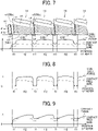
- FIG. 7 is a schematic view of the liquid discharge heads 14 and the suction wiper 41, and a graph illustrating a contact force and a contact pressure of the suction wiper 41 according to a first embodiment of the present disclosure.
- the suction wiper 41 moves in the movement direction C (one of the sheet width directions B), thereby performing the cleaning operation while a contact portion 41b of the suction wiper 41 contacts the nozzle surface 55 from a first end e1 toward a second end e2 of each liquid discharge head 14.
- the contact portion 41b of the suction wiper 41 may be damaged and deteriorated.
- the contact force (pressing force) of the suction wiper 41 with each liquid discharge head 14 is relatively small when the contact portion 41b of the suction wiper 41 passes through one of the first end e1 and the second end e2 intersecting the movement direction C (i.e., the intersecting ends). That is, as illustrated in FIG.
- the contact force of the contact portion 41b of the suction wiper 41 contacting one of the first end e1 and the second end e2 (intersecting ends) of the liquid discharge head 14 in movement ranges H1 is smaller than the contact force of the contact portion 41b of the suction wiper 41 contacting a portion of the liquid discharge head 14 other than the first end e1 and the second end e2 in movement ranges H2.
- the contact force of the suction wiper 41 is relatively small, so that the contact pressure of the suction wiper 41 with the liquid discharge head 14 can be relatively small.
- the contact pressure of the contact portion 41b of the suction wiper 41 contacting one of the first end e1 and the second end e2 (intersecting ends) of the liquid discharge head 14 in movement ranges H1 is smaller than the contact pressure of the contact portion 41b of the suction wiper 41 contacting a portion of the liquid discharge head 14 other than the first end e1 and the second end e2 in movement ranges H2.
- the contact portion 41b of the suction wiper 41 can be prevented from being damaged and deteriorated when the contact portion 41b of the suction wiper 41 passes through one of the first end e1 and the second end e2, thereby maintaining the cleaning function of the suction wiper 41 for a long time.
- the suction wiper 41 moves in a movement path avoiding corners v1 and v2 having an acute angle among four corners (vertices) v1 to v4 of the nozzle surface 55. If the suction wiper 41 contacts the corners v1 and v2 having the acute angle, the contact with the corners v1 and v2 may cause to accelerate damage and deterioration of the suction wiper 41.
- the movement path of the suction wiper 41 is set so as to avoid the corners v1 and v2 having the acute angle, thereby preventing damage and deterioration of the contact portion 41b of the suction wiper 41 due to contact with the corners v1 and v2 having the acute angle.
- damage and deterioration of the suction wiper 41 can be more effectively suppressed.
- the basic configuration of the suction wiper 41 and the liquid discharge head 14 is the same as that of the above-described embodiment illustrated in FIG. 7 , and a third end e3 (the long side 55b) of each liquid discharge head 14 is oblique with respect to the movement direction C. Accordingly, when the suction wiper 41 moves from the first end e1 to the second end e2 of the liquid discharge head 14, the contact area of the suction wiper 41 with the liquid discharge head 14 progressively increases. For this reason, similarly to the above-described embodiment illustrated in FIG.
- the contact pressure of the suction wiper 41 can be reduced when the contact portion 41b of the suction wiper 41 contacts the third end e3 (long side 55b) of each liquid discharge head 14 extending in the movement direction C.
- the contact force of the suction wiper 41 with the liquid discharge head 14 is set such that the first contact force is smaller than the second contact force and the second contact force is smaller than the contact force of the suction wiper 41 contacting the portion other than the first end e1 and the second end e2 (i.e., the first contact force ⁇ the second contact force ⁇ the contact force with the portion other than the first end e1 and the second end e2).
- the first contact force ⁇ the second contact force ⁇ the contact force with the portion other than the first end e1 and the second end e2 damage and deterioration of the suction wiper 41 can be more effectively suppressed, and the cleaning capability can be improved.
- the contact area of the suction wiper 41 with the liquid discharge head 14 is the same (constant). For this reason, when the contact force of the suction wiper 41 with the liquid discharge head 14 is constant, the contact pressure of the suction wiper 41 can also be kept constant, and thus the change of the suction force of the suction wiper 41 or the wiping action can be prevented. In addition, the cleaning function can be stabilized. Note that the contact pressure of the suction wiper 41 with the liquid discharge head 14 is not limited to being kept constant and may change.
- the position detector 49 includes an encoder 56 in which black and white band patterns are arranged alternately, and an optical sensor 57 including a light emitting unit and a light receiving unit.
- the optical sensor 57 is movable together with the suction wiper 41.
- the controller 53 counts pulse signals to detect the relative movement position of the suction wiper 41.
- the controller 53 drives the contact-separation driver 48 based on the detected relative movement position of the suction wiper 41.
- the contact force of the suction wiper 41 can be reduced at the timing when the suction wiper 41 passes through the first end e1 and the second end e2 of the liquid discharge head 14.
- Each of the liquid discharge heads 14A and 14B includes an energy generator for discharging ink, for example, a piezoelectric actuator such as a piezoelectric element, a thermal actuator utilizing film boiling of liquid using a thermoelectric conversion element such as a thermal resistor, a shape-memory alloy actuator utilizing metallic phase change due to temperature change, an electrostatic actuator utilizing electrostatic force, and the like.
- a piezoelectric actuator such as a piezoelectric element
- a thermal actuator utilizing film boiling of liquid using a thermoelectric conversion element such as a thermal resistor
- a shape-memory alloy actuator utilizing metallic phase change due to temperature change
- an electrostatic actuator utilizing electrostatic force, and the like.
- the liquid discharge heads 14A and 14B move in the main scanning direction (the sheet width directions B) so that the liquid discharge heads 14A and 14B approach the maintenance device 40.
- the blade wiper 37 and the suction wiper 41 move relative to the liquid discharge heads 14A and 14B while contacting the liquid discharge heads 14A and 14B.
- ink adhering to the nozzles of the liquid discharge heads 14A and 14B is removed.
- the present disclosure is preferably applied to a serial-type liquid discharge device.
- damage and deterioration of the suction wiper 41 due to contact of the suction wiper 41 with the intersecting ends can be suppressed, and the cleaning function can be maintained for a long time.
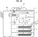
- the image forming apparatus 100 illustrated in FIG. 22 includes the document conveyance device 1, the image reading device 2, the image forming device 3, the sheet feeding device 4, the cartridge mount 5, the sheet ejection portion 7, and the bypass sheet feeding device 8. Note that, in this case, similarly to the image forming device 3 in FIG. 21 , the image forming device 3 in FIG. 22 is disposed facing a sheet conveyance passage 86 in which the sheet P is conveyed in the horizontal direction.
- the sheet P is conveyed in the opposite direction opposite to the sheet conveyance direction, and a first passage changer 74 guides the sheet P to a sheet reverse passage 87. Then, as the sheet P passes the sheet reverse passage 87, the sheet P is reversed from the front face to the back face and conveyed to the image forming device 3 again, so that an image is formed on the back face of the sheet P.
Landscapes
- Ink Jet (AREA)
Abstract
Description
- Aspects of the present disclosure relate to a liquid discharge device and an image forming apparatus.
- There is known an inkjet image forming apparatus that serves as a copier or a printer. The inkjet image forming apparatus discharges ink from a liquid discharge unit to form an image on a sheet. Such an inkjet image forming apparatus includes a cleaner that cleans the liquid discharge unit to satisfactorily maintain the function of the liquid discharge unit (for example,
Japanese Unexamined Patent Application Publication No. 2019-014155 - In general, the cleaner moves relative to the liquid discharge unit while contacting the liquid discharge unit and sucks or wipes liquid remaining in the liquid discharge unit to remove the liquid. At that time, if the cleaner contacts an end of the liquid discharge unit, the cleaner may be damaged or deteriorated.
- To solve the above-described situation, the present disclosure has an object to provide a liquid discharge device that effectively prevents a cleaner from being damaged and deteriorated.
- Embodiments of the present disclosure describe an improved liquid discharge device that includes a liquid discharge unit to discharge a liquid and a cleaner. The liquid discharge unit has a first end, a second end, and a third end extending in a direction intersecting the first end and the second end. The cleaner moves relative to the liquid discharge unit in a movement direction from the first end toward the second end while contacting the liquid discharge unit with a contact force and a contact pressure. The contact force of the cleaner contacting one of the first end and the second end is smaller than the contact force of the cleaner contacting a portion of the liquid discharge unit other than the first end and the second end.
- As a result, according to the present disclosure, the cleaner is effectively prevented from being damaged and deteriorated.
- A more complete appreciation of the disclosure and many of the attendant advantages thereof will be readily obtained as the same becomes better understood by reference to the following detailed description when considered in connection with the accompanying drawings, wherein:
-
FIG. 1 is a schematic view of an image forming apparatus according to embodiments of the present disclosure; -
FIG. 2 is a schematic view of a liquid discharge device according to embodiments of the present disclosure; -
FIG. 3 is a schematic view illustrating a maintenance operation of the liquid discharge device according to embodiments of the present disclosure; -
FIG. 4 is a schematic view illustrating the maintenance operation of the liquid discharge device according to embodiments of the present disclosure; -
FIG. 5 is a schematic view illustrating the maintenance operation of the liquid discharge device according to embodiments of the present disclosure; -
FIG. 6 is a schematic view illustrating the maintenance operation of the liquid discharge device according to embodiments of the present disclosure; -
FIG. 7 is a schematic view of liquid discharge heads of the liquid discharge device and a suction wiper, and a graph illustrating a contact force and a contact pressure of the suction wiper according to a first embodiment of the present disclosure; -
FIG. 8 is a graph illustrating the contact force and the contact pressure of the suction wiper according to a second embodiment of the present disclosure; -
FIG. 9 is a graph illustrating the contact force and the contact pressure of the suction wiper according to a third embodiment of the present disclosure; -
FIG. 10 is a graph illustrating the contact force and the contact pressure of the suction wiper according to a fourth embodiment of the present disclosure; -
FIG. 11 is a schematic view of the liquid discharge heads and the suction wiper, and a graph illustrating the contact force and the contact pressure of the suction wiper according to a fifth embodiment of the present disclosure; -
FIG. 12 is a schematic view of the liquid discharge heads and the suction wiper, and a graph illustrating the contact force and the contact pressure of the suction wiper according to a sixth embodiment of the present disclosure; -
FIG. 13 is a schematic view of the liquid discharge heads and the suction wiper, illustrating an example in which a contact area of the suction wiper with the liquid discharge heads progressively decreases; -
FIG. 14 is a schematic view of the liquid discharge heads and the suction wipers, and a graph illustrating the contact force and the contact pressure of the suction wipers according to a seventh embodiment of the present disclosure; -
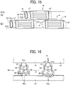
FIG. 15 is a schematic view of the liquid discharge heads and the suction wipers according to an eighth embodiment of the present disclosure; -
FIG. 16 is a schematic view illustrating an example of a contact-force changer according to embodiments of the present disclosure; -
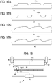
FIGS. 17A to 17D are schematic views illustrating of examples of a guide portion according to embodiments of the present disclosure; -
FIG. 18 is a schematic view illustrating another example of the contact-force changer according to embodiments of the present disclosure; -
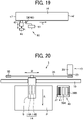
FIG. 19 is a schematic view illustrating yet another example of the contact-force changer according to embodiments of the present disclosure; -
FIG. 20 is a schematic view of a serial-type liquid discharge device according to embodiments of the present disclosure; -
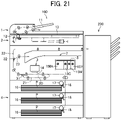
FIG. 21 is a schematic view illustrating another example of the image forming apparatus to which embodiments of the present disclosure can be applied; and -
FIG. 22 is a schematic view illustrating yet another example of the image forming apparatus to which embodiments of the present disclosure can be applied. - The accompanying drawings are intended to depict embodiments of the present disclosure and should not be interpreted to limit the scope thereof. The accompanying drawings are not to be considered as drawn to scale unless explicitly noted. In addition, identical or similar reference numerals designate identical or similar components throughout the several views.
- In describing embodiments illustrated in the drawings, specific terminology is employed for the sake of clarity. However, the disclosure of this patent specification is not intended to be limited to the specific terminology so selected, and it is to be understood that each specific element includes all technical equivalents that have the same function, operate in a similar manner, and achieve a similar result.
- As used herein, the singular forms "a," "an," and "the" are intended to include the plural forms as well, unless the context clearly indicates otherwise.
- It is to be noted that the suffixes Y, M, C, and Bk attached to each reference numeral indicate only that components indicated thereby are used for forming yellow, magenta, cyan, and black images, respectively, and hereinafter may be omitted when color discrimination is not necessary.
- With reference to drawings, descriptions are given below of embodiments of the present disclosure. In the drawings for illustrating embodiments of the present disclosure, elements or components identical or similar in function or shape are given identical reference numerals as far as distinguishable, and redundant descriptions are omitted.
-
FIG. 1 is a schematic view of animage forming apparatus 100 according to an embodiment of the present disclosure. As illustrated inFIG. 1 , theimage forming apparatus 100 according to the present embodiment includes adocument conveyance device 1, animage reading device 2, animage forming device 3, asheet feeding device 4, acartridge mount 5, asheet ejection portion 7, and a bypasssheet feeding device 8. Further, a sheet alignment apparatus (sheet jogger) 200 is disposed adjacent to theimage forming apparatus 100. - The
document conveyance device 1 separates a document one by one from multiple documents on adocument tray 11 and conveys the separated document toward anexposure glass 13 of theimage reading device 2. Thedocument conveyance device 1 includes a plurality of conveyance rollers each functioning as a document conveyor to convey the document. - The
image reading device 2 is an image scanner, in other words, a device to scan an image on a document placed on theexposure glass 13 or an image on a document as the document passes over theexposure glass 13. Theimage reading device 2 includes anoptical scanning unit 12 as an image reading unit. Theoptical scanning unit 12 includes a light source that irradiates a document placed on theexposure glass 13 with light, and a charge-coupled device (CCD) as an image reader that reads an image from the reflected light of the document. Alternatively, a close contact-type image sensor (CIS) may be employed as an image reader. - The
image forming device 3 includes a liquid discharge device that discharges liquid ink onto a sheet to form an image. The liquid discharge device includes aliquid discharge head 14 as a liquid discharge unit. -
Ink cartridges cartridge mount 5. Theink cartridges ink cartridges liquid discharge head 14 by a supply pump. - The
sheet feeding device 4 includes a plurality ofsheet feed trays 16 each functioning as a sheet container. Eachsheet feed tray 16 loads a bundle of sheets P. Each sheet P on which an image is to be formed is a cut sheet which is previously cut in a predetermined size, e.g., A4 size and B4 size, and is contained in thesheet feed tray 16 in a corresponding sheet conveyance direction. Further, eachsheet feed tray 16 includes asheet feed roller 17 that functions as a sheet feeder and asheet separation pad 18 that functions as a sheet separator. As thesheet feed roller 17 rotates, an uppermost sheet P placed on top of the bundle of sheets P contained in thesheet feed tray 16 is fed by thesheet feed roller 17 and thesheet separation pad 18 while the uppermost sheet P is separated from the other sheets of the bundle of sheets. - The bypass
sheet feeding device 8 includes abypass tray 51 and a bypasssheet feed roller 52. Thebypass tray 51 functions as a sheet loader to load a sheet(s) P. The bypasssheet feed roller 52 serves as a sheet feeder to feed the sheet P from thebypass tray 51. Thebypass tray 51 is attached to the body of theimage forming apparatus 100 and is openable and closable with respect to the body of theimage forming apparatus 100. In other words, thebypass tray 51 is swingably attached to the body of theimage forming apparatus 100. When thebypass tray 51 is open (in the state illustrated inFIG. 1 ), a sheet P or a bundle of sheets P can be loaded on thebypass tray 51 to feed the sheet P. - The
sheet alignment apparatus 200 functions as a post-processing apparatus to align and jog the sheets P conveyed from theimage forming apparatus 100. In addition to thesheet alignment apparatus 200, another post-processing apparatus such as a stapling apparatus that staples (binds) the sheets P and a punching apparatus that punches holes in the sheet P may be installed. - With continued reference to
FIG. 1 , a description is given of an operation of theimage forming apparatus 100 according to the present embodiment. As theimage forming apparatus 100 receives an instruction to start a printing operation, the sheet P is fed from thesheet feeding device 4 or the bypasssheet feeding device 8. As the sheet P is conveyed to asheet conveyance passage 80 facing theimage forming device 3, theimage forming device 3 forms an image on the sheet P. Specifically, theliquid discharge head 14 discharges ink to the sheet P based on image data of the document read by theimage reading device 2 or print data transmitted by a terminal device, thereby forming an image on an image formation surface (front face) of the sheet P. Note that the image to be formed on the sheet P may be a meaningful image such as text or a figure, or a pattern that is meaningless. - In the duplex printing, the sheet P is conveyed in the opposite direction opposite to the sheet conveyance direction at a position downstream from the
image forming device 3 in the sheet conveyance direction and guided to a sheetreverse passage 81. Specifically, after the trailing end of the sheet P has passed afirst passage changer 71 that is disposed downstream from theimage forming device 3 in the sheet conveyance direction, thefirst passage changer 71 changes the route to the sheetreverse passage 81, and the sheet P is conveyed in the opposite direction. Accordingly, the sheet P is guided to the sheetreverse passage 81. As the sheet P passes through the sheetreverse passage 81, the sheet P is reversed from the front face to the back face and conveyed to theimage forming device 3 again. Then, theimage forming device 3 repeats the same operation performed to the front face of the sheet P, thereby forming an image on the back face of the sheet P. - A
second passage changer 72 is disposed downstream from thefirst passage changer 71. Thesecond passage changer 72 guides the sheet P, on which the image has been formed, selectively to asheet conveyance passage 82 toward the uppersheet ejection portion 7 or to asheet conveyance passage 83 toward the lowersheet ejection portion 7. When the sheet P is guided to thesheet conveyance passage 82 toward the uppersheet ejection portion 7, the sheet P is ejected onto the uppersheet ejection portion 7. On the other hand, when the sheet P is guided to thesheet conveyance passage 83 toward the lowersheet ejection portion 7, athird passage changer 73 guides the sheet P selectively to asheet conveyance passage 84 toward the lowersheet ejection portion 7 or to asheet conveyance passage 85 toward thesheet alignment apparatus 200. - When the sheet P is guided to the
sheet conveyance passage 84 toward the lowersheet ejection portion 7, the sheet P is ejected onto the lowersheet ejection portion 7. On the other hand, when the sheet P is guided to thesheet conveyance passage 85 toward thesheet alignment apparatus 200, the sheet is conveyed to thesheet alignment apparatus 200, and the bundle of sheets P is aligned and stacked. Thus, a series of printing operations is completed. - Next, the configuration of the liquid discharge device according to the present embodiment is described with reference to
FIG. 2 . As illustrated inFIG. 2 , the liquid discharge device (image forming device 3) according to the present embodiment includes multiple liquid discharge heads 14 arranged side by side in sheet width directions B. The sheet width directions B are directions intersecting or perpendicular to a sheet conveyance direction A in which the sheet P is conveyed. Note that the liquid discharge device according to the present embodiment is not limited to a configuration having the multiple liquid discharge heads 14 as illustrated inFIG. 2 , and may have a configuration having one liquid discharge head disposed over the entire sheet width directions B. - Each
liquid discharge head 14 includes a nozzle row 54 (four nozzle rows inFIG. 2 ) in which a plurality of nozzles is arranged. In the present embodiment, when the sheet P is conveyed to theimage forming device 3 and passes through a region facing theimage forming device 3, eachliquid discharge head 14 is controlled in response to a drive signal based on image data to discharge ink. Thus, ink of each color is discharged from eachliquid discharge head 14 onto the sheet P, thereby forming an image corresponding to the image data on the sheet P. As described above, the liquid discharge device according to the present embodiment is a so-called line-type liquid discharge device in which eachliquid discharge head 14 discharges ink without moving relative to the sheet P being conveyed. Note that the liquid discharge device according to the present disclosure is not limited to the line-type liquid discharge device and may be a serial-type liquid discharge device described later in which the liquid discharge head discharges ink while moving in a main scanning direction (sheet width direction). - As illustrated in
FIG. 2 , in the present embodiment, anozzle surface 55 of eachliquid discharge head 14 has a parallelogram shape. Specifically, eachliquid discharge head 14 has thenozzle surface 55 having the parallelogram shape including a pair ofshort sides 55a extending transversely to the sheet width directions B and a pair oflong sides 55b extending in the sheet width directions B. Thenozzle rows 54 on thenozzle surface 55 are arranged parallel to thelong sides 55b of thenozzle surface 55. Further, end portions of thenozzle rows 54 of the adjacent liquid discharge heads 14 are disposed so as to overlap each other as viewed in the sheet conveyance direction A. Thus, ink can be discharged without interrupting an image between the liquid discharge heads 14 adjacent to each other in the sheet width directions B. - In the inkjet image forming device that discharges ink from the liquid discharge head to form an image on a sheet, a maintenance device is generally provided to maintain and recover the function of the liquid discharge head. The maintenance device includes, for example, a cap that covers the nozzle surface of the liquid discharge head and a cleaner that cleans the nozzle surface.
- Hereinafter, a maintenance operation according to the present embodiment is described with reference to
FIGS. 3 to 6 . As illustrated inFIG. 3 , in theimage forming device 3, the posture of theliquid discharge head 14 is switchable between a state of being disposed obliquely with respect to the horizontal direction as illustrated by the solid line inFIG. 3 and a state of being disposed in the horizontal direction (also referred to as a position retracted from the sheet conveyance passage 80) as illustrated by the long dashed double-short dashed line inFIG. 3 . When an image is formed on the sheet P, theliquid discharge head 14 is obliquely disposed and faces thesheet conveyance passage 80. On the other hand, when the image forming operation is finished and the maintenance operation of theliquid discharge head 14 is performed, theliquid discharge head 14 is disposed in the horizontal direction. - When the maintenance operation is performed, as illustrated in
FIG. 4 , amaintenance device 40 approaches theliquid discharge head 14 switched to the horizontal posture. Themaintenance device 40 is included in the liquid discharge device serving as theimage forming device 3. Themaintenance device 40 moves in the horizontal direction (i.e., a movement direction C which is one of the sheet width directions B) to be arranged below the liquid discharge heads 14. Themaintenance device 40 includes asuction wiper 41 as a cleaner that cleans thenozzle surface 55 of theliquid discharge head 14. Thesuction wiper 41 is a tubular member made of an elastic body such as rubber and has asuction port 41a at the tip thereof. Thesuction wiper 41 is mounted on acarriage 42 that reciprocates in the sheet width directions B. When thecarriage 42 moves along aguide rail 43, thesuction wiper 41 moves together with thecarriage 42 in the movement direction C which is one of the sheet width directions B. - Subsequently, as illustrated in
FIG. 5 , theliquid discharge head 14 is lowered and arranged at a position where theliquid discharge head 14 can be cleaned. Alternatively, themaintenance device 40 may be lifted and arranged at a position where theliquid discharge head 14 can be cleaned without lowering theliquid discharge head 14. In this state, as illustrated inFIG. 6 , thesuction wiper 41 moves along theguide rail 43, so that thesuction wiper 41 cleans thenozzle surface 55 of theliquid discharge head 14 while contacting thenozzle surface 55. Specifically, as thesuction wiper 41 moves while contacting thenozzle surface 55, ink remaining in the nozzle (discharge port) is wiped and removed, and the removed ink is sucked and collected from thesuction port 41a of thesuction wiper 41. As a result, a cleaning operation by thesuction wiper 41 is finished. - After the cleaning operation is finished, the
liquid discharge head 14 is covered with the cap to prevent ink discharge failure due to drying. Thereafter, when the image forming operation is performed again, the cap is separated from theliquid discharge head 14, and themaintenance device 40 is moved and retracted from the position facing theliquid discharge head 14 in the horizontal direction. Then, theliquid discharge head 14 is switched to the oblique posture and is ready to form an image. - Here, the
suction wiper 41 is formed of an elastic material such as rubber so that thenozzle surface 55 of theliquid discharge head 14 is not damaged. However, when thesuction wiper 41 performs the cleaning operation, if thesuction wiper 41 contacts an end or a corner of theliquid discharge head 14, thesuction wiper 41 may be damaged or deteriorated due to the contact. Therefore, in the present embodiment, the following measures are taken to suppress damage and deterioration of thesuction wiper 41. -
FIG. 7 is a schematic view of the liquid discharge heads 14 and thesuction wiper 41, and a graph illustrating a contact force and a contact pressure of thesuction wiper 41 according to a first embodiment of the present disclosure. - As illustrated in
FIG. 7 , thesuction wiper 41 according to the present embodiment moves in the movement direction C (one of the sheet width directions B), thereby performing the cleaning operation while acontact portion 41b of thesuction wiper 41 contacts thenozzle surface 55 from a first end e1 toward a second end e2 of eachliquid discharge head 14. At that time, as thecontact portion 41b of thesuction wiper 41 contacts the first end e1 and the second end e2 (short sides 55a) of eachliquid discharge head 14 intersecting the movement direction C, thecontact portion 41b of thesuction wiper 41 may be damaged and deteriorated. In the present specification, the "first end of the liquid discharge head" (also referred to as an "intersecting end") means an end of the liquid discharge head that the cleaner (e.g., the suction wiper 41) starts contacting when the cleaner moves relative to the liquid discharge head while contacting the liquid discharge head, and the "second end of the liquid discharge head" (also referred to as an "intersecting end") means an end of the liquid discharge head that the cleaner finishes contacting when the cleaner moves relative to the liquid discharge head while contacting the liquid discharge head. - In the present embodiment, to suppress such damage and deterioration of the
suction wiper 41, the contact force (pressing force) of thesuction wiper 41 with eachliquid discharge head 14 is relatively small when thecontact portion 41b of thesuction wiper 41 passes through one of the first end e1 and the second end e2 intersecting the movement direction C (i.e., the intersecting ends). That is, as illustrated inFIG. 7 , the contact force of thecontact portion 41b of thesuction wiper 41 contacting one of the first end e1 and the second end e2 (intersecting ends) of theliquid discharge head 14 in movement ranges H1 is smaller than the contact force of thecontact portion 41b of thesuction wiper 41 contacting a portion of theliquid discharge head 14 other than the first end e1 and the second end e2 in movement ranges H2. - As described above, in the present embodiment, when the
contact portion 41b of thesuction wiper 41 is contacting one of the first end e1 and the second end e2 (the intersecting ends), the contact force of thesuction wiper 41 is relatively small, so that the contact pressure of thesuction wiper 41 with theliquid discharge head 14 can be relatively small. In other words, the contact pressure of thecontact portion 41b of thesuction wiper 41 contacting one of the first end e1 and the second end e2 (intersecting ends) of theliquid discharge head 14 in movement ranges H1 is smaller than the contact pressure of thecontact portion 41b of thesuction wiper 41 contacting a portion of theliquid discharge head 14 other than the first end e1 and the second end e2 in movement ranges H2. Accordingly, thecontact portion 41b of thesuction wiper 41 can be prevented from being damaged and deteriorated when thecontact portion 41b of thesuction wiper 41 passes through one of the first end e1 and the second end e2, thereby maintaining the cleaning function of thesuction wiper 41 for a long time. - Further, as illustrated in
FIG. 7 , in the present embodiment, thesuction wiper 41 moves in a movement path avoiding corners v1 and v2 having an acute angle among four corners (vertices) v1 to v4 of thenozzle surface 55. If thesuction wiper 41 contacts the corners v1 and v2 having the acute angle, the contact with the corners v1 and v2 may cause to accelerate damage and deterioration of thesuction wiper 41. Therefore, in the present embodiment, the movement path of thesuction wiper 41 is set so as to avoid the corners v1 and v2 having the acute angle, thereby preventing damage and deterioration of thecontact portion 41b of thesuction wiper 41 due to contact with the corners v1 and v2 having the acute angle. Thus, damage and deterioration of thesuction wiper 41 can be more effectively suppressed. -
FIG. 8 is a graph illustrating the contact force and the contact pressure of thesuction wiper 41 according to a second embodiment of the present disclosure. As illustrated inFIG. 8 , in the present embodiment, when thecontact portion 41b of thesuction wiper 41 contacts the first end e1 and the second end e2 of the liquid discharge heads 14 in the movement ranges H1, the contact force and the contact pressure of thesuction wiper 41 are 0 or substantially 0. - As described above, the contact force and the contact pressure when the
contact portion 41b of thesuction wiper 41 contacts the first end e1 and the second end e2 are set to 0 or substantially 0, so that damage and deterioration of thecontact portion 41b of thesuction wiper 41 can be more effectively suppressed. When the contact force and the contact pressure of thesuction wiper 41 are 0 or substantially 0, thesuction wiper 41 may contact theliquid discharge head 14 without the pressing force or may be separated from theliquid discharge head 14 in a non-contact state as long as there is no influence on the cleaning operation. -
FIG. 9 is a graph illustrating the contact force and the contact pressure of thesuction wiper 41 according to a third embodiment of the present disclosure. As illustrated inFIG. 9 , in the present embodiment, when thecontact portion 41b of thesuction wiper 41 contacts the portion of theliquid discharge head 14 other than the first end e1 and the second end e2 of the liquid discharge heads 14 in the movement ranges H2, the contact force of thesuction wiper 41 progressively increases to keep the contact pressure of thesuction wiper 41 constant. - In the present embodiment, the basic configuration of the
suction wiper 41 and theliquid discharge head 14 is the same as that of the above-described embodiment illustrated inFIG. 7 , and a third end e3 (thelong side 55b) of eachliquid discharge head 14 is oblique with respect to the movement direction C. Accordingly, when thesuction wiper 41 moves from the first end e1 to the second end e2 of theliquid discharge head 14, the contact area of thesuction wiper 41 with theliquid discharge head 14 progressively increases. For this reason, similarly to the above-described embodiment illustrated inFIG. 7 , when the contact force in the movement ranges H2 does not largely change after thecontact portion 41b of thesuction wiper 41 passes through the first end e1 and the second end e2, the contact area of thesuction wiper 41 increases with the movement of thesuction wiper 41, and the contact pressure of thesuction wiper 41 progressively decreases. - On the other hand, in the present embodiment illustrated in
FIG. 9 , while thecontact portion 41b of thesuction wiper 41 contacts the portion of theliquid discharge head 14 other than the first end e1 and the second end e2 of the liquid discharge heads 14 in the movement ranges H2, the contact force of thesuction wiper 41 increases with the movement of thesuction wiper 41. Therefore, in the present embodiment, even if the contact area of thesuction wiper 41 progressively increases, the contact pressure of thesuction wiper 41 can be kept constant. As a result, the change of the suction force of thesuction wiper 41 or the wiping action due to the change of the contact pressure can be prevented, thereby stabilizing the cleaning function. - Further, in the above-described embodiment illustrated in
FIG. 7 , the contact pressure of thesuction wiper 41 decreases with the movement of thesuction wiper 41. Therefore, the contact pressure is set larger than a predetermined reference value in advance to maintain the contact pressure equal to or larger than the reference value. On the other hand, in the present embodiment illustrated inFIG. 9 , the contact pressure can be kept constant, so that the contact pressure of thesuction wiper 41 can be set low overall as compared with the above-described embodiment illustrated inFIG. 7 . Therefore, in the present embodiment, after thecontact portion 41b of thesuction wiper 41 passes through the first end e1 and the second end e2 of the liquid discharge heads 14, the contact pressure of thesuction wiper 41 can be reduced when thecontact portion 41b of thesuction wiper 41 contacts the third end e3 (long side 55b) of eachliquid discharge head 14 extending in the movement direction C. - As described above, in the present embodiment, the contact pressure can be further reduced and kept constant when the
contact portion 41b of thesuction wiper 41 contacts thelong side 55b (third end e3 extending in the movement direction C) of theliquid discharge head 14. Therefore, damage and deterioration of thesuction wiper 41 due to contact with thelong side 55b can be suppressed, and the cleaning function of thesuction wiper 41 can be stabilized. -
FIG. 10 is a graph illustrating the contact force and the contact pressure of thesuction wiper 41 according to a fourth embodiment of the present disclosure. As illustrated inFIG. 10 , in the present embodiment, the contact force and the contact pressure of thesuction wiper 41 with theliquid discharge head 14 in the movement range H2 progressively decrease before thecontact portion 41b of thesuction wiper 41 contacts the second end e2 of theliquid discharge head 14. As described above, in the present embodiment, the contact force and the contact pressure of thesuction wiper 41 progressively decrease to prevent the contact force and the contact pressure from sharply decreasing. As a result, variations in the cleaning function of thesuction wiper 41 due to sharp changes in the contact force and the contact pressure can be suppressed, and the cleaning function can be stabilized. -
FIG. 11 is a schematic view of the liquid discharge heads 14 and thesuction wiper 41, and a graph illustrating the contact force and the contact pressure of thesuction wiper 41 according to a fifth embodiment of the present disclosure. Hereinafter, the contact force of thesuction wiper 41 contacting the first end e1 of the firstliquid discharge head 14 from a state in which thesuction wiper 41 does not contact theliquid discharge head 14 is referred to as a "first contact force (F1 inFIG. 11 )," and the contact force of thesuction wiper 41 moving from the second end e2 of one liquid discharge head 14 (e.g., first liquid discharge unit) to the first end e1 of another liquid discharge head 14 (e.g., second liquid discharge unit) is referred to as a "second contact force (F2 inFIG. 11 )." In the above-described embodiment illustrated inFIG. 7 , the first contact force is set to be the same as the second contact force. On the other hand, in the fifth embodiment illustrated inFIG. 11 , the first contact force is set to be smaller than the second contact force. That is, in the present embodiment, the contact force of thesuction wiper 41 with theliquid discharge head 14 is set such that the first contact force is smaller than the second contact force and the second contact force is smaller than the contact force of thesuction wiper 41 contacting the portion other than the first end e1 and the second end e2 (i.e., the first contact force < the second contact force < the contact force with the portion other than the first end e1 and the second end e2). As a result, damage and deterioration of thesuction wiper 41 can be more effectively suppressed, and the cleaning capability can be improved. -
FIG. 12 is a schematic view of the liquid discharge heads 14 and thesuction wiper 41, and a graph illustrating the contact force and the contact pressure of thesuction wiper 41 according to a sixth embodiment of the present disclosure. Hereinafter, the contact force of thesuction wiper 41 moving from a state in which thesuction wiper 41 contacts the second end e2 of the lastliquid discharge head 14 to a state in which thesuction wiper 41 does not contact theliquid discharge head 14 is referred to as a "third contact force (F3 inFIG. 12 )." In the sixth embodiment illustrated inFIG. 12 , the third contact force is smaller than the second contact force. That is, in the present embodiment, the contact force of thesuction wiper 41 with theliquid discharge head 14 is set such that the third contact force is smaller than the second contact force and the second contact force is smaller than the contact force of thesuction wiper 41 contacting the portion other than the first end e1 and the second end e2 (i.e., the third contact force < the second contact force < the contact force with the portion other than the first end e1 and the second end e2). As a result, damage and deterioration of thesuction wiper 41 can be more effectively suppressed, and the cleaning capability can be improved. - In each of the above-described embodiments illustrated in
FIGS. 7 to 12 , the contact area of thesuction wiper 41 with theliquid discharge head 14 progressively increases as thesuction wiper 41 moves from the first end e1 to the second end e2 of theliquid discharge head 14. In addition, the present disclosure is applicable to a configuration in which the contact area of thesuction wiper 41 with theliquid discharge head 14 progressively decreases. Therefore, as illustrated inFIG. 13 , theliquid discharge head 14 illustrated inFIG. 7 may be arranged so as to be laterally reversed. In this case, as thesuction wiper 41 moves from the first end e1 to the second end e2 of theliquid discharge head 14 in the movement direction C inFIG. 13 , the contact area of thesuction wiper 41 with theliquid discharge head 14 progressively decreases. Also in theliquid discharge head 14 having such a configuration, similarly to each of the above-described embodiments, the contact force or the contact pressure of thesuction wiper 41 contacting one of the first end e1 and the second end e2 of theliquid discharge head 14 is smaller than the contact force or the contact pressure of thesuction wiper 41 contacting the portion other than the first end e1 and the second end e2, thereby suppressing damage and deterioration of thesuction wiper 41. - Next,
FIG. 14 is a schematic view of the liquid discharge heads 14 and thesuction wipers 41, and a graph illustrating the contact force and the contact pressure of thesuction wipers 41 according to a seventh embodiment of the present disclosure. As illustrated inFIG. 14 , in the present embodiment, thenozzle surface 55 of eachliquid discharge head 14 has a rectangular shape. In the present embodiment, the multiple liquid discharge heads 14 are disposed in multiple rows shifted from each other in the sheet conveyance direction A (the direction intersecting the movement direction C of the suction wiper 41), and the multiple liquid discharge heads 14 are shifted from each other in the sheet width directions B (the movement direction C of the suction wiper 41). - Further, in the present embodiment, the
multiple suction wipers 41 are disposed (shifted) corresponding to the multiple rows of the liquid discharge heads 14 in the sheet conveyance direction A, respectively. That is, one of themultiple suction wipers 41 is disposed corresponding to theliquid discharge head 14 in an upper row (a) illustrated inFIG. 14 and, another of themultiple suction wipers 41 is disposed corresponding to theliquid discharge head 14 in a lower row (b) illustrated inFIG. 14 . Note that thesuction wipers 41 and the liquid discharge heads 14 may be arranged in three or more rows. - With such a configuration in the present embodiment, similarly to the above-described embodiments, each
suction wiper 41 moves in the movement direction C to clean thenozzle surface 55 of theliquid discharge head 14 in each row. Also in the present embodiment, when thecontact portion 41b of eachsuction wiper 41 contacts the first end e1 or the second end e2 of eachliquid discharge head 14, the contact with the first end e1 or the second end e2 may cause damage or deterioration of thecontact portion 41b of eachsuction wiper 41. That is, damage and deterioration of thesuction wiper 41 may occur not only in a case in which the first and second ends e1 and e2 of theliquid discharge head 14 are substantially perpendicular to the movement direction C of thesuction wiper 41 as in the above-described embodiments, but also in a case in which the first and second ends e1 and e2 are perpendicular to the movement direction C of thesuction wiper 41. - For this reason, also in the present embodiment, when the
contact portion 41b of eachsuction wiper 41 passes through the first end e1 and the second end e2 of eachliquid discharge head 14, the contact force of eachsuction wiper 41 in the movement ranges H1 is relatively small. Accordingly, similarly to the above-described embodiments, thecontact portion 41b of thesuction wiper 41 can be prevented from being damaged and deteriorated when thecontact portion 41b of thesuction wiper 41 passes through one of the first end e1 and the second end e2, thereby maintaining the cleaning function of thesuction wiper 41 for a long time. In the present embodiment, when thesuction wiper 41 moves from the first end e1 to the second end e2 of theliquid discharge head 14, the contact area of thesuction wiper 41 with theliquid discharge head 14 is the same (constant). For this reason, when the contact force of thesuction wiper 41 with theliquid discharge head 14 is constant, the contact pressure of thesuction wiper 41 can also be kept constant, and thus the change of the suction force of thesuction wiper 41 or the wiping action can be prevented. In addition, the cleaning function can be stabilized. Note that the contact pressure of thesuction wiper 41 with theliquid discharge head 14 is not limited to being kept constant and may change. - Any one of the control methods illustrated in
FIGS. 7 to 10 may be adopted for specific control of the contact pressure of eachsuction wiper 41 in the present embodiment. In the present embodiment, the contact forces of therespective suction wipers 41 are controlled at different timings because therespective suction wipers 41 reach the corresponding liquid discharge heads 14 at the different timings. That is, in the present embodiment, as illustrated in timing charts of the contact forces of the rows (a) and (b) illustrated inFIGS. 14 , first, the contact force of thesuction wiper 41 in the row (b) decreases at the timing when thecontact portion 41b of thesuction wiper 41 in the row (b) reaches the second end e2 of the correspondingliquid discharge head 14, and then the contact force of thesuction wiper 41 in the row (a) decreases at the timing when thecontact portion 41b of thesuction wiper 41 in the row (a) reaches the second end e2 of the correspondingliquid discharge head 14. As described above, in the present embodiment, the contact forces of thesuction wipers 41 change independently at different timings, so that damage and deterioration of thecontact portion 41b of eachsuction wiper 41 can be suppressed. - In an eighth embodiment of the present disclosure illustrated in
FIG. 15 , the relative positions (movement start positions) of therespective suction wipers 41 relative to the corresponding liquid discharge heads 14 are set to be the same. Therefore, the timings when thecontact portions 41b of therespective suction wipers 41 reach the corresponding liquid discharge heads 14 are the same. In this case, the contact forces of therespective suction wipers 41 that contact the corresponding liquid discharge heads 14 can change in synchronization with each other in the rows (a) and (b). - Next, a contact-force changer that changes the contact force of the
suction wiper 41 with theliquid discharge head 14 is described.FIG. 16 is a schematic view of a contact-force changer 50 according to the present embodiment. The contact-force changer 50 illustrated inFIG. 16 includes aholder 44 that holds thesuction wiper 41, aspring 45 as an elastic member that presses thesuction wiper 41, asupport 46 that supports thespring 45, and aguide 47 that guides thesupport 46 along the movement direction C of thesuction wiper 41. Theholder 44 movably holds thesuction wiper 41 toward and away from theliquid discharge head 14. In addition, theholder 44 holds thesuction wiper 41 such that at least thesuction port 41a at the tip of the suction wiper41 projects out of theholder 44 toward theliquid discharge head 14. Thespring 45 is disposed between thesuction wiper 41 and thesupport 46, and an end of thespring 45 opposite to thesuction wiper 41 is supported by thesupport 46. Since thespring 45 is compressed between thesuction wiper 41 and thesupport 46, thesuction wiper 41 is pressed toward theliquid discharge head 14. Thesupport 46 has a plurality ofprojections 46a that contacts theguide 47. In the present embodiment, to stabilize the posture of thesuction wiper 41, thesupport 46 contacts theguide 47 via the plurality ofprojections 46a. That is, thesupport 46 contacts theguide 47 at multiple positions that are not on the same straight line, thereby stabilizing the posture of thesuction wiper 41. - In the contact-
force changer 50 having such a configuration, when thesuction wiper 41 moves to perform the cleaning operation, thesupport 46 is guided along theguide portion 47a of theguide 47. As a result, the end of thespring 45 opposite to the suction wiper 41 (the end adjacent to the support 46) moves toward and away from theliquid discharge head 14, thereby changing a compression amount of thespring 45. That is, when thesupport 46 is guided by theguide portion 47a and moves toward theliquid discharge head 14 as illustrated on the left side inFIG. 16 , the compression amount of thespring 45 increases. On the other hand, when thesupport 46 is guided by theguide portion 47a and moves away from theliquid discharge head 14 as illustrated on the right side inFIG. 16 , the compression amount of thespring 45 decreases. As a result, the contact force of thesuction wiper 41 with theliquid discharge head 14 changes. As illustrated inFIGS. 17A to 17D , theguide portion 47a is formed in a shape following any one of changes of the contact forces illustrated inFIGS. 7 to 10 described above, for example. Accordingly, the contact force of thesuction wiper 41 can be reduced at the first end e1 and the second end e2. As a result, damage and deterioration of thesuction wiper 41 can be suppressed. -
FIG. 18 is a schematic view of the contact-force changer 50 according to another embodiment of the present disclosure. The contact-force changer 50 illustrated inFIG. 18 does not move thesuction wiper 41 toward and away from theliquid discharge head 14. By contrast, the contact-force changer 50 moves theliquid discharge head 14 toward and away from thesuction wiper 41 to change the contact force of thesuction wiper 41 with theliquid discharge head 14. Specifically, the contact-force changer 50 according to the present embodiment includes a contact-separation driver 48 that moves theliquid discharge head 14 toward and away from thesuction wiper 41, aposition detector 49 that detects a relative movement position of thesuction wiper 41 relative to theliquid discharge head 14, and acontroller 53 that controls the contact-separation driver 48 based on a detection signal of theposition detector 49. - The
position detector 49 includes anencoder 56 in which black and white band patterns are arranged alternately, and anoptical sensor 57 including a light emitting unit and a light receiving unit. Theoptical sensor 57 is movable together with thesuction wiper 41. When thesuction wiper 41 moves, the light emitting unit of theoptical sensor 57 irradiates theencoder 56 with light, and the light receiving unit of theoptical sensor 57 receives the light reflected by theencoder 56. At that time, thecontroller 53 counts pulse signals to detect the relative movement position of thesuction wiper 41. Further, thecontroller 53 drives the contact-separation driver 48 based on the detected relative movement position of thesuction wiper 41. As a result, the contact force of thesuction wiper 41 can be reduced at the timing when thesuction wiper 41 passes through the first end e1 and the second end e2 of theliquid discharge head 14. -
FIG. 19 is a schematic view of the contact-force changer 50 according to yet another embodiment of the present disclosure. In the embodiment illustrated inFIG. 19 , thecontroller 53 controls the contact-separation driver 48 that moves thesuction wiper 41 toward and away from theliquid discharge head 14 based on a detection signal of a sensor 58 (position detector 49). Thesensor 58 may be an optical sensor or a magnetic sensor. Instead of thesensor 58, a timer may be used to measure the movement time of thesuction wiper 41, and the relative movement position of thesuction wiper 41 may be acquired based on the measured movement time of thesuction wiper 41. In still another embodiment, the contact-force changer 50 may moves both thesuction wiper 41 and theliquid discharge head 14 toward and away from each other. - Various embodiments of the present disclosure have been described above. The above-described embodiments are illustrative and do not limit the present disclosure. It is therefore to be understood that within the scope of the appended claims, numerous additional modifications and variations are possible to the present disclosure otherwise than as specifically described herein.
- For example, the present disclosure is also applicable to a serial-type liquid discharge device as illustrated in
FIG. 20 . The serial-type liquid discharge device (image forming device 3) illustrated inFIG. 20 includes acarriage 9 on which theliquid discharge head 14 is mounted, a guide (guide rod) 10 that guides thecarriage 9 in the main scanning direction which is the sheet width directions B, and adriver 19 that moves thecarriage 9. - In the present embodiment, the
carriage 9 includes aliquid discharge head 14A for black having a discharge port array for discharging black ink droplets and aliquid discharge head 14B for color having a discharge port array for discharging ink of each color of cyan, magenta, and yellow. In the liquid discharge heads 14A and 14B, the respective discharge port arrays are arranged in a direction intersecting the main scanning direction (i.e., sheet conveyance direction A), and each ink is discharged downward. Note that individual liquid discharge heads may be provided for different colors (e.g., cyan, magenta, and yellow). Alternatively, one liquid discharge head may discharge inks of black and cyan and the other liquid discharge head may discharge inks of magenta and yellow. Further, the color of ink to be used is not limited to the above colors. - Each of the liquid discharge heads 14A and 14B includes an energy generator for discharging ink, for example, a piezoelectric actuator such as a piezoelectric element, a thermal actuator utilizing film boiling of liquid using a thermoelectric conversion element such as a thermal resistor, a shape-memory alloy actuator utilizing metallic phase change due to temperature change, an electrostatic actuator utilizing electrostatic force, and the like.
- In addition, a plurality of sub-tanks for supplying inks of the respective colors to the liquid discharge heads 14A and 14B is mounted on the
carriage 9. The inks are supplied to the sub-tanks fromink cartridges FIG. 1 ) mounted on the body of theimage forming apparatus 100 via ink supply tubes. - The
driver 19 includes amotor 28 serving as a driving source and atiming belt 35 looped around adrive pulley 29 and a drivenpulley 30. As themotor 28 is driven and thedrive pulley 29 is rotated, thetiming belt 35 circumferentially moves. Accordingly, thecarriage 9 coupled to thetiming belt 35 is moved in the main scanning direction (the sheet width directions B) along theguide 10. As the rotation direction of themotor 28 is switched between one direction and the opposite direction, thecarriage 9 reciprocates in the main scanning direction. - As the sheet P is conveyed to the
image forming device 3, each of the liquid discharge heads 14A and 14B discharges ink based on image signals while thecarriage 9 moves in the main scanning direction, thereby forming an image for one line on the sheet P not in motion. Then, the sheet P is conveyed by a predetermined amount in the sheet conveyance direction A inFIG. 20 , and an image for the next line is formed. Subsequently, the conveyance and stop of the sheet P and the reciprocating movement of thecarriage 9 are repeated, and ink is discharged onto the sheet P, thereby forming an entire image. - The serial-type liquid discharge device (image forming device 3) according to the present embodiment includes the
maintenance device 40 that maintains each of the liquid discharge heads 14A and 14B. Themaintenance device 40 includescaps blade wiper 37 that is a blade-shaped cleaner, and thesuction wiper 41 that has the same function described in the above embodiments. - When the maintenance operation is performed, the liquid discharge heads 14A and 14B move in the main scanning direction (the sheet width directions B) so that the liquid discharge heads 14A and 14B approach the
maintenance device 40. As the liquid discharge heads 14A and 14B further move in the main scanning direction, theblade wiper 37 and thesuction wiper 41 move relative to the liquid discharge heads 14A and 14B while contacting the liquid discharge heads 14A and 14B. As a result, ink adhering to the nozzles of the liquid discharge heads 14A and 14B is removed. - Even in such a serial-type liquid discharge device, when the
suction wiper 41 contacts the intersecting ends, which intersect the sheet width direction B, of the liquid discharge heads 14A and 14B during the cleaning operation, thesuction wiper 41 may be damaged or deteriorated. Therefore, the present disclosure is preferably applied to a serial-type liquid discharge device. As the present disclosure is applied to the serial-type liquid discharge device, damage and deterioration of thesuction wiper 41 due to contact of thesuction wiper 41 with the intersecting ends can be suppressed, and the cleaning function can be maintained for a long time. - The damage and deterioration of the cleaner is not limited to the
suction wiper 41. That is, also in theblade wiper 37 illustrated inFIG. 20 , as theblade wiper 37 moves relative to the liquid discharge heads 14A and 14B and contacts the intersecting ends of the liquid discharge heads 14A and 14B, theblade wiper 37 may be damaged or deteriorated. Therefore, even in such ablade wiper 37, the contact force and the contact pressure of theblade wiper 37 contacting the intersecting ends are reduced, thereby suppressing damage and deterioration of theblade wiper 37. - Further, the above-described embodiments of the present disclosure can be applied not only to the
image forming apparatus 100 illustrated inFIG. 1 but also, for example, to image formingapparatuses 100 illustrated inFIGS. 21 and22 . Hereinafter, descriptions are given of other examples of the configuration of theimage forming apparatus 100 to which the present disclosure is applicable. Note that the configuration of theimage forming apparatus 100 is mainly described regarding differences from the above-described embodiments, and the other configurations are basically similar to the configurations of the above-described embodiments. Therefore, descriptions of such similar configurations are omitted below. - Similarly to the above-described embodiments, the
image forming apparatus 100 illustrated inFIG. 21 includes thedocument conveyance device 1, theimage reading device 2, theimage forming device 3, thesheet feeding device 4, thecartridge mount 5, and thesheet ejection portion 7. However, theimage forming apparatus 100 illustrated inFIG. 21 does not include the bypasssheet feeding device 8. Unlike theimage forming device 3 inFIG. 1 , theimage forming device 3 inFIG. 20 is disposed facing asheet conveyance passage 20 in which the sheet P is conveyed in the horizontal direction. - In the
image forming apparatus 100 illustrated inFIG. 21 , as a printing operation starts, the sheet P is supplied from thesheet feeding device 4 and conveyed to theimage forming device 3. As the sheet P is conveyed to theimage forming device 3, ink is discharged from theliquid discharge head 14 onto the sheet P to form an image on the sheet P. - In the duplex printing, after the sheet P has passed the
image forming device 3, the sheet P is conveyed in the opposite direction opposite to the sheet conveyance direction, and afirst passage changer 31 guides the sheet P to a sheetreverse passage 21. Then, as the sheet P passes the sheetreverse passage 21, the sheet P is reversed from the front face to the back face and conveyed to theimage forming device 3 again, and an image is formed on the back face of the sheet P. - A
second passage changer 32 guides the sheet P, on one face or both faces of which the images have been formed, selectively to asheet conveyance passage 23 toward thesheet ejection portion 7 or to asheet conveyance passage 22 toward thesheet alignment apparatus 200. When the sheet P is guided to thesheet conveyance passage 23 toward thesheet ejection portion 7, the sheet P is ejected onto thesheet ejection portion 7. On the other hand, when the sheet P is guided to thesheet conveyance passage 22 toward thesheet alignment apparatus 200, the sheet is conveyed to thesheet alignment apparatus 200, and the bundle of sheets P is aligned and stacked. - Similarly to the
image forming apparatus 100 illustrated inFIG. 1 , theimage forming apparatus 100 illustrated inFIG. 22 includes thedocument conveyance device 1, theimage reading device 2, theimage forming device 3, thesheet feeding device 4, thecartridge mount 5, thesheet ejection portion 7, and the bypasssheet feeding device 8. Note that, in this case, similarly to theimage forming device 3 inFIG. 21 , theimage forming device 3 inFIG. 22 is disposed facing asheet conveyance passage 86 in which the sheet P is conveyed in the horizontal direction. - In the
image forming apparatus 100 illustrated inFIG. 22 , as a printing operation starts, the sheet P is supplied from thesheet feeding device 4 or the bypasssheet feeding device 8, and is conveyed to theimage forming device 3. As the sheet P is conveyed to theimage forming device 3, ink is discharged from theliquid discharge head 14 onto the sheet P to form an image on the sheet P. - In the duplex printing, after the sheet P has passed the
image forming device 3, the sheet P is conveyed in the opposite direction opposite to the sheet conveyance direction, and afirst passage changer 74 guides the sheet P to a sheetreverse passage 87. Then, as the sheet P passes the sheetreverse passage 87, the sheet P is reversed from the front face to the back face and conveyed to theimage forming device 3 again, so that an image is formed on the back face of the sheet P. - A
second passage changer 75 guides the sheet P, on one face or both faces of which the images have been formed, selectively to asheet conveyance passage 88 toward thesheet ejection portion 7 or to asheet conveyance passage 89 toward thesheet alignment apparatus 200. When the sheet P is guided to thesheet conveyance passage 88 toward thesheet ejection portion 7, the sheet P is ejected onto thesheet ejection portion 7. On the other hand, when the sheet P is guided to thesheet conveyance passage 89 toward thesheet alignment apparatus 200, the sheet P is conveyed to thesheet alignment apparatus 200, and the bundle of sheets P is aligned and stacked. - The
image forming apparatus 100 illustrated inFIG. 21 or22 , to which the present disclosure is applied, can attain the same effects as described above. That is, damage and deterioration of the cleaner that cleans theliquid discharge head 14 are suppressed, and the cleaning function can be maintained for a long time. - The present disclosure is not limited to being applied to an inkjet image forming apparatus that discharges ink onto a sheet to form an image on the sheet. The term "liquid discharge device" according to embodiments of the present disclosure includes, in addition to apparatuses to discharge liquid to a material onto which liquid can adhere, apparatuses to discharge liquid into gas (air) or liquid. The "liquid discharge device" may be, for example, an image forming apparatus to form an image on a sheet by discharging ink, or a three-dimensional fabrication apparatus to discharge a fabrication liquid to a powder layer in which powder material is formed in layers to form a three-dimensional fabrication object.
- The "liquid discharge device" according to embodiments of the present disclosure may include devices to feed, convey, and eject the material onto which liquid can adhere. The liquid discharge device may further include a pretreatment apparatus to coat a treatment liquid onto the material, and a post-treatment apparatus to coat a treatment liquid onto the material, onto which the liquid has been discharged. The term "material onto which liquid can adhere" represents a material onto which liquid is at least temporarily adhered, a material onto which liquid is adhered and fixed, or a material into which liquid is adhered to permeate. Specific examples of the "material onto which liquid can adhere" include, but are not limited to, a recording media such as a paper sheet, a resin film, or cloth, an electronic component such as an electronic substrate or a piezoelectric element, and a medium such as layered powder, an organ model, or a testing cell. The "material onto which liquid can adhere" includes any materials onto which liquid is adhered, unless particularly limited. Examples of the "material onto which liquid can adhere" include any materials onto which liquid can adhere even temporarily, such as paper, thread, fiber, fabric, leather, metal, plastic, glass, wood, ceramic, construction materials (e.g., wall paper or floor material), and cloth textile. Examples of the liquid include ink, treatment liquid, DNA sample, resist, pattern material, binder, fabrication liquid, and solution or liquid dispersion containing amino acid, protein, or calcium.
- Examples of the "liquid discharge device" further include a treatment liquid coating apparatus to discharge a treatment liquid to a sheet to coat, with the treatment liquid, a sheet surface to reform the sheet surface and an injection granulation apparatus in which a composition liquid including raw materials dispersed in a solution is discharged through nozzles to granulate fine particles of the raw materials.
Claims (13)
- A liquid discharge device (3) comprising:a liquid discharge unit (14) configured to discharge a liquid, the liquid discharge unit (14) having a first end (e1), a second end (e2), and a third end (e3) extending in a direction intersecting the first end (e1) and the second end (e2); anda cleaner (41) configured to move relative to the liquid discharge unit (14) in a movement direction from the first end (e1) toward the second end (e2) while contacting the liquid discharge unit (14) with a contact force and a contact pressure, the contact force of the cleaner (41) contacting one of the first end (e1) and the second end (e2) being smaller than the contact force of the cleaner (41) contacting a portion of the liquid discharge unit (14) other than the first end (e1) and the second end (e2).
- The liquid discharge device (3) according to claim 1,
wherein the contact pressure of the cleaner (41) contacting one of the first end (e1) and the second end (e2) is smaller than the contact pressure of the cleaner (41) contacting the portion of the liquid discharge unit (14) other than the first end (e1) and the second end (e2). - The liquid discharge device (3) according to claim 1 or 2,
wherein the contact pressure of the cleaner (41) contacting the portion of the liquid discharge unit (14) other than the first end (e1) and the second end (e2) is constant. - The liquid discharge device (3) according to claim 3,
wherein the contact force of the cleaner (41) contacting the third end (e3) increases with increasing a contact area of the cleaner (41) with the liquid discharge unit (14) to keep the contact pressure of the cleaner (41) with the liquid discharge unit (14) constant. - The liquid discharge device (3) according any one of claims 1 to 4,
wherein the contact force of the cleaner (41) with the liquid discharge unit (14) progressively decreases before the cleaner (41) contacts the second end (e2). - The liquid discharge device (3) according to any one of claims 1 to 5,wherein the liquid discharge unit (14) includes multiple liquid discharge units (14) disposed in multiple rows shifted from each other in a direction intersecting the movement direction,wherein the cleaner (41) includes multiple cleaners disposed corresponding to the multiple rows, respectively, andwherein the contact force of the cleaner (41) with the liquid discharge unit (14) changes independently for each of the multiple liquid discharge units (14) or each of the multiple cleaners.
- The liquid discharge device (3) according to any one of claims 1 to 5, wherein the liquid discharge unit (14) includes multiple liquid discharge units (14) disposed in multiple rows shifted from each other in a direction intersecting the movement direction,wherein the cleaner (41) includes multiple cleaners disposed corresponding to the multiple rows, respectively, andwherein the contact force of the cleaner (41) with the liquid discharge unit (14) changes in synchronization with each other for the multiple liquid discharge units (14) and the multiple cleaners.
- The liquid discharge device (3) according to any one of claims 1 to 7, further comprising a contact-force changer (50) configured to move the cleaner (41) toward and away from the liquid discharge unit (14) to change the contact force of the cleaner (41) with the liquid discharge unit (14).
- The liquid discharge device (3) according to any one of claims 1 to 7, further comprising a contact-force changer (50) configured to move the liquid discharge unit (14) toward and away from the cleaner (41) to change the contact force of the cleaner (41) with the liquid discharge unit (14).
- The liquid discharge device (3) according to any one of claims 1 to 7, further comprising a contact-force changer (50) configured to change the contact force of the cleaner (41) with the liquid discharge unit (14), the contact-force changer (50) including:an elastic member (45) configured to press the cleaner (41) toward the liquid discharge unit (14); anda guide (47) configured to guide an end of the elastic member (45) opposite to the cleaner (41) toward and away from the liquid discharge unit (14) along with a relative movement of the cleaner (41) from the first end (e1) to the second end (e2).
- The liquid discharge device (3) according to any one of claims 1 to 7, further comprising:a contact-force changer (50) configured to change the contact force of the cleaner (41) with the liquid discharge unit (14),a position detector (49) configured to detect a relative movement position of the cleaner (41) relative to the liquid discharge unit (14) from the first end (e1) toward the second end (e2), anda contact-separation driver (48) configured to relatively move the cleaner (41) toward or away from the liquid discharge unit (14) based on the relative movement position of the cleaner (41) detected by the position detector (49).
- The liquid discharge device (3) according to claim 1 or 2,wherein the liquid discharge unit (14) includes a first liquid discharge unit (14) and a second liquid discharge unit (14) adjacent to and downstream from the first liquid discharge unit (14) in the movement direction,wherein the contact force of the cleaner (41) contacting the second end (e2) of the first liquid discharge unit (14) and the first end (e1) of the second liquid discharge unit (14) is smaller than the contact force of the cleaner (41) contacting a portion of the liquid discharge unit (14) other than the first end (e1) and the second end (e2) of the first liquid discharge unit (14) and the second liquid discharge unit (14), andwherein the contact force of the cleaner (41) coming into contact with the first end (e1) of the first liquid discharge unit (14) from a state in which the cleaner (41) does not contact the liquid discharge unit (14) is smaller than the contact force of the cleaner (41) contacting the second end (e2) of the first liquid discharge unit (14) and the first end of the second liquid discharge unit (14).
- An image forming apparatus (100) comprising the liquid discharge device (3) according to any one of claims 1 to 12.
Applications Claiming Priority (2)
| Application Number | Priority Date | Filing Date | Title |
|---|---|---|---|
| JP2021022529 | 2021-02-16 | ||
| JP2021158094A JP7759549B2 (en) | 2021-02-16 | 2021-09-28 | Liquid ejection device and image forming device |
Publications (2)
| Publication Number | Publication Date |
|---|---|
| EP4043220A1 true EP4043220A1 (en) | 2022-08-17 |
| EP4043220B1 EP4043220B1 (en) | 2024-06-26 |
Family
ID=80222228
Family Applications (1)
| Application Number | Title | Priority Date | Filing Date |
|---|---|---|---|
| EP22155408.2A Active EP4043220B1 (en) | 2021-02-16 | 2022-02-07 | Liquid discharge device and image forming apparatus |
Country Status (3)
| Country | Link |
|---|---|
| US (1) | US11858271B2 (en) |
| EP (1) | EP4043220B1 (en) |
| CN (1) | CN114940023B (en) |
Families Citing this family (2)
| Publication number | Priority date | Publication date | Assignee | Title |
|---|---|---|---|---|
| JP2023111316A (en) | 2022-01-31 | 2023-08-10 | 株式会社リコー | Liquid ejector |
| JP2024075227A (en) | 2022-11-22 | 2024-06-03 | 株式会社リコー | Liquid ejection device |
Citations (8)
| Publication number | Priority date | Publication date | Assignee | Title |
|---|---|---|---|---|
| US20060098040A1 (en) * | 2004-11-09 | 2006-05-11 | Samsung Electronics Co., Ltd. | Inkjet image forming apparatus comprising a nozzle cleaning unit and method of using the same |
| US20090046122A1 (en) * | 2007-08-17 | 2009-02-19 | Hiroshi Inoue | Maintenance apparatus, liquid ejection apparatus and nozzle surface maintenance method |
| US20120127231A1 (en) * | 2010-11-24 | 2012-05-24 | Brother Kogyo Kabushiki Kaisha | Image recording apparatus |
| US20180126737A1 (en) * | 2016-11-10 | 2018-05-10 | Yukihiro Asano | Head cleaner, maintenance device, and liquid discharge apparatus |
| US20180207936A1 (en) * | 2017-01-25 | 2018-07-26 | Kyocera Document Solutions Inc. | Recording head recovery system, head cleaning mechanism, and inkjet recording apparatus having the same |
| US20180264824A1 (en) * | 2017-03-14 | 2018-09-20 | Kyocera Document Solutions Inc. | Head cleaning mechanism and inkjet recording apparatus including the same |
| JP2019014155A (en) | 2017-07-07 | 2019-01-31 | キヤノン株式会社 | Inkjet recording device |
| US20200282727A1 (en) * | 2019-03-08 | 2020-09-10 | Kyocera Document Solutions Inc. | Recording head maintenance device and inkjet recording apparatus therewith |
Family Cites Families (6)
| Publication number | Priority date | Publication date | Assignee | Title |
|---|---|---|---|---|
| US6241337B1 (en) | 1998-12-28 | 2001-06-05 | Eastman Kodak Company | Ink jet printer with cleaning mechanism having a wiper blade and transducer and method of assembling the printer |
| EP1366907B1 (en) * | 2002-05-24 | 2006-03-29 | Agfa-Gevaert N.V. | Method and apparatus for removing excess ink from inkjet nozzle plates |
| KR20070021427A (en) * | 2005-08-18 | 2007-02-23 | 삼성전자주식회사 | Inkjet image forming apparatus having a cleaning unit |
| JP5239750B2 (en) | 2008-10-31 | 2013-07-17 | 株式会社リコー | Image forming apparatus |
| JP5252293B2 (en) | 2009-02-02 | 2013-07-31 | 株式会社リコー | Recording device |
| JP2012035440A (en) | 2010-08-04 | 2012-02-23 | Ricoh Co Ltd | Image forming apparatus |
-
2022
- 2022-02-07 EP EP22155408.2A patent/EP4043220B1/en active Active
- 2022-02-11 US US17/669,396 patent/US11858271B2/en active Active
- 2022-02-15 CN CN202210136574.6A patent/CN114940023B/en active Active
Patent Citations (8)
| Publication number | Priority date | Publication date | Assignee | Title |
|---|---|---|---|---|
| US20060098040A1 (en) * | 2004-11-09 | 2006-05-11 | Samsung Electronics Co., Ltd. | Inkjet image forming apparatus comprising a nozzle cleaning unit and method of using the same |
| US20090046122A1 (en) * | 2007-08-17 | 2009-02-19 | Hiroshi Inoue | Maintenance apparatus, liquid ejection apparatus and nozzle surface maintenance method |
| US20120127231A1 (en) * | 2010-11-24 | 2012-05-24 | Brother Kogyo Kabushiki Kaisha | Image recording apparatus |
| US20180126737A1 (en) * | 2016-11-10 | 2018-05-10 | Yukihiro Asano | Head cleaner, maintenance device, and liquid discharge apparatus |
| US20180207936A1 (en) * | 2017-01-25 | 2018-07-26 | Kyocera Document Solutions Inc. | Recording head recovery system, head cleaning mechanism, and inkjet recording apparatus having the same |
| US20180264824A1 (en) * | 2017-03-14 | 2018-09-20 | Kyocera Document Solutions Inc. | Head cleaning mechanism and inkjet recording apparatus including the same |
| JP2019014155A (en) | 2017-07-07 | 2019-01-31 | キヤノン株式会社 | Inkjet recording device |
| US20200282727A1 (en) * | 2019-03-08 | 2020-09-10 | Kyocera Document Solutions Inc. | Recording head maintenance device and inkjet recording apparatus therewith |
Also Published As
| Publication number | Publication date |
|---|---|
| US20220258476A1 (en) | 2022-08-18 |
| CN114940023B (en) | 2024-05-17 |
| EP4043220B1 (en) | 2024-06-26 |
| US11858271B2 (en) | 2024-01-02 |
| CN114940023A (en) | 2022-08-26 |
Similar Documents
| Publication | Publication Date | Title |
|---|---|---|
| EP3670195B1 (en) | Inkjet printing apparatus | |
| US8714682B2 (en) | Image forming apparatus | |
| CN110271289B (en) | Liquid ejecting apparatus and method of cleaning liquid ejecting head | |
| US8752953B2 (en) | Image forming apparatus | |
| US8342628B2 (en) | Image forming apparatus | |
| CN102673157B (en) | Fluid ejection device and flushing method | |
| EP4043220B1 (en) | Liquid discharge device and image forming apparatus | |
| US9969169B2 (en) | Liquid discharger and liquid discharger failure detection method | |
| JP2012035440A (en) | Image forming apparatus | |
| US8562090B2 (en) | Image forming apparatus and method for controlling the same | |
| JP2008238531A (en) | Image forming apparatus | |
| US8052246B2 (en) | Recording device and recording medium conveying method | |
| JP6483037B2 (en) | Control method for reducing printhead damage and contamination | |
| US20210245513A1 (en) | Head maintenance device, liquid discharge apparatus, and printer | |
| US9987848B2 (en) | Ink jet recording apparatus and cleaning method thereof | |
| US20110187781A1 (en) | Liquid ejecting apparatus and liquid ejecting method | |
| JP5982856B2 (en) | Liquid ejection device | |
| JP2009262492A (en) | Image forming apparatus | |
| JP7759549B2 (en) | Liquid ejection device and image forming device | |
| JP2013111772A (en) | Reading apparatus and printing apparatus | |
| JP5915405B2 (en) | Image forming apparatus | |
| US20130038650A1 (en) | Image forming apparatus including recording head for ejecting liquid droplets | |
| US11597223B2 (en) | Liquid discharge apparatus | |
| JP2007125882A (en) | Inkjet recording device | |
| US20240326442A1 (en) | Wiping device and liquid discharge apparatus |
Legal Events
| Date | Code | Title | Description |
|---|---|---|---|
| PUAI | Public reference made under article 153(3) epc to a published international application that has entered the european phase |
Free format text: ORIGINAL CODE: 0009012 |
|
| STAA | Information on the status of an ep patent application or granted ep patent |
Free format text: STATUS: REQUEST FOR EXAMINATION WAS MADE |
|
| 17P | Request for examination filed |
Effective date: 20220207 |
|
| AK | Designated contracting states |
Kind code of ref document: A1 Designated state(s): AL AT BE BG CH CY CZ DE DK EE ES FI FR GB GR HR HU IE IS IT LI LT LU LV MC MK MT NL NO PL PT RO RS SE SI SK SM TR |
|
| GRAP | Despatch of communication of intention to grant a patent |
Free format text: ORIGINAL CODE: EPIDOSNIGR1 |
|
| STAA | Information on the status of an ep patent application or granted ep patent |
Free format text: STATUS: GRANT OF PATENT IS INTENDED |
|
| INTG | Intention to grant announced |
Effective date: 20240131 |
|
| P01 | Opt-out of the competence of the unified patent court (upc) registered |
Effective date: 20240319 |
|
| GRAS | Grant fee paid |
Free format text: ORIGINAL CODE: EPIDOSNIGR3 |
|
| GRAA | (expected) grant |
Free format text: ORIGINAL CODE: 0009210 |
|
| STAA | Information on the status of an ep patent application or granted ep patent |
Free format text: STATUS: THE PATENT HAS BEEN GRANTED |
|
| AK | Designated contracting states |
Kind code of ref document: B1 Designated state(s): AL AT BE BG CH CY CZ DE DK EE ES FI FR GB GR HR HU IE IS IT LI LT LU LV MC MK MT NL NO PL PT RO RS SE SI SK SM TR |
|
| REG | Reference to a national code |
Ref country code: GB Ref legal event code: FG4D |
|
| REG | Reference to a national code |
Ref country code: CH Ref legal event code: EP |
|
| REG | Reference to a national code |
Ref country code: DE Ref legal event code: R096 Ref document number: 602022004076 Country of ref document: DE |
|
| PG25 | Lapsed in a contracting state [announced via postgrant information from national office to epo] |
Ref country code: BG Free format text: LAPSE BECAUSE OF FAILURE TO SUBMIT A TRANSLATION OF THE DESCRIPTION OR TO PAY THE FEE WITHIN THE PRESCRIBED TIME-LIMIT Effective date: 20240626 |
|
| PG25 | Lapsed in a contracting state [announced via postgrant information from national office to epo] |
Ref country code: HR Free format text: LAPSE BECAUSE OF FAILURE TO SUBMIT A TRANSLATION OF THE DESCRIPTION OR TO PAY THE FEE WITHIN THE PRESCRIBED TIME-LIMIT Effective date: 20240626 Ref country code: FI Free format text: LAPSE BECAUSE OF FAILURE TO SUBMIT A TRANSLATION OF THE DESCRIPTION OR TO PAY THE FEE WITHIN THE PRESCRIBED TIME-LIMIT Effective date: 20240626 |
|
| REG | Reference to a national code |
Ref country code: LT Ref legal event code: MG9D |
|
| PG25 | Lapsed in a contracting state [announced via postgrant information from national office to epo] |
Ref country code: GR Free format text: LAPSE BECAUSE OF FAILURE TO SUBMIT A TRANSLATION OF THE DESCRIPTION OR TO PAY THE FEE WITHIN THE PRESCRIBED TIME-LIMIT Effective date: 20240927 |
|
| PG25 | Lapsed in a contracting state [announced via postgrant information from national office to epo] |
Ref country code: LV Free format text: LAPSE BECAUSE OF FAILURE TO SUBMIT A TRANSLATION OF THE DESCRIPTION OR TO PAY THE FEE WITHIN THE PRESCRIBED TIME-LIMIT Effective date: 20240626 |
|
| REG | Reference to a national code |
Ref country code: NL Ref legal event code: MP Effective date: 20240626 |
|
| PG25 | Lapsed in a contracting state [announced via postgrant information from national office to epo] |
Ref country code: NO Free format text: LAPSE BECAUSE OF FAILURE TO SUBMIT A TRANSLATION OF THE DESCRIPTION OR TO PAY THE FEE WITHIN THE PRESCRIBED TIME-LIMIT Effective date: 20240926 Ref country code: LV Free format text: LAPSE BECAUSE OF FAILURE TO SUBMIT A TRANSLATION OF THE DESCRIPTION OR TO PAY THE FEE WITHIN THE PRESCRIBED TIME-LIMIT Effective date: 20240626 Ref country code: HR Free format text: LAPSE BECAUSE OF FAILURE TO SUBMIT A TRANSLATION OF THE DESCRIPTION OR TO PAY THE FEE WITHIN THE PRESCRIBED TIME-LIMIT Effective date: 20240626 Ref country code: GR Free format text: LAPSE BECAUSE OF FAILURE TO SUBMIT A TRANSLATION OF THE DESCRIPTION OR TO PAY THE FEE WITHIN THE PRESCRIBED TIME-LIMIT Effective date: 20240927 Ref country code: FI Free format text: LAPSE BECAUSE OF FAILURE TO SUBMIT A TRANSLATION OF THE DESCRIPTION OR TO PAY THE FEE WITHIN THE PRESCRIBED TIME-LIMIT Effective date: 20240626 Ref country code: BG Free format text: LAPSE BECAUSE OF FAILURE TO SUBMIT A TRANSLATION OF THE DESCRIPTION OR TO PAY THE FEE WITHIN THE PRESCRIBED TIME-LIMIT Effective date: 20240626 Ref country code: RS Free format text: LAPSE BECAUSE OF FAILURE TO SUBMIT A TRANSLATION OF THE DESCRIPTION OR TO PAY THE FEE WITHIN THE PRESCRIBED TIME-LIMIT Effective date: 20240926 |
|
| PG25 | Lapsed in a contracting state [announced via postgrant information from national office to epo] |
Ref country code: NL Free format text: LAPSE BECAUSE OF FAILURE TO SUBMIT A TRANSLATION OF THE DESCRIPTION OR TO PAY THE FEE WITHIN THE PRESCRIBED TIME-LIMIT Effective date: 20240626 |
|
| REG | Reference to a national code |
Ref country code: AT Ref legal event code: MK05 Ref document number: 1697397 Country of ref document: AT Kind code of ref document: T Effective date: 20240626 |
|
| PG25 | Lapsed in a contracting state [announced via postgrant information from national office to epo] |
Ref country code: NL Free format text: LAPSE BECAUSE OF FAILURE TO SUBMIT A TRANSLATION OF THE DESCRIPTION OR TO PAY THE FEE WITHIN THE PRESCRIBED TIME-LIMIT Effective date: 20240626 |
|
| PG25 | Lapsed in a contracting state [announced via postgrant information from national office to epo] |
Ref country code: PT Free format text: LAPSE BECAUSE OF FAILURE TO SUBMIT A TRANSLATION OF THE DESCRIPTION OR TO PAY THE FEE WITHIN THE PRESCRIBED TIME-LIMIT Effective date: 20241028 |
|
| PG25 | Lapsed in a contracting state [announced via postgrant information from national office to epo] |
Ref country code: PT Free format text: LAPSE BECAUSE OF FAILURE TO SUBMIT A TRANSLATION OF THE DESCRIPTION OR TO PAY THE FEE WITHIN THE PRESCRIBED TIME-LIMIT Effective date: 20241028 |
|
| PG25 | Lapsed in a contracting state [announced via postgrant information from national office to epo] |
Ref country code: PL Free format text: LAPSE BECAUSE OF FAILURE TO SUBMIT A TRANSLATION OF THE DESCRIPTION OR TO PAY THE FEE WITHIN THE PRESCRIBED TIME-LIMIT Effective date: 20240626 |
|
| PG25 | Lapsed in a contracting state [announced via postgrant information from national office to epo] |
Ref country code: EE Free format text: LAPSE BECAUSE OF FAILURE TO SUBMIT A TRANSLATION OF THE DESCRIPTION OR TO PAY THE FEE WITHIN THE PRESCRIBED TIME-LIMIT Effective date: 20240626 |
|
| PG25 | Lapsed in a contracting state [announced via postgrant information from national office to epo] |
Ref country code: IS Free format text: LAPSE BECAUSE OF FAILURE TO SUBMIT A TRANSLATION OF THE DESCRIPTION OR TO PAY THE FEE WITHIN THE PRESCRIBED TIME-LIMIT Effective date: 20241026 Ref country code: AT Free format text: LAPSE BECAUSE OF FAILURE TO SUBMIT A TRANSLATION OF THE DESCRIPTION OR TO PAY THE FEE WITHIN THE PRESCRIBED TIME-LIMIT Effective date: 20240626 |
|
| PG25 | Lapsed in a contracting state [announced via postgrant information from national office to epo] |
Ref country code: CZ Free format text: LAPSE BECAUSE OF FAILURE TO SUBMIT A TRANSLATION OF THE DESCRIPTION OR TO PAY THE FEE WITHIN THE PRESCRIBED TIME-LIMIT Effective date: 20240626 |
|
| PG25 | Lapsed in a contracting state [announced via postgrant information from national office to epo] |
Ref country code: SK Free format text: LAPSE BECAUSE OF FAILURE TO SUBMIT A TRANSLATION OF THE DESCRIPTION OR TO PAY THE FEE WITHIN THE PRESCRIBED TIME-LIMIT Effective date: 20240626 Ref country code: RO Free format text: LAPSE BECAUSE OF FAILURE TO SUBMIT A TRANSLATION OF THE DESCRIPTION OR TO PAY THE FEE WITHIN THE PRESCRIBED TIME-LIMIT Effective date: 20240626 |
|
| PG25 | Lapsed in a contracting state [announced via postgrant information from national office to epo] |
Ref country code: SM Free format text: LAPSE BECAUSE OF FAILURE TO SUBMIT A TRANSLATION OF THE DESCRIPTION OR TO PAY THE FEE WITHIN THE PRESCRIBED TIME-LIMIT Effective date: 20240626 Ref country code: ES Free format text: LAPSE BECAUSE OF FAILURE TO SUBMIT A TRANSLATION OF THE DESCRIPTION OR TO PAY THE FEE WITHIN THE PRESCRIBED TIME-LIMIT Effective date: 20240626 |
|
| PG25 | Lapsed in a contracting state [announced via postgrant information from national office to epo] |
Ref country code: SM Free format text: LAPSE BECAUSE OF FAILURE TO SUBMIT A TRANSLATION OF THE DESCRIPTION OR TO PAY THE FEE WITHIN THE PRESCRIBED TIME-LIMIT Effective date: 20240626 Ref country code: SK Free format text: LAPSE BECAUSE OF FAILURE TO SUBMIT A TRANSLATION OF THE DESCRIPTION OR TO PAY THE FEE WITHIN THE PRESCRIBED TIME-LIMIT Effective date: 20240626 Ref country code: RO Free format text: LAPSE BECAUSE OF FAILURE TO SUBMIT A TRANSLATION OF THE DESCRIPTION OR TO PAY THE FEE WITHIN THE PRESCRIBED TIME-LIMIT Effective date: 20240626 Ref country code: PL Free format text: LAPSE BECAUSE OF FAILURE TO SUBMIT A TRANSLATION OF THE DESCRIPTION OR TO PAY THE FEE WITHIN THE PRESCRIBED TIME-LIMIT Effective date: 20240626 Ref country code: IS Free format text: LAPSE BECAUSE OF FAILURE TO SUBMIT A TRANSLATION OF THE DESCRIPTION OR TO PAY THE FEE WITHIN THE PRESCRIBED TIME-LIMIT Effective date: 20241026 Ref country code: ES Free format text: LAPSE BECAUSE OF FAILURE TO SUBMIT A TRANSLATION OF THE DESCRIPTION OR TO PAY THE FEE WITHIN THE PRESCRIBED TIME-LIMIT Effective date: 20240626 Ref country code: EE Free format text: LAPSE BECAUSE OF FAILURE TO SUBMIT A TRANSLATION OF THE DESCRIPTION OR TO PAY THE FEE WITHIN THE PRESCRIBED TIME-LIMIT Effective date: 20240626 Ref country code: CZ Free format text: LAPSE BECAUSE OF FAILURE TO SUBMIT A TRANSLATION OF THE DESCRIPTION OR TO PAY THE FEE WITHIN THE PRESCRIBED TIME-LIMIT Effective date: 20240626 Ref country code: AT Free format text: LAPSE BECAUSE OF FAILURE TO SUBMIT A TRANSLATION OF THE DESCRIPTION OR TO PAY THE FEE WITHIN THE PRESCRIBED TIME-LIMIT Effective date: 20240626 |
|
| PG25 | Lapsed in a contracting state [announced via postgrant information from national office to epo] |
Ref country code: IT Free format text: LAPSE BECAUSE OF FAILURE TO SUBMIT A TRANSLATION OF THE DESCRIPTION OR TO PAY THE FEE WITHIN THE PRESCRIBED TIME-LIMIT Effective date: 20240626 |
|
| REG | Reference to a national code |
Ref country code: DE Ref legal event code: R097 Ref document number: 602022004076 Country of ref document: DE |
|
| PG25 | Lapsed in a contracting state [announced via postgrant information from national office to epo] |
Ref country code: DK Free format text: LAPSE BECAUSE OF FAILURE TO SUBMIT A TRANSLATION OF THE DESCRIPTION OR TO PAY THE FEE WITHIN THE PRESCRIBED TIME-LIMIT Effective date: 20240626 |
|
| PLBE | No opposition filed within time limit |
Free format text: ORIGINAL CODE: 0009261 |
|
| STAA | Information on the status of an ep patent application or granted ep patent |
Free format text: STATUS: NO OPPOSITION FILED WITHIN TIME LIMIT |
|
| 26N | No opposition filed |
Effective date: 20250327 |
|
| PG25 | Lapsed in a contracting state [announced via postgrant information from national office to epo] |
Ref country code: SE Free format text: LAPSE BECAUSE OF FAILURE TO SUBMIT A TRANSLATION OF THE DESCRIPTION OR TO PAY THE FEE WITHIN THE PRESCRIBED TIME-LIMIT Effective date: 20240626 |
|
| PG25 | Lapsed in a contracting state [announced via postgrant information from national office to epo] |
Ref country code: MC Free format text: LAPSE BECAUSE OF FAILURE TO SUBMIT A TRANSLATION OF THE DESCRIPTION OR TO PAY THE FEE WITHIN THE PRESCRIBED TIME-LIMIT Effective date: 20240626 |
|
| REG | Reference to a national code |
Ref country code: CH Ref legal event code: PL |
|
| PG25 | Lapsed in a contracting state [announced via postgrant information from national office to epo] |
Ref country code: LU Free format text: LAPSE BECAUSE OF NON-PAYMENT OF DUE FEES Effective date: 20250207 |
|
| PG25 | Lapsed in a contracting state [announced via postgrant information from national office to epo] |
Ref country code: CH Free format text: LAPSE BECAUSE OF NON-PAYMENT OF DUE FEES Effective date: 20250228 |
|
| REG | Reference to a national code |
Ref country code: BE Ref legal event code: MM Effective date: 20250228 |
|
| PG25 | Lapsed in a contracting state [announced via postgrant information from national office to epo] |
Ref country code: BE Free format text: LAPSE BECAUSE OF NON-PAYMENT OF DUE FEES Effective date: 20250228 |
|
| PG25 | Lapsed in a contracting state [announced via postgrant information from national office to epo] |
Ref country code: IE Free format text: LAPSE BECAUSE OF NON-PAYMENT OF DUE FEES Effective date: 20250207 |
|
| PGFP | Annual fee paid to national office [announced via postgrant information from national office to epo] |
Ref country code: GB Payment date: 20260220 Year of fee payment: 5 |
|
| PGFP | Annual fee paid to national office [announced via postgrant information from national office to epo] |
Ref country code: DE Payment date: 20260218 Year of fee payment: 5 |
|
| PGFP | Annual fee paid to national office [announced via postgrant information from national office to epo] |
Ref country code: FR Payment date: 20260219 Year of fee payment: 5 |