EP4043119A1 - Bending work system and greasing unit - Google Patents
Bending work system and greasing unit Download PDFInfo
- Publication number
- EP4043119A1 EP4043119A1 EP20873680.1A EP20873680A EP4043119A1 EP 4043119 A1 EP4043119 A1 EP 4043119A1 EP 20873680 A EP20873680 A EP 20873680A EP 4043119 A1 EP4043119 A1 EP 4043119A1
- Authority
- EP
- European Patent Office
- Prior art keywords
- tool
- greasing
- greasing unit
- sliding contact
- unit
- Prior art date
- Legal status (The legal status is an assumption and is not a legal conclusion. Google has not performed a legal analysis and makes no representation as to the accuracy of the status listed.)
- Granted
Links
Images





Classifications
-
- B—PERFORMING OPERATIONS; TRANSPORTING
- B21—MECHANICAL METAL-WORKING WITHOUT ESSENTIALLY REMOVING MATERIAL; PUNCHING METAL
- B21D—WORKING OR PROCESSING OF SHEET METAL OR METAL TUBES, RODS OR PROFILES WITHOUT ESSENTIALLY REMOVING MATERIAL; PUNCHING METAL
- B21D37/00—Tools as parts of machines covered by this subclass
- B21D37/18—Lubricating, e.g. lubricating tool and workpiece simultaneously
-
- B—PERFORMING OPERATIONS; TRANSPORTING
- B21—MECHANICAL METAL-WORKING WITHOUT ESSENTIALLY REMOVING MATERIAL; PUNCHING METAL
- B21D—WORKING OR PROCESSING OF SHEET METAL OR METAL TUBES, RODS OR PROFILES WITHOUT ESSENTIALLY REMOVING MATERIAL; PUNCHING METAL
- B21D37/00—Tools as parts of machines covered by this subclass
- B21D37/04—Movable or exchangeable mountings for tools
-
- B—PERFORMING OPERATIONS; TRANSPORTING
- B21—MECHANICAL METAL-WORKING WITHOUT ESSENTIALLY REMOVING MATERIAL; PUNCHING METAL
- B21D—WORKING OR PROCESSING OF SHEET METAL OR METAL TUBES, RODS OR PROFILES WITHOUT ESSENTIALLY REMOVING MATERIAL; PUNCHING METAL
- B21D5/00—Bending sheet metal along straight lines, e.g. to form simple curves
- B21D5/02—Bending sheet metal along straight lines, e.g. to form simple curves on press brakes without making use of clamping means
-
- B—PERFORMING OPERATIONS; TRANSPORTING
- B21—MECHANICAL METAL-WORKING WITHOUT ESSENTIALLY REMOVING MATERIAL; PUNCHING METAL
- B21D—WORKING OR PROCESSING OF SHEET METAL OR METAL TUBES, RODS OR PROFILES WITHOUT ESSENTIALLY REMOVING MATERIAL; PUNCHING METAL
- B21D5/00—Bending sheet metal along straight lines, e.g. to form simple curves
- B21D5/02—Bending sheet metal along straight lines, e.g. to form simple curves on press brakes without making use of clamping means
- B21D5/0209—Tools therefor
- B21D5/0236—Tool clamping
-
- B—PERFORMING OPERATIONS; TRANSPORTING
- B21—MECHANICAL METAL-WORKING WITHOUT ESSENTIALLY REMOVING MATERIAL; PUNCHING METAL
- B21D—WORKING OR PROCESSING OF SHEET METAL OR METAL TUBES, RODS OR PROFILES WITHOUT ESSENTIALLY REMOVING MATERIAL; PUNCHING METAL
- B21D5/00—Bending sheet metal along straight lines, e.g. to form simple curves
- B21D5/02—Bending sheet metal along straight lines, e.g. to form simple curves on press brakes without making use of clamping means
- B21D5/0209—Tools therefor
- B21D5/0254—Tool exchanging
-
- F—MECHANICAL ENGINEERING; LIGHTING; HEATING; WEAPONS; BLASTING
- F16—ENGINEERING ELEMENTS AND UNITS; GENERAL MEASURES FOR PRODUCING AND MAINTAINING EFFECTIVE FUNCTIONING OF MACHINES OR INSTALLATIONS; THERMAL INSULATION IN GENERAL
- F16N—LUBRICATING
- F16N1/00—Constructional modifications of parts of machines or apparatus for the purpose of lubrication
-
- F—MECHANICAL ENGINEERING; LIGHTING; HEATING; WEAPONS; BLASTING
- F16—ENGINEERING ELEMENTS AND UNITS; GENERAL MEASURES FOR PRODUCING AND MAINTAINING EFFECTIVE FUNCTIONING OF MACHINES OR INSTALLATIONS; THERMAL INSULATION IN GENERAL
- F16N—LUBRICATING
- F16N11/00—Arrangements for supplying grease from a stationary reservoir or the equivalent in or on the machine or member to be lubricated; Grease cups
-
- F—MECHANICAL ENGINEERING; LIGHTING; HEATING; WEAPONS; BLASTING
- F16—ENGINEERING ELEMENTS AND UNITS; GENERAL MEASURES FOR PRODUCING AND MAINTAINING EFFECTIVE FUNCTIONING OF MACHINES OR INSTALLATIONS; THERMAL INSULATION IN GENERAL
- F16N—LUBRICATING
- F16N11/00—Arrangements for supplying grease from a stationary reservoir or the equivalent in or on the machine or member to be lubricated; Grease cups
- F16N11/08—Arrangements for supplying grease from a stationary reservoir or the equivalent in or on the machine or member to be lubricated; Grease cups with mechanical drive, other than directly by springs or weights
-
- Y—GENERAL TAGGING OF NEW TECHNOLOGICAL DEVELOPMENTS; GENERAL TAGGING OF CROSS-SECTIONAL TECHNOLOGIES SPANNING OVER SEVERAL SECTIONS OF THE IPC; TECHNICAL SUBJECTS COVERED BY FORMER USPC CROSS-REFERENCE ART COLLECTIONS [XRACs] AND DIGESTS
- Y10—TECHNICAL SUBJECTS COVERED BY FORMER USPC
- Y10T—TECHNICAL SUBJECTS COVERED BY FORMER US CLASSIFICATION
- Y10T483/00—Tool changing
- Y10T483/17—Tool changing including machine tool or component
- Y10T483/1729—Reciprocating tool machine tool [e.g., broaching machine, shaping machine, etc.]
- Y10T483/1731—Reciprocating tool machine tool [e.g., broaching machine, shaping machine, etc.] including matrix
Definitions
- the present disclosure relates to a bending system for bending a plate-shaped workpiece, and a greasing unit for suppling grease to a sliding contact part that is a part of a tool holder of a press brake and is in sliding contact with the tool.
- a bending system includes a tool storage that is arranged on a side of a press brake and stores a plurality of tools.
- the tool storage includes a plurality of stockers that retain the plurality of tools, and a certain selected stocker is configured to be able to be positioned at a change position for changing the tool.
- the bending system includes a tool change unit that changes the tool with respect to the tool holder and the stocker positioned at the change position of the press brake, and the tool change unit is provided on the back side of a table of the press brake so that it can be moved in the left-right direction.
- the tool change unit includes a tool retention member that retains the tool by being engaged with an engagement hole of the tool.
- the bending system includes a servo motor as a moving actuator that moves the tool change unit in the left-right direction (see Patent Literature 1 and Patent Literature 2).
- Patent Literature 3 there is a prior art related to the present disclosure shown in Patent Literature 3, in addition to the ones shown in Patent Literature 1 and Patent Literature 2.
- An object of the present disclosure is to provide a bending system and a greasing unit that enable easy application of grease to a sliding contact part of a tool holder while suppressing variation in a grease application state.
- a bending system that includes a greasing unit configured to move in a left-right direction by way of a moving operation of an external operation member and to supply grease to a sliding contact part that is a part of a tool holder of a press brake and is in sliding contact with a tool, and a greasing unit holder provided on one side in a left-right direction of a table of the press brake and configured to support the greasing unit,
- the greasing unit includes a greasing unit main body, and an application member provided on the greasing unit main body and formed in a shape corresponding to the sliding contact part of the tool holder, the application member being configured to be able to be impregnated with the grease and configured to apply the grease to the sliding contact part of the tool holder.
- the greasing unit holder is moved, by way of the moving operation of the external operation member, to one side in the left-right direction of the table from the other side in the left-right direction of the table or from the one side in the left-right direction of the table to the other side in the left-right direction of the table.
- the grease can be easily applied to the sliding contact part of the tool holder while suppressing variation in a grease application state.
- a greasing unit that includes a greasing unit main body and an application member provided on the greasing unit main body and formed in a shape corresponding to a sliding contact part, the sliding contact part being a part of a tool holder of a press brake and being in sliding contact with a tool, the application member being configured to be able to be impregnated with grease and configured to apply the grease to the sliding contact part of the tool holder.
- the greasing unit holder is moved from one side in the left-right direction of a table of the press brake to the other side in the left-right direction of the table, or is moved from the other side in the left-right direction of the table of the press brake to the one side in the left-right direction of the table.
- the grease can be easily applied to the sliding contact part of the tool holder while suppressing variation in a grease application state.
- the "left-right direction” is one of the horizontal directions and refers to a lateral direction of the press brake.
- the "front-back direction” is a horizontal direction orthogonal to the left-right direction, and refers to a depth direction of the press brake.
- the “tool” is meant to include an upper tool and a lower tool.
- FF indicates the forward direction
- FR indicates the backward direction
- L indicates the left direction
- R indicates the right direction
- U indicates the upward direction
- D indicates the downward direction.
- a bending system 10 is a system for bending a plate-shaped workpiece (sheet metal) W by using a punch tool 12 as an upper tool and a die tool 14 as a lower tool, both of which are automatically changeable.
- an engagement hole 12h is formed through the central portion in the lateral direction of the punch tool 12, and an engagement groove 12g for drop prevention is formed at a shank 12s as a base portion of the punch tool 12 (see Figure 2 ).
- An engagement hole 14h is formed through the central portion in the lateral direction of the die tool 14 (see Figure 2 ).
- the engagement hole 12h of the punch tool 12 and the engagement hole 14h of the die tool 14 are each shown in a circular hole shape, but the shape thereof is not limited to the circular hole shape and may be an elongated hole shape.
- the bending system 10 includes a press brake 16 that bends the workpiece W by the cooperation of the punch tool 12 and the die tool 14. First, the configuration of the press brake 16 will be specifically described.
- the press brake 16 includes a main frame 18, and the main frame 18 includes a pair of side plates 20 that are separated and opposed to each other in the left-right direction, and a plurality of connecting members 22 that connect the pair of side plates 20. Further, a lower table 24 extending in the left-right direction is provided on the lower part of the main frame 18. An upper table 26 extending in the left-right direction is provided on the upper part of the main frame 18 so as to be vertically movable. A hydraulic cylinder 28 is provided on the upper part of each of the side plates 20 as a vertically moving actuator for vertically moving the upper table 26. Note that instead of configuring the upper table 26 so as to be vertically movable, the lower table 24 may be configured to be vertically movable. Instead of the hydraulic cylinder 28, a servo motor (not shown) may be used as the vertically moving actuator.
- each of the upper tool holders 30 has a known configuration, for example, shown in Patent Literature 3 and includes a holder main body 34. On the front side of each of the holder main bodies 34, a front clamp plate 36 that clamps the shank 12s of the punch tool 12 is provided so as to be swingable. On the lower end side thereof, each of the front clamp plates 36 includes a pawl 36c that can be engaged with the engagement groove 12g for preventing the punch tool 12 from dropping.
- each of the holder main bodies 34 a rear clamp plate 38 that clamps the shank 12s of the punch tool 12 whose front and back sides are inverted is provided so as to be swingable.
- each of the rear clamp plates 38 includes a pawl 38c that can be engaged with the engagement groove 12g for preventing the punch tool 12 from dropping.
- a lower end surface 34u of each of the holder main bodies 34, a front surface 34f on the lower end side thereof, a rear surface 34r on the lower end side thereof, a rear surface 36r on the lower end side of each of the front clamp plates 36, and a front surface 38f on the lower end side of each of the rear clamp plates 38 are sliding contact parts that are in sliding contact with the punch tool 12 in the upper tool holder 30.
- clamping operations and unclamping operations of the plurality of front clamp plates 36 are respectively performed in synchronization with each other. Therefore, even when the front clamp plate 36 unclamps the punch tool 12, the punch tool 12 does not drop from the upper tool holder 30.
- clamping operations and unclamping operations of the plurality of rear clamp plates 38 are respectively performed in synchronization with each other. Therefore, even when the rear clamp plate 38 unclamps the punch tool 12, the punch tool 12 does not drop from the upper tool holder 30.
- a lower tool holder 40 that retains the die tool 14 so as to be installable and removable is provided on the upper side of the lower table 24, and the lower tool holder 40 extends in the left-right direction.
- the lower tool holder 40 has a known configuration, for example, shown in Patent Literature 1, and a holder groove 40g for causing a shank 14s of the die tool 14 to be inserted into is formed along the left-right direction thereof.
- the lower tool holder 40 includes a clamper 42 that fixes (presses) the shank 14s of the die tool 14.
- the inner surface of the holder groove 40g of the lower tool holder 40 is a sliding contact part that is in sliding contact with the die tool 14 in the lower tool holder 40.
- an upper joint block 44 extending in the left-right direction is provided on the right side portion of the upper table 26.
- a joint groove 44g for causing the shank 12s of the punch tool 12 to be inserted into is formed along the left-right direction thereof.
- the joint grooves 44g of the upper joint block 44 are each arranged in series along the left-right direction in a gap between the holder main body 34 and the front clamp plate 36 in the plurality of upper tool holders 30.
- the inner surface of the joint groove 44g of the upper joint block 44 is a sliding contact part that is in sliding contact with the punch tool 12 in the upper joint block 44.
- the sliding contact part of the upper joint block 44 is formed in a shape similar to that of the sliding contact part of each of the upper tool holders 30.
- a lower joint block 46 extending in the left-right direction is provided on the right side portion of the lower table 24.
- a joint groove 46g for causing the shank 14s of the die tool 14 to be inserted into is formed along the left-right direction thereof.
- the joint groove 46g of the lower joint block 46 is connected to the holder groove 40g of the lower tool holder 40.
- the inner surface of the joint groove 46g of the lower joint block 46 is a sliding contact part that is in sliding contact with the die tool 14 in the lower joint block 46.
- the sliding contact part of the lower joint block 46 is formed in a shape similar to that of the sliding contact part of the lower tool holder 40.
- a tool storage 48 that stores a plurality of punch tools 12 and a plurality of die tools 14 is arranged.
- the tool storage 48 has the same configuration as the known configuration, for example, shown in Patent Literature 1 and Patent Literature 2.
- the configuration of the tool storage 48 will be briefly described as follows.
- the tool storage 48 includes a plurality of upper stockers 50 (only one is shown) that retain the plurality of punch tools 12. Although only the upper stocker 50 positioned at an upper change position for changing the punch tool 12 is shown, the plurality of upper stockers 50 are arranged along the front-rear direction. A certain selected upper stocker 50 is configured to be able to be positioned at the upper change position by an upper stocker moving mechanism (not shown).
- the tool storage 48 includes a plurality of lower stockers 52 (only one is shown) that retain the plurality of die tools 14. Although only the lower stocker 52 positioned at a lower change position for changing the die tool 14 is shown, the plurality of lower stockers 52 are arranged along the front-rear direction. A certain selected lower stocker 52 is configured to be able to be positioned at the lower change position by a lower stocker moving mechanism (not shown).
- an upper beam member 54 extending in the left-right direction is provided via a plurality of brackets 56 (only one is shown).
- an upper guide rail 58 extending in the left-right direction is provided on the back surface (rear surface) of the upper beam member 54.
- a pair of upper tool change units 60 which change the punch tools 12 with respect to the plurality of upper tool holders 30, and the upper stocker 50 positioned at the upper change position are provided so as to be movable in the left-right direction.
- the pair of upper tool change units 60 are provided on the back side of the upper table 26 via the upper beam member 54 and the upper guide rail 58 so as to be movable in the left-right direction.
- Each of the upper tool change units 60 transports the punch tool 12 between the upper tool holder 30 and the upper stocker 50 positioned at the upper change position.
- the pair of upper tool change units 60 may be distinguished and referred to as the first upper tool change unit 60 and the second upper tool change unit 60.
- Each of the upper tool change units 60 has the same configuration as the known configuration shown in Patent Literature 1.
- Each of the upper tool change units 60 includes an upper unit main body 62 provided on the upper guide rail 58 so as to be movable in the left-right direction, and an upper support member 64 provided on the upper unit main body 62 so as to be movable in the front-rear direction.
- Each of the upper support members 64 moves in the front-rear direction with respect to each of the upper unit main bodies 62 by way of driving of an air cylinder 66 as a front-rear moving actuator provided at an appropriate position of each of the upper unit main bodies 62.
- the upper support member 64 may be configured to be vertically movable with respect to the upper unit main body 62.
- Each of the upper tool change units 60 includes an upper tool retention member 68 provided on each of the upper support members 64 so as to be movable in the front-rear direction, and each of the upper tool retention members 68 retains the punch tool 12 by being engaged with the engagement hole 12h of the punch tool 12.
- the distal end side of each of the upper tool retention members 68 is shown as a round-bar shape, but the shape thereof is not limited to the round-bar shape and may be a hook shape.
- Each of the upper tool retention members 68 moves in the front-rear direction with respect to each of the upper support members 64 by way of driving of an air cylinder 70 as another front-rear moving actuator provided at an appropriate position of each of the upper support members 64.
- a servo motor 72 as a left-right moving actuator for moving each of the upper tool change units 60 in the left-right direction is provided at an appropriate position of each of the upper unit main bodies 62. Further, each of the servo motors 72 includes an encoder 74 as a position detector for detecting a position in the left-right direction of each of the upper tool change units 60 (each of the upper tool retention members 68).
- a lower beam member 76 extending in the left-right direction is provided via a plurality of brackets 78 (only one is shown).
- a lower guide rail 80 extending in the left-right direction is provided on the back surface of the lower beam member 76.
- a pair of lower tool change units 82 which change the die tools 14 with respect to the plurality of lower tool holders 40 and the lower stocker 52 positioned at the lower change position, are provided so as to be movable in the left-right direction.
- the pair of lower tool change units 82 are provided on the back side of the lower table 24 via the lower beam member 76 and the lower guide rail 80 so as to be movable in the left-right direction.
- Each of the lower tool change units 82 transports the die tool 14 between the lower tool holder 40 and the lower stocker 52 positioned at the lower change position.
- Each of the lower tool change unit 82 has the same configuration as the known configuration shown in Patent Literature 1.
- Each of the lower tool change units 82 includes a lower unit main body 84 provided on the lower guide rail 80 so as to be movable in the left-right direction, and a lower support member 86 provided on the lower unit main body 84 so as to be movable in the front-rear direction and vertically.
- Each of the lower support members 86 moves in the front-rear direction with respect to each of the lower unit main bodies 84 by way of driving of an air cylinder 88 as a front-rear moving actuator provided at an appropriate position of each of the lower unit main bodies 84.
- Each of the lower support members 86 vertically moves with respect to each of the lower unit main bodies 84 by way of driving of an air cylinder 90 as a vertical moving actuator provided at an appropriate position of each of the lower unit main bodies 84.
- Each of the lower tool change units 82 includes a lower tool retention member 92 provided on each of the lower support members 86 so as to be movable in the front-rear direction, and each of the lower tool retention members 92 retains the die tool 14 by being engaged with the engagement hole 14h of the die tool 14.
- the distal end side of each of the lower tool retention members 92 is shown as a round-bar shape, but the shape thereof is not limited to the round-bar shape and may be a hook shape.
- Each of the lower tool retention members 92 moves in the front-rear direction with respect to each of the lower support members 86 by way of driving of an air cylinder 94 as another front-rear moving actuator provided at an appropriate position of each of the lower support members 86.
- a servo motor 96 as a left-right moving actuator for moving each of the lower tool change units 82 in the left-right direction is provided at an appropriate position of each of the lower unit main bodies 84. Further, each of the servo motors 96 includes an encoder 98 as a position detector for detecting a position in the left-right direction of each of the lower tool change units 82 (each of the lower tool retention members 92).
- the upper tool change unit 60 When the punch tool 12 is transported from the upper tool holder 30 to the upper stocker 50 positioned at the upper change position, the upper tool change unit 60 is moved in the left-right direction by way of driving of the servo motor 72 so that the upper tool retention member 68 is opposed to the engagement hole 12h of the punch tool 12 mounted on the upper tool holder 30. Next, the upper tool retention member 68 is caused to retain the punch tool 12 while the upper tool retention member 68 is being engaged with the engagement hole 12h of the punch tool 12. Then, the upper tool change unit 60 is moved to the right by way of driving of the servo motor 72 so that the punch tool 12 is transported to the right and separated from the upper tool holder 30.
- the upper tool change unit 60 is moved to the right by way of driving of the servo motor 72 so that the punch tool 12 is transported to the right and mounted on the upper stocker 50. After that, the upper tool retention member 68 is separated from the engagement hole 12h of the punch tool 12 so that the retention state of the punch tool 12 caused by the upper tool retention member 68 is released. Note that after the punch tool 12 is separated from the upper tool holder 30, the punch tool 12 may be moved to the back side (rear) of the upper table 26 by the upper tool change unit 60.
- the die tool 14 When the die tool 14 is transported between the lower tool holder 40 and the lower stocker 52 positioned at the lower change position, the same operation as the one described above is performed. As a result, the die tool 14 mounted on the lower tool holder 40 and the die tool 14 mounted on the lower stocker 52 can be automatically changed. Note that when the die tool 14 is installed in or removed from the lower tool holder 40 or the lower stocker 52, the die tool 14 may be vertically moved by the lower tool change unit 82.
- the bending system 10 includes a greasing unit 100 for supplying grease to the sliding contact part of each of the upper tool holders 30 and the sliding contact part of the upper joint block 44.
- the greasing unit 100 moves in the left-right direction by way of a moving operation of the upper tool retention member 68.
- a greasing unit holder 102 that supports the greasing unit 100 is provided via a support arm 104.
- the greasing unit 100 is movable in the left-right direction between a standby position (a position shown by the solid line in Figure 3 ) and a retention change position (a position shown by the alternate long and two short dashes line in Figure 3 ) in the greasing unit holder 102. Then, the specific configuration of the greasing unit 100 will be described as follows.
- the greasing unit 100 includes a greasing unit main body 106, and a grease pool 106s that accommodates the grease is formed in the central part of the greasing unit main body 106.
- An engagement hole 106h for causing each of the upper tool retention members 68 to be engaged with is formed on the back surface (rear surface) of the greasing unit main body 106.
- Each of the upper tool retention members 68 retains the greasing unit 100 by being engaged with the engagement hole 106h of the greasing unit main body 106.
- An application member 108 that applies the grease to the sliding contact part of each of the upper tool holders 30 and the sliding contact part of the upper joint block 44 is provided, via a plurality of attachment members 110 and the like, to the greasing unit main body 106.
- the application member 108 can be installed in and removed from the greasing unit main body 106.
- the application member 108 is made of a porous material such as a polyurethane sponge having open cells, felt, or the like so as to be able to be impregnated with the grease, and a part (lower end portion) of the application member 108 is positioned in the grease pool 106s of the greasing unit main body 106.
- the application member 108 is formed in a shape (an approximate shape) corresponding to the sliding contact part of the upper tool holder 30.
- the application member 108 receives supply of the grease from a grease supply port 102f provided on the greasing unit holder 102.
- the greasing unit 100 is configured such that, when each of the upper tool retention members 68 is inserted into the engagement hole 106h of the greasing unit main body 106, the grease impregnated in the application member 108 is applied to the outer circumferential surface on the distal end side of each of the upper tool retention members 68.
- scrapers 112 that level the grease applied to the sliding contact part of each of the upper tool holders 30 and the sliding contact part of the upper joint block 44 are respectively provided via a plurality of attachment members 114 and the like.
- Each of the scrapers 112 is made of an elastic body such as synthetic rubber. Further, each of the scrapers 112 is formed in a shape (an approximate shape) corresponding to the sliding contact part of the upper tool holder 30, and can be installed in and removed from the greasing unit main body 106.
- the bending system 10 includes a control device 116 that controls the hydraulic cylinder 28 and the like on the basis of a processing program or the like.
- the control device 116 controls each of the upper tool change units 60, each of the servo motors 72, and the like, as described above, on the basis of a tool change program or the like.
- the control device 116 controls each of the upper tool change units 60, each of the servo motors 72, and the like, as will be described later, on the basis of a greasing program or the like.
- the control device 116 is composed of a computer, and includes a memory (not shown) that stores the processing program and the like, and a CPU (not shown) that executes the processing program and the like.
- Each of the encoders 74, each of the encoders 98, and the like are connected to the control device 116.
- the control device 116 monitors a detection result from each of the encoders 74 or each of the encoders 98.
- an operation panel 118 is connected to the control device 116, and the operation panel 118 includes a greasing switch 120 for switching to a greasing mode in which the grease is supplied to the sliding contact part of each of the upper tool holders 30 or the like.
- the control device 116 executes a greasing operation for supplying the grease to the sliding contact part of each of the upper tool holders 30 or the like.
- the greasing operation includes a retention change operation (a grasping change operation) of the greasing unit 100 by the pair of upper tool retention members 68. Then, the specific content of the greasing operation by the control device 116 is as follows.
- the control device 116 controls the first servo motor 72 so that the upper tool retention member 68 of the first upper tool change unit 60 is positioned at the rear side of the engagement hole 106h of the greasing unit 100 that is positioned at the standby position in the greasing unit holder 102.
- the control device 116 controls the first upper tool change unit 60 so that the upper tool retention member 68 of the first upper tool change unit 60 retains the greasing unit 100 by being engaged with the engagement hole 106h of the greasing unit 100.
- the control device 116 controls the first servo motor 72 so that the greasing unit 100 is moved from the standby position and is positioned at the retention change position in the greasing unit holder 102.
- the control device 116 controls the first upper tool change unit 60 and the first servo motor 72 so that the retention state of the greasing unit 100 caused by the upper tool retention member 68 of the first upper tool change unit 60 is released and the first upper tool change unit 60 is separated from the greasing unit 100.
- the control device 116 controls the second servo motor 72 so that the upper tool retention member 68 of the second upper tool change unit 60 is positioned at the rear side of the engagement hole 106h of the greasing unit 100.
- the control device 116 controls the second upper tool change unit 60 so that the upper tool retention member 68 of the second upper tool change unit 60 retains the greasing unit 100 by being engaged with the engagement hole 106h of the greasing unit 100.
- the control device 116 controls each of the upper tool change units 60 and each of the servo motors 72 so that a first retention change operation of the greasing unit 100 is executed by the pair of upper tool retention members 68 at the retention change position in the greasing unit holder 102.
- the control device 116 controls the second servo motor 72 so that the greasing unit 100 exits from the greasing unit holder 102 and is positioned between the greasing unit holder 102 and the leftmost upper tool holder 30.
- the control device 116 controls the second upper tool change unit 60 so that the greasing unit 100 moves backward (moves in the backward direction).
- the control device 116 controls the second servo motor 72 so that the greasing unit 100 moves from the left side of the upper table 26 to the right side of the upper joint block 44 on the back side of the upper table 26.
- the thick dotted arrow in Figure 8 indicates that the greasing unit 100 is moving to the right on the back side of the upper table 26.
- the control device 116 controls the second upper tool change unit 60 so that the greasing unit 100 moves forward (moves in the forward direction) and is opposed to the sliding contact part of the upper joint block 44. Then, the control device 116 controls the second servo motor 72 so that the greasing unit 100 moves from the right side of the upper joint block 44 to the left side of the upper table 26 while the application member 108 is brought into contact with the sliding contact part of the upper tool holder 30 or the sliding contact part of the upper joint block 44 on the lower side of the upper table 26. Further, the control device 116 controls the second servo motor 72 so that the greasing unit 100 makes an entry into the greasing unit holder 102 and is positioned at the retention change position. Note that the circular arrow in Figure 8 indicates that the greasing unit 100 is moving forward. The thick arrow in Figure 8 indicates that the greasing unit 100 is moving to the left on the lower side of the upper table 26.
- the control device 116 controls the second upper tool change unit 60 and the second servo motor 72 so that the greasing unit 100 applies the grease to the sliding contact part of the upper tool holder 30 and the sliding contact part of the upper joint block 44.
- the control device 116 controls the second upper tool change unit 60 and the second servo motor 72 so that the retention state of the greasing unit 100 caused by the upper tool retention member 68 of the second upper tool change unit 60 is released and the second upper tool change unit 60 is separated from the greasing unit 100.
- the control device 116 controls the first servo motor 72 so that the upper tool retention member 68 of the first upper tool change unit 60 is positioned at the rear side of the engagement hole 106h of the greasing unit 100.
- the control device 116 controls the first upper tool change unit 60 so that the upper tool retention member 68 of the first upper tool change unit 60 retains the greasing unit 100 by being engaged with the engagement hole 106h of the greasing unit 100.
- control device 116 controls the first servo motor 72 so that the greasing unit 100 is moved from the retention change position and is positioned at the standby position in the greasing unit holder 102. Then, the control device 116 controls the first upper tool change unit 60 so that the retention state of the greasing unit 100 caused by the upper tool retention member 68 of the first upper tool change unit 60 is released.
- the control device 116 controls each of the upper tool change units 60 and each of the servo motors 72 so that a second retention change operation of the greasing unit 100 is executed by the pair of upper tool retention members 68 at the retention change position in the greasing unit holder 102.
- control device 116 executes the unclamping operation of the plurality of front clamp plates 36 and the plurality of rear clamp plates 38 before executing the greasing operation.
- the control device 116 may control the second upper tool change unit 60 and the second servo motor 72 so that the greasing unit 100 moves from the left side of the upper table 26 to the right side of the upper joint block 44 while the application member 108 is brought into contact with the sliding contact part of the upper tool holder 30 or the sliding contact part of the upper joint block 44.
- the control device 116 controls each of the upper tool change units 60 and each of the servo motors 72 to execute the greasing operation. Therefore, the greasing unit 100 can be moved from the right side of the upper joint block 44 to the left side of the upper table 26 by way of the moving operation of the upper tool retention member 68 of the second upper tool change unit 60 while the application member 108 is brought into contact with the sliding contact part of the upper tool holder 30 or the sliding contact part of the upper joint block 44.
- the grease can be easily applied to the sliding contact part of each of the upper tool holders 30 and the sliding contact part of the upper joint block 44 while suppressing variation in a grease application state.
- the scraper 112 since the grease applied to the sliding contact part of each of the upper tool holders 30 and the sliding contact part of the upper joint block 44 is leveled by the scraper 112, it is possible to sufficiently suppress variation in the grease application state.
- the greasing unit 100 is configured such that the grease impregnated in the application member 108 is applied to the outer circumferential surface on the distal end side of each of the upper tool retention members 68 when each of the upper tool retention members 68 is inserted into the engagement hole 106h of the greasing unit main body 106.
- the control device 116 executes the retention change operation of the greasing unit 100, the grease can be easily applied to each of the upper tool retention members 68.
- the bending system 10 includes another greasing unit 122 for supplying grease to the sliding contact part of each of the upper tool holders 30 and the sliding contact part of the upper joint block 44.
- the greasing unit 122 moves in the left-right direction by way of the moving operation of the upper tool retention member 68.
- a greasing unit holder 124 that supports the greasing unit 122 is provided via a support arm 126.
- the greasing unit 122 is movable in the left-right direction between a standby position (a position shown by the solid line in Figure 9 ) and a retention change position (a position shown by the alternate long and two short dashes line in Figure 9 ) in the greasing unit holder 124. Then, the specific configuration of the greasing unit 122 will be described as follows.
- the greasing unit 122 includes a box-shaped greasing unit main body 128, and a grease pool 128s that accommodates the grease is formed in the greasing unit main body 128.
- An engagement hole 128h for causing each of the upper tool retention members 68 to be engaged with is formed on the back surface (rear surface) of the greasing unit main body 128.
- the greasing unit main body 128 includes a hollow support shaft 130 extending in the front-rear direction at the upper portion thereof, and an inner hole 130h of the support shaft 130 constitutes a part of the engagement hole 128h of the greasing unit main body 128.
- Each of the upper tool retention members 68 retains the greasing unit 122 by being engaged with the engagement hole 128h of the greasing unit main body 128 that includes the inner hole 130h of the support shaft 130.
- a pair of circular application members 132 that apply the grease to the sliding contact part of each of the upper tool holders 30 and the sliding contact part of the upper joint block 44 is provided, via a bearing member 134, a plurality of attachment members 136, and the like, to the support shaft 130 that is a part of the greasing unit main body 128.
- Each of the application members 132 is rotatable around a horizontal shaft center via the bearing member 134 and the like, and can be installed in and removed from the greasing unit main body 106.
- Each of the application members 132 is made of a porous material such as a polyurethane sponge having open cells, felt, or the like so as to be able to be impregnated with the grease, and a part of each of the application members 132 is positioned in the grease pool 128s of the greasing unit main body 128. Further, the pair of application members 132 are each formed in a shape (an approximate shape) corresponding to the sliding contact part of the upper tool holder 30. Each of the application members 132 receives supply of the grease from a grease supply port 124f provided on the greasing unit holder 124.
- the greasing unit 122 is configured such that, when each of the upper tool retention members 68 is inserted into the engagement hole 128h of the greasing unit main body 128, the grease impregnated in one of the application members 132 is applied to the outer circumferential surface on the distal end side of each of the upper tool retention members 68.
- scrapers 138 that level the grease applied to the sliding contact part of each of the upper tool holders 30 and the sliding contact part of the upper joint block 44 are respectively provided via a plurality of attachment members 140 and the like.
- Each of the scrapers 138 is made of an elastic body such as synthetic rubber. Further, each of the scrapers 138 is formed in a shape (an approximate shape) corresponding to the sliding contact part of the upper tool holder 30, and can be installed in and removed from the greasing unit main body 128.
- the control device 116 executes the greasing operation as described above by using the greasing unit 122.
- the greasing operation includes a retention change operation (grasping change operation) of the greasing unit 122 by the pair of upper tool retention members 68.
- an upper tool holder extending in the left-right direction may be used as shown in Patent Literature 1.
- the application member 108 (132) and the scraper 112 (138) are each formed in a shape corresponding to the sliding contact part of the upper tool holder thereof.
- the upper tool change unit 60 (the lower tool change unit 82) on the back side of the upper table 26 (the lower table 24) so as to be movable in the left-right direction
- the upper tool change unit 60 (the lower tool change unit 82) may be provided on the front side of the upper table 26 (the lower table 24) so as to be movable in the left-right direction.
- a moving body provided on the back side or the front side of the upper table 26 so as to be movable in the left-right direction may be used as the external operation member.
- the greasing unit 100 (122) may be moved in the left-right direction by way of a manual operation by an operator.
- another greasing unit having the same configuration as that of the greasing unit 100 (122) may be used to supply grease to the sliding contact part of the lower tool holder 40 and the sliding contact part of the lower joint block 46.
- the scope of rights included in the present disclosure extends not only to the bending system 10 including the greasing unit 100 (122) but also to the greasing unit 100 (122) itself separated from the bending system 10.
Landscapes
- Engineering & Computer Science (AREA)
- Mechanical Engineering (AREA)
- General Engineering & Computer Science (AREA)
- Bending Of Plates, Rods, And Pipes (AREA)
- Mounting, Exchange, And Manufacturing Of Dies (AREA)
Abstract
Description
- The present disclosure relates to a bending system for bending a plate-shaped workpiece, and a greasing unit for suppling grease to a sliding contact part that is a part of a tool holder of a press brake and is in sliding contact with the tool.
- A bending system includes a tool storage that is arranged on a side of a press brake and stores a plurality of tools. The tool storage includes a plurality of stockers that retain the plurality of tools, and a certain selected stocker is configured to be able to be positioned at a change position for changing the tool. In addition, the bending system includes a tool change unit that changes the tool with respect to the tool holder and the stocker positioned at the change position of the press brake, and the tool change unit is provided on the back side of a table of the press brake so that it can be moved in the left-right direction. The tool change unit includes a tool retention member that retains the tool by being engaged with an engagement hole of the tool. The bending system includes a servo motor as a moving actuator that moves the tool change unit in the left-right direction (see
Patent Literature 1 and Patent Literature 2). - It should be noted that there is a prior art related to the present disclosure shown in Patent Literature 3, in addition to the ones shown in
Patent Literature 1 and Patent Literature 2. -
- Patent Literature 1:
Japanese Patent No. 4672868 - Patent Literature 2:
Japanese Patent No. 5947861 - Patent Literature 3:
Japanese Patent No. 5841800 - When the tool is changed by the tool change unit, a part of the tool holder may come into sliding contact with the tool. When there is an increased number of sliding contacts (an increased sliding contact frequency) of the sliding contact part that is a part of the tool holder and is in sliding contact with the tool, the sliding contact part of the tool holder may be worn to the extent that the processing accuracy is affected. On the other hand, in order to suppress the wear of the sliding contact part of the tool holder, it is possible to apply, with a brush, grease to the sliding contact part of the tool holder. However, the grease application work is extremely troublesome and time-consuming, and there is a concern that variation may occur in an application state (an applied surface) of the grease. In other words, there is a problem in that it is difficult to sufficiently prevent the sliding contact part of the tool holder from being worn while simplifying the work of applying the grease to the sliding contact part of the tool holder.
- An object of the present disclosure is to provide a bending system and a greasing unit that enable easy application of grease to a sliding contact part of a tool holder while suppressing variation in a grease application state.
- According to a first aspect of one or more embodiments, there is provided a bending system that includes a greasing unit configured to move in a left-right direction by way of a moving operation of an external operation member and to supply grease to a sliding contact part that is a part of a tool holder of a press brake and is in sliding contact with a tool, and a greasing unit holder provided on one side in a left-right direction of a table of the press brake and configured to support the greasing unit, in which the greasing unit includes a greasing unit main body, and an application member provided on the greasing unit main body and formed in a shape corresponding to the sliding contact part of the tool holder, the application member being configured to be able to be impregnated with the grease and configured to apply the grease to the sliding contact part of the tool holder.
- According to the first aspect, while the application member is brought into contact with the sliding contact part of the tool holder, the greasing unit holder is moved, by way of the moving operation of the external operation member, to one side in the left-right direction of the table from the other side in the left-right direction of the table or from the one side in the left-right direction of the table to the other side in the left-right direction of the table. As a result, the grease can be easily applied to the sliding contact part of the tool holder while suppressing variation in a grease application state.
- According to a second aspect of one or more embodiments, there is provided a greasing unit that includes a greasing unit main body and an application member provided on the greasing unit main body and formed in a shape corresponding to a sliding contact part, the sliding contact part being a part of a tool holder of a press brake and being in sliding contact with a tool, the application member being configured to be able to be impregnated with grease and configured to apply the grease to the sliding contact part of the tool holder.
- According to the second aspect, while the application member is brought into contact with the sliding contact part of the tool holder, the greasing unit holder is moved from one side in the left-right direction of a table of the press brake to the other side in the left-right direction of the table, or is moved from the other side in the left-right direction of the table of the press brake to the one side in the left-right direction of the table. As a result, the grease can be easily applied to the sliding contact part of the tool holder while suppressing variation in a grease application state.
- According to the present embodiment, it is possible to sufficiently prevent the sliding contact part of the tool holder from being worn while simplifying the work of applying the grease to the sliding contact part of the tool holder.
-
- [
Figure 1] Figure 1 is a schematic front view of a bending system according to the present embodiment. - [
Figure 2] Figure 2 is a cross-sectional view taken along the line II-II inFigure 1 . - [
Figure 3] Figure 3 is a schematic enlarged front view in the vicinity of a greasing unit holder that supports a greasing unit according to the present embodiment. - [
Figure 4] Figure 4 is a cross-sectional view showing a state in which grease is supplied to a sliding contact part of an upper tool holder by using the greasing unit according to the present embodiment. - [
Figure 5A] Figure 5A is a right side view of the greasing unit according to the present embodiment. - [
Figure 5B] Figure 5B is a front view of the greasing unit according to the present embodiment. - [
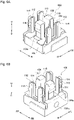
Figure 6A] Figure 6A is a front side perspective view of the greasing unit according to the present embodiment. - [
Figure 6B] Figure 6B is a back side perspective view of the greasing unit according to the present embodiment. - [
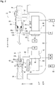
Figure 7] Figure 7 is a control block diagram of the bending system according to the present embodiment. - [
Figure 8] Figure 8 is a diagram illustrating a greasing operation by a control device. - [
Figure 9] Figure 9 is a schematic enlarged front view in the vicinity of a greasing unit holder that supports a greasing unit according to a modification of the present embodiment. - [
Figure 10] Figure 10 is a cross-sectional view showing a state in which grease is supplied to a sliding contact part of an upper tool holder by using the greasing unit according to the modification of the present embodiment. - [
Figure 11A] Figure 11A is a right side view of the greasing unit according to the modification of the present embodiment. - [
Figure 11B] Figure 11B is a side sectional view of the greasing unit according to the modification of the present embodiment. - [
Figure 12A] Figure 12A is a front side perspective view of the greasing unit according to the modification of the present embodiment. - [
Figure 12B] Figure 12B is a back side perspective view of the greasing unit according to the modification of the present embodiment. - Hereinafter, the present embodiment and the modification thereof will be described with reference to
Figures 1 to 12 . - It should be noted that in the description and the claims of the present application, "provided" is meant to include being indirectly provided via another member in addition to being directly provided. The "left-right direction" is one of the horizontal directions and refers to a lateral direction of the press brake. The "front-back direction" is a horizontal direction orthogonal to the left-right direction, and refers to a depth direction of the press brake. The "tool" is meant to include an upper tool and a lower tool. In the drawings, "FF" indicates the forward direction, "FR" indicates the backward direction, "L" indicates the left direction, "R" indicates the right direction, "U" indicates the upward direction, and "D" indicates the downward direction.
- As shown in
Figures 1 and2 , abending system 10 according to the present embodiment is a system for bending a plate-shaped workpiece (sheet metal) W by using apunch tool 12 as an upper tool and adie tool 14 as a lower tool, both of which are automatically changeable. Here, anengagement hole 12h is formed through the central portion in the lateral direction of thepunch tool 12, and anengagement groove 12g for drop prevention is formed at ashank 12s as a base portion of the punch tool 12 (seeFigure 2 ). Anengagement hole 14h is formed through the central portion in the lateral direction of the die tool 14 (seeFigure 2 ). It should be noted that theengagement hole 12h of thepunch tool 12 and theengagement hole 14h of thedie tool 14 are each shown in a circular hole shape, but the shape thereof is not limited to the circular hole shape and may be an elongated hole shape. - The
bending system 10 includes apress brake 16 that bends the workpiece W by the cooperation of thepunch tool 12 and thedie tool 14. First, the configuration of thepress brake 16 will be specifically described. - The
press brake 16 includes amain frame 18, and themain frame 18 includes a pair ofside plates 20 that are separated and opposed to each other in the left-right direction, and a plurality of connectingmembers 22 that connect the pair ofside plates 20. Further, a lower table 24 extending in the left-right direction is provided on the lower part of themain frame 18. An upper table 26 extending in the left-right direction is provided on the upper part of themain frame 18 so as to be vertically movable. Ahydraulic cylinder 28 is provided on the upper part of each of theside plates 20 as a vertically moving actuator for vertically moving the upper table 26. Note that instead of configuring the upper table 26 so as to be vertically movable, the lower table 24 may be configured to be vertically movable. Instead of thehydraulic cylinder 28, a servo motor (not shown) may be used as the vertically moving actuator. - As shown in
Figures 1 to 4 , at the lower end portion of the upper table 26, a plurality ofupper tool holders 30, each of which retains thepunch tool 12 so as to be installable and removable, are provided at intervals in the left-right direction via fixture plates (fastening plates) 32. Each of theupper tool holders 30 has a known configuration, for example, shown in Patent Literature 3 and includes a holdermain body 34. On the front side of each of the holdermain bodies 34, afront clamp plate 36 that clamps theshank 12s of thepunch tool 12 is provided so as to be swingable. On the lower end side thereof, each of thefront clamp plates 36 includes apawl 36c that can be engaged with theengagement groove 12g for preventing thepunch tool 12 from dropping. Further, on the rear side of each of the holdermain bodies 34, arear clamp plate 38 that clamps theshank 12s of thepunch tool 12 whose front and back sides are inverted is provided so as to be swingable. On the lower end side thereof, each of therear clamp plates 38 includes apawl 38c that can be engaged with theengagement groove 12g for preventing thepunch tool 12 from dropping. Here, alower end surface 34u of each of the holdermain bodies 34, afront surface 34f on the lower end side thereof, arear surface 34r on the lower end side thereof, arear surface 36r on the lower end side of each of thefront clamp plates 36, and afront surface 38f on the lower end side of each of therear clamp plates 38 are sliding contact parts that are in sliding contact with thepunch tool 12 in theupper tool holder 30. - It should be noted that clamping operations and unclamping operations of the plurality of
front clamp plates 36 are respectively performed in synchronization with each other. Therefore, even when thefront clamp plate 36 unclamps thepunch tool 12, thepunch tool 12 does not drop from theupper tool holder 30. In the same manner, clamping operations and unclamping operations of the plurality ofrear clamp plates 38 are respectively performed in synchronization with each other. Therefore, even when therear clamp plate 38 unclamps thepunch tool 12, thepunch tool 12 does not drop from theupper tool holder 30. - As shown in
Figures 1 and2 , alower tool holder 40 that retains thedie tool 14 so as to be installable and removable is provided on the upper side of the lower table 24, and thelower tool holder 40 extends in the left-right direction. Thelower tool holder 40 has a known configuration, for example, shown inPatent Literature 1, and aholder groove 40g for causing ashank 14s of thedie tool 14 to be inserted into is formed along the left-right direction thereof. Thelower tool holder 40 includes aclamper 42 that fixes (presses) theshank 14s of thedie tool 14. Here, the inner surface of theholder groove 40g of thelower tool holder 40 is a sliding contact part that is in sliding contact with thedie tool 14 in thelower tool holder 40. - As shown in
Figures 1 and2 , an upperjoint block 44 extending in the left-right direction is provided on the right side portion of the upper table 26. On the upperjoint block 44, ajoint groove 44g for causing theshank 12s of thepunch tool 12 to be inserted into is formed along the left-right direction thereof. Thejoint grooves 44g of the upperjoint block 44 are each arranged in series along the left-right direction in a gap between the holdermain body 34 and thefront clamp plate 36 in the plurality ofupper tool holders 30. Here, the inner surface of thejoint groove 44g of the upperjoint block 44 is a sliding contact part that is in sliding contact with thepunch tool 12 in the upperjoint block 44. The sliding contact part of the upperjoint block 44 is formed in a shape similar to that of the sliding contact part of each of theupper tool holders 30. - As shown in
Figures 1 and2 , a lowerjoint block 46 extending in the left-right direction is provided on the right side portion of the lower table 24. On the lowerjoint block 46, ajoint groove 46g for causing theshank 14s of thedie tool 14 to be inserted into is formed along the left-right direction thereof. Thejoint groove 46g of the lowerjoint block 46 is connected to theholder groove 40g of thelower tool holder 40. Here, the inner surface of thejoint groove 46g of the lowerjoint block 46 is a sliding contact part that is in sliding contact with thedie tool 14 in the lowerjoint block 46. The sliding contact part of the lowerjoint block 46 is formed in a shape similar to that of the sliding contact part of thelower tool holder 40. - As shown in
Figure 1 , on the side in the left-right direction of the press brake 16 (an example of the vicinity of the press brake 16), atool storage 48 that stores a plurality ofpunch tools 12 and a plurality ofdie tools 14 is arranged. Thetool storage 48 has the same configuration as the known configuration, for example, shown inPatent Literature 1 and Patent Literature 2. The configuration of thetool storage 48 will be briefly described as follows. - The
tool storage 48 includes a plurality of upper stockers 50 (only one is shown) that retain the plurality ofpunch tools 12. Although only theupper stocker 50 positioned at an upper change position for changing thepunch tool 12 is shown, the plurality ofupper stockers 50 are arranged along the front-rear direction. A certain selectedupper stocker 50 is configured to be able to be positioned at the upper change position by an upper stocker moving mechanism (not shown). - The
tool storage 48 includes a plurality of lower stockers 52 (only one is shown) that retain the plurality ofdie tools 14. Although only thelower stocker 52 positioned at a lower change position for changing thedie tool 14 is shown, the plurality oflower stockers 52 are arranged along the front-rear direction. A certain selectedlower stocker 52 is configured to be able to be positioned at the lower change position by a lower stocker moving mechanism (not shown). - As shown in
Figure 2 , on the back side (rear side) of the upper table 26, anupper beam member 54 extending in the left-right direction is provided via a plurality of brackets 56 (only one is shown). On the back surface (rear surface) of theupper beam member 54, anupper guide rail 58 extending in the left-right direction is provided. On theupper guide rail 58, a pair of uppertool change units 60, which change thepunch tools 12 with respect to the plurality ofupper tool holders 30, and theupper stocker 50 positioned at the upper change position are provided so as to be movable in the left-right direction. In other words, the pair of uppertool change units 60 are provided on the back side of the upper table 26 via theupper beam member 54 and theupper guide rail 58 so as to be movable in the left-right direction. Each of the uppertool change units 60 transports thepunch tool 12 between theupper tool holder 30 and theupper stocker 50 positioned at the upper change position. Hereinafter, the pair of uppertool change units 60 may be distinguished and referred to as the first uppertool change unit 60 and the second uppertool change unit 60. - Each of the upper
tool change units 60 has the same configuration as the known configuration shown inPatent Literature 1. Each of the uppertool change units 60 includes an upper unitmain body 62 provided on theupper guide rail 58 so as to be movable in the left-right direction, and anupper support member 64 provided on the upper unitmain body 62 so as to be movable in the front-rear direction. Each of theupper support members 64 moves in the front-rear direction with respect to each of the upper unitmain bodies 62 by way of driving of anair cylinder 66 as a front-rear moving actuator provided at an appropriate position of each of the upper unitmain bodies 62. Note that theupper support member 64 may be configured to be vertically movable with respect to the upper unitmain body 62. - Each of the upper
tool change units 60 includes an uppertool retention member 68 provided on each of theupper support members 64 so as to be movable in the front-rear direction, and each of the uppertool retention members 68 retains thepunch tool 12 by being engaged with theengagement hole 12h of thepunch tool 12. The distal end side of each of the uppertool retention members 68 is shown as a round-bar shape, but the shape thereof is not limited to the round-bar shape and may be a hook shape. Each of the uppertool retention members 68 moves in the front-rear direction with respect to each of theupper support members 64 by way of driving of anair cylinder 70 as another front-rear moving actuator provided at an appropriate position of each of theupper support members 64. - A
servo motor 72 as a left-right moving actuator for moving each of the uppertool change units 60 in the left-right direction is provided at an appropriate position of each of the upper unitmain bodies 62. Further, each of theservo motors 72 includes anencoder 74 as a position detector for detecting a position in the left-right direction of each of the upper tool change units 60 (each of the upper tool retention members 68). - On the back side of the lower table 24, a
lower beam member 76 extending in the left-right direction is provided via a plurality of brackets 78 (only one is shown). On the back surface of thelower beam member 76, alower guide rail 80 extending in the left-right direction is provided. On thelower guide rail 80, a pair of lowertool change units 82, which change thedie tools 14 with respect to the plurality oflower tool holders 40 and thelower stocker 52 positioned at the lower change position, are provided so as to be movable in the left-right direction. In other words, the pair of lowertool change units 82 are provided on the back side of the lower table 24 via thelower beam member 76 and thelower guide rail 80 so as to be movable in the left-right direction. Each of the lowertool change units 82 transports thedie tool 14 between thelower tool holder 40 and thelower stocker 52 positioned at the lower change position. - Each of the lower
tool change unit 82 has the same configuration as the known configuration shown inPatent Literature 1. Each of the lowertool change units 82 includes a lower unitmain body 84 provided on thelower guide rail 80 so as to be movable in the left-right direction, and alower support member 86 provided on the lower unitmain body 84 so as to be movable in the front-rear direction and vertically. Each of thelower support members 86 moves in the front-rear direction with respect to each of the lower unitmain bodies 84 by way of driving of anair cylinder 88 as a front-rear moving actuator provided at an appropriate position of each of the lower unitmain bodies 84. Each of thelower support members 86 vertically moves with respect to each of the lower unitmain bodies 84 by way of driving of anair cylinder 90 as a vertical moving actuator provided at an appropriate position of each of the lower unitmain bodies 84. - Each of the lower
tool change units 82 includes a lowertool retention member 92 provided on each of thelower support members 86 so as to be movable in the front-rear direction, and each of the lowertool retention members 92 retains thedie tool 14 by being engaged with theengagement hole 14h of thedie tool 14. The distal end side of each of the lowertool retention members 92 is shown as a round-bar shape, but the shape thereof is not limited to the round-bar shape and may be a hook shape. Each of the lowertool retention members 92 moves in the front-rear direction with respect to each of thelower support members 86 by way of driving of anair cylinder 94 as another front-rear moving actuator provided at an appropriate position of each of thelower support members 86. - A
servo motor 96 as a left-right moving actuator for moving each of the lowertool change units 82 in the left-right direction is provided at an appropriate position of each of the lower unitmain bodies 84. Further, each of theservo motors 96 includes anencoder 98 as a position detector for detecting a position in the left-right direction of each of the lower tool change units 82 (each of the lower tool retention members 92). - Subsequently, an operation related to the automatic change of the punch tool 12 (the die tool 14) will be briefly described.
- When the
punch tool 12 is transported from theupper tool holder 30 to theupper stocker 50 positioned at the upper change position, the uppertool change unit 60 is moved in the left-right direction by way of driving of theservo motor 72 so that the uppertool retention member 68 is opposed to theengagement hole 12h of thepunch tool 12 mounted on theupper tool holder 30. Next, the uppertool retention member 68 is caused to retain thepunch tool 12 while the uppertool retention member 68 is being engaged with theengagement hole 12h of thepunch tool 12. Then, the uppertool change unit 60 is moved to the right by way of driving of theservo motor 72 so that thepunch tool 12 is transported to the right and separated from theupper tool holder 30. Further, the uppertool change unit 60 is moved to the right by way of driving of theservo motor 72 so that thepunch tool 12 is transported to the right and mounted on theupper stocker 50. After that, the uppertool retention member 68 is separated from theengagement hole 12h of thepunch tool 12 so that the retention state of thepunch tool 12 caused by the uppertool retention member 68 is released. Note that after thepunch tool 12 is separated from theupper tool holder 30, thepunch tool 12 may be moved to the back side (rear) of the upper table 26 by the uppertool change unit 60. - When the
punch tool 12 is transported from theupper stocker 50 positioned at the upper change position to theupper tool holder 30, an operation opposite to the above operation is performed. As a result, thepunch tool 12 mounted on theupper tool holder 30 and thepunch tool 12 mounted on theupper stocker 50 can be automatically changed. - When the
die tool 14 is transported between thelower tool holder 40 and thelower stocker 52 positioned at the lower change position, the same operation as the one described above is performed. As a result, thedie tool 14 mounted on thelower tool holder 40 and thedie tool 14 mounted on thelower stocker 52 can be automatically changed. Note that when thedie tool 14 is installed in or removed from thelower tool holder 40 or thelower stocker 52, thedie tool 14 may be vertically moved by the lowertool change unit 82. - Subsequently, a characterizing portion of the
bending system 10 according to the present embodiment will be described. - As shown in
Figures 1 and3 , the bendingsystem 10 includes agreasing unit 100 for supplying grease to the sliding contact part of each of theupper tool holders 30 and the sliding contact part of the upperjoint block 44. Thegreasing unit 100 moves in the left-right direction by way of a moving operation of the uppertool retention member 68. On the left side (one side in the left-right direction) of the upper table 26, agreasing unit holder 102 that supports thegreasing unit 100 is provided via asupport arm 104. Thegreasing unit 100 is movable in the left-right direction between a standby position (a position shown by the solid line inFigure 3 ) and a retention change position (a position shown by the alternate long and two short dashes line inFigure 3 ) in thegreasing unit holder 102. Then, the specific configuration of thegreasing unit 100 will be described as follows. - As shown in
Figures 3 to 6B , thegreasing unit 100 includes a greasing unitmain body 106, and agrease pool 106s that accommodates the grease is formed in the central part of the greasing unitmain body 106. Anengagement hole 106h for causing each of the uppertool retention members 68 to be engaged with is formed on the back surface (rear surface) of the greasing unitmain body 106. Each of the uppertool retention members 68 retains thegreasing unit 100 by being engaged with theengagement hole 106h of the greasing unitmain body 106. - An
application member 108 that applies the grease to the sliding contact part of each of theupper tool holders 30 and the sliding contact part of the upperjoint block 44 is provided, via a plurality ofattachment members 110 and the like, to the greasing unitmain body 106. Theapplication member 108 can be installed in and removed from the greasing unitmain body 106. Theapplication member 108 is made of a porous material such as a polyurethane sponge having open cells, felt, or the like so as to be able to be impregnated with the grease, and a part (lower end portion) of theapplication member 108 is positioned in thegrease pool 106s of the greasing unitmain body 106. Further, theapplication member 108 is formed in a shape (an approximate shape) corresponding to the sliding contact part of theupper tool holder 30. Theapplication member 108 receives supply of the grease from agrease supply port 102f provided on thegreasing unit holder 102. Further, thegreasing unit 100 is configured such that, when each of the uppertool retention members 68 is inserted into theengagement hole 106h of the greasing unitmain body 106, the grease impregnated in theapplication member 108 is applied to the outer circumferential surface on the distal end side of each of the uppertool retention members 68. - On both of the left and right sides of the
application member 108 in the greasing unitmain body 106,scrapers 112 that level the grease applied to the sliding contact part of each of theupper tool holders 30 and the sliding contact part of the upperjoint block 44 are respectively provided via a plurality ofattachment members 114 and the like. Each of thescrapers 112 is made of an elastic body such as synthetic rubber. Further, each of thescrapers 112 is formed in a shape (an approximate shape) corresponding to the sliding contact part of theupper tool holder 30, and can be installed in and removed from the greasing unitmain body 106. - As shown in
Figure 7 , the bendingsystem 10 includes acontrol device 116 that controls thehydraulic cylinder 28 and the like on the basis of a processing program or the like. Thecontrol device 116 controls each of the uppertool change units 60, each of theservo motors 72, and the like, as described above, on the basis of a tool change program or the like. Thecontrol device 116 controls each of the uppertool change units 60, each of theservo motors 72, and the like, as will be described later, on the basis of a greasing program or the like. Thecontrol device 116 is composed of a computer, and includes a memory (not shown) that stores the processing program and the like, and a CPU (not shown) that executes the processing program and the like. - Each of the
encoders 74, each of theencoders 98, and the like are connected to thecontrol device 116. When controlling each of theservo motors 72 or each of theservo motors 96, thecontrol device 116 monitors a detection result from each of theencoders 74 or each of theencoders 98. Further, anoperation panel 118 is connected to thecontrol device 116, and theoperation panel 118 includes a greasing switch 120 for switching to a greasing mode in which the grease is supplied to the sliding contact part of each of theupper tool holders 30 or the like. - When the greasing switch 120 is pressed, the
control device 116 executes a greasing operation for supplying the grease to the sliding contact part of each of theupper tool holders 30 or the like. The greasing operation includes a retention change operation (a grasping change operation) of thegreasing unit 100 by the pair of uppertool retention members 68. Then, the specific content of the greasing operation by thecontrol device 116 is as follows. - As shown in
Figures 3 ,4 , and7 , thecontrol device 116 controls thefirst servo motor 72 so that the uppertool retention member 68 of the first uppertool change unit 60 is positioned at the rear side of theengagement hole 106h of thegreasing unit 100 that is positioned at the standby position in thegreasing unit holder 102. Next, thecontrol device 116 controls the first uppertool change unit 60 so that the uppertool retention member 68 of the first uppertool change unit 60 retains thegreasing unit 100 by being engaged with theengagement hole 106h of thegreasing unit 100. Then, thecontrol device 116 controls thefirst servo motor 72 so that thegreasing unit 100 is moved from the standby position and is positioned at the retention change position in thegreasing unit holder 102. - After that, the
control device 116 controls the first uppertool change unit 60 and thefirst servo motor 72 so that the retention state of thegreasing unit 100 caused by the uppertool retention member 68 of the first uppertool change unit 60 is released and the first uppertool change unit 60 is separated from thegreasing unit 100. Next, thecontrol device 116 controls thesecond servo motor 72 so that the uppertool retention member 68 of the second uppertool change unit 60 is positioned at the rear side of theengagement hole 106h of thegreasing unit 100. Then, thecontrol device 116 controls the second uppertool change unit 60 so that the uppertool retention member 68 of the second uppertool change unit 60 retains thegreasing unit 100 by being engaged with theengagement hole 106h of thegreasing unit 100. - In other words, before the
greasing unit 100 exits from the greasingunit holder 102, thecontrol device 116 controls each of the uppertool change units 60 and each of theservo motors 72 so that a first retention change operation of thegreasing unit 100 is executed by the pair of uppertool retention members 68 at the retention change position in thegreasing unit holder 102. - As shown in
Figures 3 ,4 ,7 , and8 , after the execution of the first retention change operation of thegreasing unit 100, thecontrol device 116 controls thesecond servo motor 72 so that thegreasing unit 100 exits from the greasingunit holder 102 and is positioned between the greasingunit holder 102 and the leftmostupper tool holder 30. Next, thecontrol device 116 controls the second uppertool change unit 60 so that thegreasing unit 100 moves backward (moves in the backward direction). Then, thecontrol device 116 controls thesecond servo motor 72 so that thegreasing unit 100 moves from the left side of the upper table 26 to the right side of the upperjoint block 44 on the back side of the upper table 26. Note that the thick dotted arrow inFigure 8 indicates that thegreasing unit 100 is moving to the right on the back side of the upper table 26. - After that, the
control device 116 controls the second uppertool change unit 60 so that thegreasing unit 100 moves forward (moves in the forward direction) and is opposed to the sliding contact part of the upperjoint block 44. Then, thecontrol device 116 controls thesecond servo motor 72 so that thegreasing unit 100 moves from the right side of the upperjoint block 44 to the left side of the upper table 26 while theapplication member 108 is brought into contact with the sliding contact part of theupper tool holder 30 or the sliding contact part of the upperjoint block 44 on the lower side of the upper table 26. Further, thecontrol device 116 controls thesecond servo motor 72 so that thegreasing unit 100 makes an entry into thegreasing unit holder 102 and is positioned at the retention change position. Note that the circular arrow inFigure 8 indicates that thegreasing unit 100 is moving forward. The thick arrow inFigure 8 indicates that thegreasing unit 100 is moving to the left on the lower side of the upper table 26. - In other words, after the execution of the first retention change operation of the
greasing unit 100, thecontrol device 116 controls the second uppertool change unit 60 and thesecond servo motor 72 so that thegreasing unit 100 applies the grease to the sliding contact part of theupper tool holder 30 and the sliding contact part of the upperjoint block 44. - After the
greasing unit 100 is positioned at the retention change position, thecontrol device 116 controls the second uppertool change unit 60 and thesecond servo motor 72 so that the retention state of thegreasing unit 100 caused by the uppertool retention member 68 of the second uppertool change unit 60 is released and the second uppertool change unit 60 is separated from thegreasing unit 100. Next, thecontrol device 116 controls thefirst servo motor 72 so that the uppertool retention member 68 of the first uppertool change unit 60 is positioned at the rear side of theengagement hole 106h of thegreasing unit 100. Then, thecontrol device 116 controls the first uppertool change unit 60 so that the uppertool retention member 68 of the first uppertool change unit 60 retains thegreasing unit 100 by being engaged with theengagement hole 106h of thegreasing unit 100. - After that, the
control device 116 controls thefirst servo motor 72 so that thegreasing unit 100 is moved from the retention change position and is positioned at the standby position in thegreasing unit holder 102. Then, thecontrol device 116 controls the first uppertool change unit 60 so that the retention state of thegreasing unit 100 caused by the uppertool retention member 68 of the first uppertool change unit 60 is released. - In other words, after the
greasing unit 100 makes an entry from the greasingunit holder 102, thecontrol device 116 controls each of the uppertool change units 60 and each of theservo motors 72 so that a second retention change operation of thegreasing unit 100 is executed by the pair of uppertool retention members 68 at the retention change position in thegreasing unit holder 102. - Note that the
control device 116 executes the unclamping operation of the plurality offront clamp plates 36 and the plurality ofrear clamp plates 38 before executing the greasing operation. Thecontrol device 116 may control the second uppertool change unit 60 and thesecond servo motor 72 so that thegreasing unit 100 moves from the left side of the upper table 26 to the right side of the upperjoint block 44 while theapplication member 108 is brought into contact with the sliding contact part of theupper tool holder 30 or the sliding contact part of the upperjoint block 44. - Subsequently, an action effect of the present embodiment will be described.
- As described above, when the greasing switch 120 is pressed, the
control device 116 controls each of the uppertool change units 60 and each of theservo motors 72 to execute the greasing operation. Therefore, thegreasing unit 100 can be moved from the right side of the upperjoint block 44 to the left side of the upper table 26 by way of the moving operation of the uppertool retention member 68 of the second uppertool change unit 60 while theapplication member 108 is brought into contact with the sliding contact part of theupper tool holder 30 or the sliding contact part of the upperjoint block 44. As a result, the grease can be easily applied to the sliding contact part of each of theupper tool holders 30 and the sliding contact part of the upperjoint block 44 while suppressing variation in a grease application state. Particularly, since the grease applied to the sliding contact part of each of theupper tool holders 30 and the sliding contact part of the upperjoint block 44 is leveled by thescraper 112, it is possible to sufficiently suppress variation in the grease application state. - Further, as described above, the
greasing unit 100 is configured such that the grease impregnated in theapplication member 108 is applied to the outer circumferential surface on the distal end side of each of the uppertool retention members 68 when each of the uppertool retention members 68 is inserted into theengagement hole 106h of the greasing unitmain body 106. As a result, when thecontrol device 116 executes the retention change operation of thegreasing unit 100, the grease can be easily applied to each of the uppertool retention members 68. - Therefore, according to the present embodiment, it is possible to sufficiently prevent the sliding contact part of each of the
upper tool holders 30 and the sliding contact part of the upperjoint block 44 from being worn while simplifying the work of applying the grease to the sliding contact part of each of theupper tool holders 30, the upperjoint block 44, and the outer circumferential surface on the distal end side of each of the uppertool retention members 68. - As shown in
Figures 9 and10 , instead of the greasing unit 100 (seeFigure 1 ), the bendingsystem 10 includes anothergreasing unit 122 for supplying grease to the sliding contact part of each of theupper tool holders 30 and the sliding contact part of the upperjoint block 44. Thegreasing unit 122 moves in the left-right direction by way of the moving operation of the uppertool retention member 68. On the left side (one side in the left-right direction) of the upper table 26, agreasing unit holder 124 that supports thegreasing unit 122 is provided via asupport arm 126. Thegreasing unit 122 is movable in the left-right direction between a standby position (a position shown by the solid line inFigure 9 ) and a retention change position (a position shown by the alternate long and two short dashes line inFigure 9 ) in thegreasing unit holder 124. Then, the specific configuration of thegreasing unit 122 will be described as follows. - As shown in
Figures 11A and 11B , thegreasing unit 122 includes a box-shaped greasing unitmain body 128, and agrease pool 128s that accommodates the grease is formed in the greasing unitmain body 128. Anengagement hole 128h for causing each of the uppertool retention members 68 to be engaged with is formed on the back surface (rear surface) of the greasing unitmain body 128. The greasing unitmain body 128 includes ahollow support shaft 130 extending in the front-rear direction at the upper portion thereof, and aninner hole 130h of thesupport shaft 130 constitutes a part of theengagement hole 128h of the greasing unitmain body 128. Each of the uppertool retention members 68 retains thegreasing unit 122 by being engaged with theengagement hole 128h of the greasing unitmain body 128 that includes theinner hole 130h of thesupport shaft 130. - As shown in
Figures 12A and 12B , a pair ofcircular application members 132 that apply the grease to the sliding contact part of each of theupper tool holders 30 and the sliding contact part of the upperjoint block 44 is provided, via a bearingmember 134, a plurality ofattachment members 136, and the like, to thesupport shaft 130 that is a part of the greasing unitmain body 128. Each of theapplication members 132 is rotatable around a horizontal shaft center via the bearingmember 134 and the like, and can be installed in and removed from the greasing unitmain body 106. Each of theapplication members 132 is made of a porous material such as a polyurethane sponge having open cells, felt, or the like so as to be able to be impregnated with the grease, and a part of each of theapplication members 132 is positioned in thegrease pool 128s of the greasing unitmain body 128. Further, the pair ofapplication members 132 are each formed in a shape (an approximate shape) corresponding to the sliding contact part of theupper tool holder 30. Each of theapplication members 132 receives supply of the grease from agrease supply port 124f provided on thegreasing unit holder 124. Further, thegreasing unit 122 is configured such that, when each of the uppertool retention members 68 is inserted into theengagement hole 128h of the greasing unitmain body 128, the grease impregnated in one of theapplication members 132 is applied to the outer circumferential surface on the distal end side of each of the uppertool retention members 68. - On both of the left and right sides of the
application member 132 in the greasing unitmain body 128,scrapers 138 that level the grease applied to the sliding contact part of each of theupper tool holders 30 and the sliding contact part of the upperjoint block 44 are respectively provided via a plurality ofattachment members 140 and the like. Each of thescrapers 138 is made of an elastic body such as synthetic rubber. Further, each of thescrapers 138 is formed in a shape (an approximate shape) corresponding to the sliding contact part of theupper tool holder 30, and can be installed in and removed from the greasing unitmain body 128. - Note that the control device 116 (see
Figures 6A and 6B ) executes the greasing operation as described above by using thegreasing unit 122. The greasing operation includes a retention change operation (grasping change operation) of thegreasing unit 122 by the pair of uppertool retention members 68. - Then, even in the modification of the present embodiment, the same action effect as that of the above-described present embodiment is exhibited.
- Note that the present disclosure is not limited to the description of the above-described embodiment, and can be implemented in various other aspects by making appropriate changes as follows.
- Instead of the plurality of
upper tool holders 30 arranged at intervals in the left-right direction, an upper tool holder extending in the left-right direction may be used as shown inPatent Literature 1. In this case, the application member 108 (132) and the scraper 112 (138) are each formed in a shape corresponding to the sliding contact part of the upper tool holder thereof. - Instead of providing the upper tool change unit 60 (the lower tool change unit 82) on the back side of the upper table 26 (the lower table 24) so as to be movable in the left-right direction, the upper tool change unit 60 (the lower tool change unit 82) may be provided on the front side of the upper table 26 (the lower table 24) so as to be movable in the left-right direction. In addition, instead of using the upper
tool retention member 68 of the uppertool change unit 60 as an external operation member, a moving body provided on the back side or the front side of the upper table 26 so as to be movable in the left-right direction may be used as the external operation member. Further, instead of moving the greasing unit 100 (122) in the left-right direction by way of the moving operation of the external operation member such as the uppertool retention member 68 of the uppertool change unit 60, the greasing unit 100 (122) may be moved in the left-right direction by way of a manual operation by an operator. - In addition to supplying the grease to the sliding contact part of each of the
upper tool holders 30 and the sliding contact part of the upperjoint block 44, another greasing unit having the same configuration as that of the greasing unit 100 (122) may be used to supply grease to the sliding contact part of thelower tool holder 40 and the sliding contact part of the lowerjoint block 46. - Then, the scope of rights included in the present disclosure extends not only to the
bending system 10 including the greasing unit 100 (122) but also to the greasing unit 100 (122) itself separated from the bendingsystem 10. - The disclosure of the present application is related to the subject matter described in
Japanese Patent Application No. 2019-187798 filed on October 11, 2019
Claims (12)
- A bending system comprising:a greasing unit configured to move in a left-right direction by way of a moving operation of an external operation member and to supply grease to a sliding contact part that is a part of a tool holder of a press brake and is in sliding contact with a tool; anda greasing unit holder provided on one side in a left-right direction of a table of the press brake and configured to support the greasing unit, whereinthe greasing unit includes:a greasing unit main body; andan application member provided on the greasing unit main body and formed in a shape corresponding to the sliding contact part of the tool holder, the application member being configured to be able to be impregnated with grease and configured to apply grease to the sliding contact part of the tool holder.
- The bending system according to Claim 1, further comprising:a tool change unit provided on a back side or a front side of the table so as to be movable in the left-right direction, the tool change unit including a tool retention member for retaining a tool by being engaged with an engagement hole of the tool, the tool change unit being configured to change the tool with respect to the tool holder; anda moving actuator configured to move the tool change unit in the left-right direction, whereinan engagement hole with which the tool retention member is engaged is formed on the greasing unit main body, the external operation member being the tool retention member, the tool retention member being configured to retain the greasing unit by being engaged with the engagement hole of the greasing unit main body.
- The bending system according to Claim 2, wherein the greasing unit is configured such that, when the tool retention member is inserted into the engagement hole of the greasing unit main body, grease impregnated in the application member is applied to the tool retention member.
- The bending system according to Claim 2 or 3, further comprising a control device configured to control the tool change unit and the moving actuator such that while the application member is brought into contact with the sliding contact part of the tool holder, the greasing unit moves to one side in the left-right direction of the table from another side in the left-right direction of the table or moves from the one side in the left-right direction of the table to the other side in the left-right direction of the table.
- The bending system according to Claim 1, further comprising:a pair of tool change units each provided on a back side or a front side of the table so as to be movable in the left-right direction, each tool change unit including a tool retention member for retaining a tool by being engaged with an engagement hole of the tool, each tool change unit being configured to change the tool with respect to the tool holder; andmoving actuators each configured to move respective one of the tool change units in the left-right direction, whereinan engagement hole with which each of the tool retention members is engaged is formed on the greasing unit main body, the external operation member is each of the tool retention members, each of the tool retention members being configured to retain the greasing unit by being engaged with the engagement hole of the greasing unit main body,the greasing unit is configured such that, when the tool retention member is inserted into the engagement hole of the greasing unit main body, grease impregnated in the application member is applied to each of the tool retention members, anda control device is further provided, the control device being configured to control each of the tool change units and each of the moving actuators such that a retention change operation of the greasing unit is executed by the pair of the tool retention members in the greasing unit holder.
- The bending system according to any one of Claims 1 to 5, wherein the greasing unit includes a scraper provided on the greasing unit main body and formed in a shape corresponding to the sliding contact part of the tool holder, the scraper being configured to level the grease applied to the sliding contact part of the tool holder.
- The bending system according to any one of Claims 1 to 6, wherein the application member is configured to be rotatable around a horizontal shaft center.
- The bending system according to any one of Claims 1 to 7, wherein a grease pool configured to accommodate the grease is formed in the greasing unit main body, and a part of the application member is positioned in the grease pool.
- A greasing unit comprising:a greasing unit main body; andan application member provided on the greasing unit main body and formed in a shape corresponding to a sliding contact part, the sliding contact part being a part of a tool holder of a press brake and being in sliding contact with a tool, the application member being configured to be able to be impregnated with grease and configured to apply the grease to the sliding contact part of the tool holder.
- The greasing unit according to Claim 9, further comprising a scraper provided on the greasing unit main body and formed in a shape corresponding to the sliding contact part of the tool holder, the scraper being configured to level the grease applied to the sliding contact part of the tool holder.
- The greasing unit according to Claim 9 or 10, wherein the application member is configured to be rotatable around a horizontal shaft center.
- The greasing unit according to any one of Claims 9 to 11, wherein a grease pool configured to accommodate the grease is formed in the greasing unit main body, and a part of the application member is positioned in the grease pool.
Applications Claiming Priority (2)
| Application Number | Priority Date | Filing Date | Title |
|---|---|---|---|
| JP2019187798A JP7182535B2 (en) | 2019-10-11 | 2019-10-11 | Bending system and lubrication unit |
| PCT/JP2020/037948 WO2021070846A1 (en) | 2019-10-11 | 2020-10-07 | Bending work system and greasing unit |
Publications (3)
| Publication Number | Publication Date |
|---|---|
| EP4043119A1 true EP4043119A1 (en) | 2022-08-17 |
| EP4043119A4 EP4043119A4 (en) | 2022-12-07 |
| EP4043119B1 EP4043119B1 (en) | 2023-11-29 |
Family
ID=75437465
Family Applications (1)
| Application Number | Title | Priority Date | Filing Date |
|---|---|---|---|
| EP20873680.1A Active EP4043119B1 (en) | 2019-10-11 | 2020-10-07 | Bending system with greasing unit |
Country Status (5)
| Country | Link |
|---|---|
| US (1) | US12115573B2 (en) |
| EP (1) | EP4043119B1 (en) |
| JP (1) | JP7182535B2 (en) |
| CN (1) | CN114555257B (en) |
| WO (1) | WO2021070846A1 (en) |
Families Citing this family (1)
| Publication number | Priority date | Publication date | Assignee | Title |
|---|---|---|---|---|
| WO2020017537A1 (en) * | 2018-07-17 | 2020-01-23 | 株式会社アマダホールディングス | Tool changer |
Family Cites Families (32)
| Publication number | Priority date | Publication date | Assignee | Title |
|---|---|---|---|---|
| SU406612A1 (en) * | 1970-09-01 | 1973-11-21 | Одесский завод прессов | DEVICE FOR AUTOMATIC FEEDING OF LUBRICATION IN THE ORIGIN OF DEFORMATION OF PREPARATIONS |
| JPS5947861B2 (en) | 1976-12-28 | 1984-11-21 | 日本電気株式会社 | Plasma display panel with alarm display |
| JPS5841800B2 (en) | 1980-08-29 | 1983-09-14 | 富士通株式会社 | Method of forming ceramic multilayer substrate |
| JP2528520Y2 (en) | 1990-12-05 | 1997-03-12 | 株式会社アマダ | Lubrication device for punch press |
| JP2601413Y2 (en) * | 1993-12-02 | 1999-11-22 | 株式会社アマダ | Press brake |
| JP3304583B2 (en) | 1993-12-16 | 2002-07-22 | 村田機械株式会社 | Lubrication device for punch holder hole and punch holder peripheral surface |
| CN1070742C (en) * | 1995-03-02 | 2001-09-12 | 林介峯 | Double layer stainless steel cup manufacturing method |
| JP3948572B2 (en) * | 1995-03-15 | 2007-07-25 | 住友軽金属工業株式会社 | Lubricated aluminum sheet for forming |
| DE19635728C1 (en) * | 1996-09-03 | 1998-01-15 | Max Wyssmann | Brush device for lubricating and cleaning guide and drive components, e.g. chains, rails and ropes |
| ATE460998T1 (en) * | 1999-01-13 | 2010-04-15 | Amada Co Ltd | PRESS BENDING SYSTEM |
| JP2000254739A (en) | 1999-03-09 | 2000-09-19 | Murata Mach Ltd | Punch press |
| JP3699299B2 (en) * | 1999-07-05 | 2005-09-28 | ニチアス株式会社 | Oil applicator |
| JP4139025B2 (en) * | 1999-11-04 | 2008-08-27 | オートリブ株式会社 | Emblem and manufacturing method thereof |
| JP4698811B2 (en) * | 2000-10-13 | 2011-06-08 | 有限会社タイガー恒産 | Metal plate bending device |
| DE10119248B4 (en) * | 2001-04-19 | 2009-04-16 | Robert Bosch Gmbh | Combined lubrication and dirt wiper device |
| JP3853630B2 (en) * | 2001-10-22 | 2006-12-06 | 品川ロコー株式会社 | Lubricating oil supply device at rail branch |
| CN101254516B (en) * | 2004-04-06 | 2010-09-15 | 阿玛达株式会社 | Bending device |
| JP4825019B2 (en) * | 2005-03-03 | 2011-11-30 | 住友金属工業株式会社 | Bending method of metal material, bending apparatus and bending equipment row, and bending product using them |
| JP4026154B2 (en) | 2006-06-02 | 2007-12-26 | 内田工機株式会社 | Die set guide post positioning structure |
| DE102006031704A1 (en) * | 2006-07-08 | 2008-01-17 | Schaeffler Kg | Roller guide |
| JP2008246504A (en) * | 2007-03-29 | 2008-10-16 | Nissan Motor Co Ltd | Pipe bending machine |
| KR100988787B1 (en) * | 2008-04-10 | 2010-10-20 | 한국단자공업 주식회사 | Base material lifting device of progressive mold |
| JP5218563B2 (en) * | 2008-12-04 | 2013-06-26 | 村田機械株式会社 | Press machine |
| JP5841800B2 (en) | 2011-10-20 | 2016-01-13 | 株式会社アマダホールディングス | Upper mold holder |
| ES2953491T3 (en) * | 2014-02-10 | 2023-11-13 | Salvagnini Italia Spa | Sheet metal bending machine |
| WO2015198295A1 (en) * | 2014-06-27 | 2015-12-30 | Bystronic Laser Ag | Device for producing a bent part and methods for producing a bent part |
| JP5947861B2 (en) | 2014-10-24 | 2016-07-06 | 株式会社アマダホールディングス | Method of attaching / detaching mold of press brake and mold storage device |
| CN206093451U (en) * | 2016-08-29 | 2017-04-12 | 苏州精密达电子科技有限公司 | Oiling machine constructs with syringe needle detects |
| KR101827154B1 (en) * | 2016-10-13 | 2018-02-07 | 현대자동차주식회사 | Coating method of 3-dimensional substrate with electrical-conductive ink and appratus thereof |
| CN107234173A (en) * | 2017-06-05 | 2017-10-10 | 昆山钣源冲压技术有限公司 | A kind of special hardware dies in steel components scouring depth hole |
| CN207952386U (en) * | 2018-02-02 | 2018-10-12 | 嘉兴和新精冲科技有限公司 | Diel with auto Oil-filling System Using |
| JP7102208B2 (en) | 2018-04-25 | 2022-07-19 | キヤノン株式会社 | Image processing device and its control method |
-
2019
- 2019-10-11 JP JP2019187798A patent/JP7182535B2/en active Active
-
2020
- 2020-10-07 CN CN202080071274.3A patent/CN114555257B/en active Active
- 2020-10-07 EP EP20873680.1A patent/EP4043119B1/en active Active
- 2020-10-07 WO PCT/JP2020/037948 patent/WO2021070846A1/en not_active Ceased
- 2020-10-07 US US17/766,363 patent/US12115573B2/en active Active
Also Published As
| Publication number | Publication date |
|---|---|
| CN114555257B (en) | 2024-11-12 |
| EP4043119A4 (en) | 2022-12-07 |
| JP7182535B2 (en) | 2022-12-02 |
| CN114555257A (en) | 2022-05-27 |
| US20230271243A1 (en) | 2023-08-31 |
| JP2021062390A (en) | 2021-04-22 |
| WO2021070846A1 (en) | 2021-04-15 |
| EP4043119B1 (en) | 2023-11-29 |
| US12115573B2 (en) | 2024-10-15 |
Similar Documents
| Publication | Publication Date | Title |
|---|---|---|
| EP0865846B1 (en) | Punching machine and punching method | |
| JP6789356B1 (en) | Bending system and mold misalignment correction method | |
| KR20150137354A (en) | Laser cutting apparatus | |
| KR101482243B1 (en) | Auto chamfer machine for passing hole of hollow material | |
| CN104245227B (en) | The automatic tool exchange apparatus of five processing angle heads of vertical machining centre | |
| US20250289046A1 (en) | Bending system and correcting method for tool misalignment | |
| EP4043119B1 (en) | Bending system with greasing unit | |
| JP2002219518A (en) | Machine for processing workpieces, in particular sheet metal, having at least one bending station and at least one joining device | |
| CN108747293A (en) | A kind of pressing machine with bushing drag unit | |
| US12145191B2 (en) | Bending system and tool transport method | |
| KR20180001399U (en) | Work-piece fixing device for engraving machine | |
| EP0920933B1 (en) | Improved punching machine for metal sheet panels | |
| JP2767002B2 (en) | Double-sided machining equipment | |
| JP2019136792A (en) | Composite processing machine for long material | |
| JPH0542334A (en) | Composite working machine | |
| KR102104280B1 (en) | refrigerator hinge processing apparatus | |
| JPH07108433A (en) | Automatic drill changer at drilling machine | |
| JP2008221274A (en) | Sheet material processing machine | |
| CN221364542U (en) | Positioning device | |
| JPH1190711A (en) | Drilling machine | |
| CN217913469U (en) | Composite laser cutting machine device | |
| JP2001150059A (en) | Detection method for attaching mold in turret punch press and equipment therefor | |
| JP2547232Y2 (en) | Work clamp device for sheet metal working machine | |
| JPH06198526A (en) | Turntable type machine tool | |
| JP4051126B2 (en) | Attachment for backside processing in machine tools |
Legal Events
| Date | Code | Title | Description |
|---|---|---|---|
| STAA | Information on the status of an ep patent application or granted ep patent |
Free format text: STATUS: THE INTERNATIONAL PUBLICATION HAS BEEN MADE |
|
| PUAI | Public reference made under article 153(3) epc to a published international application that has entered the european phase |
Free format text: ORIGINAL CODE: 0009012 |
|
| STAA | Information on the status of an ep patent application or granted ep patent |
Free format text: STATUS: REQUEST FOR EXAMINATION WAS MADE |
|
| 17P | Request for examination filed |
Effective date: 20220405 |
|
| AK | Designated contracting states |
Kind code of ref document: A1 Designated state(s): AL AT BE BG CH CY CZ DE DK EE ES FI FR GB GR HR HU IE IS IT LI LT LU LV MC MK MT NL NO PL PT RO RS SE SI SK SM TR |
|
| A4 | Supplementary search report drawn up and despatched |
Effective date: 20221104 |
|
| RIC1 | Information provided on ipc code assigned before grant |
Ipc: F16N 11/08 20060101ALI20221028BHEP Ipc: F16N 11/00 20060101ALI20221028BHEP Ipc: B21D 37/04 20060101ALI20221028BHEP Ipc: B21D 5/02 20060101ALI20221028BHEP Ipc: B21D 37/18 20060101AFI20221028BHEP |
|
| DAV | Request for validation of the european patent (deleted) | ||
| DAX | Request for extension of the european patent (deleted) | ||
| GRAP | Despatch of communication of intention to grant a patent |
Free format text: ORIGINAL CODE: EPIDOSNIGR1 |
|
| STAA | Information on the status of an ep patent application or granted ep patent |
Free format text: STATUS: GRANT OF PATENT IS INTENDED |
|
| P01 | Opt-out of the competence of the unified patent court (upc) registered |
Effective date: 20230527 |
|
| INTG | Intention to grant announced |
Effective date: 20230629 |
|
| GRAS | Grant fee paid |
Free format text: ORIGINAL CODE: EPIDOSNIGR3 |
|
| GRAA | (expected) grant |
Free format text: ORIGINAL CODE: 0009210 |
|
| STAA | Information on the status of an ep patent application or granted ep patent |
Free format text: STATUS: THE PATENT HAS BEEN GRANTED |
|
| AK | Designated contracting states |
Kind code of ref document: B1 Designated state(s): AL AT BE BG CH CY CZ DE DK EE ES FI FR GB GR HR HU IE IS IT LI LT LU LV MC MK MT NL NO PL PT RO RS SE SI SK SM TR |
|
| REG | Reference to a national code |
Ref country code: GB Ref legal event code: FG4D |
|
| REG | Reference to a national code |
Ref country code: CH Ref legal event code: EP |
|
| REG | Reference to a national code |
Ref country code: DE Ref legal event code: R096 Ref document number: 602020022107 Country of ref document: DE |
|
| REG | Reference to a national code |
Ref country code: IE Ref legal event code: FG4D |
|
| REG | Reference to a national code |
Ref country code: LT Ref legal event code: MG9D |
|
| REG | Reference to a national code |
Ref country code: NL Ref legal event code: MP Effective date: 20231129 |
|
| PG25 | Lapsed in a contracting state [announced via postgrant information from national office to epo] |
Ref country code: GR Free format text: LAPSE BECAUSE OF FAILURE TO SUBMIT A TRANSLATION OF THE DESCRIPTION OR TO PAY THE FEE WITHIN THE PRESCRIBED TIME-LIMIT Effective date: 20240301 |
|
| PG25 | Lapsed in a contracting state [announced via postgrant information from national office to epo] |
Ref country code: IS Free format text: LAPSE BECAUSE OF FAILURE TO SUBMIT A TRANSLATION OF THE DESCRIPTION OR TO PAY THE FEE WITHIN THE PRESCRIBED TIME-LIMIT Effective date: 20240329 |
|
| PG25 | Lapsed in a contracting state [announced via postgrant information from national office to epo] |
Ref country code: LT Free format text: LAPSE BECAUSE OF FAILURE TO SUBMIT A TRANSLATION OF THE DESCRIPTION OR TO PAY THE FEE WITHIN THE PRESCRIBED TIME-LIMIT Effective date: 20231129 |
|
| PG25 | Lapsed in a contracting state [announced via postgrant information from national office to epo] |
Ref country code: ES Free format text: LAPSE BECAUSE OF FAILURE TO SUBMIT A TRANSLATION OF THE DESCRIPTION OR TO PAY THE FEE WITHIN THE PRESCRIBED TIME-LIMIT Effective date: 20231129 |
|
| PG25 | Lapsed in a contracting state [announced via postgrant information from national office to epo] |
Ref country code: LT Free format text: LAPSE BECAUSE OF FAILURE TO SUBMIT A TRANSLATION OF THE DESCRIPTION OR TO PAY THE FEE WITHIN THE PRESCRIBED TIME-LIMIT Effective date: 20231129 Ref country code: IS Free format text: LAPSE BECAUSE OF FAILURE TO SUBMIT A TRANSLATION OF THE DESCRIPTION OR TO PAY THE FEE WITHIN THE PRESCRIBED TIME-LIMIT Effective date: 20240329 Ref country code: GR Free format text: LAPSE BECAUSE OF FAILURE TO SUBMIT A TRANSLATION OF THE DESCRIPTION OR TO PAY THE FEE WITHIN THE PRESCRIBED TIME-LIMIT Effective date: 20240301 Ref country code: ES Free format text: LAPSE BECAUSE OF FAILURE TO SUBMIT A TRANSLATION OF THE DESCRIPTION OR TO PAY THE FEE WITHIN THE PRESCRIBED TIME-LIMIT Effective date: 20231129 Ref country code: BG Free format text: LAPSE BECAUSE OF FAILURE TO SUBMIT A TRANSLATION OF THE DESCRIPTION OR TO PAY THE FEE WITHIN THE PRESCRIBED TIME-LIMIT Effective date: 20240229 |
|
| REG | Reference to a national code |
Ref country code: AT Ref legal event code: MK05 Ref document number: 1635596 Country of ref document: AT Kind code of ref document: T Effective date: 20231129 |
|
| PG25 | Lapsed in a contracting state [announced via postgrant information from national office to epo] |
Ref country code: NL Free format text: LAPSE BECAUSE OF FAILURE TO SUBMIT A TRANSLATION OF THE DESCRIPTION OR TO PAY THE FEE WITHIN THE PRESCRIBED TIME-LIMIT Effective date: 20231129 |
|
| PG25 | Lapsed in a contracting state [announced via postgrant information from national office to epo] |
Ref country code: SE Free format text: LAPSE BECAUSE OF FAILURE TO SUBMIT A TRANSLATION OF THE DESCRIPTION OR TO PAY THE FEE WITHIN THE PRESCRIBED TIME-LIMIT Effective date: 20231129 Ref country code: RS Free format text: LAPSE BECAUSE OF FAILURE TO SUBMIT A TRANSLATION OF THE DESCRIPTION OR TO PAY THE FEE WITHIN THE PRESCRIBED TIME-LIMIT Effective date: 20231129 Ref country code: PL Free format text: LAPSE BECAUSE OF FAILURE TO SUBMIT A TRANSLATION OF THE DESCRIPTION OR TO PAY THE FEE WITHIN THE PRESCRIBED TIME-LIMIT Effective date: 20231129 Ref country code: NO Free format text: LAPSE BECAUSE OF FAILURE TO SUBMIT A TRANSLATION OF THE DESCRIPTION OR TO PAY THE FEE WITHIN THE PRESCRIBED TIME-LIMIT Effective date: 20240229 Ref country code: NL Free format text: LAPSE BECAUSE OF FAILURE TO SUBMIT A TRANSLATION OF THE DESCRIPTION OR TO PAY THE FEE WITHIN THE PRESCRIBED TIME-LIMIT Effective date: 20231129 Ref country code: LV Free format text: LAPSE BECAUSE OF FAILURE TO SUBMIT A TRANSLATION OF THE DESCRIPTION OR TO PAY THE FEE WITHIN THE PRESCRIBED TIME-LIMIT Effective date: 20231129 Ref country code: HR Free format text: LAPSE BECAUSE OF FAILURE TO SUBMIT A TRANSLATION OF THE DESCRIPTION OR TO PAY THE FEE WITHIN THE PRESCRIBED TIME-LIMIT Effective date: 20231129 |
|
| PG25 | Lapsed in a contracting state [announced via postgrant information from national office to epo] |
Ref country code: DK Free format text: LAPSE BECAUSE OF FAILURE TO SUBMIT A TRANSLATION OF THE DESCRIPTION OR TO PAY THE FEE WITHIN THE PRESCRIBED TIME-LIMIT Effective date: 20231129 |
|
| PG25 | Lapsed in a contracting state [announced via postgrant information from national office to epo] |
Ref country code: CZ Free format text: LAPSE BECAUSE OF FAILURE TO SUBMIT A TRANSLATION OF THE DESCRIPTION OR TO PAY THE FEE WITHIN THE PRESCRIBED TIME-LIMIT Effective date: 20231129 Ref country code: AT Free format text: LAPSE BECAUSE OF FAILURE TO SUBMIT A TRANSLATION OF THE DESCRIPTION OR TO PAY THE FEE WITHIN THE PRESCRIBED TIME-LIMIT Effective date: 20231129 |
|
| PG25 | Lapsed in a contracting state [announced via postgrant information from national office to epo] |
Ref country code: SK Free format text: LAPSE BECAUSE OF FAILURE TO SUBMIT A TRANSLATION OF THE DESCRIPTION OR TO PAY THE FEE WITHIN THE PRESCRIBED TIME-LIMIT Effective date: 20231129 |
|
| PG25 | Lapsed in a contracting state [announced via postgrant information from national office to epo] |
Ref country code: SM Free format text: LAPSE BECAUSE OF FAILURE TO SUBMIT A TRANSLATION OF THE DESCRIPTION OR TO PAY THE FEE WITHIN THE PRESCRIBED TIME-LIMIT Effective date: 20231129 Ref country code: SK Free format text: LAPSE BECAUSE OF FAILURE TO SUBMIT A TRANSLATION OF THE DESCRIPTION OR TO PAY THE FEE WITHIN THE PRESCRIBED TIME-LIMIT Effective date: 20231129 Ref country code: RO Free format text: LAPSE BECAUSE OF FAILURE TO SUBMIT A TRANSLATION OF THE DESCRIPTION OR TO PAY THE FEE WITHIN THE PRESCRIBED TIME-LIMIT Effective date: 20231129 Ref country code: EE Free format text: LAPSE BECAUSE OF FAILURE TO SUBMIT A TRANSLATION OF THE DESCRIPTION OR TO PAY THE FEE WITHIN THE PRESCRIBED TIME-LIMIT Effective date: 20231129 Ref country code: DK Free format text: LAPSE BECAUSE OF FAILURE TO SUBMIT A TRANSLATION OF THE DESCRIPTION OR TO PAY THE FEE WITHIN THE PRESCRIBED TIME-LIMIT Effective date: 20231129 Ref country code: CZ Free format text: LAPSE BECAUSE OF FAILURE TO SUBMIT A TRANSLATION OF THE DESCRIPTION OR TO PAY THE FEE WITHIN THE PRESCRIBED TIME-LIMIT Effective date: 20231129 Ref country code: AT Free format text: LAPSE BECAUSE OF FAILURE TO SUBMIT A TRANSLATION OF THE DESCRIPTION OR TO PAY THE FEE WITHIN THE PRESCRIBED TIME-LIMIT Effective date: 20231129 |
|
| PG25 | Lapsed in a contracting state [announced via postgrant information from national office to epo] |
Ref country code: PT Free format text: LAPSE BECAUSE OF FAILURE TO SUBMIT A TRANSLATION OF THE DESCRIPTION OR TO PAY THE FEE WITHIN THE PRESCRIBED TIME-LIMIT Effective date: 20240401 |
|
| PG25 | Lapsed in a contracting state [announced via postgrant information from national office to epo] |
Ref country code: PT Free format text: LAPSE BECAUSE OF FAILURE TO SUBMIT A TRANSLATION OF THE DESCRIPTION OR TO PAY THE FEE WITHIN THE PRESCRIBED TIME-LIMIT Effective date: 20240401 |
|
| REG | Reference to a national code |
Ref country code: DE Ref legal event code: R097 Ref document number: 602020022107 Country of ref document: DE |
|
| PLBE | No opposition filed within time limit |
Free format text: ORIGINAL CODE: 0009261 |
|
| STAA | Information on the status of an ep patent application or granted ep patent |
Free format text: STATUS: NO OPPOSITION FILED WITHIN TIME LIMIT |
|
| PG25 | Lapsed in a contracting state [announced via postgrant information from national office to epo] |
Ref country code: SI Free format text: LAPSE BECAUSE OF FAILURE TO SUBMIT A TRANSLATION OF THE DESCRIPTION OR TO PAY THE FEE WITHIN THE PRESCRIBED TIME-LIMIT Effective date: 20231129 |
|
| PG25 | Lapsed in a contracting state [announced via postgrant information from national office to epo] |
Ref country code: SI Free format text: LAPSE BECAUSE OF FAILURE TO SUBMIT A TRANSLATION OF THE DESCRIPTION OR TO PAY THE FEE WITHIN THE PRESCRIBED TIME-LIMIT Effective date: 20231129 |
|
| 26N | No opposition filed |
Effective date: 20240830 |
|
| REG | Reference to a national code |
Ref country code: CH Ref legal event code: PL |
|
| PG25 | Lapsed in a contracting state [announced via postgrant information from national office to epo] |
Ref country code: MC Free format text: LAPSE BECAUSE OF FAILURE TO SUBMIT A TRANSLATION OF THE DESCRIPTION OR TO PAY THE FEE WITHIN THE PRESCRIBED TIME-LIMIT Effective date: 20231129 |
|
| PG25 | Lapsed in a contracting state [announced via postgrant information from national office to epo] |
Ref country code: LU Free format text: LAPSE BECAUSE OF NON-PAYMENT OF DUE FEES Effective date: 20241007 Ref country code: BE Free format text: LAPSE BECAUSE OF NON-PAYMENT OF DUE FEES Effective date: 20241031 |
|
| PG25 | Lapsed in a contracting state [announced via postgrant information from national office to epo] |
Ref country code: CH Free format text: LAPSE BECAUSE OF NON-PAYMENT OF DUE FEES Effective date: 20241031 |
|
| REG | Reference to a national code |
Ref country code: BE Ref legal event code: MM Effective date: 20241031 |
|
| PG25 | Lapsed in a contracting state [announced via postgrant information from national office to epo] |
Ref country code: FI Free format text: LAPSE BECAUSE OF FAILURE TO SUBMIT A TRANSLATION OF THE DESCRIPTION OR TO PAY THE FEE WITHIN THE PRESCRIBED TIME-LIMIT Effective date: 20231129 |
|
| PG25 | Lapsed in a contracting state [announced via postgrant information from national office to epo] |
Ref country code: IE Free format text: LAPSE BECAUSE OF NON-PAYMENT OF DUE FEES Effective date: 20241007 |
|
| PGFP | Annual fee paid to national office [announced via postgrant information from national office to epo] |
Ref country code: DE Payment date: 20251021 Year of fee payment: 6 |
|
| PGFP | Annual fee paid to national office [announced via postgrant information from national office to epo] |
Ref country code: GB Payment date: 20251022 Year of fee payment: 6 |
|
| PGFP | Annual fee paid to national office [announced via postgrant information from national office to epo] |
Ref country code: IT Payment date: 20251024 Year of fee payment: 6 |
|
| PGFP | Annual fee paid to national office [announced via postgrant information from national office to epo] |
Ref country code: FR Payment date: 20251030 Year of fee payment: 6 |
|
| PG25 | Lapsed in a contracting state [announced via postgrant information from national office to epo] |
Ref country code: CY Free format text: LAPSE BECAUSE OF FAILURE TO SUBMIT A TRANSLATION OF THE DESCRIPTION OR TO PAY THE FEE WITHIN THE PRESCRIBED TIME-LIMIT; INVALID AB INITIO Effective date: 20201007 |
|
| PG25 | Lapsed in a contracting state [announced via postgrant information from national office to epo] |
Ref country code: HU Free format text: LAPSE BECAUSE OF FAILURE TO SUBMIT A TRANSLATION OF THE DESCRIPTION OR TO PAY THE FEE WITHIN THE PRESCRIBED TIME-LIMIT; INVALID AB INITIO Effective date: 20201007 |