EP4043059A1 - Tubular element for medical use - Google Patents
Tubular element for medical use Download PDFInfo
- Publication number
- EP4043059A1 EP4043059A1 EP21211009.2A EP21211009A EP4043059A1 EP 4043059 A1 EP4043059 A1 EP 4043059A1 EP 21211009 A EP21211009 A EP 21211009A EP 4043059 A1 EP4043059 A1 EP 4043059A1
- Authority
- EP
- European Patent Office
- Prior art keywords
- marker
- operating angle
- main body
- tubular element
- tubular
- Prior art date
- Legal status (The legal status is an assumption and is not a legal conclusion. Google has not performed a legal analysis and makes no representation as to the accuracy of the status listed.)
- Granted
Links
Images


Classifications
-
- A—HUMAN NECESSITIES
- A61—MEDICAL OR VETERINARY SCIENCE; HYGIENE
- A61M—DEVICES FOR INTRODUCING MEDIA INTO, OR ONTO, THE BODY; DEVICES FOR TRANSDUCING BODY MEDIA OR FOR TAKING MEDIA FROM THE BODY; DEVICES FOR PRODUCING OR ENDING SLEEP OR STUPOR
- A61M25/00—Catheters; Hollow probes
- A61M25/01—Introducing, guiding, advancing, emplacing or holding catheters
- A61M25/0105—Steering means as part of the catheter or advancing means; Markers for positioning
- A61M25/0108—Steering means as part of the catheter or advancing means; Markers for positioning using radio-opaque or ultrasound markers
-
- A—HUMAN NECESSITIES
- A61—MEDICAL OR VETERINARY SCIENCE; HYGIENE
- A61B—DIAGNOSIS; SURGERY; IDENTIFICATION
- A61B17/00—Surgical instruments, devices or methods
- A61B17/34—Trocars; Puncturing needles
- A61B17/3417—Details of tips or shafts, e.g. grooves, expandable, bendable; Multiple coaxial sliding cannulas, e.g. for dilating
-
- A—HUMAN NECESSITIES
- A61—MEDICAL OR VETERINARY SCIENCE; HYGIENE
- A61B—DIAGNOSIS; SURGERY; IDENTIFICATION
- A61B17/00—Surgical instruments, devices or methods
- A61B17/34—Trocars; Puncturing needles
- A61B17/3468—Trocars; Puncturing needles for implanting or removing devices, e.g. prostheses, implants, seeds, wires
-
- A—HUMAN NECESSITIES
- A61—MEDICAL OR VETERINARY SCIENCE; HYGIENE
- A61B—DIAGNOSIS; SURGERY; IDENTIFICATION
- A61B5/00—Measuring for diagnostic purposes; Identification of persons
- A61B5/15—Devices for taking samples of blood
-
- A—HUMAN NECESSITIES
- A61—MEDICAL OR VETERINARY SCIENCE; HYGIENE
- A61M—DEVICES FOR INTRODUCING MEDIA INTO, OR ONTO, THE BODY; DEVICES FOR TRANSDUCING BODY MEDIA OR FOR TAKING MEDIA FROM THE BODY; DEVICES FOR PRODUCING OR ENDING SLEEP OR STUPOR
- A61M25/00—Catheters; Hollow probes
- A61M25/0043—Catheters; Hollow probes characterised by structural features
- A61M25/0045—Catheters; Hollow probes characterised by structural features multi-layered, e.g. coated
-
- A—HUMAN NECESSITIES
- A61—MEDICAL OR VETERINARY SCIENCE; HYGIENE
- A61M—DEVICES FOR INTRODUCING MEDIA INTO, OR ONTO, THE BODY; DEVICES FOR TRANSDUCING BODY MEDIA OR FOR TAKING MEDIA FROM THE BODY; DEVICES FOR PRODUCING OR ENDING SLEEP OR STUPOR
- A61M5/00—Devices for bringing media into the body in a subcutaneous, intra-vascular or intramuscular way; Accessories therefor, e.g. filling or cleaning devices, arm-rests
- A61M5/178—Syringes
- A61M5/31—Details
- A61M5/32—Needles; Details of needles pertaining to their connection with syringe or hub; Accessories for bringing the needle into, or holding the needle on, the body; Devices for protection of needles
- A61M5/3286—Needle tip design, e.g. for improved penetration
-
- A—HUMAN NECESSITIES
- A61—MEDICAL OR VETERINARY SCIENCE; HYGIENE
- A61B—DIAGNOSIS; SURGERY; IDENTIFICATION
- A61B17/00—Surgical instruments, devices or methods
- A61B17/00234—Surgical instruments, devices or methods for minimally invasive surgery
- A61B2017/00238—Type of minimally invasive operation
- A61B2017/00243—Type of minimally invasive operation cardiac
-
- A—HUMAN NECESSITIES
- A61—MEDICAL OR VETERINARY SCIENCE; HYGIENE
- A61B—DIAGNOSIS; SURGERY; IDENTIFICATION
- A61B17/00—Surgical instruments, devices or methods
- A61B17/34—Trocars; Puncturing needles
- A61B17/3417—Details of tips or shafts, e.g. grooves, expandable, bendable; Multiple coaxial sliding cannulas, e.g. for dilating
- A61B2017/3454—Details of tips
-
- A—HUMAN NECESSITIES
- A61—MEDICAL OR VETERINARY SCIENCE; HYGIENE
- A61B—DIAGNOSIS; SURGERY; IDENTIFICATION
- A61B90/00—Instruments, implements or accessories specially adapted for surgery or diagnosis and not covered by any of the groups A61B1/00 - A61B50/00, e.g. for luxation treatment or for protecting wound edges
- A61B90/39—Markers, e.g. radio-opaque or breast lesions markers
- A61B2090/3937—Visible markers
-
- A—HUMAN NECESSITIES
- A61—MEDICAL OR VETERINARY SCIENCE; HYGIENE
- A61B—DIAGNOSIS; SURGERY; IDENTIFICATION
- A61B90/00—Instruments, implements or accessories specially adapted for surgery or diagnosis and not covered by any of the groups A61B1/00 - A61B50/00, e.g. for luxation treatment or for protecting wound edges
- A61B90/39—Markers, e.g. radio-opaque or breast lesions markers
- A61B2090/3937—Visible markers
- A61B2090/3941—Photoluminescent markers
-
- A—HUMAN NECESSITIES
- A61—MEDICAL OR VETERINARY SCIENCE; HYGIENE
- A61B—DIAGNOSIS; SURGERY; IDENTIFICATION
- A61B90/00—Instruments, implements or accessories specially adapted for surgery or diagnosis and not covered by any of the groups A61B1/00 - A61B50/00, e.g. for luxation treatment or for protecting wound edges
- A61B90/39—Markers, e.g. radio-opaque or breast lesions markers
- A61B2090/3966—Radiopaque markers visible in an X-ray image
-
- A—HUMAN NECESSITIES
- A61—MEDICAL OR VETERINARY SCIENCE; HYGIENE
- A61M—DEVICES FOR INTRODUCING MEDIA INTO, OR ONTO, THE BODY; DEVICES FOR TRANSDUCING BODY MEDIA OR FOR TAKING MEDIA FROM THE BODY; DEVICES FOR PRODUCING OR ENDING SLEEP OR STUPOR
- A61M25/00—Catheters; Hollow probes
- A61M25/01—Introducing, guiding, advancing, emplacing or holding catheters
- A61M25/06—Body-piercing guide needles or the like
- A61M25/065—Guide needles
Definitions
- This invention relates to the technical sector of devices for medical use.
- the invention relates to a tubular element which can be used in surgical and out-patient operations which involve the insertion and use of probes, catheters or cannulas in a predetermined anatomical part of the body, for example blood vessels and heart cavities.
- tubular elements designed to be inserted in a patient's body are delicate medical devices and designed for an equally delicate medical treatment and care purpose and therefore require particular attention in their design.
- the aim of the invention is to optimise the visibility in fluoroscopy without imparting additional rigidity to the tip so as not to adversely affect the safety of use.
- the technical purpose which forms the basis of this invention is to provide a tubular element for medical use which overcomes at least some of the above-mentioned drawbacks of the prior art.
- the aim of the invention is to provide a tubular element for medical use which is able to guarantee at any time the correct and complete observation of the various parts of the element, following its insertion in the body of a patient.
- the invention describes a tubular element for medical use having a main body and a pointed end and comprising a marker applied at least at an angular portion of the wall of the tubular element which extends from the pointed end to at least a portion of the main body.
- the tubular element described comprises a significantly radio-opaque marker which is not applied solely on its distal end, but also on at least part of the main body, allowing it to be viewed once inserted inside the body of the patient.
- the invention also relates to a percutaneous extrusion cannula configured for the complete or partial extraction of medical devices, both subcutaneous (for example of the neurological type) and from a cardiac chamber.
- the cannula comprises a tubular element according to the invention.
- the numeral 1 denotes in general a tubular element for medical use according to the invention, hereinafter referred to as element 1.
- tubular element for medical use will be used to refer, for example, to probes, catheters and cannulas which can be used during medical operations.
- the element 1 comprises a main body 2, a pointed end 3 and a marker 4.
- the main body 2 has a main axis of extension "X" and defines a gripping portion, preferably at a proximal end of the element 1, by which a user can handle the element 1, in particular for inserting it into or extracting it from the body of a patient.
- the pointed end 3 is in a distal position and is configured to allow and promote insertion and movement of the subcutaneous element 1, preferably inside a cardiovascular conduit.
- distal and proximal terms are used with reference to a configuration of use of the element wherein the pointed end 3 is the end designed to be inserted into the body of the patient, whilst the proximal end is the end designed to remain outside the body of the patient and preferably allow the retaining and the manipulating of the element 1 by the user.
- the element 1 also comprises a marker 4, that is to say, a substance different from the materials which make the rest of the element 1 and which can be detected by suitable detection systems.
- the marker may comprise a radio-opaque agent.
- the marker may further or alternatively comprise at least one between: colouring agent, opaque agent, magnetising agent, fluorescent agent, luminescent agent etc.
- the marker 4 is applied at least at an angular portion of the side wall of the tubular element 1 which extends from the pointed end 3 to at least a portion of the main body 2.
- the marker 4 is in the form of a continuous strip of radio-opaque material which occupies only an angular portion of the side wall of the element 1 which extends from the pointed end 3 to at least a portion of the main body 2.
- the marker 4 is applied in such a way as to extend at least partly along the main body 2 as well as on the part of the element 1 which defines the pointed end 3.
- the marker 4 is applied at a corner portion of the side wall of the element 1 which extends on the entire main body 2.
- the entire element 1, therefore the entire main body 2 and the pointed end 3, has the marker 4 applied along its entire length, in such a way as to make its entire profile detectable, irrespective of the length for which it is inserted inside the body of the patient.
- the marker 4 is at least partly incorporated in the side wall, that is to say, the marker 4 is applied inside the side wall of the element 1.
- the element 1 comprises a first marker 4 applied at the pointed end 3 and a second marker 4 at the applied at the main body 2.
- markers 5 may have different detecting characteristics, that is to say, they are susceptible to generate different measuring signals which allow them to be distinguished in a clear manner.
- the invention achieves the preset aims overcoming the drawbacks of the prior art by providing the user with a tubular element 1 for medical use wherein the presence of the marker applied not only on the tip of the element 1, but at least partly also on its main body 2 makes it possible to obtain, during use of the element 1, an overall and immediate view of the arrangement of the various elements introduced inside the patient's body.
- the high radio-opaqueness of the marker makes the tip clearly visibility in fluoroscopy, which must be manoeuvred very carefully, despite its reduced surface area compared with that of the main body.
- the pointed end 3 comprises a distal end 3a and an intermediate portion 3b.
- the distal end 3a has a front edge inclined relative to the main axis of extension "X", in such a way as to form with it a first operating angle ⁇ .
- the operating angle defines the angular amplitude adopted by the element 1 at the distal end 3a.
- the first operating angle ⁇ is between 40° and 50°, preferably 45°.
- the distal end 3a has a pointed shape, that is to say, it defines a tip with which it is possible to effectively engage the calcified tissue concretions which immobilise the devices to be explanted.
- the tip allows detachment of the sheath (constituting the outer covering of the electro-catheters) and/or the metallic parts (electrodes) from the tissues in which they are inserted and in which they could have been positioned following adherence and/or calcification processes, operating in fact like a chisel.
- the distal end 3a has an axial length of between 0.5 mm and 5 mm.
- the intermediate portion 3b performs, on the other hand, a function of connecting between the distal end 3a and the main body 2.
- the intermediate portion 3b also has a front edge inclined relative to the main axis of extension "X", in such a way as to form a second operating angle ⁇ , which is different to the first operating angle ⁇ .
- the second operating angle ⁇ is between 10° and 30°, preferably 20°.
- the intermediate portion 3b has an axial length of between 1.5 mm and 25 mm.
- the part of the element designed to promote the insertion into the body of a patient has two different angles ⁇ , ⁇ .
- markers 4 of different types on the distal end 3a and on the intermediate portion 3b, in such a way that they can be detected separately.
- synergic effect provided by the simultaneous presence of two different operating angles ⁇ , ⁇ makes it possible to better use the advantages provided by both without the relative drawbacks.
- the first operating angle ⁇ which is preferably greater in size, provides the distal end 3 with sufficient strength to allow the element 1 to operate correctly without being damaged, whilst the second operating angle ⁇ , which is preferably smaller in size, guarantees ease of insertion, improving manoeuvrability.
- the element 1 also comprises an inner tubular layer 5 and an outer tubular layer 6.
- the inner tubular layer 5 defines an inner lateral surface of the element 1.
- the outer tubular layer 6 is fitted around the inner tubular layer 5 and defines an outer side surface of the element 1.
- the element 1 has a segmented side wall, that is, made by radially superposing several tubular layers 5, 6.
- the inner tubular layer 5 and the outer tubular layer 6 are made using different materials.
- the materials which can be used can be biocompatible plastic materials suitably selected in particular according to their elastic properties (flexibility and twisting).
- the tubular layers 5, 6 may be made of Polycarbonate (PC), Polypropylene (PP), Polyethylene (PET), Polyacetal resin (POM), Polyamide (PA), Polyether ether ketone (PEEK), Polytetrafluoroethylene (PTFE).
- PC Polycarbonate
- PP Polypropylene
- PET Polyethylene
- POM Polyacetal resin
- PA Polyamide
- PA Polyether ether ketone
- PTFE Polytetrafluoroethylene
- the element 1 it is therefore possible to make the element 1 using materials which have different elastic characteristics, flexibility/twisting in particular, in such a way as to modulate in a precise and accurate manner the mechanical properties in particular, as a function of the particular operating context in which the element 1 must be used.
- the inner tubular layer 5 has a different thickness to a radial thickness of the outer tubular layer 6.
- the difference in thickness also allows the overall rigidity of the element 1 to be modulated.
- the inner tubular layer 5 has a radial thickness of between 0.10 mm and 0.25 mm
- the outer tubular layer 6 has a radial thickness of between 0.10 mm and 0.25 mm.
- the element may have tubular layers 5, 6 made of different materials and/or with different radial thicknesses.
- the inner tubular layer 5 and/or the outer tubular layer 6 have a radial thickness which may vary and be suitably modulated along the main axis of extension "X" of the tubular element 1.
- the element 1 has axial portions wherein the inner tubular layer 5 and the outer tubular layer 6 have radial thicknesses which vary, giving the element overall mechanical properties which vary as a function of the radial thicknesses.
- the material with which the inner tubular layer 5 and/or the outer tubular layer 6 are made may also be modified along at least some portions of the total length of the element 1.
- the element 1 may also comprise at least one intermediate tubular layer, not illustrated in the accompanying drawings, interposed between the inner tubular layer 5 and the outer tubular layer 6.
- the marker 4 is preferably interposed between the inner tubular layer 5 and the outer tubular layer 6.
- the marker 4 is completely enclosed between the inner tubular layer 5 and the outer tubular layer 6, being incorporated inside the side wall of the element.
- This aspect advantageously facilitates the process for making the element, since it is possible to make both the two tubular layers 5, 6 and the marker 4 simultaneously and prepare the inner tubular layer 5, apply the marker 4 and then make the outer tubular layer 6 to cover both.
- the presence of several concentric tubular layers made of different materials and/or thicknesses allows the mechanical properties of the element to be modified in a precise and accurate manner, thus allowing elements 1 to be made specially designed to operate in specific situations.
- one of these concentric layers may be identified in a suitable coating (hydrophilic, fluoropolymeric, etc.) with biomedical grade materials designed to minimise the possible friction which the element 1 may encounter inside the blood vessel, that is, of another similar cannula.
- a suitable coating hydrophilic, fluoropolymeric, etc.
- the invention also relates to a percutaneous extrusion cannula configured for the complete or partial extraction of medical devices, both subcutaneous (for example of the neurological type) and from a cardiac chamber.
- the cannula comprises a tubular element as described, that is to say, which incorporates one or more of the technical features indicated above.
Landscapes
- Health & Medical Sciences (AREA)
- Life Sciences & Earth Sciences (AREA)
- Public Health (AREA)
- Veterinary Medicine (AREA)
- Biomedical Technology (AREA)
- Heart & Thoracic Surgery (AREA)
- General Health & Medical Sciences (AREA)
- Engineering & Computer Science (AREA)
- Animal Behavior & Ethology (AREA)
- Surgery (AREA)
- Hematology (AREA)
- Anesthesiology (AREA)
- Pathology (AREA)
- Medical Informatics (AREA)
- Molecular Biology (AREA)
- Biophysics (AREA)
- Nuclear Medicine, Radiotherapy & Molecular Imaging (AREA)
- Pulmonology (AREA)
- Vascular Medicine (AREA)
- Physics & Mathematics (AREA)
- Media Introduction/Drainage Providing Device (AREA)
Abstract
Description
- This invention relates to the technical sector of devices for medical use.
- In particular, the invention relates to a tubular element which can be used in surgical and out-patient operations which involve the insertion and use of probes, catheters or cannulas in a predetermined anatomical part of the body, for example blood vessels and heart cavities.
- Generally speaking, the tubular elements designed to be inserted in a patient's body are delicate medical devices and designed for an equally delicate medical treatment and care purpose and therefore require particular attention in their design.
- In particular, it is necessary for these elements to be made of biocompatible materials and with shapes and dimensions suitably designed to be used without risks for the patient.
- It is also necessary for these devices to have structural features such as to allow the movement during use without creating risks for the health of the patient.
- In this context, all the prior art solutions are subject to drawbacks and problems which sometimes render the above-mentioned tubular elements for medical use not very easy to use in certain specific situations or for particular technical reasons.
- In particular, during use of such devices, it is essential to be able to check the correct positioning inside the patient's body.
- For this purpose, the prior art devices have dealt in various ways with the question of visibility in fluoroscopy, but the solutions adopted have the drawback of having tips which are too rigid (steel) or which do not provide great visibility.
- Exemple of prior art is given by
WO 2017/053288 (A1 ). - In this context, the aim of the invention is to optimise the visibility in fluoroscopy without imparting additional rigidity to the tip so as not to adversely affect the safety of use.
- The perfect visibility of the tip is essential, since this is the working element of the cannula and that which must be manoeuvred with greater care so as not to adversely affect the integrity of the vessel, which, if perforated, would be a highly traumatic event which places the life of the patient at risk and which requires immediate surgical intervention.
- In this context, the technical purpose which forms the basis of this invention is to provide a tubular element for medical use which overcomes at least some of the above-mentioned drawbacks of the prior art.
- In particular, the aim of the invention is to provide a tubular element for medical use which is able to guarantee at any time the correct and complete observation of the various parts of the element, following its insertion in the body of a patient.
- The technical purpose indicated and the aims specified are substantially achieved by a tubular element for medial use comprising the technical features described in one or more of the appended claims.
- The invention describes a tubular element for medical use having a main body and a pointed end and comprising a marker applied at least at an angular portion of the wall of the tubular element which extends from the pointed end to at least a portion of the main body.
- Advantageously, the tubular element described comprises a significantly radio-opaque marker which is not applied solely on its distal end, but also on at least part of the main body, allowing it to be viewed once inserted inside the body of the patient.
- The invention also relates to a percutaneous extrusion cannula configured for the complete or partial extraction of medical devices, both subcutaneous (for example of the neurological type) and from a cardiac chamber.
- In particular, the cannula comprises a tubular element according to the invention.
- The dependent claims, incorporated herein for reference, relate to different embodiments of the invention.
- Further features and advantages of this invention are more apparent in the detailed description below, with reference to a preferred, non-restricting, embodiment of a tubular element for medical use as illustrated in the accompanying drawings, in which:
-
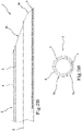
Figure 1 is a perspective view of the end of the tubular element according to the invention designed to be inserted in the body of a patient; -
Figures 2A-B are axial cross-sections of the end ofFigure 1 , according to two respective embodiments; -
Figures 3A-B show a radial cross-section of the tubular element according to the embodiments, respectively, ofFigures 2A-B . - In the accompanying drawings, the
numeral 1 denotes in general a tubular element for medical use according to the invention, hereinafter referred to aselement 1. - Hereinafter, by way of a non-limiting example, the term tubular element for medical use will be used to refer, for example, to probes, catheters and cannulas which can be used during medical operations.
- In particular, the
element 1 comprises amain body 2, a pointed end 3 and amarker 4. - The
main body 2 has a main axis of extension "X" and defines a gripping portion, preferably at a proximal end of theelement 1, by which a user can handle theelement 1, in particular for inserting it into or extracting it from the body of a patient. - The pointed end 3 is in a distal position and is configured to allow and promote insertion and movement of the
subcutaneous element 1, preferably inside a cardiovascular conduit. - For this reason, for the purpose of the invention, the distal and proximal terms are used with reference to a configuration of use of the element wherein the pointed end 3 is the end designed to be inserted into the body of the patient, whilst the proximal end is the end designed to remain outside the body of the patient and preferably allow the retaining and the manipulating of the
element 1 by the user. - The
element 1 also comprises amarker 4, that is to say, a substance different from the materials which make the rest of theelement 1 and which can be detected by suitable detection systems. - In particular, the marker may comprise a radio-opaque agent.
- If necessary, the marker may further or alternatively comprise at least one between: colouring agent, opaque agent, magnetising agent, fluorescent agent, luminescent agent etc.
- The
marker 4 is applied at least at an angular portion of the side wall of thetubular element 1 which extends from the pointed end 3 to at least a portion of themain body 2. - According to a preferred embodiment, the
marker 4 is in the form of a continuous strip of radio-opaque material which occupies only an angular portion of the side wall of theelement 1 which extends from the pointed end 3 to at least a portion of themain body 2. - In general, the
marker 4 is applied in such a way as to extend at least partly along themain body 2 as well as on the part of theelement 1 which defines the pointed end 3. - Preferably, the
marker 4 is applied at a corner portion of the side wall of theelement 1 which extends on the entiremain body 2. - In other words, the
entire element 1, therefore the entiremain body 2 and the pointed end 3, has themarker 4 applied along its entire length, in such a way as to make its entire profile detectable, irrespective of the length for which it is inserted inside the body of the patient. - Preferably, the
marker 4 is at least partly incorporated in the side wall, that is to say, themarker 4 is applied inside the side wall of theelement 1. According to a possible embodiment, not illustrated in the accompanying drawings, theelement 1 comprises afirst marker 4 applied at the pointed end 3 and asecond marker 4 at the applied at themain body 2. - These
markers 5 may have different detecting characteristics, that is to say, they are susceptible to generate different measuring signals which allow them to be distinguished in a clear manner. - In this way it is possible to detect different specific signals for the various portions which make up the
element 1, thus obtaining precise information which makes it possible to define in a clear and immediate manner the actual position of theelement 1 inside the body of the patient, in particular of the pointed end 3 and of themain body 2 separately. - Advantageously, the invention achieves the preset aims overcoming the drawbacks of the prior art by providing the user with a
tubular element 1 for medical use wherein the presence of the marker applied not only on the tip of theelement 1, but at least partly also on itsmain body 2 makes it possible to obtain, during use of theelement 1, an overall and immediate view of the arrangement of the various elements introduced inside the patient's body. In particular, the high radio-opaqueness of the marker makes the tip clearly visibility in fluoroscopy, which must be manoeuvred very carefully, despite its reduced surface area compared with that of the main body. - According to a particular embodiment, the pointed end 3 comprises a
distal end 3a and anintermediate portion 3b. - The
distal end 3a has a front edge inclined relative to the main axis of extension "X", in such a way as to form with it a first operating angle α. - In other words, the operating angle defines the angular amplitude adopted by the
element 1 at thedistal end 3a. - In particular, the first operating angle α is between 40° and 50°, preferably 45°.
- Consequently, the
distal end 3a has a pointed shape, that is to say, it defines a tip with which it is possible to effectively engage the calcified tissue concretions which immobilise the devices to be explanted. - This function is particularly important if the
element 1 is used to extract electro-catheters/catheters implanted in a heart cavity. In fact, the tip allows detachment of the sheath (constituting the outer covering of the electro-catheters) and/or the metallic parts (electrodes) from the tissues in which they are inserted and in which they could have been positioned following adherence and/or calcification processes, operating in fact like a chisel. - Preferably, the
distal end 3a has an axial length of between 0.5 mm and 5 mm. - The
intermediate portion 3b performs, on the other hand, a function of connecting between thedistal end 3a and themain body 2. - Moreover, the
intermediate portion 3b also has a front edge inclined relative to the main axis of extension "X", in such a way as to form a second operating angle β, which is different to the first operating angle α. In particular, the second operating angle β is between 10° and 30°, preferably 20°. - Preferably, the
intermediate portion 3b has an axial length of between 1.5 mm and 25 mm. - In other words, the part of the element designed to promote the insertion into the body of a patient has two different angles α, β.
- According to this embodiment, it is also possible to apply
markers 4 of different types on thedistal end 3a and on theintermediate portion 3b, in such a way that they can be detected separately. - Advantageously, synergic effect provided by the simultaneous presence of two different operating angles α, β makes it possible to better use the advantages provided by both without the relative drawbacks.
- In particular, the first operating angle α, which is preferably greater in size, provides the distal end 3 with sufficient strength to allow the
element 1 to operate correctly without being damaged, whilst the second operating angle β, which is preferably smaller in size, guarantees ease of insertion, improving manoeuvrability. - The
element 1 also comprises an innertubular layer 5 and an outertubular layer 6. - The inner
tubular layer 5 defines an inner lateral surface of theelement 1. The outertubular layer 6 is fitted around the innertubular layer 5 and defines an outer side surface of theelement 1. - In other words, the
element 1 has a segmented side wall, that is, made by radially superposing severaltubular layers - According to a preferred embodiment, the inner
tubular layer 5 and the outertubular layer 6 are made using different materials. - In particular, the materials which can be used can be biocompatible plastic materials suitably selected in particular according to their elastic properties (flexibility and twisting).
- By way of a non-limiting example, the
tubular layers - It is therefore possible to make the
element 1 using materials which have different elastic characteristics, flexibility/twisting in particular, in such a way as to modulate in a precise and accurate manner the mechanical properties in particular, as a function of the particular operating context in which theelement 1 must be used. - Moreover, the inner
tubular layer 5 has a different thickness to a radial thickness of the outertubular layer 6. - In this way, the difference in thickness also allows the overall rigidity of the
element 1 to be modulated. - In particular, the inner
tubular layer 5 has a radial thickness of between 0.10 mm and 0.25 mm, whilst the outertubular layer 6 has a radial thickness of between 0.10 mm and 0.25 mm. It should be noted, therefore, that the element may havetubular layers - In particular, the inner
tubular layer 5 and/or the outertubular layer 6 have a radial thickness which may vary and be suitably modulated along the main axis of extension "X" of thetubular element 1. - In other words, it is possible that the
element 1 has axial portions wherein the innertubular layer 5 and the outertubular layer 6 have radial thicknesses which vary, giving the element overall mechanical properties which vary as a function of the radial thicknesses. - Similarly, the material with which the inner
tubular layer 5 and/or the outertubular layer 6 are made may also be modified along at least some portions of the total length of theelement 1. - The
element 1 may also comprise at least one intermediate tubular layer, not illustrated in the accompanying drawings, interposed between the innertubular layer 5 and the outertubular layer 6. - In other words, it is possible to further improve the mechanical properties of the
element 1 introducing further tubular layers, the radial thickness and material of which can be suitably selected so as to modify the overall rigidity of theelement 1. - It is also possible to make different portions of the
element 1 using different combinations of materials and/or thicknesses for the varioustubular layers - In this context, the
marker 4 is preferably interposed between the innertubular layer 5 and the outertubular layer 6. - In this way, the
marker 4 is completely enclosed between the innertubular layer 5 and the outertubular layer 6, being incorporated inside the side wall of the element. - This aspect advantageously facilitates the process for making the element, since it is possible to make both the two
tubular layers marker 4 simultaneously and prepare the innertubular layer 5, apply themarker 4 and then make the outertubular layer 6 to cover both. - Advantageously, the presence of several concentric tubular layers made of different materials and/or thicknesses allows the mechanical properties of the element to be modified in a precise and accurate manner, thus allowing
elements 1 to be made specially designed to operate in specific situations. - For example, one of these concentric layers (typically the outermost one and/or the innermost one) may be identified in a suitable coating (hydrophilic, fluoropolymeric, etc.) with biomedical grade materials designed to minimise the possible friction which the
element 1 may encounter inside the blood vessel, that is, of another similar cannula. - The invention also relates to a percutaneous extrusion cannula configured for the complete or partial extraction of medical devices, both subcutaneous (for example of the neurological type) and from a cardiac chamber.
- In particular, the cannula comprises a tubular element as described, that is to say, which incorporates one or more of the technical features indicated above.
Claims (6)
- A tubular element (1) for the insertion of a probe, a catheter or a cannula inside a cardiovascular conduit, comprising a pointed end (3) consisting of:- a distal end (3a) having a front edge inclined relative to the main axis of extension (X) in such a way as to form a first operating angle (α);- an intermediate portion (3b) configured to join the distal end (3a) to the main body (2) and having a front edge inclined with respect to the main axis of extension (X) in such a way as to form a second operating angle (β) which is different from said first operating angle (α);characterized in thatthe first operating angle (α) is between 40° and 50°, andthe second operating angle (β) is between 10° and 30°,
- The element (1) according to claim 1 wherein said first operating angle (α) is equal to 45° and said second angle (β) is equal to 20°.
- The element (1) according to claim 1 or 2, wherein said distal end (3a) has an axial length of between 0.5 mm and 5 mm and wherein the intermediate portion (3b) has an axial length of between 2.5 mm and 25 mm.
- The element (1) according to one or more of claims 1-3, wherein said pointed end (3) is arranged to be the extreme limit, on the one hand, of a marker (4) applied at least at an angular portion of the side wall of the tubular element (1);
said marker (4) extending from said pointed end (3) to at least a portion of the main body (2) of the tubolar element (1). - The element according to claim 1, wherein the marker (4) is applied at an angular portion of the side wall of the tubular element of the entire main body (2).
- A percutaneous extraction cannula configured for the total or partial extraction of medical devices implanted below the skin or in organic cavities, for example in heart chambers, comprising a tubular element (1) according to any one of the preceding claims 1-5.
Priority Applications (1)
| Application Number | Priority Date | Filing Date | Title |
|---|---|---|---|
| EP21211009.2A EP4043059B1 (en) | 2020-11-11 | 2020-11-11 | Tubular element for medical use |
Applications Claiming Priority (2)
| Application Number | Priority Date | Filing Date | Title |
|---|---|---|---|
| EP21211009.2A EP4043059B1 (en) | 2020-11-11 | 2020-11-11 | Tubular element for medical use |
| EP20206866.4A EP4000676A1 (en) | 2020-11-11 | 2020-11-11 | Tubular element for medical use |
Related Parent Applications (2)
| Application Number | Title | Priority Date | Filing Date |
|---|---|---|---|
| EP20206866.4A Division-Into EP4000676A1 (en) | 2020-11-11 | 2020-11-11 | Tubular element for medical use |
| EP20206866.4A Division EP4000676A1 (en) | 2020-11-11 | 2020-11-11 | Tubular element for medical use |
Publications (3)
| Publication Number | Publication Date |
|---|---|
| EP4043059A1 true EP4043059A1 (en) | 2022-08-17 |
| EP4043059C0 EP4043059C0 (en) | 2025-03-05 |
| EP4043059B1 EP4043059B1 (en) | 2025-03-05 |
Family
ID=74175552
Family Applications (3)
| Application Number | Title | Priority Date | Filing Date |
|---|---|---|---|
| EP20206866.4A Pending EP4000676A1 (en) | 2020-11-11 | 2020-11-11 | Tubular element for medical use |
| EP21211009.2A Active EP4043059B1 (en) | 2020-11-11 | 2020-11-11 | Tubular element for medical use |
| EP21211085.2A Pending EP4043060A1 (en) | 2020-11-11 | 2020-11-11 | Tubular element for medical use |
Family Applications Before (1)
| Application Number | Title | Priority Date | Filing Date |
|---|---|---|---|
| EP20206866.4A Pending EP4000676A1 (en) | 2020-11-11 | 2020-11-11 | Tubular element for medical use |
Family Applications After (1)
| Application Number | Title | Priority Date | Filing Date |
|---|---|---|---|
| EP21211085.2A Pending EP4043060A1 (en) | 2020-11-11 | 2020-11-11 | Tubular element for medical use |
Country Status (1)
| Country | Link |
|---|---|
| EP (3) | EP4000676A1 (en) |
Citations (4)
| Publication number | Priority date | Publication date | Assignee | Title |
|---|---|---|---|---|
| WO2001070324A1 (en) * | 2000-03-21 | 2001-09-27 | Cook Incorporated | Introducer sheath |
| US6796976B1 (en) * | 1998-03-06 | 2004-09-28 | Scimed Life Systems, Inc. | Establishing access to the body |
| WO2017053288A1 (en) | 2015-09-24 | 2017-03-30 | Becton, Dickinson And Company | Five-bevel cannula for blood acquisition devices |
| US20170312453A1 (en) * | 2015-01-20 | 2017-11-02 | Terumo Kabushiki Kaisha | Injection needle assembly and injector provided therewith for injecting drug solution into upper layer of skin |
Family Cites Families (7)
| Publication number | Priority date | Publication date | Assignee | Title |
|---|---|---|---|---|
| US4588399A (en) * | 1980-05-14 | 1986-05-13 | Shiley Incorporated | Cannula with radiopaque tip |
| US5203777A (en) * | 1992-03-19 | 1993-04-20 | Lee Peter Y | Radiopaque marker system for a tubular device |
| US8535293B2 (en) * | 2004-04-13 | 2013-09-17 | Gyrus Acmi, Inc. | Atraumatic ureteral access sheath |
| WO2015126926A1 (en) * | 2014-02-18 | 2015-08-27 | Massachusetts Institute Of Technology | Tissue collection needle |
| EP3263167B1 (en) * | 2016-06-30 | 2023-06-28 | Wellspect AB | Urinary catheter with varying properties |
| JP2021522885A (en) * | 2018-05-01 | 2021-09-02 | インセプト・リミテッド・ライアビリティ・カンパニーIncept,Llc | Devices and methods for removing obstructive substances from intravascular sites |
| DE102018122616A1 (en) * | 2018-09-17 | 2020-03-19 | Universität des Saarlandes | Modular cannula device |
-
2020
- 2020-11-11 EP EP20206866.4A patent/EP4000676A1/en active Pending
- 2020-11-11 EP EP21211009.2A patent/EP4043059B1/en active Active
- 2020-11-11 EP EP21211085.2A patent/EP4043060A1/en active Pending
Patent Citations (4)
| Publication number | Priority date | Publication date | Assignee | Title |
|---|---|---|---|---|
| US6796976B1 (en) * | 1998-03-06 | 2004-09-28 | Scimed Life Systems, Inc. | Establishing access to the body |
| WO2001070324A1 (en) * | 2000-03-21 | 2001-09-27 | Cook Incorporated | Introducer sheath |
| US20170312453A1 (en) * | 2015-01-20 | 2017-11-02 | Terumo Kabushiki Kaisha | Injection needle assembly and injector provided therewith for injecting drug solution into upper layer of skin |
| WO2017053288A1 (en) | 2015-09-24 | 2017-03-30 | Becton, Dickinson And Company | Five-bevel cannula for blood acquisition devices |
Also Published As
| Publication number | Publication date |
|---|---|
| EP4043059C0 (en) | 2025-03-05 |
| EP4043060A1 (en) | 2022-08-17 |
| EP4000676A1 (en) | 2022-05-25 |
| EP4043059B1 (en) | 2025-03-05 |
Similar Documents
| Publication | Publication Date | Title |
|---|---|---|
| US20070005019A1 (en) | Catheter assembly | |
| EP2512576B1 (en) | Intravascular catheter with positioning markers | |
| CA2223990C (en) | Guiding catheter for coronary sinus | |
| EP2473224B1 (en) | Coaxial transseptal guide-wire and needle assembly | |
| EP2002857B1 (en) | Retention sleeve having cuff for insertion into subcutaneous region | |
| JP2012513286A (en) | Ultrasound visualization endoscope access device | |
| CN112789079B (en) | Guide wire supporting catheter | |
| CN111655321A (en) | puncture system | |
| US20220379079A1 (en) | Catheter tube for a steerable catheter, and method for implanting an implantable medical device by means of a steerable catheter | |
| US20230201543A1 (en) | Method and system for abscess drainage | |
| US20220142668A1 (en) | Tubular element for medical use | |
| EP4043059B1 (en) | Tubular element for medical use | |
| EP3760144B1 (en) | Tubular element for medical use | |
| CN116194171A (en) | Catheter and method for engaging catheter | |
| WO2020194907A1 (en) | Catheter and treatment method | |
| IT201900010884A1 (en) | Tubular element for medical use | |
| CN219804126U (en) | Balloon catheter | |
| JP2026043056A (en) | Catheters and catheter systems | |
| CN213252366U (en) | Anterior-opening visualization PICC catheter | |
| US20230398284A1 (en) | Devices, systems, and methods for delivering fluid through a tubular element | |
| US20180098756A1 (en) | Biopsy system and method of use | |
| IT201900010887A1 (en) | Tubular element for medical use | |
| WO2018074074A1 (en) | Catheter assembly | |
| WO2024080003A1 (en) | Catheter and catheter system | |
| US20190255287A1 (en) | Adjustable catheter straightener |
Legal Events
| Date | Code | Title | Description |
|---|---|---|---|
| PUAI | Public reference made under article 153(3) epc to a published international application that has entered the european phase |
Free format text: ORIGINAL CODE: 0009012 |
|
| STAA | Information on the status of an ep patent application or granted ep patent |
Free format text: STATUS: THE APPLICATION HAS BEEN PUBLISHED |
|
| AC | Divisional application: reference to earlier application |
Ref document number: 4000676 Country of ref document: EP Kind code of ref document: P |
|
| AK | Designated contracting states |
Kind code of ref document: A1 Designated state(s): AL AT BE BG CH CY CZ DE DK EE ES FI FR GB GR HR HU IE IS IT LI LT LU LV MC MK MT NL NO PL PT RO RS SE SI SK SM TR |
|
| STAA | Information on the status of an ep patent application or granted ep patent |
Free format text: STATUS: REQUEST FOR EXAMINATION WAS MADE |
|
| 17P | Request for examination filed |
Effective date: 20220927 |
|
| RBV | Designated contracting states (corrected) |
Designated state(s): AL AT BE BG CH CY CZ DE DK EE ES FI FR GB GR HR HU IE IS IT LI LT LU LV MC MK MT NL NO PL PT RO RS SE SI SK SM TR |
|
| P01 | Opt-out of the competence of the unified patent court (upc) registered |
Effective date: 20231123 |
|
| GRAP | Despatch of communication of intention to grant a patent |
Free format text: ORIGINAL CODE: EPIDOSNIGR1 |
|
| STAA | Information on the status of an ep patent application or granted ep patent |
Free format text: STATUS: GRANT OF PATENT IS INTENDED |
|
| INTG | Intention to grant announced |
Effective date: 20241014 |
|
| GRAS | Grant fee paid |
Free format text: ORIGINAL CODE: EPIDOSNIGR3 |
|
| GRAA | (expected) grant |
Free format text: ORIGINAL CODE: 0009210 |
|
| STAA | Information on the status of an ep patent application or granted ep patent |
Free format text: STATUS: THE PATENT HAS BEEN GRANTED |
|
| AC | Divisional application: reference to earlier application |
Ref document number: 4000676 Country of ref document: EP Kind code of ref document: P |
|
| AK | Designated contracting states |
Kind code of ref document: B1 Designated state(s): AL AT BE BG CH CY CZ DE DK EE ES FI FR GB GR HR HU IE IS IT LI LT LU LV MC MK MT NL NO PL PT RO RS SE SI SK SM TR |
|
| REG | Reference to a national code |
Ref country code: GB Ref legal event code: FG4D |
|
| REG | Reference to a national code |
Ref country code: CH Ref legal event code: EP |
|
| REG | Reference to a national code |
Ref country code: IE Ref legal event code: FG4D |
|
| REG | Reference to a national code |
Ref country code: DE Ref legal event code: R096 Ref document number: 602020047470 Country of ref document: DE |
|
| P04 | Withdrawal of opt-out of the competence of the unified patent court (upc) registered |
Free format text: CASE NUMBER: APP_13438/2025 Effective date: 20250318 |
|
| U01 | Request for unitary effect filed |
Effective date: 20250313 |
|
| U07 | Unitary effect registered |
Designated state(s): AT BE BG DE DK EE FI FR IT LT LU LV MT NL PT RO SE SI Effective date: 20250321 |
|
| PG25 | Lapsed in a contracting state [announced via postgrant information from national office to epo] |
Ref country code: RS Free format text: LAPSE BECAUSE OF FAILURE TO SUBMIT A TRANSLATION OF THE DESCRIPTION OR TO PAY THE FEE WITHIN THE PRESCRIBED TIME-LIMIT Effective date: 20250605 |
|
| PG25 | Lapsed in a contracting state [announced via postgrant information from national office to epo] |
Ref country code: ES Free format text: LAPSE BECAUSE OF FAILURE TO SUBMIT A TRANSLATION OF THE DESCRIPTION OR TO PAY THE FEE WITHIN THE PRESCRIBED TIME-LIMIT Effective date: 20250305 |
|
| PG25 | Lapsed in a contracting state [announced via postgrant information from national office to epo] |
Ref country code: NO Free format text: LAPSE BECAUSE OF FAILURE TO SUBMIT A TRANSLATION OF THE DESCRIPTION OR TO PAY THE FEE WITHIN THE PRESCRIBED TIME-LIMIT Effective date: 20250605 |
|
| PG25 | Lapsed in a contracting state [announced via postgrant information from national office to epo] |
Ref country code: HR Free format text: LAPSE BECAUSE OF FAILURE TO SUBMIT A TRANSLATION OF THE DESCRIPTION OR TO PAY THE FEE WITHIN THE PRESCRIBED TIME-LIMIT Effective date: 20250305 |
|
| PG25 | Lapsed in a contracting state [announced via postgrant information from national office to epo] |
Ref country code: GR Free format text: LAPSE BECAUSE OF FAILURE TO SUBMIT A TRANSLATION OF THE DESCRIPTION OR TO PAY THE FEE WITHIN THE PRESCRIBED TIME-LIMIT Effective date: 20250606 |
|
| PG25 | Lapsed in a contracting state [announced via postgrant information from national office to epo] |
Ref country code: SM Free format text: LAPSE BECAUSE OF FAILURE TO SUBMIT A TRANSLATION OF THE DESCRIPTION OR TO PAY THE FEE WITHIN THE PRESCRIBED TIME-LIMIT Effective date: 20250305 |
|
| PG25 | Lapsed in a contracting state [announced via postgrant information from national office to epo] |
Ref country code: PL Free format text: LAPSE BECAUSE OF FAILURE TO SUBMIT A TRANSLATION OF THE DESCRIPTION OR TO PAY THE FEE WITHIN THE PRESCRIBED TIME-LIMIT Effective date: 20250305 |
|
| PG25 | Lapsed in a contracting state [announced via postgrant information from national office to epo] |
Ref country code: CZ Free format text: LAPSE BECAUSE OF FAILURE TO SUBMIT A TRANSLATION OF THE DESCRIPTION OR TO PAY THE FEE WITHIN THE PRESCRIBED TIME-LIMIT Effective date: 20250305 |
|
| PG25 | Lapsed in a contracting state [announced via postgrant information from national office to epo] |
Ref country code: SK Free format text: LAPSE BECAUSE OF FAILURE TO SUBMIT A TRANSLATION OF THE DESCRIPTION OR TO PAY THE FEE WITHIN THE PRESCRIBED TIME-LIMIT Effective date: 20250305 |
|
| PG25 | Lapsed in a contracting state [announced via postgrant information from national office to epo] |
Ref country code: IS Free format text: LAPSE BECAUSE OF FAILURE TO SUBMIT A TRANSLATION OF THE DESCRIPTION OR TO PAY THE FEE WITHIN THE PRESCRIBED TIME-LIMIT Effective date: 20250705 |
|
| U20 | Renewal fee for the european patent with unitary effect paid |
Year of fee payment: 6 Effective date: 20251127 |
|
| PLBE | No opposition filed within time limit |
Free format text: ORIGINAL CODE: 0009261 |
|
| STAA | Information on the status of an ep patent application or granted ep patent |
Free format text: STATUS: NO OPPOSITION FILED WITHIN TIME LIMIT |
|
| REG | Reference to a national code |
Ref country code: CH Ref legal event code: L10 Free format text: ST27 STATUS EVENT CODE: U-0-0-L10-L00 (AS PROVIDED BY THE NATIONAL OFFICE) Effective date: 20260114 |
|
| 26N | No opposition filed |
Effective date: 20251208 |