US20180098756A1 - Biopsy system and method of use - Google Patents
Biopsy system and method of use Download PDFInfo
- Publication number
- US20180098756A1 US20180098756A1 US15/291,699 US201615291699A US2018098756A1 US 20180098756 A1 US20180098756 A1 US 20180098756A1 US 201615291699 A US201615291699 A US 201615291699A US 2018098756 A1 US2018098756 A1 US 2018098756A1
- Authority
- US
- United States
- Prior art keywords
- needle
- elongated shaft
- shaft
- distal
- biopsy system
- Prior art date
- Legal status (The legal status is an assumption and is not a legal conclusion. Google has not performed a legal analysis and makes no representation as to the accuracy of the status listed.)
- Abandoned
Links
- 238000000034 method Methods 0.000 title claims description 14
- 238000001574 biopsy Methods 0.000 title description 34
- 238000013188 needle biopsy Methods 0.000 claims abstract description 19
- 210000004072 lung Anatomy 0.000 claims description 34
- 238000009954 braiding Methods 0.000 claims description 15
- 239000012530 fluid Substances 0.000 claims description 6
- 239000000463 material Substances 0.000 description 6
- 208000007123 Pulmonary Atelectasis Diseases 0.000 description 3
- 230000000740 bleeding effect Effects 0.000 description 3
- POIUWJQBRNEFGX-XAMSXPGMSA-N cathelicidin Chemical compound C([C@@H](C(=O)N[C@@H](CCCNC(N)=N)C(=O)N[C@@H](CCCCN)C(=O)N[C@@H](CO)C(=O)N[C@@H](CCCCN)C(=O)N[C@@H](CCC(O)=O)C(=O)N[C@@H](CCCCN)C(=O)N[C@@H]([C@@H](C)CC)C(=O)NCC(=O)N[C@@H](CCCCN)C(=O)N[C@@H](CCC(O)=O)C(=O)N[C@@H](CC=1C=CC=CC=1)C(=O)N[C@@H](CCCCN)C(=O)N[C@@H](CCCNC(N)=N)C(=O)N[C@@H]([C@@H](C)CC)C(=O)N[C@@H](C(C)C)C(=O)N[C@@H](CCC(N)=O)C(=O)N[C@@H](CCCNC(N)=N)C(=O)N[C@@H]([C@@H](C)CC)C(=O)N[C@@H](CCCCN)C(=O)N[C@@H](CC(O)=O)C(=O)N[C@@H](CC=1C=CC=CC=1)C(=O)N[C@@H](CC(C)C)C(=O)N[C@@H](CCCNC(N)=N)C(=O)N[C@@H](CC(N)=O)C(=O)N[C@@H](CC(C)C)C(=O)N[C@@H](C(C)C)C(=O)N1[C@@H](CCC1)C(=O)N[C@@H](CCCNC(N)=N)C(=O)N[C@@H]([C@@H](C)O)C(=O)N[C@@H](CCC(O)=O)C(=O)N[C@@H](CO)C(O)=O)NC(=O)[C@H](CC=1C=CC=CC=1)NC(=O)[C@H](CC(O)=O)NC(=O)CNC(=O)[C@H](CC(C)C)NC(=O)[C@@H](N)CC(C)C)C1=CC=CC=C1 POIUWJQBRNEFGX-XAMSXPGMSA-N 0.000 description 3
- 239000004033 plastic Substances 0.000 description 3
- 229920003023 plastic Polymers 0.000 description 3
- 239000000853 adhesive Substances 0.000 description 2
- 230000001070 adhesive effect Effects 0.000 description 2
- 230000006835 compression Effects 0.000 description 2
- 238000007906 compression Methods 0.000 description 2
- -1 for example Substances 0.000 description 2
- 239000002184 metal Substances 0.000 description 2
- 238000012986 modification Methods 0.000 description 2
- 230000004048 modification Effects 0.000 description 2
- 229910001220 stainless steel Inorganic materials 0.000 description 2
- 239000010935 stainless steel Substances 0.000 description 2
- 229920001169 thermoplastic Polymers 0.000 description 2
- 239000004677 Nylon Substances 0.000 description 1
- 229920002614 Polyether block amide Polymers 0.000 description 1
- 239000004954 Polyphthalamide Substances 0.000 description 1
- 230000000712 assembly Effects 0.000 description 1
- 238000000429 assembly Methods 0.000 description 1
- 238000005452 bending Methods 0.000 description 1
- 238000004891 communication Methods 0.000 description 1
- 238000013170 computed tomography imaging Methods 0.000 description 1
- 230000008878 coupling Effects 0.000 description 1
- 238000010168 coupling process Methods 0.000 description 1
- 238000005859 coupling reaction Methods 0.000 description 1
- 238000002594 fluoroscopy Methods 0.000 description 1
- 229920001903 high density polyethylene Polymers 0.000 description 1
- 238000010562 histological examination Methods 0.000 description 1
- 238000003384 imaging method Methods 0.000 description 1
- 238000003780 insertion Methods 0.000 description 1
- 230000037431 insertion Effects 0.000 description 1
- 238000002595 magnetic resonance imaging Methods 0.000 description 1
- 229920001778 nylon Polymers 0.000 description 1
- 229920006255 plastic film Polymers 0.000 description 1
- 229920000139 polyethylene terephthalate Polymers 0.000 description 1
- 239000005020 polyethylene terephthalate Substances 0.000 description 1
- 229920006375 polyphtalamide Polymers 0.000 description 1
- 239000004810 polytetrafluoroethylene Substances 0.000 description 1
- 229920001343 polytetrafluoroethylene Polymers 0.000 description 1
- 229920002635 polyurethane Polymers 0.000 description 1
- 239000004814 polyurethane Substances 0.000 description 1
- 238000002601 radiography Methods 0.000 description 1
- 229920002379 silicone rubber Polymers 0.000 description 1
- 239000004945 silicone rubber Substances 0.000 description 1
- 230000007704 transition Effects 0.000 description 1
- 238000002604 ultrasonography Methods 0.000 description 1
Images

Classifications
-
- A—HUMAN NECESSITIES
- A61—MEDICAL OR VETERINARY SCIENCE; HYGIENE
- A61B—DIAGNOSIS; SURGERY; IDENTIFICATION
- A61B10/00—Instruments for taking body samples for diagnostic purposes; Other methods or instruments for diagnosis, e.g. for vaccination diagnosis, sex determination or ovulation-period determination; Throat striking implements
- A61B10/02—Instruments for taking cell samples or for biopsy
- A61B10/0233—Pointed or sharp biopsy instruments
- A61B10/0266—Pointed or sharp biopsy instruments means for severing sample
Definitions
- the present disclosure relates to a surgical system for taking tissue samples and, more specifically, to surgical systems for performing needle aspiration biopsies of tissue.
- Needle biopsy is a medical procedure used to obtain a tissue sample from an area of the body.
- the tissue sample is usually tested to assist in diagnosing a medical condition or to assess the effectiveness of a particular treatment.
- Percutaneous needle lung biopsy or transthoracic needle lung biopsy involves the use of a needle to enter the lung through the skin to obtain a biopsy sample.
- great care is taken to avoid inadvertent puncturing of the lung, which may lead to bleeding and/or lung collapse due to leakage from the lung.
- bleeding and lung collapse are more likely with larger, relatively stiff needles and/or flat-tipped needles.
- using a needle having a relatively small diameter may be undesirable because the sample obtained using such a small needle may be insufficient for histological examination.
- biopsy needles are only one component of a biopsy system.
- a biopsy system used for percutaneous lung biopsies may include a biopsy needle having a flexible shaft and a flexible access catheter through which the biopsy needle gains entry into a target tissue site in the lung.
- Such a biopsy system is easily navigable through the various narrow passageways of the lung due to the flexibility of the access catheter and the flexibility of the biopsy needle, which facilitates conformance of these components to the deviating passageways of the lung.
- the components of a system used for percutaneous lung biopsy should be designed to minimize the chance of lung collapse, have sufficient flexibility for navigation through the deviating passageways of the lung, improve the sample size of a biopsy, and also maximize the ability to pierce the skin and other tissue while minimizing the chance of bleeding.
- This disclosure relates generally to a needle biopsy system that includes an elongated shaft and a needle shaft.
- the elongated shaft includes a proximal portion, an intermediate portion more flexible than the proximal portion, and a distal portion that is less flexible than the intermediate portion.
- the needle shaft has a distal tip configured to cut and receive a sample of tissue and is longitudinally movable through the elongated shaft between a first position and a second position. In the first position, the distal tip of the needle shaft is disposed within the elongated shaft, and in the second position, the distal tip of the needle shaft extends distally from the distal portion of the elongated shaft to cut and receive a sample of tissue.
- the elongated shaft may have an outer tubular surface, an inner tubular surface, and a braiding extending longitudinally between the outer tubular surface and the inner tubular surface.
- the braiding may extend along the proximal and distal portions of the elongated shaft and terminate proximally of the distal portion of the elongated shaft.
- the braiding may include a plurality of interwoven metallic braid filaments.
- the inner tubular surface may have a constant durometer along its length.
- the outer tubular surface may have a higher durometer along the proximal portion of the elongated shaft than at the intermediate portion and the distal portion of the elongated shaft.
- the proximal portion of the elongated shaft may be less flexible than the intermediate portion and the distal portion of the elongated shaft.
- distal portion of the elongated shaft may be tapered in a distal direction.
- the biopsy system may further include a first hub coupled to the proximal portion of the elongated shaft and a second hub coupled to a proximal portion of the needle shaft.
- the first hub may be configured to receive the needle shaft therethrough.
- the needle shaft may be configured to move through and relative to the first hub in response to movement of the second hub.
- the first hub may have a proximal portion configured to detachably engage a distal portion of the second hub, and the second hub may be configured for a fluid tight connection with a syringe.
- the biopsy system may further include a stylet configured to move longitudinally within a lumen defined through the needle shaft.
- the stylet may include a blunt distal tip configured to be disposed within the distal tip of the needle shaft.
- the stylet may be less flexible than the intermediate portion of the elongated shaft.
- the method includes flexing a portion of an elongated shaft to facilitate moving the elongated shaft through an airway of a lung and positioning a blunt distal portion of the elongated shaft adjacent tissue in the lung.
- An intermediate portion of the elongated shaft is more flexible than a proximal portion of the elongated shaft, and the blunt distal portion is less flexible than the intermediate portion and more flexible than the proximal portion.
- the method further includes moving a needle shaft longitudinally within the elongated shaft to extend a distal tip of the needle shaft from the distal portion of the elongated shaft to cut and receiving a sample of tissue.
- the method may further include moving a blunt distal tip of a stylet in a proximal direction to a position proximal of the distal tip of the needle shaft.
- the method may include moving a stylet longitudinally within a lumen defined through the needle shaft to position a distal tip of the stylet within the distal portion of the needle shaft.
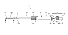
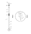
- FIG. 1 is a schematic illustration of a biopsy system including a catheter assembly and a needle assembly used for percutaneous removal of a sample of tissue;
- FIG. 2 is a cross-sectional view, taken along line 2 - 2 of FIG. 1 , illustrating a needle shaft disposed within an elongated shaft of the catheter assembly;
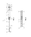
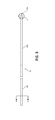
- FIG. 3 is a side view of the elongated shaft of FIG. 1 ;
- FIG. 4 is an enlarged view of detail 4 of FIG. 3 illustrating a distal portion of the elongated shaft
- FIG. 5 is a cross-sectional view, taken along line 5 - 5 of FIG. 4 , of the distal portion of the elongated shaft;
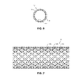
- FIG. 6 is a cross-sectional view, taken along line 6 - 6 of FIG. 3 , illustrating a plurality of layers of the elongated shaft;
- FIG. 7 is a side view of braiding of the elongated shaft of FIG. 6 ;
- FIG. 8 is a schematic illustration of the biopsy system of FIG. 1 illustrating a distal tip of the needle shaft extending distally from the elongated shaft;
- FIG. 9 is an enlarged view of detail 9 of FIG. 8 ;
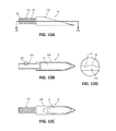
- FIG. 10A is an enlarged side view of the distal tip of the needle shaft of FIG. 9 ;
- FIG. 10B is a cross-sectional view, taken alone line 10 B- 10 B of FIG. 10A , of the distal tip of the needle shaft of FIG. 9 ;
- FIG. 10C is an enlarged top view of the distal tip of the needle shaft of FIG. 9 ;
- FIG. 10D is an enlarged view of detail 10 D of FIG. 10B illustrating threading of a proximal portion of the distal tip of the needle shaft of FIG. 9 ;
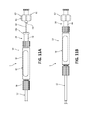
- FIG. 11A is a partial side view of the biopsy system of FIG. 1 including a stylet disposed in a first position;
- FIG. 11B is a side view of the biopsy system of FIG. 11A illustrating the stylet disposed in a second position
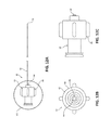
- FIG. 12A is a side view of the stylet of FIG. 11A ;
- FIG. 12B is a front view of the stylet of FIG. 11A ;
- FIG. 12C is an enlarged view of detail 12 C of FIG. 12A illustrating a hub of the stylet.
- proximal refers to that portion of the described biopsy system including the catheter assembly, the needle assembly, or the stylet, that is closer to the user
- distal refers to that portion of the biopsy system including the catheter assembly, the needle assembly, or the stylet, that is farther from the user.
- the present disclosure provides a biopsy system for percutaneous removal of a sample of tissue, for example, tissue in the lung.
- the biopsy system generally includes a catheter assembly and a needle assembly.
- the needle assembly includes a needle shaft movably disposed within an elongated shaft of the catheter assembly.
- a stylet is movably disposed within the needle shaft.
- the needle shaft has a proximal portion, a distal portion, and a distal tip that is configured for cutting and receiving a sample of tissue.
- the biopsy system has sufficient flexibility to facilitate navigation through passageways of the lung. More specifically, the flexibility of any one of the proximal portion, the distal portion, or the distal tip of the needle shaft may differ or be the same relative to each other.
- the distal portion may be more flexible than the proximal portion, less flexible than the proximal portion, or have the same flexibility as the proximal portion.
- the distal tip may be less flexible than either of the distal or proximal portions, more flexible than either of the distal or proximal portions, or have the same flexibility as either of the distal or proximal portions.
- Biopsy system 1 for percutaneous removal of a tissue sample, for example, lung tissue.
- Biopsy system 1 generally includes a catheter assembly 10 , a needle assembly 30 , and in some embodiments (see FIGS. 11A-12C ) a stylet 60 .
- the catheter assembly 10 includes an elongated shaft 12 extending distally from a hub 14 .
- the elongated shaft 12 has a proximal portion 12 a , an intermediate portion 12 b , and a distal portion 12 c .
- the needle assembly 30 includes a needle shaft 40 having a distal tip 42 and extending distally from a hub 46 .
- the elongated shaft 12 of the catheter assembly 10 may be, for example, a catheter, a cannula, a tube, or the like.
- the needle shaft 40 of the needle assembly 30 is longitudinally movable through the elongated shaft 12 of the catheter assembly 10 to move the distal tip 42 of the needle shaft 40 from a first position disposed within the elongated shaft 12 , as shown in FIGS. 1 and 2 , to a second position deployed from the distal portion 12 c of the elongated shaft 12 for cutting and receiving tissue, as shown in FIGS. 8 and 9 .
- hub 14 of catheter assembly 10 includes an elongated handle portion 16 and a connector cap 18 .
- Handle portion 16 of hub 14 is configured to be grasped by a hand of a clinician during use of biopsy system 1 .
- Handle portion 16 has a distal portion 16 b and a proximal portion 16 a configured to be detachably coupled to hub 46 of needle assembly 30 .
- Connector cap 18 of hub 14 is attached to distal portion 16 b of handle portion 16 and is configured to couple handle portion 16 to proximal portion 12 a of elongated shaft 12 .
- connector cap 18 includes threading (e.g., female threading) defined therein for threading engagement to corresponding threading (e.g., male threading) defined on proximal portion 12 a of elongated shaft 12 .
- hub 14 may be coupled to proximal portion 12 a of elongated shaft 12 , either permanently or detachably, via any suitable fastening engagement, for example, compression fit, friction-fit, interference fit, snap-fit, adhesives, or the like.
- proximal portion 12 a , intermediate portion 12 b , and distal portion 12 c of elongated shaft 12 of catheter assembly 10 may differ in flexibility relative to each other.
- proximal portion 12 a of elongated shaft 12 has a first flexibility
- intermediate portion 12 b of elongated shaft 12 has a second flexibility that is greater than the first flexibility of proximal portion 12 a
- distal portion 12 c has a third flexibility that is less than the second flexibility of intermediate portion 12 b .
- the first flexibility of proximal portion 12 a may be less than each of the second and third flexibilities of distal portion and distal tip 12 b , 12 c , respectively.
- Elongated shaft 12 of catheter assembly 10 may have a total overall length of about 1300 mm to about 1500 mm and, in some embodiments, about 1400 mm.
- Intermediate portion 12 b may have an overall length of about 40 mm to about 60 mm and, in some embodiments, about 52 mm.
- Distal portion 12 c may have an overall length of about 1 mm to about 3 mm and, in some embodiments, about 2 mm.
- Distal portion 12 c tapers in a distal direction and terminates in a blunt, distal face configured for atraumatic insertion through tissue.
- distal portion 12 c provides for a smooth transition from distal portion 12 c of elongated shaft 12 to distal tip 42 of needle shaft 40 when distal tip 42 is deployed from distal portion 12 c of elongated shaft 12 , as shown in FIGS. 8 and 9 .
- distal portion 12 c may terminate in a sharpened tip configured to pierce tissue.
- elongated shaft 12 of catheter assembly 10 includes an inner tubular surface 24 and an outer tubular surface 26 .
- Inner tubular surface 24 is disposed within the outer tubular surface 26 and defines a longitudinally-extending inner lumen 22 ( FIGS. 2, 5, and 6 ) therein configured to slidably receive needle shaft 40 therethrough.
- Inner lumen 22 is in fluid communication with a longitudinal passageway 20 defined through handle portion 16 of catheter assembly 10 .
- inner tubular surface 24 may have a substantially constant durometer along its length and is in the form of a plastic liner or film fabricated from PTFE.
- inner tubular surface 24 may be fabricated from any suitable plastic (e.g., silicone rubber, polyurethane, PET, thermoplastic polymers, and/or nylon). In embodiments, inner tubular surface 24 may have a durometer of about shore A65 to about shore A75. In some embodiments, inner tubular surface 24 may have a durometer of about shore A70.
- suitable plastic e.g., silicone rubber, polyurethane, PET, thermoplastic polymers, and/or nylon.
- inner tubular surface 24 may have a durometer of about shore A65 to about shore A75. In some embodiments, inner tubular surface 24 may have a durometer of about shore A70.
- outer tubular surface 26 of elongated shaft 12 has a varying flexibility along its length to give each of proximal portion 12 a , intermediate portion 12 b , and distal portion 12 c of elongated shaft 12 a distinct hardness, which facilitates navigation of elongated shaft 12 through the airways of the lung.
- outer tubular surface 26 along proximal portion 12 a of elongated shaft 12 has a durometer of about shore A70 to about shore A80 and, in some embodiments, a durometer of about shore A74.
- the outer tubular surface 26 along proximal portion 12 a of elongated shaft 12 may be fabricated from a plastic material, such as, for example, polyphthalamide.
- proximal portion 12 a of outer tubular surface 26 may be fabricated from any suitable flexible material.
- Outer tubular surface 26 along intermediate portion 12 b of elongated shaft 12 has a durometer of about shore A35 to about shore A45 and, in some embodiments, a durometer of about shore A40.
- the portion of outer tubular surface 26 disposed along intermediate portion 12 b of elongated shaft 12 is made of a more flexible material than the portion of outer tubular surface 26 disposed along proximal portion 12 a of elongated shaft 12
- intermediate portion 12 b of elongated shaft 12 is more flexible than proximal portion 12 a of elongated shaft 12 .
- Outer tubular surface 26 along intermediate portion 12 b of elongated shaft 12 may be fabricated from a plastic material, such as, for example, polyether block amide.
- the portion of outer tubular surface 26 disposed along intermediate portion 12 b of elongated shaft 12 may be fabricated from any suitable flexible material, including the same material as the portion of outer tubular surface 26 disposed along proximal portion 12 a of elongated shaft 12 while still having a greater flexibility than the portion of the outer tubular surface 26 disposed along proximal portion 12 a of elongated shaft 12 .
- outer tubular surface 26 disposed along distal portion 12 c of elongated shaft 12 has a durometer of about shore A50 to about shore A60 and, in some embodiments, a durometer of about shore A55. As such, outer tubular surface 26 disposed along distal portion 12 c may make distal portion 12 c of elongated shaft 12 less flexible than intermediate portion 12 b of elongated shaft 12 , but more flexible than proximal portion 12 a of elongated shaft 12 .
- distal portion 12 c of elongated shaft 12 is less flexible relative to intermediate portion 12 b of elongated shaft 12 allows for distal portion 12 c of elongated shaft 12 to be maintained in position relative to target tissue by being less susceptible to bending or flexing when abutting the target tissue.
- elongated shaft 12 of catheter assembly 10 includes braiding 28 disposed between the inner and outer tubular surfaces 24 , 26 .
- Braiding extends longitudinally along proximal portion 12 a of elongated shaft 12 and intermediate portion 12 b of outer shaft, but terminates proximally of distal portion 12 c of elongated shaft 12 such that distal portion 12 c of elongated shaft 12 is devoid of braiding 28 .
- braiding 28 may extend longitudinally along proximal portion 12 a , intermediate portion 12 b , and distal portion 12 c of elongated shaft 12 .
- Braiding 28 includes a plurality of interwoven metallic braid filaments 28 a , 28 b , 28 c arranged in a mesh-like configuration. Braiding 28 increases the structural integrity of elongated shaft 12 while allowing elongated shaft 12 to remain flexible.
- Each filament 28 a - c of braiding 28 may be a flattened sheet or ribbon fabricated from a metal, for example, stainless steel.
- braiding 28 may be fabricated from non-metallic filaments, for example, thermoplastic polymers.
- needle shaft 40 of needle assembly 30 is configured to be moved within inner lumen 22 ( FIGS. 2, 5, and 6 ) of elongated shaft 12 between a first position in which distal tip 42 of needle shaft 40 is disposed within elongated shaft 12 ( FIGS. 1 and 2 ) and a second position in which distal tip 42 extends distally from distal portion 12 c of elongated shaft 12 ( FIGS. 8 and 9 ).
- Needle shaft 40 has a proximal portion 40 a and a distal portion 40 b and defines a longitudinally-extending lumen 44 therethrough.
- biopsy system 1 including the length of distal tip 42 and elongated shaft 12
- biopsy system 1 may have an overall length of about 120 cm to about 150 cm and, in some embodiments, about 130 cm.
- Hub 46 of needle assembly 30 may be fixedly or detachably coupled to proximal portion 40 a of needle shaft 40 .
- Hub 46 has a distal portion 46 b configured for detachable coupling with handle portion 16 of hub 14 .
- hub 46 of needle assembly 30 detachably couples to distal portion 16 b of handle portion 16 of catheter assembly 10 to maintain needle shaft 40 in the second position relative to elongated shaft 12 .
- Hub 46 of needle assembly 30 has a proximal portion 46 a that may be in the form of a luer lock configured to form a fluid-tight connection with a syringe (not shown) and/or vacuum (not shown) for aspiration of a tissue sample.
- Distal tip 42 of needle shaft 40 may have an overall length of between about 0.25 inches and about 0.5 inches. In some embodiments, distal tip 42 may have an overall length of about 0.325 inches. Distal tip 42 has a proximal portion 42 a coupled to distal portion 40 b of needle shaft 40 and a distal portion 42 b in the form of a sharpened tip configured to pierce tissue. Proximal portion 42 a of distal tip 42 is fixedly disposed within lumen 44 of needle shaft 40 . In the illustrated embodiment, proximal portion 42 a of distal tip 42 has an outer surface 48 with threading 50 defined therein, which assists in securing proximal portion 42 a of distal tip 42 to distal portion 40 b of needle shaft 40 .
- the threading 50 has a truncated square pyramid cross-sectional shape having a width of between about 0.08 inches and about 0.012 inches and, in some embodiments, a width of about 0.010 inches.
- threading 50 may have any suitable cross-sectional shape, such as, for example, triangular, square, rounded, or the like.
- proximal portion 42 a of distal tip 42 may be fastened to distal portion 40 b of needle shaft 40 via any suitable fastening engagement, for example, adhesives, friction-fit, compression fit, interference fit, fasteners, or the like. It is contemplated that distal tip 42 may be integrally connected to or monolithically formed with distal portion 40 b of needle shaft 40 .
- Distal portion 42 b of distal tip 42 may be fabricated from metal (e.g., stainless steel) and defines a hollow interior 52 configured for receipt of tissue. Distal portion 42 b of distal tip 42 has a lancet point configuration. It is contemplated that distal portion 42 b of distal tip 42 may be any suitable needle tip type of any suitable geometry and any suitable gauge (e.g., 18 gauge) configured to pierce tissue.
- metal e.g., stainless steel
- distal portion 42 b of distal tip 42 has a lancet point configuration. It is contemplated that distal portion 42 b of distal tip 42 may be any suitable needle tip type of any suitable geometry and any suitable gauge (e.g., 18 gauge) configured to pierce tissue.
- biopsy system 1 may include a stylet 60 configured to be slidably received within lumen 44 of needle shaft 40 .
- Stylet 60 includes a hub 62 and a shaft 64 extending distally from hub 62 .
- Hub 62 includes an outer handle portion 66 and an inner tube 68 disposed within handle portion 66 .
- Handle portion 66 of hub 62 may be a female luer connector configured to form a fluid tight seal with proximal portion 46 a of hub 46 of needle shaft 40 .
- handle portion 66 of hub 62 may be any suitable connector (e.g., a threaded connector) for forming a detachable connection with hub 46 of needle shaft 40 .
- Inner tube 68 of hub 62 extends distally from handle portion 66 of hub 62 and is configured to form a fluid-tight seal with lumen 44 ( FIG. 2 ) of needle shaft 40 such that fluid may be passed through hub 62 and into lumen 44 when stylet 60 is coupled to needle shaft 40 .
- Shaft 64 of stylet 60 is disposed radially outward of inner tube 68 of hub 62 so as to not interfere with fluid passed between inner tube 68 of stylet 60 and lumen 44 of needle shaft 40 .
- Stylet 60 terminates in a rounded distal tip 70 configured for receipt in hollow interior 52 ( FIGS. 10B and 10C ) of distal tip 42 .
- Shaft 64 is configured so that upon locking hub 62 of stylet 60 to hub 46 of needle shaft 40 , distal tip 70 of shaft 64 extends through hollow interior 52 of distal tip 42 to prevent distal tip 42 from cutting and receiving tissue until stylet 60 is withdrawn from hollow interior 52 of distal tip 42 .
- elongated shaft 12 is positioned through an access hole (e.g., a cannula or access port) to gain access into a lung of a patient.
- Elongated shaft 12 is navigated through the lung utilizing imaging guidance, for example, ultrasound, X-ray radiography, MRI, fluoroscopy, CT imaging, ENB, or the like, to position distal portion 12 c of elongated shaft 12 adjacent lung tissue to be sampled.
- imaging guidance for example, ultrasound, X-ray radiography, MRI, fluoroscopy, CT imaging, ENB, or the like.
- needle shaft 40 of needle assembly 30 As elongated shaft 12 is guided through the various passageways of the lung, intermediate portion 12 b of elongated shaft 12 bends to conform to the contours of the passageways of the lung. Needle shaft 40 of needle assembly 30 , with shaft 64 of stylet 60 optionally disposed therein, is translated through lumen 22 of elongated shaft 12 to position distal tip 42 in the first position such that distal tip 42 does not extend distally from distal portion 12 c , as shown in FIGS. 1 and 2 . In some embodiments, needle shaft 40 and stylet 60 may be disposed within elongated shaft 12 as elongated shaft 12 is moved within the airways of the lung. Shaft 64 of stylet 60 may be used to increase the overall stiffness of elongated shaft 12 . It is contemplated that stylet 60 may not be used at all during the procedure.
- a clinician may grasp handle portion 16 of catheter assembly 10 with one hand while pushing hub 46 of needle assembly 30 in a distal direction with the other hand to translate hub 46 of needle assembly 30 distally toward hub 14 of catheter assembly 10 .
- hub 46 of needle assembly 30 is translated distally relative to hub 14 of catheter assembly 10
- distal tip 42 of needle shaft 40 moves through lumen 22 of elongated shaft 12 .
- luer connector 46 b of hub 46 connects handle portion 16 of hub 14 of catheter assembly 10 , as shown in FIG. 8 .
- distal tip 42 of needle shaft 40 is disposed in the second position such that distal tip 42 extends distally from distal portion 12 c of elongated shaft 12 , as shown in FIG. 9 .
- distal tip 42 As distal tip 42 extends distally from distal portion 12 c of elongated shaft 12 , needle point 42 b of distal tip 42 cuts through tissue and hollow interior 52 of distal tip 42 receives the cut tissue. Distal tip 42 may be rotated by rotating hub 46 of needle assembly 30 to facilitate removal of the tissue from the lung. A syringe, vacuum, or aspirator (not shown), attached to hub 46 of needle assembly 30 , may be actuated to draw the sampled tissue into the distal tip 42 .
- blunt distal tip 70 of stylet 60 makes contact with the lung tissue prior to needle point 42 b of distal tip 42 such that tissue is prevented from being received within distal tip 42 until stylet 60 is moved proximally out from hollow interior 52 of distal tip 42 .
- needle shaft 40 and stylet 60 may be withdrawn from elongated shaft 12 and elongated shaft 12 may subsequently be removed from within the patient.
- catheter assembly 10 , needle assembly 30 , and stylet 60 are simultaneously removed from within the patient.
- stylet 60 may be moved distally through hollow interior 52 of distal tip 42 to dislodge the sampled tissue from distal tip 42 .
Landscapes
- Health & Medical Sciences (AREA)
- Life Sciences & Earth Sciences (AREA)
- Medical Informatics (AREA)
- Engineering & Computer Science (AREA)
- Biomedical Technology (AREA)
- Heart & Thoracic Surgery (AREA)
- Pathology (AREA)
- Molecular Biology (AREA)
- Surgery (AREA)
- Animal Behavior & Ethology (AREA)
- General Health & Medical Sciences (AREA)
- Public Health (AREA)
- Veterinary Medicine (AREA)
- Surgical Instruments (AREA)
Abstract
Description
- The present disclosure relates to a surgical system for taking tissue samples and, more specifically, to surgical systems for performing needle aspiration biopsies of tissue.
- Needle biopsy is a medical procedure used to obtain a tissue sample from an area of the body. The tissue sample is usually tested to assist in diagnosing a medical condition or to assess the effectiveness of a particular treatment. Percutaneous needle lung biopsy or transthoracic needle lung biopsy involves the use of a needle to enter the lung through the skin to obtain a biopsy sample. During lung biopsies, great care is taken to avoid inadvertent puncturing of the lung, which may lead to bleeding and/or lung collapse due to leakage from the lung. Typically, bleeding and lung collapse are more likely with larger, relatively stiff needles and/or flat-tipped needles. However, using a needle having a relatively small diameter may be undesirable because the sample obtained using such a small needle may be insufficient for histological examination.
- Typically, biopsy needles are only one component of a biopsy system. For example, a biopsy system used for percutaneous lung biopsies may include a biopsy needle having a flexible shaft and a flexible access catheter through which the biopsy needle gains entry into a target tissue site in the lung. Such a biopsy system is easily navigable through the various narrow passageways of the lung due to the flexibility of the access catheter and the flexibility of the biopsy needle, which facilitates conformance of these components to the deviating passageways of the lung.
- Accordingly, the components of a system used for percutaneous lung biopsy should be designed to minimize the chance of lung collapse, have sufficient flexibility for navigation through the deviating passageways of the lung, improve the sample size of a biopsy, and also maximize the ability to pierce the skin and other tissue while minimizing the chance of bleeding.
- This disclosure relates generally to a needle biopsy system that includes an elongated shaft and a needle shaft. The elongated shaft includes a proximal portion, an intermediate portion more flexible than the proximal portion, and a distal portion that is less flexible than the intermediate portion. The needle shaft has a distal tip configured to cut and receive a sample of tissue and is longitudinally movable through the elongated shaft between a first position and a second position. In the first position, the distal tip of the needle shaft is disposed within the elongated shaft, and in the second position, the distal tip of the needle shaft extends distally from the distal portion of the elongated shaft to cut and receive a sample of tissue.
- In some embodiments, the elongated shaft may have an outer tubular surface, an inner tubular surface, and a braiding extending longitudinally between the outer tubular surface and the inner tubular surface.
- It is contemplated that the braiding may extend along the proximal and distal portions of the elongated shaft and terminate proximally of the distal portion of the elongated shaft. The braiding may include a plurality of interwoven metallic braid filaments.
- It is envisioned that the inner tubular surface may have a constant durometer along its length. The outer tubular surface may have a higher durometer along the proximal portion of the elongated shaft than at the intermediate portion and the distal portion of the elongated shaft.
- In some embodiments, the proximal portion of the elongated shaft may be less flexible than the intermediate portion and the distal portion of the elongated shaft.
- It is contemplated that the distal portion of the elongated shaft may be tapered in a distal direction.
- It is envisioned that the biopsy system may further include a first hub coupled to the proximal portion of the elongated shaft and a second hub coupled to a proximal portion of the needle shaft. The first hub may be configured to receive the needle shaft therethrough. The needle shaft may be configured to move through and relative to the first hub in response to movement of the second hub. The first hub may have a proximal portion configured to detachably engage a distal portion of the second hub, and the second hub may be configured for a fluid tight connection with a syringe.
- In some embodiments, the biopsy system may further include a stylet configured to move longitudinally within a lumen defined through the needle shaft. The stylet may include a blunt distal tip configured to be disposed within the distal tip of the needle shaft. The stylet may be less flexible than the intermediate portion of the elongated shaft.
- Also provided by the present disclosure is a method of performing a needle biopsy of lung tissue. The method includes flexing a portion of an elongated shaft to facilitate moving the elongated shaft through an airway of a lung and positioning a blunt distal portion of the elongated shaft adjacent tissue in the lung. An intermediate portion of the elongated shaft is more flexible than a proximal portion of the elongated shaft, and the blunt distal portion is less flexible than the intermediate portion and more flexible than the proximal portion. The method further includes moving a needle shaft longitudinally within the elongated shaft to extend a distal tip of the needle shaft from the distal portion of the elongated shaft to cut and receiving a sample of tissue.
- In some embodiments, the method may further include moving a blunt distal tip of a stylet in a proximal direction to a position proximal of the distal tip of the needle shaft.
- It is contemplated that the method may include moving a stylet longitudinally within a lumen defined through the needle shaft to position a distal tip of the stylet within the distal portion of the needle shaft.
- Further, to the extent consistent, any of the aspects described herein may be used in conjunction with any or all of the other aspects described herein.
- Various aspects of the present disclosure are described hereinbelow with reference to the drawings, which are incorporated in and constitute a part of this specification, wherein:
-
FIG. 1 is a schematic illustration of a biopsy system including a catheter assembly and a needle assembly used for percutaneous removal of a sample of tissue; -
FIG. 2 is a cross-sectional view, taken along line 2-2 ofFIG. 1 , illustrating a needle shaft disposed within an elongated shaft of the catheter assembly; -
FIG. 3 is a side view of the elongated shaft ofFIG. 1 ; -
FIG. 4 is an enlarged view of detail 4 ofFIG. 3 illustrating a distal portion of the elongated shaft; -
FIG. 5 is a cross-sectional view, taken along line 5-5 ofFIG. 4 , of the distal portion of the elongated shaft; -
FIG. 6 is a cross-sectional view, taken along line 6-6 ofFIG. 3 , illustrating a plurality of layers of the elongated shaft; -
FIG. 7 is a side view of braiding of the elongated shaft ofFIG. 6 ; -
FIG. 8 is a schematic illustration of the biopsy system ofFIG. 1 illustrating a distal tip of the needle shaft extending distally from the elongated shaft; -
FIG. 9 is an enlarged view of detail 9 ofFIG. 8 ; -
FIG. 10A is an enlarged side view of the distal tip of the needle shaft ofFIG. 9 ; -
FIG. 10B is a cross-sectional view, takenalone line 10B-10B ofFIG. 10A , of the distal tip of the needle shaft ofFIG. 9 ; -
FIG. 10C is an enlarged top view of the distal tip of the needle shaft ofFIG. 9 ; -
FIG. 10D is an enlarged view ofdetail 10D ofFIG. 10B illustrating threading of a proximal portion of the distal tip of the needle shaft ofFIG. 9 ; -
FIG. 11A is a partial side view of the biopsy system ofFIG. 1 including a stylet disposed in a first position; -
FIG. 11B is a side view of the biopsy system ofFIG. 11A illustrating the stylet disposed in a second position; -
FIG. 12A is a side view of the stylet ofFIG. 11A ; -
FIG. 12B is a front view of the stylet ofFIG. 11A ; and -
FIG. 12C is an enlarged view ofdetail 12C ofFIG. 12A illustrating a hub of the stylet. - Embodiments of the disclosed biopsy system and method of use are described with reference to the accompanying drawings. Like reference numerals may refer to similar or identical elements throughout the description of the figures. As shown in the drawings and as used in this description, the term “proximal” refers to that portion of the described biopsy system including the catheter assembly, the needle assembly, or the stylet, that is closer to the user, and the term “distal” refers to that portion of the biopsy system including the catheter assembly, the needle assembly, or the stylet, that is farther from the user.
- Reference will now be made in detail to embodiments of the present disclosure. While certain exemplary embodiments of the present disclosure will be described, it will be understood that it is not intended to limit the embodiments of the present disclosure to those described embodiments. To the contrary, reference to embodiments of the present disclosure is intended to cover alternatives, modifications, and equivalents as may be included within the scope of the embodiments of the present disclosure as defined by the appended claims.
- The present disclosure provides a biopsy system for percutaneous removal of a sample of tissue, for example, tissue in the lung. The biopsy system generally includes a catheter assembly and a needle assembly. The needle assembly includes a needle shaft movably disposed within an elongated shaft of the catheter assembly. In some embodiments, a stylet is movably disposed within the needle shaft. The needle shaft has a proximal portion, a distal portion, and a distal tip that is configured for cutting and receiving a sample of tissue. The biopsy system has sufficient flexibility to facilitate navigation through passageways of the lung. More specifically, the flexibility of any one of the proximal portion, the distal portion, or the distal tip of the needle shaft may differ or be the same relative to each other. For example, the distal portion may be more flexible than the proximal portion, less flexible than the proximal portion, or have the same flexibility as the proximal portion. In either of the above described examples, the distal tip may be less flexible than either of the distal or proximal portions, more flexible than either of the distal or proximal portions, or have the same flexibility as either of the distal or proximal portions.
- With reference to
FIGS. 1, 2, 8, and 9 , a biopsy system 1 is provided for percutaneous removal of a tissue sample, for example, lung tissue. Biopsy system 1 generally includes acatheter assembly 10, aneedle assembly 30, and in some embodiments (seeFIGS. 11A-12C ) astylet 60. Thecatheter assembly 10 includes anelongated shaft 12 extending distally from ahub 14. Theelongated shaft 12 has aproximal portion 12 a, anintermediate portion 12 b, and adistal portion 12 c. Theneedle assembly 30 includes aneedle shaft 40 having adistal tip 42 and extending distally from ahub 46. Theelongated shaft 12 of thecatheter assembly 10 may be, for example, a catheter, a cannula, a tube, or the like. Theneedle shaft 40 of theneedle assembly 30 is longitudinally movable through theelongated shaft 12 of thecatheter assembly 10 to move thedistal tip 42 of theneedle shaft 40 from a first position disposed within theelongated shaft 12, as shown inFIGS. 1 and 2 , to a second position deployed from thedistal portion 12 c of theelongated shaft 12 for cutting and receiving tissue, as shown inFIGS. 8 and 9 . - With reference to
FIGS. 1-7 ,hub 14 ofcatheter assembly 10 includes anelongated handle portion 16 and aconnector cap 18.Handle portion 16 ofhub 14 is configured to be grasped by a hand of a clinician during use of biopsy system 1.Handle portion 16 has adistal portion 16 b and aproximal portion 16 a configured to be detachably coupled tohub 46 ofneedle assembly 30.Connector cap 18 ofhub 14 is attached todistal portion 16 b ofhandle portion 16 and is configured to couplehandle portion 16 toproximal portion 12 a ofelongated shaft 12. - Although not explicitly shown, in some embodiments,
connector cap 18 includes threading (e.g., female threading) defined therein for threading engagement to corresponding threading (e.g., male threading) defined onproximal portion 12 a ofelongated shaft 12. Additionally, it is contemplated thathub 14 may be coupled toproximal portion 12 a ofelongated shaft 12, either permanently or detachably, via any suitable fastening engagement, for example, compression fit, friction-fit, interference fit, snap-fit, adhesives, or the like. - With reference to
FIGS. 3-7 ,proximal portion 12 a,intermediate portion 12 b, anddistal portion 12 c ofelongated shaft 12 ofcatheter assembly 10 may differ in flexibility relative to each other. For example, in some embodiments,proximal portion 12 a ofelongated shaft 12 has a first flexibility,intermediate portion 12 b ofelongated shaft 12 has a second flexibility that is greater than the first flexibility ofproximal portion 12 a, anddistal portion 12 c has a third flexibility that is less than the second flexibility ofintermediate portion 12 b. The first flexibility ofproximal portion 12 a may be less than each of the second and third flexibilities of distal portion anddistal tip -
Elongated shaft 12 ofcatheter assembly 10 may have a total overall length of about 1300 mm to about 1500 mm and, in some embodiments, about 1400 mm.Intermediate portion 12 b may have an overall length of about 40 mm to about 60 mm and, in some embodiments, about 52 mm.Distal portion 12 c may have an overall length of about 1 mm to about 3 mm and, in some embodiments, about 2 mm.Distal portion 12 c tapers in a distal direction and terminates in a blunt, distal face configured for atraumatic insertion through tissue. The tapering ofdistal portion 12 c provides for a smooth transition fromdistal portion 12 c ofelongated shaft 12 todistal tip 42 ofneedle shaft 40 whendistal tip 42 is deployed fromdistal portion 12 c ofelongated shaft 12, as shown inFIGS. 8 and 9 . In some embodiments,distal portion 12 c may terminate in a sharpened tip configured to pierce tissue. - With continued reference to
FIGS. 3-7 ,elongated shaft 12 ofcatheter assembly 10 includes an innertubular surface 24 and an outertubular surface 26. Innertubular surface 24 is disposed within the outertubular surface 26 and defines a longitudinally-extending inner lumen 22 (FIGS. 2, 5, and 6 ) therein configured to slidably receiveneedle shaft 40 therethrough.Inner lumen 22 is in fluid communication with alongitudinal passageway 20 defined throughhandle portion 16 ofcatheter assembly 10. In some embodiments, innertubular surface 24 may have a substantially constant durometer along its length and is in the form of a plastic liner or film fabricated from PTFE. In some embodiments, innertubular surface 24 may be fabricated from any suitable plastic (e.g., silicone rubber, polyurethane, PET, thermoplastic polymers, and/or nylon). In embodiments, innertubular surface 24 may have a durometer of about shore A65 to about shore A75. In some embodiments, innertubular surface 24 may have a durometer of about shore A70. - In some embodiments, outer
tubular surface 26 ofelongated shaft 12 has a varying flexibility along its length to give each ofproximal portion 12 a,intermediate portion 12 b, anddistal portion 12 c ofelongated shaft 12 a distinct hardness, which facilitates navigation ofelongated shaft 12 through the airways of the lung. In particular, in some embodiments, outertubular surface 26 alongproximal portion 12 a ofelongated shaft 12 has a durometer of about shore A70 to about shore A80 and, in some embodiments, a durometer of about shore A74. The outertubular surface 26 alongproximal portion 12 a ofelongated shaft 12 may be fabricated from a plastic material, such as, for example, polyphthalamide. In some embodiments,proximal portion 12 a of outertubular surface 26 may be fabricated from any suitable flexible material. - Outer
tubular surface 26 alongintermediate portion 12 b ofelongated shaft 12 has a durometer of about shore A35 to about shore A45 and, in some embodiments, a durometer of about shore A40. In embodiments where the portion of outertubular surface 26 disposed alongintermediate portion 12 b ofelongated shaft 12 is made of a more flexible material than the portion of outertubular surface 26 disposed alongproximal portion 12 a ofelongated shaft 12,intermediate portion 12 b ofelongated shaft 12 is more flexible thanproximal portion 12 a ofelongated shaft 12. Outertubular surface 26 alongintermediate portion 12 b ofelongated shaft 12 may be fabricated from a plastic material, such as, for example, polyether block amide. In some embodiments, the portion of outertubular surface 26 disposed alongintermediate portion 12 b ofelongated shaft 12 may be fabricated from any suitable flexible material, including the same material as the portion of outertubular surface 26 disposed alongproximal portion 12 a ofelongated shaft 12 while still having a greater flexibility than the portion of the outertubular surface 26 disposed alongproximal portion 12 a ofelongated shaft 12. - The portion of outer
tubular surface 26 disposed alongdistal portion 12 c ofelongated shaft 12 has a durometer of about shore A50 to about shore A60 and, in some embodiments, a durometer of about shore A55. As such, outertubular surface 26 disposed alongdistal portion 12 c may makedistal portion 12 c ofelongated shaft 12 less flexible thanintermediate portion 12 b ofelongated shaft 12, but more flexible thanproximal portion 12 a ofelongated shaft 12. Less flexibility ofdistal portion 12 c ofelongated shaft 12 relative tointermediate portion 12 b ofelongated shaft 12 allows fordistal portion 12 c ofelongated shaft 12 to be maintained in position relative to target tissue by being less susceptible to bending or flexing when abutting the target tissue. - With continued reference to
FIGS. 3-7 ,elongated shaft 12 ofcatheter assembly 10 includesbraiding 28 disposed between the inner and outertubular surfaces proximal portion 12 a ofelongated shaft 12 andintermediate portion 12 b of outer shaft, but terminates proximally ofdistal portion 12 c ofelongated shaft 12 such thatdistal portion 12 c ofelongated shaft 12 is devoid ofbraiding 28. In other embodiments, braiding 28 may extend longitudinally alongproximal portion 12 a,intermediate portion 12 b, anddistal portion 12 c ofelongated shaft 12.Braiding 28 includes a plurality of interwovenmetallic braid filaments Braiding 28 increases the structural integrity ofelongated shaft 12 while allowingelongated shaft 12 to remain flexible. Eachfilament 28 a-c of braiding 28 may be a flattened sheet or ribbon fabricated from a metal, for example, stainless steel. In some embodiments, braiding 28 may be fabricated from non-metallic filaments, for example, thermoplastic polymers. - With reference to
FIGS. 1, 2 and 8-10D ,needle shaft 40 ofneedle assembly 30 is configured to be moved within inner lumen 22 (FIGS. 2, 5, and 6 ) ofelongated shaft 12 between a first position in whichdistal tip 42 ofneedle shaft 40 is disposed within elongated shaft 12 (FIGS. 1 and 2 ) and a second position in whichdistal tip 42 extends distally fromdistal portion 12 c of elongated shaft 12 (FIGS. 8 and 9 ).Needle shaft 40 has aproximal portion 40 a and adistal portion 40 b and defines a longitudinally-extendinglumen 44 therethrough. Whenneedle shaft 40 is moved to the second position, biopsy system 1 (including the length ofdistal tip 42 and elongated shaft 12) may have an overall length of about 120 cm to about 150 cm and, in some embodiments, about 130 cm. -
Hub 46 ofneedle assembly 30 may be fixedly or detachably coupled toproximal portion 40 a ofneedle shaft 40.Hub 46 has adistal portion 46 b configured for detachable coupling withhandle portion 16 ofhub 14. As such, whenneedle assembly 30 is moved to the second position (FIGS. 8 and 9 ),hub 46 ofneedle assembly 30 detachably couples todistal portion 16 b ofhandle portion 16 ofcatheter assembly 10 to maintainneedle shaft 40 in the second position relative toelongated shaft 12.Hub 46 ofneedle assembly 30 has aproximal portion 46 a that may be in the form of a luer lock configured to form a fluid-tight connection with a syringe (not shown) and/or vacuum (not shown) for aspiration of a tissue sample. -
Distal tip 42 ofneedle shaft 40 may have an overall length of between about 0.25 inches and about 0.5 inches. In some embodiments,distal tip 42 may have an overall length of about 0.325 inches.Distal tip 42 has aproximal portion 42 a coupled todistal portion 40 b ofneedle shaft 40 and adistal portion 42 b in the form of a sharpened tip configured to pierce tissue.Proximal portion 42 a ofdistal tip 42 is fixedly disposed withinlumen 44 ofneedle shaft 40. In the illustrated embodiment,proximal portion 42 a ofdistal tip 42 has anouter surface 48 with threading 50 defined therein, which assists in securingproximal portion 42 a ofdistal tip 42 todistal portion 40 b ofneedle shaft 40. The threading 50 has a truncated square pyramid cross-sectional shape having a width of between about 0.08 inches and about 0.012 inches and, in some embodiments, a width of about 0.010 inches. In some embodiments, threading 50 may have any suitable cross-sectional shape, such as, for example, triangular, square, rounded, or the like. In other embodiments,proximal portion 42 a ofdistal tip 42 may be fastened todistal portion 40 b ofneedle shaft 40 via any suitable fastening engagement, for example, adhesives, friction-fit, compression fit, interference fit, fasteners, or the like. It is contemplated thatdistal tip 42 may be integrally connected to or monolithically formed withdistal portion 40 b ofneedle shaft 40. -
Distal portion 42 b ofdistal tip 42 may be fabricated from metal (e.g., stainless steel) and defines ahollow interior 52 configured for receipt of tissue.Distal portion 42 b ofdistal tip 42 has a lancet point configuration. It is contemplated thatdistal portion 42 b ofdistal tip 42 may be any suitable needle tip type of any suitable geometry and any suitable gauge (e.g., 18 gauge) configured to pierce tissue. - With reference to
FIGS. 11A-12C , biopsy system 1 may include astylet 60 configured to be slidably received withinlumen 44 ofneedle shaft 40.Stylet 60 includes ahub 62 and ashaft 64 extending distally fromhub 62.Hub 62 includes anouter handle portion 66 and aninner tube 68 disposed withinhandle portion 66.Handle portion 66 ofhub 62 may be a female luer connector configured to form a fluid tight seal withproximal portion 46 a ofhub 46 ofneedle shaft 40. In some embodiments, handleportion 66 ofhub 62 may be any suitable connector (e.g., a threaded connector) for forming a detachable connection withhub 46 ofneedle shaft 40.Inner tube 68 ofhub 62 extends distally fromhandle portion 66 ofhub 62 and is configured to form a fluid-tight seal with lumen 44 (FIG. 2 ) ofneedle shaft 40 such that fluid may be passed throughhub 62 and intolumen 44 whenstylet 60 is coupled toneedle shaft 40. -
Shaft 64 ofstylet 60 is disposed radially outward ofinner tube 68 ofhub 62 so as to not interfere with fluid passed betweeninner tube 68 ofstylet 60 andlumen 44 ofneedle shaft 40.Stylet 60 terminates in a roundeddistal tip 70 configured for receipt in hollow interior 52 (FIGS. 10B and 10C ) ofdistal tip 42.Shaft 64 is configured so that upon lockinghub 62 ofstylet 60 tohub 46 ofneedle shaft 40,distal tip 70 ofshaft 64 extends throughhollow interior 52 ofdistal tip 42 to preventdistal tip 42 from cutting and receiving tissue untilstylet 60 is withdrawn fromhollow interior 52 ofdistal tip 42. - In operation of biopsy system 1,
elongated shaft 12 is positioned through an access hole (e.g., a cannula or access port) to gain access into a lung of a patient.Elongated shaft 12 is navigated through the lung utilizing imaging guidance, for example, ultrasound, X-ray radiography, MRI, fluoroscopy, CT imaging, ENB, or the like, to positiondistal portion 12 c ofelongated shaft 12 adjacent lung tissue to be sampled. Methods used for navigating within the lung can be found in commonly assigned U.S. patent application Ser. No. 14/753,288, entitled “SYSTEM AND METHOD FOR NAVIGATING WITHIN THE LUNG,” filed on Jun. 29, 2015, the entire contents of which are incorporated herein by reference. - As
elongated shaft 12 is guided through the various passageways of the lung,intermediate portion 12 b ofelongated shaft 12 bends to conform to the contours of the passageways of the lung.Needle shaft 40 ofneedle assembly 30, withshaft 64 ofstylet 60 optionally disposed therein, is translated throughlumen 22 ofelongated shaft 12 to positiondistal tip 42 in the first position such thatdistal tip 42 does not extend distally fromdistal portion 12 c, as shown inFIGS. 1 and 2 . In some embodiments,needle shaft 40 andstylet 60 may be disposed withinelongated shaft 12 aselongated shaft 12 is moved within the airways of the lung.Shaft 64 ofstylet 60 may be used to increase the overall stiffness ofelongated shaft 12. It is contemplated thatstylet 60 may not be used at all during the procedure. - With
distal portion 12 c ofelongated shaft 12 disposed adjacent the lung tissue to be sampled, a clinician may grasphandle portion 16 ofcatheter assembly 10 with one hand while pushinghub 46 ofneedle assembly 30 in a distal direction with the other hand to translatehub 46 ofneedle assembly 30 distally towardhub 14 ofcatheter assembly 10. Ashub 46 ofneedle assembly 30 is translated distally relative tohub 14 ofcatheter assembly 10,distal tip 42 ofneedle shaft 40 moves throughlumen 22 ofelongated shaft 12. Continued distal movement ofhub 46 ofneedle assembly 30 relative tohub 14 ofcatheter assembly 10 causesluer connector 46 b ofhub 46 to connect to handleportion 16 ofhub 14 ofcatheter assembly 10, as shown inFIG. 8 . Upon connectinghubs needle assemblies distal tip 42 ofneedle shaft 40 is disposed in the second position such thatdistal tip 42 extends distally fromdistal portion 12 c ofelongated shaft 12, as shown inFIG. 9 . - As
distal tip 42 extends distally fromdistal portion 12 c ofelongated shaft 12,needle point 42 b ofdistal tip 42 cuts through tissue andhollow interior 52 ofdistal tip 42 receives the cut tissue.Distal tip 42 may be rotated by rotatinghub 46 ofneedle assembly 30 to facilitate removal of the tissue from the lung. A syringe, vacuum, or aspirator (not shown), attached tohub 46 ofneedle assembly 30, may be actuated to draw the sampled tissue into thedistal tip 42. When utilizingstylet 60, asdistal tip 42 extends distally fromdistal portion 12 c ofelongated shaft 12, bluntdistal tip 70 ofstylet 60 makes contact with the lung tissue prior toneedle point 42 b ofdistal tip 42 such that tissue is prevented from being received withindistal tip 42 untilstylet 60 is moved proximally out fromhollow interior 52 ofdistal tip 42. - In some embodiments, after
distal tip 42 captures the sample of lung tissue inhollow interior 52,needle shaft 40 andstylet 60 may be withdrawn fromelongated shaft 12 andelongated shaft 12 may subsequently be removed from within the patient. In some embodiments,catheter assembly 10,needle assembly 30, andstylet 60 are simultaneously removed from within the patient. To remove the sampled tissue fromdistal tip 42,stylet 60 may be moved distally throughhollow interior 52 ofdistal tip 42 to dislodge the sampled tissue fromdistal tip 42. - While several embodiments of the disclosure have been shown in the drawings, it is not intended that the disclosure be limited thereto, as it is intended that the disclosure be as broad in scope as the art will allow and that the specification be read likewise. Any combination of the above embodiments is also envisioned and is within the scope of the appended claims. Therefore, the above description should not be construed as limiting, but merely as exemplifications of particular embodiments. Those skilled in the art will envision other modifications within the scope of the claims appended hereto.
Claims (17)
Priority Applications (1)
| Application Number | Priority Date | Filing Date | Title |
|---|---|---|---|
| US15/291,699 US20180098756A1 (en) | 2016-10-12 | 2016-10-12 | Biopsy system and method of use |
Applications Claiming Priority (1)
| Application Number | Priority Date | Filing Date | Title |
|---|---|---|---|
| US15/291,699 US20180098756A1 (en) | 2016-10-12 | 2016-10-12 | Biopsy system and method of use |
Publications (1)
| Publication Number | Publication Date |
|---|---|
| US20180098756A1 true US20180098756A1 (en) | 2018-04-12 |
Family
ID=61829792
Family Applications (1)
| Application Number | Title | Priority Date | Filing Date |
|---|---|---|---|
| US15/291,699 Abandoned US20180098756A1 (en) | 2016-10-12 | 2016-10-12 | Biopsy system and method of use |
Country Status (1)
| Country | Link |
|---|---|
| US (1) | US20180098756A1 (en) |
Cited By (1)
| Publication number | Priority date | Publication date | Assignee | Title |
|---|---|---|---|---|
| CN115426949A (en) * | 2020-05-01 | 2022-12-02 | 贝朗梅尔松根股份公司 | Needle assembly and related methods |
Citations (4)
| Publication number | Priority date | Publication date | Assignee | Title |
|---|---|---|---|---|
| US5221270A (en) * | 1991-06-28 | 1993-06-22 | Cook Incorporated | Soft tip guiding catheter |
| US6036677A (en) * | 1997-03-07 | 2000-03-14 | Cardiogenesis Corporation | Catheter with flexible intermediate section |
| US6136014A (en) * | 1998-09-01 | 2000-10-24 | Vivant Medical, Inc. | Percutaneous tissue removal device |
| US20100312141A1 (en) * | 2009-05-08 | 2010-12-09 | Broncus Technologies, Inc. | Tissue sampling devices, systems and methods |
-
2016
- 2016-10-12 US US15/291,699 patent/US20180098756A1/en not_active Abandoned
Patent Citations (4)
| Publication number | Priority date | Publication date | Assignee | Title |
|---|---|---|---|---|
| US5221270A (en) * | 1991-06-28 | 1993-06-22 | Cook Incorporated | Soft tip guiding catheter |
| US6036677A (en) * | 1997-03-07 | 2000-03-14 | Cardiogenesis Corporation | Catheter with flexible intermediate section |
| US6136014A (en) * | 1998-09-01 | 2000-10-24 | Vivant Medical, Inc. | Percutaneous tissue removal device |
| US20100312141A1 (en) * | 2009-05-08 | 2010-12-09 | Broncus Technologies, Inc. | Tissue sampling devices, systems and methods |
Cited By (1)
| Publication number | Priority date | Publication date | Assignee | Title |
|---|---|---|---|---|
| CN115426949A (en) * | 2020-05-01 | 2022-12-02 | 贝朗梅尔松根股份公司 | Needle assembly and related methods |
Similar Documents
| Publication | Publication Date | Title |
|---|---|---|
| US10792022B2 (en) | Tissue sampling devices, systems and methods | |
| US10076316B2 (en) | Needle biopsy device | |
| US9980707B2 (en) | Endoscopic ultrasound-guided biopsy needle | |
| US12364465B2 (en) | Systems and methods for eccentric nodule tissue acquisition | |
| US20090204005A1 (en) | Puncture resistant catheter for sensing vessels and for creating passages in tissue | |
| AU2011238490B2 (en) | Endoscopic ultrasound-guided biopsy needle | |
| JPWO2012133276A1 (en) | Biopsy treatment tool | |
| US20150057570A1 (en) | Devices and methods for obtaining tissue samples | |
| US20220347394A1 (en) | Sheaths for needle delivery | |
| US11253236B2 (en) | Needle-handling device | |
| US20150099995A1 (en) | Wire-embedded polymer-body needle | |
| US20180098756A1 (en) | Biopsy system and method of use | |
| US20170245841A1 (en) | Systems and methods for improved tissue sampling | |
| CN210472242U (en) | Positioning needle, positioning device and positioning equipment | |
| JP4299746B2 (en) | Percutaneous egg collection device | |
| WO2016160348A1 (en) | Catheter access device | |
| WO2017091803A1 (en) | Percutaneous tunneling devices and methods of use | |
| IE20110141U1 (en) | Endoscopic ultrasound-guided biopsy needle |
Legal Events
| Date | Code | Title | Description |
|---|---|---|---|
| AS | Assignment |
Owner name: COVIDIEN LP, MASSACHUSETTS Free format text: ASSIGNMENT OF ASSIGNORS INTEREST;ASSIGNORS:GRUMBIR, JUSTIN;KERN, MICHAEL J.;REEL/FRAME:039999/0415 Effective date: 20161007 |
|
| AS | Assignment |
Owner name: COVIDIEN LP, MASSACHUSETTS Free format text: CORRECTIVE ASSIGNMENT TO CORRECT THE OMISSION OF THE SERIAL NUMBER ON THE SIGNED DOCUMENT PREVIOUSLY RECORDED ON REEL 039999 FRAME 0415. ASSIGNOR(S) HEREBY CONFIRMS THE THE CORRECT DOCUMENT IS UPLOADED;ASSIGNORS:GRUMBIR, JISTIN;KERN, MICHAEL J.;REEL/FRAME:040601/0799 Effective date: 20161007 |
|
| STPP | Information on status: patent application and granting procedure in general |
Free format text: RESPONSE TO NON-FINAL OFFICE ACTION ENTERED AND FORWARDED TO EXAMINER |
|
| STPP | Information on status: patent application and granting procedure in general |
Free format text: NON FINAL ACTION MAILED |
|
| STCB | Information on status: application discontinuation |
Free format text: ABANDONED -- FAILURE TO RESPOND TO AN OFFICE ACTION |