EP4042926A1 - Endoscope - Google Patents
Endoscope Download PDFInfo
- Publication number
- EP4042926A1 EP4042926A1 EP20873553.0A EP20873553A EP4042926A1 EP 4042926 A1 EP4042926 A1 EP 4042926A1 EP 20873553 A EP20873553 A EP 20873553A EP 4042926 A1 EP4042926 A1 EP 4042926A1
- Authority
- EP
- European Patent Office
- Prior art keywords
- tube
- distal tip
- treatment tool
- endoscope
- outer layer
- Prior art date
- Legal status (The legal status is an assumption and is not a legal conclusion. Google has not performed a legal analysis and makes no representation as to the accuracy of the status listed.)
- Granted
Links
- 238000005452 bending Methods 0.000 claims abstract description 41
- 229920001343 polytetrafluoroethylene Polymers 0.000 claims abstract description 41
- 239000004810 polytetrafluoroethylene Substances 0.000 claims abstract description 41
- 239000007787 solid Substances 0.000 claims abstract description 21
- 238000003780 insertion Methods 0.000 claims abstract description 20
- 230000037431 insertion Effects 0.000 claims abstract description 20
- -1 polytetrafluoroethylene Polymers 0.000 claims abstract description 15
- 239000000853 adhesive Substances 0.000 claims description 13
- 230000001070 adhesive effect Effects 0.000 claims description 13
- XLYOFNOQVPJJNP-UHFFFAOYSA-N water Substances O XLYOFNOQVPJJNP-UHFFFAOYSA-N 0.000 description 27
- 230000000052 comparative effect Effects 0.000 description 9
- 230000000694 effects Effects 0.000 description 6
- 238000003384 imaging method Methods 0.000 description 6
- 210000004798 organs belonging to the digestive system Anatomy 0.000 description 3
- 238000000034 method Methods 0.000 description 2
- 238000012545 processing Methods 0.000 description 2
- 239000000565 sealant Substances 0.000 description 2
- 210000001124 body fluid Anatomy 0.000 description 1
- 239000010839 body fluid Substances 0.000 description 1
- 238000006243 chemical reaction Methods 0.000 description 1
- 238000004140 cleaning Methods 0.000 description 1
- 230000000295 complement effect Effects 0.000 description 1
- 239000006059 cover glass Substances 0.000 description 1
- 238000010586 diagram Methods 0.000 description 1
- 238000007599 discharging Methods 0.000 description 1
- 230000001678 irradiating effect Effects 0.000 description 1
- 239000000463 material Substances 0.000 description 1
- 238000005259 measurement Methods 0.000 description 1
- 229910044991 metal oxide Inorganic materials 0.000 description 1
- 150000004706 metal oxides Chemical class 0.000 description 1
- 238000012986 modification Methods 0.000 description 1
- 230000004048 modification Effects 0.000 description 1
- 239000004065 semiconductor Substances 0.000 description 1
- 229920003002 synthetic resin Polymers 0.000 description 1
- 239000000057 synthetic resin Substances 0.000 description 1
- 230000007704 transition Effects 0.000 description 1
- 239000002699 waste material Substances 0.000 description 1
Images


Classifications
-
- A—HUMAN NECESSITIES
- A61—MEDICAL OR VETERINARY SCIENCE; HYGIENE
- A61B—DIAGNOSIS; SURGERY; IDENTIFICATION
- A61B1/00—Instruments for performing medical examinations of the interior of cavities or tubes of the body by visual or photographical inspection, e.g. endoscopes; Illuminating arrangements therefor
- A61B1/005—Flexible endoscopes
-
- A—HUMAN NECESSITIES
- A61—MEDICAL OR VETERINARY SCIENCE; HYGIENE
- A61B—DIAGNOSIS; SURGERY; IDENTIFICATION
- A61B1/00—Instruments for performing medical examinations of the interior of cavities or tubes of the body by visual or photographical inspection, e.g. endoscopes; Illuminating arrangements therefor
- A61B1/00064—Constructional details of the endoscope body
- A61B1/0011—Manufacturing of endoscope parts
-
- A—HUMAN NECESSITIES
- A61—MEDICAL OR VETERINARY SCIENCE; HYGIENE
- A61B—DIAGNOSIS; SURGERY; IDENTIFICATION
- A61B1/00—Instruments for performing medical examinations of the interior of cavities or tubes of the body by visual or photographical inspection, e.g. endoscopes; Illuminating arrangements therefor
- A61B1/00112—Connection or coupling means
- A61B1/00119—Tubes or pipes in or with an endoscope
-
- A—HUMAN NECESSITIES
- A61—MEDICAL OR VETERINARY SCIENCE; HYGIENE
- A61B—DIAGNOSIS; SURGERY; IDENTIFICATION
- A61B1/00—Instruments for performing medical examinations of the interior of cavities or tubes of the body by visual or photographical inspection, e.g. endoscopes; Illuminating arrangements therefor
- A61B1/012—Instruments for performing medical examinations of the interior of cavities or tubes of the body by visual or photographical inspection, e.g. endoscopes; Illuminating arrangements therefor characterised by internal passages or accessories therefor
- A61B1/018—Instruments for performing medical examinations of the interior of cavities or tubes of the body by visual or photographical inspection, e.g. endoscopes; Illuminating arrangements therefor characterised by internal passages or accessories therefor for receiving instruments
-
- A—HUMAN NECESSITIES
- A61—MEDICAL OR VETERINARY SCIENCE; HYGIENE
- A61B—DIAGNOSIS; SURGERY; IDENTIFICATION
- A61B5/00—Measuring for diagnostic purposes; Identification of persons
- A61B5/06—Devices, other than using radiation, for detecting or locating foreign bodies ; determining position of probes within or on the body of the patient
-
- A—HUMAN NECESSITIES
- A61—MEDICAL OR VETERINARY SCIENCE; HYGIENE
- A61B—DIAGNOSIS; SURGERY; IDENTIFICATION
- A61B8/00—Diagnosis using ultrasonic, sonic or infrasonic waves
- A61B8/12—Diagnosis using ultrasonic, sonic or infrasonic waves in body cavities or body tracts, e.g. by using catheters
-
- G—PHYSICS
- G02—OPTICS
- G02B—OPTICAL ELEMENTS, SYSTEMS OR APPARATUS
- G02B23/00—Telescopes, e.g. binoculars; Periscopes; Instruments for viewing the inside of hollow bodies; Viewfinders; Optical aiming or sighting devices
- G02B23/24—Instruments or systems for viewing the inside of hollow bodies, e.g. fibrescopes
- G02B23/2476—Non-optical details, e.g. housings, mountings, supports
-
- A—HUMAN NECESSITIES
- A61—MEDICAL OR VETERINARY SCIENCE; HYGIENE
- A61B—DIAGNOSIS; SURGERY; IDENTIFICATION
- A61B34/00—Computer-aided surgery; Manipulators or robots specially adapted for use in surgery
- A61B34/20—Surgical navigation systems; Devices for tracking or guiding surgical instruments, e.g. for frameless stereotaxis
Definitions
- the present invention relates to an endoscope.
- An endoscope device generally includes an insertion portion to be inserted into a body of a subject (such as a digestive organ).
- the insertion portion internally includes a light guide used for transmitting light and an electric wiring used for transmitting an electric signal from an imaging unit.
- the insertion portion internally includes an air and water supply tube used for supplying water or air, and a tube for a treatment tool in/from which a treatment tool may be inserted and removed.
- Patent Literature 1 since structure in which a tube is fitted outside a pipe member is adopted, the outer diameter of the tube is larger and the tube is deformed at a part connected to the pipe member (end portion), leading to an issue that the physical strength of the deformed part is degraded.
- Patent Literature 2 in the structure in which a tube is fitted outside a pipe member similarly, the tube has two-layer structure, and an inner layer is formed from polytetrafluoroethylene (PTFE) having solid structure, and the end portion of an outer layer that is a part to be connected is formed from polytetrafluoroethylene (PTFE) having porous structure. Since the end portion has porous structure, the fitting operation can be performed using smaller force when the tube is fitted outside the pipe member. However, even in this structure, deformation of the outer diameter of the tube is inevitable, and the issue that the physical strength is degraded still occurs.
- PTFE polytetrafluoroethylene
- An object of the present invention is to provide an endoscope capable of ensuring pliability of a tube while preventing deformation of the tube, occurrence of air leakage, and the like.
- an endoscope includes an insertion portion and a tube arranged inside the insertion portion.
- the insertion portion includes a bending section that is bendable based on an operation, a distal tip connected to a distal tip of the bending section, and a flexible tube portion that is bendable by external force independent of the operation, in which the tube includes an inner layer and an outer layer formed outside the inner layer.
- the inner layer is formed from polytetrafluoroethylene having solid structure
- the outer layer is positioned at an end portion on a side of the distal tip and includes a first portion formed from polytetrafluoroethylene having solid structure and a second portion formed from polytetrafluoroethylene having porous structure.
- the endoscope capable of ensuring pliability of a tube while preventing deformation of the tube, occurrence of air leakage, and the like can be provided.
- Fig. 1 is an external view of an endoscope system 1 according to the first embodiment
- Fig. 2 is a perspective view illustrating structure of a distal tip 104 of an endoscope 100.
- the endoscope system 1 substantially includes the endoscope 100, a processor 200, a light source device 300, a water and air supply unit 400, a suction unit 500, a display 600, and an input unit 700.
- the endoscope 100 is configured to be insertable into a body of a subject and has a function of imaging an object and transmitting an image signal of the image captured by the imaging to the processor 200.
- the processor 200 receives the image signal from the endoscope 100 and performs predetermined signal processing.
- the light source device 300 is configured to be connectable to the processor 200, and internally includes a light source that emits irradiation light used for irradiating an object. The light from the light source is emitted toward a subject through light guides to be described below.
- the light source device 300 may be configured separately from the processor 200 and configured to be connectable to the processor 200, or may be incorporated inside the processor 200.
- the water and air supply unit 400 includes an air pump and a water flow pump (not illustrated) used for discharging a water flow or an air flow supplied to a subject.
- the suction unit 500 includes a pump and a tank (not illustrated) used for sucking a body fluid or an excision sucked from a body of a subject through an insertion portion 101.
- the display 600 is a display device for displaying based on, for example, result of data processing by the processor 200.
- the input unit 700 is a device for inputting an instruction from an operator in various measurement operations.
- the endoscope 100 includes the insertion portion 10, a hand operation unit 102, a universal cable 105, and a connector unit 106.
- the insertion portion 10 includes a flexible tube portion 101, a connecting portion 103A, a bending section 103, and the distal tip 104.
- the insertion portion 10 of the endoscope 100 has flexibility and includes the flexible tube portion 101 to be inserted into a body of a subject.
- One end of the flexible tube portion 101 is connected to the hand operation unit 102.
- the hand operation unit 102 includes, for example, a bending operation knob 102A and other operation units that can be operated by a user, and is a portion for allowing an operator to perform various operations for imaging by the endoscope system 1.
- the hand operation unit 102 includes a treatment tool insertion port 102B through which a treatment tool may be inserted.
- the flexible tube portion 101 a portion close to the bending section 103 is a first flexible tube portion 101A, and a portion close to the hand operation unit 102 is a second flexible tube portion 101B. While the shape of the bending section 103 can be actively changed by an operation of the bending operation knob 102A by an operator, the first flexible tube portion 101A is a portion having a shape that is passively changed by external force independent of the operation of the bending operation knob 102A, for example, external force caused by the distal tip 104 or the bending section 103 hitting the wall surface of a digestive organ. The same applies to the second flexible tube portion 101B, but the degree of change in shape is smaller (the maximum curvature radius is larger) than that of the first flexible tube portion 101A. Note that, in the example of Fig. 1 , the flexible tube portion 101 includes two types of flexible tube portions, but the present invention is not limited thereto, and three or more types of flexible tube portions may be provided, or one type may be provided.
- a bending section 103 (active bending section) configured to be bendable is provided at the distal tip of the flexible tube portion 101.
- the bending section 103 is bent by being pulled by an operation wire (not illustrated in Fig. 1 ) linked with a rotation operation of the bending operation knob 102A provided on the hand operation unit 102.
- a connecting portion that is not deformed by bending wires W or external force may be provided between the bending section 103 and the first flexible tube portion 101A.
- the distal tip 104 including an image sensor (imaging unit) is connected to the distal tip of the bending section 103.
- Change of the direction of the distal tip 104 according to a bending operation of the bending section 103 by a rotation operation of the bending operation knob 102A can change the imaging region by the endoscope 100.
- the universal cable 105 extends toward the connector unit 106. Similarly to the insertion portion 10, the universal cable 105 internally includes the light guides, various wirings, and various tubes.
- the connector unit 106 includes various connectors for connecting the endoscope 100 to the processor 200.
- the connector unit 106 includes a water and air supply tube 108 as a path through which a water flow and an air flow are sent toward the insertion portion 10.
- the structure of the distal tip 104 of the endoscope 100 will be described with reference to Fig. 2 .
- Light distribution lenses 112A and 112B are arranged on the distal tip 104 of the endoscope 100, and light guides LGa and LGb extend from the distal tip 104 to the connector unit 106 inside the flexible tube portion 101.
- Light from the light source of the light source device 300 is guided by the light guides LGa and LGb, and is emitted toward a subject by the light distribution lenses 112A and 112B arranged on the distal tip 104.
- the endoscope 100 includes an objective lens 113 and an image sensor 133 in the distal tip 104.
- the objective lens 113 provided on the distal tip 104 condenses scattered light or reflected light from a subject to form an image of the subject on the light receiving surface of the image sensor 133.
- the image sensor 133 may be formed by using, for example, a charge coupled device (CCD) or a complementary metal oxide semiconductor sensor (CMOS sensor).
- the image sensor 133 is controlled by a signal (gain control signal, exposure control signal, shutter speed control signal, and the like) supplied from the processor 200 via an electric wiring 138, and supplies an image signal of a captured image to the processor 200 via the electric wiring 138 and an A/D conversion circuit (not illustrated).
- a signal gain control signal, exposure control signal, shutter speed control signal, and the like
- an air and water supply port 114 (nozzle), a sub water supply port 115, and a treatment tool port 116 are provided as end portions or openings of various tubes.
- the air and water supply port 114 is connected to an air and water supply tube 121 in order to introduce a water flow or an air flow used for, for example, cleaning the distal tip 104.
- the sub water supply port 115 is connected to a sub water supply tube 122 in order to introduce a sub water supply used for removing wastes in the field of view.
- the tubes 121 and 122 are arranged such that they extend along the inside of the distal tip 104, the bending section 103, the flexible tube portion 101, the hand operation unit 102, and the universal cable 105.
- a treatment tool tube 141 is provided inside the endoscope 100.
- the treatment tool tube 141 is arranged such that a treatment tool such as forceps can be freely moved forward and backward inside the treatment tool tube 141.
- the distal tip of the treatment tool tube 141 forms the treatment tool port 116 in the distal tip 104.
- FIG. 3 This cross-sectional view illustrates details of the structure of the objective lens 113 to the electric wiring 138, the air and water supply tube 121, and the treatment tool tube 141.
- the structure of the light distribution lenses 112A and 112B and the light guides LGa and LGb are not illustrated.
- the structure of the sub water supply tube 122 is also not illustrated.
- the distal tip 104 includes a distal-end rigid portion 104M.
- the distal-end rigid portion 104M includes hole portions forming the air and water supply port 114, the sub water supply port 115, and the treatment tool port 116 described above. As illustrated in Fig. 3 , the air and water supply tube 121 and the treatment tool tube 141 are inserted into corresponding hole portions of the distal-end rigid portion 104M.
- the distal-end rigid portion 104M also includes a hole portion into which a lens frame 136 holding the objective lens 113, a diaphragm AP, and a light-shielding mask 131 is fitted.
- the lens frame 136 is fixed into the hole portion of the distal-end rigid portion 104M via a sealant 137.
- the light-shielding mask 131, a cover glass 132, the image sensor (CCD) 133, and a circuit board 134 are held behind the objective lens 113 by a CCD unit frame 135, and the CCD unit frame 135 is inserted and fixed into the hole portion of the distal-end rigid portion 104M.
- the electric wiring 138 is connected to the circuit board 134.
- the distal tip 104 (distal-end rigid portion 104M) formed as described above is fitted to the distal tip of the bending section 103.
- the bending section 103 includes bending pieces 153 formed in a substantially cylindrical shape connected to each other in a rotatable manner by rivets.
- the outer surfaces of the bending pieces 153 are covered with a reticular tube 152.
- the end portion of the reticular tube 152 is joined to the distal-end rigid portion 104M through an adjoining annular tube 151.
- the outer surface of the reticular tube 152 is covered with a synthetic resin outer cover rubber tube 155.
- the end portions of the outer cover rubber tube 155 and the distal-end rigid portion 104M are fixed by, for example, a fixing string S1.
- Wire guides 154 are provided between a plurality of the bending pieces 153, and the bending wires W used for a bending operation pass through the wire guides 154.
- the number of the bending wires W is four and the four bending wires W are provided at substantially equal intervals in the circumferential direction in one flexible tube portion 101.
- An end of each of the bending wires W is fixed to the frontmost bending piece 153.
- the bending section 103 is bent when the other end of each of the bending wires W is tensioned or relaxed by the operation of the bending operation knob 102A.
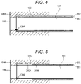
- FIG. 4 is a cross-sectional view illustrating an example of structure of a treatment tool tube 141 according to a comparative example
- Fig. 5 is a cross-sectional view illustrating an example of structure of the treatment tool tube 141 according to the first embodiment.
- the treatment tool tube 141 of the comparative example in Fig. 4 has two-layer structure of an inner layer 201 and an outer layer 202 outside the inner layer.
- the inner layer 201 is formed from polytetrafluoroethylene (PTFE) having solid structure over the entire length (from the distal tip 204 to the hand operation unit 102), and the outer layer 202 is formed from polytetrafluoroethylene (PTFE) having porous structure over the entire length.
- the treatment tool tube 141 is inserted into a hole portion formed in a size corresponding to the outer diameter of the treatment tool tube 141 in the distal-end rigid portion 104M.
- An adhesive 139 is applied between the outer surface of the treatment tool tube 141 and the inner wall of the hole portion, and the treatment tool tube 141 is fixed into the distal-end rigid portion 104M using this adhesive 139.
- the treatment tool tube 141 having two-layer structure of PTFE having solid structure and PTFE having porous structure is inserted into the hole portion of the distal-end rigid portion 104M of the distal tip 104 and fixed using the adhesive 139, the treatment tool tube 141 can be fixed without the outer shape being deformed. Since the outer layer 202 is formed from PTFE having porous structure over the entire length, pliability of the tube can also be ensured.
- the adhesive material 139 needs to be applied to the end portion of the treatment tool tube 141 to prevent air leakage from the end portion of the treatment tool tube 141. For this reason, avoiding such protrusion of the adhesive 139Ais difficult.
- an outer layer 202 of the treatment tool tube 141 of the first embodiment has two-layer structure of an inner layer 201 and the outer layer 202 outside the inner layer.
- the inner layer 201 is formed from PTFE having solid structure over the entire length.
- a first portion 202A positioned at the end portion of the treatment tool tube 141 is formed from PTFE having solid structure.
- a second portion 202B described lastly is formed from PTFE having porous structure.
- both the inner layer 201 and the outer layer 202 are formed from PTFE having solid structure at the end portion of the treatment tool tube 141.
- the outer layer 202 at the end portion of the treatment tool tube 141 is formed from PTFE having solid structure. Therefore, in the process of removal of the adhesive 139A, even if the inner layer 201 at the end portion is damaged, the air leakage does not occur because the outer layer 202 is PTFE having solid structure.
- the outer layer 202 excluding the end portion is formed from PTFE having porous structure, similarly to the comparative example.
- the outer layer 202 is formed from PTFE having porous structure, pliability of the treatment tool tube 141 can be increased, and the flexible tube portion 101 can be flexibly deformed according to a shape of a digestive organ.
- the adhesion strength by the adhesive 139 can be increased by an anchor effect, and thus, the treatment tool tube 141 and the distal-end rigid portion 104M can be firmly connected.
- an endoscope capable of ensuring pliability of a tube while preventing deformation of the tube, occurrence of air leakage, and the like can be provided.
- the second embodiment is different from the first embodiment in structure of a treatment tool tube 141.
- the treatment tool tube 141 includes a first portion 202A formed from PTFE having solid structure and a second portion 202B formed from PTFE having porous structure.
- a third portion 20C having porosity that increases toward the second portion 202B (transition portion) is provided between the first portion 202A and the second portion 202B.
- the third portion 202C extends from the inside of the distal-end rigid portion 104M to the vicinity of the inlet of the hole portion of the distal-end rigid portion 104M.
- the porosity of the third portion 202C is substantially zero in the vicinity of the first portion 202A, but increases toward the second portion 202B, and is substantially the same as the porosity of the second portion 202B in the vicinity of the second portion 202B.
- the third portion 202C at least in part includes PTFE having porous structure, the anchor effect is produced by the adhesive 139, and the distal-end rigid portion 104M can be firmly connected by the adhesive 139.
- the second embodiment can also produce substantially the same effect as that of the first embodiment.
- FIG. 7 The overall configuration of the endoscope system of the third embodiment is substantially the same as that of the first embodiment ( Fig. 1 to Fig. 3 ), and thus duplicate description is omitted below.
- an outer layer 202 of the treatment tool tube 141 includes a first portion 202A formed from PTFE having solid structure, and a second portion 202B2 formed from PTFE having porous structure.
- the outer layer 202 positioned inside the hole portion of the distal-end rigid portion 104M includes, in order from the distal tip 104 side, the first portion 202A, a fourth portion 202B1 formed from PTFE having porous structure, and a fifth portion 202D formed from PTFE having solid structure.
- the fifth portion 202D is provided from the front to the rear of the hole portion of the distal-end rigid portion 104M, and a part of the fifth portion 202D protrudes outward from the hole portion.
- a sixth portion 202C1 having porosity gradually increases is also formed between the fifth portion 202D and the second portion 202B2, a sixth portion 202C1 having porosity gradually increases is also formed.
- the sixth portion 202C1 may be omitted, and the fifth portion 202D having solid structure and the second portion having porous structure may be directly connected.
- the first portion 202A is formed from PTFE having solid structure, whereby the same effect as that of the first embodiment can be obtained.
- the fourth portion 202B1 formed from PTFE having porous structure can firmly connect the treatment tool tube 141 to the distal-end rigid portion 104M.
- the fifth portion 202D formed from PTFE having solid structure is formed from the front to the rear of the hole portion such that it protrudes from the hole portion, and accordingly, the possibility of occurrence of buckling or the like can be reduced even if bending stress is applied to the treatment tool tube 141.
- the treatment tool tube 141 is hardly bent at the root of the hole portion.
- the outer layer 202 from the front to the rear of the inlet of the hole portion is the second portion 202B2 formed from PTFE having porous structure
- the treatment tool tube 141 is easily bent from the root of the hole portion. If forceps F entering and exiting the treatment tool tube 141 come into contact with the bent part, there is a possibility that the inner layer 201 is damaged.
- the fifth portion 202D is provided from the front to the rear of the hole portion, the treatment tool tube 141 is hardly bent at the root, and breakage of the treatment tool tube 141 can be prevented or reduced.
- the present invention is not limited to the above-described embodiments, and includes various modifications.
- the above-described embodiments have been described in detail in order to describe the present invention in an easy-to-understand manner, and the present invention is not necessarily limited to those having all the described configurations.
- a part of the configuration of a certain embodiment can be replaced with the configuration of another embodiment, and the configuration of a certain embodiment can be added to the configuration of another embodiment.
- another configuration can be added to or deleted from a part of the configuration of each embodiment, or a part of the configuration of each embodiment can be replaced with another configuration.
Abstract
Description
- The present invention relates to an endoscope.
- An endoscope device generally includes an insertion portion to be inserted into a body of a subject (such as a digestive organ). The insertion portion internally includes a light guide used for transmitting light and an electric wiring used for transmitting an electric signal from an imaging unit. In addition, the insertion portion internally includes an air and water supply tube used for supplying water or air, and a tube for a treatment tool in/from which a treatment tool may be inserted and removed.
- In a case where such a tube is connected to the distal tip of the endoscope, it is desirable to connect them such that the strength of the tube is not degraded, the outer shape is not deformed, and a step is not formed on the inner surface. It is also required to prevent air leakage due to breakage of the tube or the like. On the other hand, it is desirable that various tubes are pliably deformable.
- It has been difficult for endoscopes that have been conventionally proposed to satisfy the above-mentioned demands for various tubes. For example, in
Patent Literature 1, since structure in which a tube is fitted outside a pipe member is adopted, the outer diameter of the tube is larger and the tube is deformed at a part connected to the pipe member (end portion), leading to an issue that the physical strength of the deformed part is degraded. - On the other hand, in Patent Literature 2, in the structure in which a tube is fitted outside a pipe member similarly, the tube has two-layer structure, and an inner layer is formed from polytetrafluoroethylene (PTFE) having solid structure, and the end portion of an outer layer that is a part to be connected is formed from polytetrafluoroethylene (PTFE) having porous structure. Since the end portion has porous structure, the fitting operation can be performed using smaller force when the tube is fitted outside the pipe member. However, even in this structure, deformation of the outer diameter of the tube is inevitable, and the issue that the physical strength is degraded still occurs.
-
- Patent Literature 1:
JP 7-1630 A - Patent Literature 2:
WO 2008/088087 A - An object of the present invention is to provide an endoscope capable of ensuring pliability of a tube while preventing deformation of the tube, occurrence of air leakage, and the like.
- In order to solve the above-mentioned issue, an endoscope according to the present invention includes an insertion portion and a tube arranged inside the insertion portion. The insertion portion includes a bending section that is bendable based on an operation, a distal tip connected to a distal tip of the bending section, and a flexible tube portion that is bendable by external force independent of the operation, in which the tube includes an inner layer and an outer layer formed outside the inner layer. The inner layer is formed from polytetrafluoroethylene having solid structure, and the outer layer is positioned at an end portion on a side of the distal tip and includes a first portion formed from polytetrafluoroethylene having solid structure and a second portion formed from polytetrafluoroethylene having porous structure.
- According to an endoscope of the present invention, the endoscope capable of ensuring pliability of a tube while preventing deformation of the tube, occurrence of air leakage, and the like can be provided.
-
-
Fig. 1 is an external view of anendoscope system 1 according to a first embodiment of the present invention. -
Fig. 2 is a schematic perspective view illustrating structure of adistal tip 104 part of anendoscope 100. -
Fig. 3 is a cross-sectional view illustrating cross-sectional structure of thedistal tip 104 in detail. -
Fig. 4 is a cross-sectional view illustrating an example of structure of atreatment tool tube 141 according to a comparative example. -
Fig. 5 is a cross-sectional view illustrating an example of structure of atreatment tool tube 141 according to the first embodiment. -
Fig. 6 is a cross-sectional view illustrating an example of structure of atreatment tool tube 141 according to a second embodiment. -
Fig. 7 is a cross-sectional view illustrating an example of structure of atreatment tool tube 141 according to a third embodiment. -
Fig. 8 is a schematic diagram illustrating an effect of the third embodiment. - Hereinafter, the present embodiments will be described with reference to accompanying drawings. In the accompanying drawings, functionally identical elements may be represented by the same number. Note that, although the accompanying drawings illustrate the embodiments and implementation examples conforming to the principles of the present disclosure, these are for understanding the present disclosure and are not used to interpret the present disclosure in a limited manner. The description in this specification is merely exemplary and is not intended to limit the scope of the claims or the application of the present disclosure in any way.
- In the present embodiments, the description is made in sufficient detail for those skilled in the art to make and use the present disclosure, but it is necessary to understand that other implementations and embodiments are possible, and changes in configurations and structure and replacement of various elements are possible without departing from the scope and the spirit of the technical idea of the present disclosure. Therefore, the following description should not be interpreted to limit the present disclosure thereto.
- First, an endoscope system according to a first embodiment of the present invention will be described in detail.
Fig. 1 is an external view of anendoscope system 1 according to the first embodiment, andFig. 2 is a perspective view illustrating structure of adistal tip 104 of anendoscope 100. Theendoscope system 1 substantially includes theendoscope 100, aprocessor 200, alight source device 300, a water andair supply unit 400, asuction unit 500, adisplay 600, and aninput unit 700. - The
endoscope 100 is configured to be insertable into a body of a subject and has a function of imaging an object and transmitting an image signal of the image captured by the imaging to theprocessor 200. Theprocessor 200 receives the image signal from theendoscope 100 and performs predetermined signal processing. - The
light source device 300 is configured to be connectable to theprocessor 200, and internally includes a light source that emits irradiation light used for irradiating an object. The light from the light source is emitted toward a subject through light guides to be described below. Thelight source device 300 may be configured separately from theprocessor 200 and configured to be connectable to theprocessor 200, or may be incorporated inside theprocessor 200. - The water and
air supply unit 400 includes an air pump and a water flow pump (not illustrated) used for discharging a water flow or an air flow supplied to a subject. Thesuction unit 500 includes a pump and a tank (not illustrated) used for sucking a body fluid or an excision sucked from a body of a subject through aninsertion portion 101. - The
display 600 is a display device for displaying based on, for example, result of data processing by theprocessor 200. Theinput unit 700 is a device for inputting an instruction from an operator in various measurement operations. - The
endoscope 100 includes theinsertion portion 10, ahand operation unit 102, auniversal cable 105, and aconnector unit 106. Theinsertion portion 10 includes aflexible tube portion 101, a connecting portion 103A, abending section 103, and thedistal tip 104. - As illustrated in
Fig. 1 , theinsertion portion 10 of theendoscope 100 has flexibility and includes theflexible tube portion 101 to be inserted into a body of a subject. One end of theflexible tube portion 101 is connected to thehand operation unit 102. Thehand operation unit 102 includes, for example, abending operation knob 102A and other operation units that can be operated by a user, and is a portion for allowing an operator to perform various operations for imaging by theendoscope system 1. Note that thehand operation unit 102 includes a treatmenttool insertion port 102B through which a treatment tool may be inserted. - Of the
flexible tube portion 101, a portion close to thebending section 103 is a firstflexible tube portion 101A, and a portion close to thehand operation unit 102 is a secondflexible tube portion 101B. While the shape of thebending section 103 can be actively changed by an operation of thebending operation knob 102A by an operator, the firstflexible tube portion 101A is a portion having a shape that is passively changed by external force independent of the operation of thebending operation knob 102A, for example, external force caused by thedistal tip 104 or thebending section 103 hitting the wall surface of a digestive organ. The same applies to the secondflexible tube portion 101B, but the degree of change in shape is smaller (the maximum curvature radius is larger) than that of the firstflexible tube portion 101A. Note that, in the example ofFig. 1 , theflexible tube portion 101 includes two types of flexible tube portions, but the present invention is not limited thereto, and three or more types of flexible tube portions may be provided, or one type may be provided. - At the distal tip of the
flexible tube portion 101, a bending section 103 (active bending section) configured to be bendable is provided. As described above, thebending section 103 is bent by being pulled by an operation wire (not illustrated inFig. 1 ) linked with a rotation operation of the bendingoperation knob 102A provided on thehand operation unit 102. Note that a connecting portion that is not deformed by bending wires W or external force may be provided between the bendingsection 103 and the firstflexible tube portion 101A. - To the distal tip of the
bending section 103, thedistal tip 104 including an image sensor (imaging unit) is connected. Change of the direction of thedistal tip 104 according to a bending operation of thebending section 103 by a rotation operation of the bendingoperation knob 102A can change the imaging region by theendoscope 100. - From the opposite side of the
hand operation unit 102, theuniversal cable 105 extends toward theconnector unit 106. Similarly to theinsertion portion 10, theuniversal cable 105 internally includes the light guides, various wirings, and various tubes. - The
connector unit 106 includes various connectors for connecting theendoscope 100 to theprocessor 200. In addition, theconnector unit 106 includes a water andair supply tube 108 as a path through which a water flow and an air flow are sent toward theinsertion portion 10. - The structure of the
distal tip 104 of theendoscope 100 will be described with reference toFig. 2 .Light distribution lenses distal tip 104 of theendoscope 100, and light guides LGa and LGb extend from thedistal tip 104 to theconnector unit 106 inside theflexible tube portion 101. Light from the light source of thelight source device 300 is guided by the light guides LGa and LGb, and is emitted toward a subject by thelight distribution lenses distal tip 104. - Furthermore, as illustrated in
Fig. 2 , theendoscope 100 includes anobjective lens 113 and animage sensor 133 in thedistal tip 104. Theobjective lens 113 provided on thedistal tip 104 condenses scattered light or reflected light from a subject to form an image of the subject on the light receiving surface of theimage sensor 133. - The
image sensor 133 may be formed by using, for example, a charge coupled device (CCD) or a complementary metal oxide semiconductor sensor (CMOS sensor). Theimage sensor 133 is controlled by a signal (gain control signal, exposure control signal, shutter speed control signal, and the like) supplied from theprocessor 200 via anelectric wiring 138, and supplies an image signal of a captured image to theprocessor 200 via theelectric wiring 138 and an A/D conversion circuit (not illustrated). - In addition, on the end surface of the
distal tip 104, an air and water supply port 114 (nozzle), a subwater supply port 115, and atreatment tool port 116 are provided as end portions or openings of various tubes. The air andwater supply port 114 is connected to an air andwater supply tube 121 in order to introduce a water flow or an air flow used for, for example, cleaning thedistal tip 104. - The sub
water supply port 115 is connected to a subwater supply tube 122 in order to introduce a sub water supply used for removing wastes in the field of view. Thetubes distal tip 104, thebending section 103, theflexible tube portion 101, thehand operation unit 102, and theuniversal cable 105. - In addition to
such tubes treatment tool tube 141 is provided inside theendoscope 100. Thetreatment tool tube 141 is arranged such that a treatment tool such as forceps can be freely moved forward and backward inside thetreatment tool tube 141. The distal tip of thetreatment tool tube 141 forms thetreatment tool port 116 in thedistal tip 104. - The cross-sectional structure of the
distal tip 104 will be described in more detail with reference toFig. 3 . This cross-sectional view illustrates details of the structure of theobjective lens 113 to theelectric wiring 138, the air andwater supply tube 121, and thetreatment tool tube 141. The structure of thelight distribution lenses water supply tube 122 is also not illustrated. - The
distal tip 104 includes a distal-endrigid portion 104M. The distal-endrigid portion 104M includes hole portions forming the air andwater supply port 114, the subwater supply port 115, and thetreatment tool port 116 described above. As illustrated inFig. 3 , the air andwater supply tube 121 and thetreatment tool tube 141 are inserted into corresponding hole portions of the distal-endrigid portion 104M. - The distal-end
rigid portion 104M also includes a hole portion into which alens frame 136 holding theobjective lens 113, a diaphragm AP, and a light-shieldingmask 131 is fitted. Thelens frame 136 is fixed into the hole portion of the distal-endrigid portion 104M via asealant 137. - On the other hand, for example, the light-shielding
mask 131, acover glass 132, the image sensor (CCD) 133, and acircuit board 134 are held behind theobjective lens 113 by aCCD unit frame 135, and theCCD unit frame 135 is inserted and fixed into the hole portion of the distal-endrigid portion 104M. Theelectric wiring 138 is connected to thecircuit board 134. - The distal tip 104 (distal-end
rigid portion 104M) formed as described above is fitted to the distal tip of thebending section 103. Thebending section 103 includes bendingpieces 153 formed in a substantially cylindrical shape connected to each other in a rotatable manner by rivets. The outer surfaces of the bendingpieces 153 are covered with areticular tube 152. The end portion of thereticular tube 152 is joined to the distal-endrigid portion 104M through an adjoiningannular tube 151. The outer surface of thereticular tube 152 is covered with a synthetic resin outercover rubber tube 155. The end portions of the outercover rubber tube 155 and the distal-endrigid portion 104M are fixed by, for example, a fixing string S1. - Wire guides 154 are provided between a plurality of the bending
pieces 153, and the bending wires W used for a bending operation pass through the wire guides 154. For example, the number of the bending wires W is four and the four bending wires W are provided at substantially equal intervals in the circumferential direction in oneflexible tube portion 101. An end of each of the bending wires W is fixed to thefrontmost bending piece 153. Thebending section 103 is bent when the other end of each of the bending wires W is tensioned or relaxed by the operation of the bendingoperation knob 102A. - An example of structure of the
treatment tool tube 141 will be described with reference toFig. 4 and Fig. 5. Fig. 4 is a cross-sectional view illustrating an example of structure of atreatment tool tube 141 according to a comparative example, andFig. 5 is a cross-sectional view illustrating an example of structure of thetreatment tool tube 141 according to the first embodiment. - The
treatment tool tube 141 of the comparative example inFig. 4 has two-layer structure of aninner layer 201 and anouter layer 202 outside the inner layer. Theinner layer 201 is formed from polytetrafluoroethylene (PTFE) having solid structure over the entire length (from the distal tip 204 to the hand operation unit 102), and theouter layer 202 is formed from polytetrafluoroethylene (PTFE) having porous structure over the entire length. Thetreatment tool tube 141 is inserted into a hole portion formed in a size corresponding to the outer diameter of thetreatment tool tube 141 in the distal-endrigid portion 104M. An adhesive 139 is applied between the outer surface of thetreatment tool tube 141 and the inner wall of the hole portion, and thetreatment tool tube 141 is fixed into the distal-endrigid portion 104M using this adhesive 139. - In a case where such
treatment tool tube 141 having two-layer structure of PTFE having solid structure and PTFE having porous structure is inserted into the hole portion of the distal-endrigid portion 104M of thedistal tip 104 and fixed using the adhesive 139, thetreatment tool tube 141 can be fixed without the outer shape being deformed. Since theouter layer 202 is formed from PTFE having porous structure over the entire length, pliability of the tube can also be ensured. - However, in a case of the structure of the comparative example in
Fig. 4 , when protrusion of an adhesive 139A occurs at the end portion of thetreatment tool tube 141, there is an issue that removal of the protrusion is hindered. In a case where such protrusion of the adhesive 139A occurs, removal of the protrusion using a tool may be necessary. However, theinner layer 201 may be damaged in the process of the removal, and theouter layer 202 may be exposed. In this case, there is a possibility that air leakage from the exposed part of theouter layer 202 occurs. - In a case of the structure in
Fig. 4 , theadhesive material 139 needs to be applied to the end portion of thetreatment tool tube 141 to prevent air leakage from the end portion of thetreatment tool tube 141. For this reason, avoiding such protrusion of the adhesive 139Ais difficult. - Meanwhile, similarly to the comparative example, an
outer layer 202 of thetreatment tool tube 141 of the first embodiment has two-layer structure of aninner layer 201 and theouter layer 202 outside the inner layer. Similarly to the comparative example, theinner layer 201 is formed from PTFE having solid structure over the entire length. - However, as for the
outer layer 202, unlike the comparative example, afirst portion 202A positioned at the end portion of thetreatment tool tube 141 is formed from PTFE having solid structure. Asecond portion 202B described lastly is formed from PTFE having porous structure. In other words, both theinner layer 201 and theouter layer 202 are formed from PTFE having solid structure at the end portion of thetreatment tool tube 141. - According to the configuration of the first embodiment, even if protrusion of the adhesive 139A occurs, there is no possibility that the air leakage occurs as in the comparative example. Similarly to the
inner layer 201, theouter layer 202 at the end portion of thetreatment tool tube 141 is formed from PTFE having solid structure. Therefore, in the process of removal of the adhesive 139A, even if theinner layer 201 at the end portion is damaged, the air leakage does not occur because theouter layer 202 is PTFE having solid structure. - On the other hand, the
outer layer 202 excluding the end portion (second portion 202B) is formed from PTFE having porous structure, similarly to the comparative example. In a case where theouter layer 202 is formed from PTFE having porous structure, pliability of thetreatment tool tube 141 can be increased, and theflexible tube portion 101 can be flexibly deformed according to a shape of a digestive organ. In addition, the adhesion strength by the adhesive 139 can be increased by an anchor effect, and thus, thetreatment tool tube 141 and the distal-endrigid portion 104M can be firmly connected. - As described above, according to the
treatment tool tube 141 of the first embodiment, an endoscope capable of ensuring pliability of a tube while preventing deformation of the tube, occurrence of air leakage, and the like can be provided. - Next, an endoscope system according to a second embodiment will be described with reference to
Fig. 6 . The overall configuration of the endoscope system of the second embodiment is substantially the same as that of the first embodiment (Fig. 1 to Fig. 3 ), and thus duplicate description is omitted below. - As illustrated in
Fig. 6 , the second embodiment is different from the first embodiment in structure of atreatment tool tube 141. Similarly to the first embodiment, thetreatment tool tube 141 includes afirst portion 202A formed from PTFE having solid structure and asecond portion 202B formed from PTFE having porous structure. However, between thefirst portion 202A and thesecond portion 202B, a third portion 20C having porosity that increases toward thesecond portion 202B (transition portion) is provided. For example, thethird portion 202C extends from the inside of the distal-endrigid portion 104M to the vicinity of the inlet of the hole portion of the distal-endrigid portion 104M. - The porosity of the
third portion 202C is substantially zero in the vicinity of thefirst portion 202A, but increases toward thesecond portion 202B, and is substantially the same as the porosity of thesecond portion 202B in the vicinity of thesecond portion 202B. As described above, since thethird portion 202C at least in part includes PTFE having porous structure, the anchor effect is produced by the adhesive 139, and the distal-endrigid portion 104M can be firmly connected by the adhesive 139. - The second embodiment can also produce substantially the same effect as that of the first embodiment.
- Next, an endoscope system according to a third embodiment will be described with reference to
Fig. 7 . The overall configuration of the endoscope system of the third embodiment is substantially the same as that of the first embodiment (Fig. 1 to Fig. 3 ), and thus duplicate description is omitted below. - As illustrated in
Fig. 7 , the third embodiment is different from the first embodiment in structure of atreatment tool tube 141. Similarly to the first embodiment, anouter layer 202 of thetreatment tool tube 141 includes afirst portion 202A formed from PTFE having solid structure, and a second portion 202B2 formed from PTFE having porous structure. - However, the
outer layer 202 positioned inside the hole portion of the distal-endrigid portion 104M includes, in order from thedistal tip 104 side, thefirst portion 202A, a fourth portion 202B1 formed from PTFE having porous structure, and afifth portion 202D formed from PTFE having solid structure. Thefifth portion 202D is provided from the front to the rear of the hole portion of the distal-endrigid portion 104M, and a part of thefifth portion 202D protrudes outward from the hole portion. - Note that, in the example illustrated in
Fig. 7 , between thefifth portion 202D and the second portion 202B2, a sixth portion 202C1 having porosity gradually increases is also formed. The sixth portion 202C1 may be omitted, and thefifth portion 202D having solid structure and the second portion having porous structure may be directly connected. - According to the structure of the third embodiment, the
first portion 202A is formed from PTFE having solid structure, whereby the same effect as that of the first embodiment can be obtained. In addition, the fourth portion 202B1 formed from PTFE having porous structure can firmly connect thetreatment tool tube 141 to the distal-endrigid portion 104M. - Adjacent to the fourth portion 202B1, the
fifth portion 202D formed from PTFE having solid structure is formed from the front to the rear of the hole portion such that it protrudes from the hole portion, and accordingly, the possibility of occurrence of buckling or the like can be reduced even if bending stress is applied to thetreatment tool tube 141. - In addition, since the
fifth portion 202D is provided from the front to the rear of the hole portion, thetreatment tool tube 141 is hardly bent at the root of the hole portion. As illustrated inFig. 8 , in a case where theouter layer 202 from the front to the rear of the inlet of the hole portion is the second portion 202B2 formed from PTFE having porous structure, thetreatment tool tube 141 is easily bent from the root of the hole portion. If forceps F entering and exiting thetreatment tool tube 141 come into contact with the bent part, there is a possibility that theinner layer 201 is damaged. On the other hand, in the fifth embodiment, since thefifth portion 202D is provided from the front to the rear of the hole portion, thetreatment tool tube 141 is hardly bent at the root, and breakage of thetreatment tool tube 141 can be prevented or reduced. - The present invention is not limited to the above-described embodiments, and includes various modifications. For example, the above-described embodiments have been described in detail in order to describe the present invention in an easy-to-understand manner, and the present invention is not necessarily limited to those having all the described configurations. A part of the configuration of a certain embodiment can be replaced with the configuration of another embodiment, and the configuration of a certain embodiment can be added to the configuration of another embodiment. In addition, another configuration can be added to or deleted from a part of the configuration of each embodiment, or a part of the configuration of each embodiment can be replaced with another configuration.
-
- 1
- Endoscope system
- 100
- Endoscope
- 10
- Insertion portion
- 101
- Flexible tube portion
- 101
- AFirst flexible tube portion
- 101B
- Second flexible tube portion
- 102
- Hand operation unit
- 102A
- Bending operation knob
- 103
- Bending section
- 104
- Distal tip
- 104M
- Distal-end rigid portion
- 105
- Universal cable
- 106
- Connector unit
- 108
- Water and air supply tube
- 109
- Suction tube
- LGa,
- LGb Light guide
- 112A, 112B
- Light distribution lens
- 113
- Objective lens
- 114
- Air and water supply port
- 115
- Sub water supply port
- 116
- Treatment tool port
- 121
- Air and water supply tube
- 122
- Sub water supply tube
- 141
- Treatment tool tube
- 133
- Image sensor
- 134
- Circuit board
- 135
- CCD unit frame
- 136
- Lens frame
- 137
- Sealant
- 138
- Electric wiring
- 200
- Processor
- 201
- Inner layer
- 202
- Outer layer
- 300
- Light source device
- 400
- Water and air supply unit
- 500
- Suction unit
- 600
- Display
- 700
- Input unit.
Claims (8)
- An endoscope comprising:an insertion portion; anda tube arranged inside the insertion portion, whereinthe insertion portion includesa bending section that is bendable based on an operationa distal tip connected to a distal tip of the bending section anda flexible tube portion that is bendable by external force independent of the operation,the tube includes an inner layer and an outer layer formed outside the inner layer,the inner layer is formed from polytetrafluoroethylene having solid structure, andthe outer layer is positioned at an end portion on a side of the distal tip and includes a first portion formed from polytetrafluoroethylene having solid structure and a second portion formed from polytetrafluoroethylene having porous structure.
- The endoscope according to claim 1, wherein the distal tip includes a hole portion into which the tube is insertable, and the tube is fixed into the distal tip using an adhesive.
- The endoscope according to claim 1 or 2, wherein the second portion is formed at a position in contact with the distal tip.
- The endoscope according to claim 1 or 2, wherein the outer layer includes, between the first portion and the second portion, a third portion having porosity that increases toward the second portion.
- The endoscope according to claim 4, wherein the third portion is formed at a position in contact with the distal tip.
- The endoscope according to claim 1 or 2, wherein the outer layer includes, in order from an end portion on a side of the distal tip, the first portion, a fourth portion formed from polytetrafluoroethylene having porous structure, and a fifth portion formed from polytetrafluoroethylene having solid structure.
- The endoscope according to claim 6, whereinthe fourth portion is formed at a position in contact with the distal tip, andthe fifth portion is formed at a position where the fifth portion protrudes from an inlet of the distal tip.
- The endoscope according to claim 6, wherein the outer layer includes, between the fifth portion and the second portion, a sixth portion having porosity that increases toward the second portion.
Applications Claiming Priority (2)
| Application Number | Priority Date | Filing Date | Title |
|---|---|---|---|
| JP2019187020A JP7364414B2 (en) | 2019-10-10 | 2019-10-10 | Endoscope |
| PCT/JP2020/037102 WO2021070697A1 (en) | 2019-10-10 | 2020-09-30 | Endoscope |
Publications (4)
| Publication Number | Publication Date |
|---|---|
| EP4042926A1 true EP4042926A1 (en) | 2022-08-17 |
| EP4042926A4 EP4042926A4 (en) | 2023-10-11 |
| EP4042926C0 EP4042926C0 (en) | 2024-03-20 |
| EP4042926B1 EP4042926B1 (en) | 2024-03-20 |
Family
ID=75437890
Family Applications (1)
| Application Number | Title | Priority Date | Filing Date |
|---|---|---|---|
| EP20873553.0A Active EP4042926B1 (en) | 2019-10-10 | 2020-09-30 | Endoscope |
Country Status (5)
| Country | Link |
|---|---|
| US (1) | US20220287585A1 (en) |
| EP (1) | EP4042926B1 (en) |
| JP (1) | JP7364414B2 (en) |
| CN (1) | CN114554928A (en) |
| WO (1) | WO2021070697A1 (en) |
Family Cites Families (9)
| Publication number | Priority date | Publication date | Assignee | Title |
|---|---|---|---|---|
| JP3184387B2 (en) | 1992-12-25 | 2001-07-09 | ジャパンゴアテックス株式会社 | Flexible multilayer tube |
| JP3808246B2 (en) * | 1999-08-09 | 2006-08-09 | オリンパス株式会社 | Endoscope |
| US20100256445A1 (en) * | 2006-12-07 | 2010-10-07 | International Polymer Engineering, Inc. | Endoscopic Working Channel and Method of Making Same |
| JP4905785B2 (en) | 2007-01-18 | 2012-03-28 | 日立工機株式会社 | Electric tool |
| CN102781302B (en) | 2010-07-05 | 2015-05-06 | 奥林巴斯医疗株式会社 | Tube to be disposed in endoscope, and endoscope |
| JP5787701B2 (en) | 2011-09-30 | 2015-09-30 | 三菱重工業株式会社 | Wave power reduction structure |
| WO2016052208A1 (en) | 2014-10-03 | 2016-04-07 | オリンパス株式会社 | Insertion part of insertion device and insertion device |
| WO2018088087A1 (en) | 2016-11-09 | 2018-05-17 | オリンパス株式会社 | Endoscope |
| WO2018220867A1 (en) * | 2017-06-01 | 2018-12-06 | Hoya株式会社 | Endoscope |
-
2019
- 2019-10-10 JP JP2019187020A patent/JP7364414B2/en active Active
-
2020
- 2020-09-30 US US17/765,678 patent/US20220287585A1/en active Pending
- 2020-09-30 EP EP20873553.0A patent/EP4042926B1/en active Active
- 2020-09-30 WO PCT/JP2020/037102 patent/WO2021070697A1/en unknown
- 2020-09-30 CN CN202080070696.9A patent/CN114554928A/en active Pending
Also Published As
| Publication number | Publication date |
|---|---|
| JP7364414B2 (en) | 2023-10-18 |
| JP2021061912A (en) | 2021-04-22 |
| EP4042926C0 (en) | 2024-03-20 |
| WO2021070697A1 (en) | 2021-04-15 |
| US20220287585A1 (en) | 2022-09-15 |
| EP4042926B1 (en) | 2024-03-20 |
| CN114554928A (en) | 2022-05-27 |
| EP4042926A4 (en) | 2023-10-11 |
Similar Documents
| Publication | Publication Date | Title |
|---|---|---|
| KR101556881B1 (en) | Endoscope | |
| US10682047B2 (en) | Tracheal tube | |
| JP5390048B1 (en) | Endoscope system | |
| EP2896348A1 (en) | Endoscope cleaning sheath and endoscope device | |
| JP2009201973A (en) | Endoscope | |
| EP4042926A1 (en) | Endoscope | |
| EP4062820B1 (en) | Endoscope | |
| KR101637846B1 (en) | Endoscope | |
| JP7201829B2 (en) | Endoscope | |
| EP4047409A1 (en) | Endoscope | |
| US20220409854A1 (en) | Multifunctional catheter | |
| CN105411506A (en) | Endoscope-used shield and endoscope system | |
| CN212214357U (en) | Multifunctional catheter | |
| JP6850694B2 (en) | Endoscope and manufacturing method of endoscope | |
| JPH07308283A (en) | Cover type endoscope | |
| US9220397B2 (en) | Endoscope | |
| JPH10309259A (en) | Endoscope | |
| EP3199090A1 (en) | Endoscope flexible tube | |
| WO2023148901A1 (en) | Endoscope and tip body | |
| US20220296089A1 (en) | Endoscope, distal end portion of endoscope, and insertion portion of endoscope | |
| US20230190082A1 (en) | Endoscope and endoscope system | |
| WO2016031280A1 (en) | Endoscope and endoscopic system provided with said endoscope | |
| JP2023128308A (en) | Endoscope | |
| JP2017225746A (en) | Endoscope | |
| JP2009183333A (en) | Endoscope for medical checkup |
Legal Events
| Date | Code | Title | Description |
|---|---|---|---|
| STAA | Information on the status of an ep patent application or granted ep patent |
Free format text: STATUS: THE INTERNATIONAL PUBLICATION HAS BEEN MADE |
|
| PUAI | Public reference made under article 153(3) epc to a published international application that has entered the european phase |
Free format text: ORIGINAL CODE: 0009012 |
|
| STAA | Information on the status of an ep patent application or granted ep patent |
Free format text: STATUS: REQUEST FOR EXAMINATION WAS MADE |
|
| 17P | Request for examination filed |
Effective date: 20220407 |
|
| AK | Designated contracting states |
Kind code of ref document: A1 Designated state(s): AL AT BE BG CH CY CZ DE DK EE ES FI FR GB GR HR HU IE IS IT LI LT LU LV MC MK MT NL NO PL PT RO RS SE SI SK SM TR |
|
| DAV | Request for validation of the european patent (deleted) | ||
| DAX | Request for extension of the european patent (deleted) | ||
| A4 | Supplementary search report drawn up and despatched |
Effective date: 20230907 |
|
| RIC1 | Information provided on ipc code assigned before grant |
Ipc: G02B 23/24 20060101ALI20230901BHEP Ipc: A61B 1/018 20060101ALI20230901BHEP Ipc: A61B 1/005 20060101ALI20230901BHEP Ipc: A61B 1/00 20060101AFI20230901BHEP |
|
| GRAP | Despatch of communication of intention to grant a patent |
Free format text: ORIGINAL CODE: EPIDOSNIGR1 |
|
| STAA | Information on the status of an ep patent application or granted ep patent |
Free format text: STATUS: GRANT OF PATENT IS INTENDED |
|
| INTG | Intention to grant announced |
Effective date: 20231208 |
|
| GRAS | Grant fee paid |
Free format text: ORIGINAL CODE: EPIDOSNIGR3 |
|
| GRAA | (expected) grant |
Free format text: ORIGINAL CODE: 0009210 |
|
| STAA | Information on the status of an ep patent application or granted ep patent |
Free format text: STATUS: THE PATENT HAS BEEN GRANTED |
|
| AK | Designated contracting states |
Kind code of ref document: B1 Designated state(s): AL AT BE BG CH CY CZ DE DK EE ES FI FR GB GR HR HU IE IS IT LI LT LU LV MC MK MT NL NO PL PT RO RS SE SI SK SM TR |
|
| REG | Reference to a national code |
Ref country code: GB Ref legal event code: FG4D |
|
| REG | Reference to a national code |
Ref country code: CH Ref legal event code: EP |
|
| REG | Reference to a national code |
Ref country code: DE Ref legal event code: R096 Ref document number: 602020027694 Country of ref document: DE |
|
| U01 | Request for unitary effect filed |
Effective date: 20240325 |
|
| U07 | Unitary effect registered |
Designated state(s): AT BE BG DE DK EE FI FR IT LT LU LV MT NL PT SE SI Effective date: 20240403 |