EP4041992B1 - Injecteur pour une turbine haute pression - Google Patents
Injecteur pour une turbine haute pression Download PDFInfo
- Publication number
- EP4041992B1 EP4041992B1 EP20793763.2A EP20793763A EP4041992B1 EP 4041992 B1 EP4041992 B1 EP 4041992B1 EP 20793763 A EP20793763 A EP 20793763A EP 4041992 B1 EP4041992 B1 EP 4041992B1
- Authority
- EP
- European Patent Office
- Prior art keywords
- channel
- section
- injector
- injector according
- outlet
- Prior art date
- Legal status (The legal status is an assumption and is not a legal conclusion. Google has not performed a legal analysis and makes no representation as to the accuracy of the status listed.)
- Active
Links
Images

Classifications
-
- F—MECHANICAL ENGINEERING; LIGHTING; HEATING; WEAPONS; BLASTING
- F01—MACHINES OR ENGINES IN GENERAL; ENGINE PLANTS IN GENERAL; STEAM ENGINES
- F01D—NON-POSITIVE DISPLACEMENT MACHINES OR ENGINES, e.g. STEAM TURBINES
- F01D5/00—Blades; Blade-carrying members; Heating, heat-insulating, cooling or antivibration means on the blades or the members
- F01D5/02—Blade-carrying members, e.g. rotors
- F01D5/08—Heating, heat-insulating or cooling means
- F01D5/081—Cooling fluid being directed on the side of the rotor disc or at the roots of the blades
- F01D5/082—Cooling fluid being directed on the side of the rotor disc or at the roots of the blades on the side of the rotor disc
-
- B—PERFORMING OPERATIONS; TRANSPORTING
- B22—CASTING; POWDER METALLURGY
- B22F—WORKING METALLIC POWDER; MANUFACTURE OF ARTICLES FROM METALLIC POWDER; MAKING METALLIC POWDER; APPARATUS OR DEVICES SPECIALLY ADAPTED FOR METALLIC POWDER
- B22F10/00—Additive manufacturing of workpieces or articles from metallic powder
- B22F10/20—Direct sintering or melting
-
- B—PERFORMING OPERATIONS; TRANSPORTING
- B22—CASTING; POWDER METALLURGY
- B22F—WORKING METALLIC POWDER; MANUFACTURE OF ARTICLES FROM METALLIC POWDER; MAKING METALLIC POWDER; APPARATUS OR DEVICES SPECIALLY ADAPTED FOR METALLIC POWDER
- B22F10/00—Additive manufacturing of workpieces or articles from metallic powder
- B22F10/20—Direct sintering or melting
- B22F10/28—Powder bed fusion, e.g. selective laser melting [SLM] or electron beam melting [EBM]
-
- B—PERFORMING OPERATIONS; TRANSPORTING
- B22—CASTING; POWDER METALLURGY
- B22F—WORKING METALLIC POWDER; MANUFACTURE OF ARTICLES FROM METALLIC POWDER; MAKING METALLIC POWDER; APPARATUS OR DEVICES SPECIALLY ADAPTED FOR METALLIC POWDER
- B22F5/00—Manufacture of workpieces or articles from metallic powder characterised by the special shape of the product
- B22F5/009—Manufacture of workpieces or articles from metallic powder characterised by the special shape of the product of turbine components other than turbine blades
-
- B—PERFORMING OPERATIONS; TRANSPORTING
- B33—ADDITIVE MANUFACTURING TECHNOLOGY
- B33Y—ADDITIVE MANUFACTURING, i.e. MANUFACTURING OF THREE-DIMENSIONAL [3D] OBJECTS BY ADDITIVE DEPOSITION, ADDITIVE AGGLOMERATION OR ADDITIVE LAYERING, e.g. BY 3D PRINTING, STEREOLITHOGRAPHY OR SELECTIVE LASER SINTERING
- B33Y80/00—Products made by additive manufacturing
-
- F—MECHANICAL ENGINEERING; LIGHTING; HEATING; WEAPONS; BLASTING
- F01—MACHINES OR ENGINES IN GENERAL; ENGINE PLANTS IN GENERAL; STEAM ENGINES
- F01D—NON-POSITIVE DISPLACEMENT MACHINES OR ENGINES, e.g. STEAM TURBINES
- F01D5/00—Blades; Blade-carrying members; Heating, heat-insulating, cooling or antivibration means on the blades or the members
- F01D5/02—Blade-carrying members, e.g. rotors
- F01D5/08—Heating, heat-insulating or cooling means
- F01D5/081—Cooling fluid being directed on the side of the rotor disc or at the roots of the blades
-
- F—MECHANICAL ENGINEERING; LIGHTING; HEATING; WEAPONS; BLASTING
- F02—COMBUSTION ENGINES; HOT-GAS OR COMBUSTION-PRODUCT ENGINE PLANTS
- F02C—GAS-TURBINE PLANTS; AIR INTAKES FOR JET-PROPULSION PLANTS; CONTROLLING FUEL SUPPLY IN AIR-BREATHING JET-PROPULSION PLANTS
- F02C7/00—Features, components parts, details or accessories, not provided for in, or of interest apart form groups F02C1/00 - F02C6/00; Air intakes for jet-propulsion plants
- F02C7/12—Cooling of plants
- F02C7/16—Cooling of plants characterised by cooling medium
- F02C7/18—Cooling of plants characterised by cooling medium the medium being gaseous, e.g. air
-
- F—MECHANICAL ENGINEERING; LIGHTING; HEATING; WEAPONS; BLASTING
- F05—INDEXING SCHEMES RELATING TO ENGINES OR PUMPS IN VARIOUS SUBCLASSES OF CLASSES F01-F04
- F05B—INDEXING SCHEME RELATING TO WIND, SPRING, WEIGHT, INERTIA OR LIKE MOTORS, TO MACHINES OR ENGINES FOR LIQUIDS COVERED BY SUBCLASSES F03B, F03D AND F03G
- F05B2250/00—Geometry
- F05B2250/30—Arrangement of components
- F05B2250/32—Arrangement of components according to their shape
- F05B2250/323—Arrangement of components according to their shape convergent
-
- F—MECHANICAL ENGINEERING; LIGHTING; HEATING; WEAPONS; BLASTING
- F05—INDEXING SCHEMES RELATING TO ENGINES OR PUMPS IN VARIOUS SUBCLASSES OF CLASSES F01-F04
- F05D—INDEXING SCHEME FOR ASPECTS RELATING TO NON-POSITIVE-DISPLACEMENT MACHINES OR ENGINES, GAS-TURBINES OR JET-PROPULSION PLANTS
- F05D2220/00—Application
- F05D2220/30—Application in turbines
- F05D2220/32—Application in turbines in gas turbines
- F05D2220/323—Application in turbines in gas turbines for aircraft propulsion, e.g. jet engines
-
- F—MECHANICAL ENGINEERING; LIGHTING; HEATING; WEAPONS; BLASTING
- F05—INDEXING SCHEMES RELATING TO ENGINES OR PUMPS IN VARIOUS SUBCLASSES OF CLASSES F01-F04
- F05D—INDEXING SCHEME FOR ASPECTS RELATING TO NON-POSITIVE-DISPLACEMENT MACHINES OR ENGINES, GAS-TURBINES OR JET-PROPULSION PLANTS
- F05D2230/00—Manufacture
- F05D2230/20—Manufacture essentially without removing material
- F05D2230/22—Manufacture essentially without removing material by sintering
-
- F—MECHANICAL ENGINEERING; LIGHTING; HEATING; WEAPONS; BLASTING
- F05—INDEXING SCHEMES RELATING TO ENGINES OR PUMPS IN VARIOUS SUBCLASSES OF CLASSES F01-F04
- F05D—INDEXING SCHEME FOR ASPECTS RELATING TO NON-POSITIVE-DISPLACEMENT MACHINES OR ENGINES, GAS-TURBINES OR JET-PROPULSION PLANTS
- F05D2230/00—Manufacture
- F05D2230/20—Manufacture essentially without removing material
- F05D2230/23—Manufacture essentially without removing material by permanently joining parts together
- F05D2230/232—Manufacture essentially without removing material by permanently joining parts together by welding
- F05D2230/234—Laser welding
-
- F—MECHANICAL ENGINEERING; LIGHTING; HEATING; WEAPONS; BLASTING
- F05—INDEXING SCHEMES RELATING TO ENGINES OR PUMPS IN VARIOUS SUBCLASSES OF CLASSES F01-F04
- F05D—INDEXING SCHEME FOR ASPECTS RELATING TO NON-POSITIVE-DISPLACEMENT MACHINES OR ENGINES, GAS-TURBINES OR JET-PROPULSION PLANTS
- F05D2230/00—Manufacture
- F05D2230/30—Manufacture with deposition of material
- F05D2230/31—Layer deposition
-
- F—MECHANICAL ENGINEERING; LIGHTING; HEATING; WEAPONS; BLASTING
- F05—INDEXING SCHEMES RELATING TO ENGINES OR PUMPS IN VARIOUS SUBCLASSES OF CLASSES F01-F04
- F05D—INDEXING SCHEME FOR ASPECTS RELATING TO NON-POSITIVE-DISPLACEMENT MACHINES OR ENGINES, GAS-TURBINES OR JET-PROPULSION PLANTS
- F05D2250/00—Geometry
- F05D2250/10—Two-dimensional
- F05D2250/11—Two-dimensional triangular
-
- F—MECHANICAL ENGINEERING; LIGHTING; HEATING; WEAPONS; BLASTING
- F05—INDEXING SCHEMES RELATING TO ENGINES OR PUMPS IN VARIOUS SUBCLASSES OF CLASSES F01-F04
- F05D—INDEXING SCHEME FOR ASPECTS RELATING TO NON-POSITIVE-DISPLACEMENT MACHINES OR ENGINES, GAS-TURBINES OR JET-PROPULSION PLANTS
- F05D2250/00—Geometry
- F05D2250/10—Two-dimensional
- F05D2250/12—Two-dimensional rectangular
-
- F—MECHANICAL ENGINEERING; LIGHTING; HEATING; WEAPONS; BLASTING
- F05—INDEXING SCHEMES RELATING TO ENGINES OR PUMPS IN VARIOUS SUBCLASSES OF CLASSES F01-F04
- F05D—INDEXING SCHEME FOR ASPECTS RELATING TO NON-POSITIVE-DISPLACEMENT MACHINES OR ENGINES, GAS-TURBINES OR JET-PROPULSION PLANTS
- F05D2250/00—Geometry
- F05D2250/10—Two-dimensional
- F05D2250/13—Two-dimensional trapezoidal
-
- F—MECHANICAL ENGINEERING; LIGHTING; HEATING; WEAPONS; BLASTING
- F05—INDEXING SCHEMES RELATING TO ENGINES OR PUMPS IN VARIOUS SUBCLASSES OF CLASSES F01-F04
- F05D—INDEXING SCHEME FOR ASPECTS RELATING TO NON-POSITIVE-DISPLACEMENT MACHINES OR ENGINES, GAS-TURBINES OR JET-PROPULSION PLANTS
- F05D2250/00—Geometry
- F05D2250/10—Two-dimensional
- F05D2250/15—Two-dimensional spiral
-
- F—MECHANICAL ENGINEERING; LIGHTING; HEATING; WEAPONS; BLASTING
- F05—INDEXING SCHEMES RELATING TO ENGINES OR PUMPS IN VARIOUS SUBCLASSES OF CLASSES F01-F04
- F05D—INDEXING SCHEME FOR ASPECTS RELATING TO NON-POSITIVE-DISPLACEMENT MACHINES OR ENGINES, GAS-TURBINES OR JET-PROPULSION PLANTS
- F05D2250/00—Geometry
- F05D2250/20—Three-dimensional
- F05D2250/22—Three-dimensional parallelepipedal
-
- F—MECHANICAL ENGINEERING; LIGHTING; HEATING; WEAPONS; BLASTING
- F05—INDEXING SCHEMES RELATING TO ENGINES OR PUMPS IN VARIOUS SUBCLASSES OF CLASSES F01-F04
- F05D—INDEXING SCHEME FOR ASPECTS RELATING TO NON-POSITIVE-DISPLACEMENT MACHINES OR ENGINES, GAS-TURBINES OR JET-PROPULSION PLANTS
- F05D2250/00—Geometry
- F05D2250/70—Shape
- F05D2250/71—Shape curved
-
- F—MECHANICAL ENGINEERING; LIGHTING; HEATING; WEAPONS; BLASTING
- F05—INDEXING SCHEMES RELATING TO ENGINES OR PUMPS IN VARIOUS SUBCLASSES OF CLASSES F01-F04
- F05D—INDEXING SCHEME FOR ASPECTS RELATING TO NON-POSITIVE-DISPLACEMENT MACHINES OR ENGINES, GAS-TURBINES OR JET-PROPULSION PLANTS
- F05D2260/00—Function
- F05D2260/20—Heat transfer, e.g. cooling
-
- Y—GENERAL TAGGING OF NEW TECHNOLOGICAL DEVELOPMENTS; GENERAL TAGGING OF CROSS-SECTIONAL TECHNOLOGIES SPANNING OVER SEVERAL SECTIONS OF THE IPC; TECHNICAL SUBJECTS COVERED BY FORMER USPC CROSS-REFERENCE ART COLLECTIONS [XRACs] AND DIGESTS
- Y02—TECHNOLOGIES OR APPLICATIONS FOR MITIGATION OR ADAPTATION AGAINST CLIMATE CHANGE
- Y02P—CLIMATE CHANGE MITIGATION TECHNOLOGIES IN THE PRODUCTION OR PROCESSING OF GOODS
- Y02P10/00—Technologies related to metal processing
- Y02P10/25—Process efficiency
-
- Y—GENERAL TAGGING OF NEW TECHNOLOGICAL DEVELOPMENTS; GENERAL TAGGING OF CROSS-SECTIONAL TECHNOLOGIES SPANNING OVER SEVERAL SECTIONS OF THE IPC; TECHNICAL SUBJECTS COVERED BY FORMER USPC CROSS-REFERENCE ART COLLECTIONS [XRACs] AND DIGESTS
- Y02—TECHNOLOGIES OR APPLICATIONS FOR MITIGATION OR ADAPTATION AGAINST CLIMATE CHANGE
- Y02T—CLIMATE CHANGE MITIGATION TECHNOLOGIES RELATED TO TRANSPORTATION
- Y02T50/00—Aeronautics or air transport
- Y02T50/60—Efficient propulsion technologies, e.g. for aircraft
Definitions
- the present invention relates to the general field of ventilation of a high-pressure turbine of a twin-spool turbomachine, such as an aircraft turbojet. More specifically, the invention relates to an injector for a high-pressure turbine.
- a twin-spool turbomachine includes in particular a high-pressure turbine which is positioned at the outlet of a combustion chamber to recover energy from a flow of combustion gases coming from the combustion chamber and to drive in rotation, thanks to this recovery, a high-pressure compressor of the turbomachine arranged upstream of the combustion chamber and supplying the latter with pressurized air.
- the high-pressure turbine comprises a rotor disc arranged at the outlet of the combustion chamber and on which are mounted turbine blades driven in rotation by the flow of gas ejected by this combustion chamber.
- the rotor disc and the turbine blades it carries are subjected to significant thermal stresses that can cause expansion.
- the latter are equipped with internal cooling circuits that include ducts filled with ventilation air taken from the bottom of the combustion chamber.
- This ventilation air is generally brought into an annular cavity by ventilation air injectors distributed circumferentially around the longitudinal axis of the turbomachine.
- the injectors are connected to an annular bypass space which extends around the combustion chamber, this annular space making it possible to convey ventilation air coming from the bottom of the compressor towards the turbine of the turbomachine, the compressor being located upstream of the combustion chamber and supplying it with pressurized air for the combustion of the gases.
- the ventilation air leaving the injectors enters the cavity by passing through orifices formed in a sealing flange arranged upstream of the rotor disk.
- the cavity communicates with the internal cooling circuits arranged inside the turbine blades.
- the injectors are axial (i.e. the air circulates substantially parallel to an axis of rotation of the turbomachine) and consist of either a crown of independent holes inclined at a fixed angle, or a row of static blades.
- This architecture has the advantage of drawing low power from the rotor and not causing too much increase in temperature in the turbine.
- axial injectors have the disadvantage of causing poor control of the seals located near the injector and do not guarantee good control of the air flow or good distribution of ventilation.
- the axial direction is defined as a direction substantially parallel to the axis of rotation of the turbomachine
- the radial direction is defined as a direction substantially perpendicular to the axial direction (and therefore to the axis of rotation of the turbomachine).
- the invention provides a turbine injector comprising an annular crown extending about a longitudinal axis and having a radially outer edge and a radially inner edge. Furthermore, the crown has a plurality of channels for fluidly connecting the radially outer edge to the radially inner edge. Each channel extends in a radial plane of the crown and has an inlet opening near the outer edge and an outlet opening near the radially inner edge. Each channel has a progressive variation of its orientation according to a tangential component between the inlet section of the inlet opening and the outlet section of the outlet opening.
- the variation of the orientation of the channel, according to a tangential component makes it possible to ensure regular acceleration and the setting in rotation of a gas flow in the channel.
- this arrangement advantageously makes it possible to impart a tangential speed to the cooling air, which, in operation, makes it possible to limit the heating of a turbine rotor disk located opposite the injector.
- this arrangement makes it possible to guarantee control of the air flow, while allowing it to be distributed so as to cool the turbine as well as possible.
- Each channel can have a predominantly tangentially oriented output section.
- the variation of the orientation can be monotonic between the input section and the output section.
- the channel outlet section may be geometrically different from the channel inlet section and/or have an area smaller than the area of the channel inlet section.
- Each input section has, according to the invention, the shape of a parallelogram surmounted by a triangle, or the shape of a triangle.
- Each inlet section may have rounded edges.
- Each output section may have a substantially parallelogram shape, preferably a rectangle shape.
- Each channel can have a wall of constant thickness.
- the injector according to the invention is obtained by additive manufacturing.
- the invention relates to a turbomachine comprising at least one injector according to the invention.
- the invention relates to an injector for a high-pressure turbine comprising an annular crown 10 extending around a longitudinal axis A and having an outer edge 12 and an inner edge 14.
- the longitudinal axis A is defined as an axis substantially collinear or at least parallel to the axis of rotation of the turbomachine
- the radial axis C is defined as an axis substantially perpendicular to the longitudinal axis A (and therefore to the axis of rotation of the turbomachine).
- the longitudinal axis A is the axis of revolution of the crown 10.
- the crown 10 has a plurality of channels 20 intended to connect an air circuit coming from a combustion chamber to the cooling and sealing circuits of a turbine.
- each channel 20 extends in the plane P of the crown 10. It is specified that the plane P of the crown is normal to the longitudinal axis A.
- Each channel 20 has an inlet opening 22 near the outer edge 12 and an outlet opening 24 near the inner edge 14.
- the crown 10 has a series of longitudinal holes 18 (i.e. parallel to the longitudinal axis A and perpendicular to the plane P).
- the longitudinal holes 18 make it possible to screw or rivet the crown 10 into a turbomachine.
- each channel 20 has a progressive variation in its orientation according to a tangential component between the inlet section ⁇ 22 of the inlet opening 22 and the outlet section ⁇ 24 of the outlet opening 24.
- the progressive variation in orientation is monotonous. More precisely, by progressive variation in orientation, it is understood a variation in the orientation of a vector normal to the center of a section of the channel 20 and having as its origin the center of said section.
- the outlet section ⁇ 24 is oriented in a non-radial direction.
- the outlet section ⁇ 24 is oriented in a direction having a tangential component B relative to the longitudinal axis A.
- tangential component we mean a component (i.e. a direction) belonging to the plane P of the crown 10 and substantially tangent to the inner edge 14. It is specified that in the present document, the orientation of a section is evaluated with respect to the orientation of a vector which has as its origin the center of said section and which is normal to said section.
- the inlet section ⁇ 22 is oriented in a direction having a substantially radial component C relative to the longitudinal axis A. It is specified that by substantially radial, it is understood that the component C can be inclined by about twenty degrees relative to a radial axis strictly perpendicular to the longitudinal axis A and belonging to the radial plane P.
- each outlet section ⁇ 24 of each channel is geometrically different from the corresponding inlet section ⁇ 22.
- Each inlet section ⁇ 22 has an area greater than the area of the corresponding outlet section ⁇ 24. According to a preferred arrangement, it will be sought to have the ratio "area of the inlet section ⁇ 22 to area of the outlet section ⁇ 24 " as high as possible.
- the synergy of the variation of the orientation of the channel 20, according to a tangential component makes it possible to ensure regular acceleration and the setting in rotation of a gas flow in the channel 20.
- this arrangement makes it possible to impart a tangential speed to the cooling air, which, in operation, makes it possible to limit the heating of a turbine rotor disk located opposite the injector.
- the outlet section ⁇ 24 may have a parallelogram shape.
- the outlet section ⁇ 24 may have a rectangular shape with curved (convex) walls.
- the section evolves from a rectangular shape topped with a triangle to a rectangular shape with curved (convex) walls.
- an envelope of each channel 20 varies from a shape of the input section ⁇ 22 to a shape of the output section ⁇ 24 .
- the envelope of each channel 20 has a wall of constant thickness.
- the envelope of each channel 20 may have a wall of variable thickness.
- each channel 20 can have a length ranging from 10 to 100 millimeters.
- each channel 20 makes it possible to accelerate the flow of gas which escapes through the outlet opening 24 of each channel 20.
- This arrangement makes it possible to maximize the tangential speed of the air at the outlet of the injector. Maximizing the tangential speed of the air at the outlet of the injector is an arrangement particularly advantageous of the invention because it makes it possible to limit the heating of the moving wheel located opposite the injectors. The higher the tangential speed of the air at the injector outlet, the more effective the cooling of the moving wheel.
- the tangential speed of the air from the injectors is substantially equal to the tangential speed of the moving wheel at the radius where the air from the injectors reaches the moving wheel located opposite.
- the tangential orientation of the outlet opening 24 of each channel 20 makes it possible to have a tangential flow.
- the channels 20 are arranged so that the inlet section ⁇ 22 of each channel is oriented substantially perpendicular to a main air flow vein in the channel.
- the injector according to the invention makes it possible to obtain a relatively high Ke compared to known injectors. Typically, the injector according to the invention makes it possible to obtain a Ke of between 1 and 1.5.
- the invention proposes an injector providing a certain flow rate and which accelerates the speed of the gases passing through them so that the tangential speed of the gases at the outlet of the channels 20 is substantially equal to the tangential speed of a moving wheel located opposite in operation. This makes it possible to effectively cool the moving wheel. Thanks to the injection of a cooling flow with a speed having a significant tangential component.
- the injector according to the invention makes it possible to provide a significant tangential speed thanks to channels 20, which are more compact, more easily manufactured and lighter than the channels of known injectors.
- the invention relates to a method of additive manufacturing of the injector.
- the additive manufacturing process can comprise the superposition of layers of powder melted by an energy source such as a laser or an electron gun.
- the invention relates to a turbomachine integrating an injector according to the invention.
- the invention relates to an aircraft integrating at least one turbomachine comprising the injector according to the invention.
Landscapes
- Engineering & Computer Science (AREA)
- Mechanical Engineering (AREA)
- Chemical & Material Sciences (AREA)
- Manufacturing & Machinery (AREA)
- General Engineering & Computer Science (AREA)
- Materials Engineering (AREA)
- Combustion & Propulsion (AREA)
- Physics & Mathematics (AREA)
- Plasma & Fusion (AREA)
- Turbine Rotor Nozzle Sealing (AREA)
Description
- La présente invention se rapporte au domaine général de la ventilation d'une turbine haute pression d'une turbomachine à double corps, telle qu'un turboréacteur d'avion. Plus précisément, l'invention concerne un injecteur pour une turbine haute pression.
- Une turbomachine à double corps comprend notamment une turbine haute-pression qui est positionnée en sortie d'une chambre de combustion pour récupérer de l'énergie d'un flux de gaz de combustion issus de la chambre de combustion et entraîner en rotation grâce à cette récupération un compresseur haute-pression de la turbomachine disposé en amont de la chambre de combustion et alimentant cette dernière en air sous pression.
- Typiquement, la turbine haute-pression comprend un disque de rotor disposé en sortie de la chambre de combustion et sur lequel sont montées des aubes de turbine entraînées en rotation par le flux de gaz éjectés par cette chambre de combustion.
- Du fait des températures élevées atteintes par les gaz de combustion, le disque de rotor, et les aubes de turbine qu'il porte, sont soumis à d'importantes contraintes thermiques pouvant induire des dilatations. Pour limiter l'impact négatif de ces contraintes thermiques sur la durée de vie des aubes de turbine, ces dernières sont munies de circuits internes de refroidissement qui comprennent des conduits parcourus par de l'air de ventilation prélevé en fond de chambre de combustion.
- Cet air de ventilation est généralement amené dans une cavité annulaire par des injecteurs d'air de ventilation répartis circonférentiellement autour de l'axe longitudinal de la turbomachine. Les injecteurs sont raccordés à un espace annulaire de contournement qui s'étend autour de la chambre de combustion, cet espace annulaire permettant d'acheminer de l'air de ventilation provenant du fond du compresseur vers la turbine de la turbomachine, le compresseur étant situé en amont de la chambre de combustion et alimentant celle-ci en air sous pression pour la combustion des gaz. L'air de ventilation sortant des injecteurs pénètre dans la cavité en traversant des orifices formés dans un flasque d'étanchéité disposé en amont du disque de rotor. La cavité communique avec les circuits internes de refroidissement aménagés à l'intérieur des aubes de turbine. On pourra se référer aux publications
FR 2,841,591 FR 2,937,371 - Généralement, les injecteurs sont axiaux (i.e. l'air y circule sensiblement parallèlement à un axe de rotation de la turbomachine) et constitués, soit d'une couronne de trous indépendants inclinés à angle fixe, soit d'une rangée de pales statiques.
- Cette architecture a pour avantage de prélever une faible puissance sur le rotor et de ne pas trop favoriser une augmentation de température dans la turbine.
- Néanmoins, les injecteurs axiaux ont l'inconvénient d'engendrer une mauvaise maitrise des étanchéités situées à proximité de l'injecteur et ne garantissent pas une bonne maîtrise du débit d'air, ni une bonne répartition de la ventilation.
- On connait déjà d'après les documents
EP 3 228 816 ,DE 10 2007 007090 etUS 2011/250057 des injecteurs comprenant une couronne annulaire munie d'une pluralité de canaux d'éjection d'air. Toutefois, de tels canaux ne s'étendent pas dans un plan radial de la couronne. - On connait également d'après les documents
EP 3 130 753 etUS 2014/072420 des injecteurs radiaux de turbomachine se présentant sous la forme d'une couronne munie d'une pluralité de canaux d'éjection d'air. Toutefois, ces canaux ne présentent pas une section d'entrée comprenant un triangle et ces injecteurs ne peuvent pas être fabriqués par fabrication additive. - En conséquence, il serait souhaitable de disposer d'un injecteur radial permettant de garantir une maitrise du débit d'air, tout en permettant de le répartir de sorte à refroidir au mieux la turbine.
- Il est précisé que dans la présente demande on définit comme direction axiale une direction sensiblement parallèle à l'axe de rotation de la turbomachine, et on définit comme direction radiale une direction sensiblement perpendiculaire à la direction axiale (et donc à l'axe de rotation de la turbomachine.
- Selon un premier aspect, l'invention propose un injecteur de turbine comprenant une couronne annulaire s'étendant autour d'un axe longitudinal et présentant une bordure radialement extérieure et une bordure radialement intérieure. En outre, la couronne présente une pluralité de canaux destinés à relier fluidiquement la bordure radialement extérieure à la bordure radialement intérieure. Chaque canal s'étend dans un plan radial de la couronne et présente une ouverture d'entrée à proximité de la bordure extérieure et une ouverture de sortie à proximité de la bordure radialement intérieure. Chaque canal présente une variation progressive de son orientation selon une composante tangentielle entre la section d'entrée de l'ouverture d'entrée et la section de sortie de l'ouverture de sortie. D'une manière particulièrement avantageuse, la variation de l'orientation du canal, selon une composante tangentielle, permet d'assurer une accélération régulière et la mise en giration d'un écoulement de gaz dans le canal. Ainsi, cette disposition permet avantageusement d'imprimer une vitesse tangentielle à l'air de refroidissement, ce qui, en fonctionnement permet limiter l'échauffement d'un disque de rotor de turbine situé en regard de l'injecteur. En sus, cette disposition permet de garantir la maitrise du débit d'air, tout en permettant de le répartir de sorte à refroidir au mieux la turbine.
- Chaque canal peut présenter une section de sortie majoritairement orientée tangentiellement.
- Pour chaque canal, la variation de l'orientation peut être monotone entre la section d'entrée et la section de sortie.
- Pour chaque canal, la section de sortie du canal peut être géométriquement différente de la section d'entrée du canal et/ou présente une aire inférieure à l'aire de la section d'entrée du canal.
- Chaque section d'entrée présente selon l'invention la forme d'un parallélogramme surmonté d'un triangle, ou la forme d'un triangle.
- Chaque section d'entrée peut présenter des arêtes arrondies.
- Chaque section de sortie peut présenter sensiblement une forme en parallélogramme, préférentiellement une forme de rectangle.
- Chaque canal peut présenter une paroi d'épaisseur constante.
- L'injecteur selon l'invention est obtenu par fabrication additive. Selon un autre aspect, l'invention concerne une turbomachine comprenant au moins un injecteur selon l'invention.
- D'autres caractéristiques, buts et avantages de l'invention ressortiront de la description qui suit, qui est purement illustrative et non limitative, et qui doit être lue en regard des dessins annexés sur lesquels :
- La
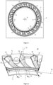
figure 1 est une vue dans un plan radial d'un injecteur selon l'invention. - La
figure 2 est une vue partielle, en perspective des canaux d'un injecteur selon l'invention. - La
figure 3 est une vue partielle, dans un plan radial, des canaux d'un injecteur selon l'invention. - La
figure 4 est une vue partielle, en coupe, dans un plan longitudinal de canaux d'un injecteur selon l'invention. - La
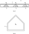
figure 5 est une vue partielle, dans un plan longitudinal, d'ouvertures d'entrée de canaux d'un injecteur selon l'invention. - La
figure 6 est une représentation schématique de la forme d'une section d'entrée d'un canal d'un injecteur selon l'invention. - Sur l'ensemble des figures, les éléments similaires portent des références identiques.
- Selon un premier aspect, l'invention concerne un injecteur pour une turbine haute pression comprenant une couronne 10 annulaire s'étendant autour d'un axe longitudinal A et présentant une bordure extérieure 12 et une bordure intérieure 14.
- Il est précisé que dans le présent document on définit comme axe longitudinal A un axe sensiblement colinéaire ou du moins parallèle à l'axe de rotation de la turbomachine, et on définit comme axe radial C un axe sensiblement perpendiculaire à l'axe longitudinal A (et donc à l'axe de rotation de la turbomachine).
- L'axe longitudinal A est l'axe de révolution de la couronne 10. Ainsi, en partant de l'axe longitudinal A, selon une direction radiale, on rencontrera tout d'abord la bordure intérieure 14 qui est sensiblement annulaire, puis on rencontrera la bordure extérieure 12 qui est sensiblement annulaire.
- La couronne 10 présente une pluralité de canaux 20 destinés à relier un circuit d'air provenant d'une chambre de combustion aux circuits de refroidissement et d'étanchéité d'une turbine.
- Selon une disposition particulièrement avantageuse, chaque canal 20 s'étend dans le plan P de la couronne 10. Il est précisé que le plan P de la couronne est normal à l'axe longitudinal A. Chaque canal 20 présente une ouverture d'entré 22 à proximité de la bordure extérieure 12 et une ouverture de sortie 24 à proximité de la bordure intérieure 14.
- En outre, la couronne 10 présente une série de perçages longitudinaux 18 (i.e. parallèles à l'axe longitudinal A et perpendiculaire au plan P). Les perçages longitudinaux 18 permettent de visser ou riveter la couronne 10 dans une turbomachine.
- D'une manière particulièrement avantageuse, chaque canal 20 présente une variation progressive de son orientation selon une composante tangentielle entre la section d'entrée Φ22 de l'ouverture d'entrée 22 et la section de sortie Φ24 de l'ouverture de sortie 24. Préférentiellement, la variation progressive d'orientation est monotone. Plus précisément, par variation progressive d'orientation, il est entendu, une variation de l'orientation d'un vecteur normal au centre d'une section du canal 20 et ayant pour origine le centre de ladite section.
- D'une manière préférentielle, la section de sortie Φ24 est orientée selon une direction non radiale. Préférentiellement, la section de sortie Φ24 est orientée selon une direction présentant une composante tangentielle B par rapport à l'axe longitudinal A. Il est précisé que par composante tangentielle, on entend une composante (i.e. une direction) appartenant au plan P de la couronne 10 et sensiblement tangente à la bordure intérieure 14. Il est précisé que dans le présent document, l'orientation d'une section s'évalue vis-à-vis de l'orientation d'un vecteur qui a pour origine le centre de ladite section et qui est normal à ladite section.
- En outre, d'une manière particulièrement avantageuse, la section d'entrée Φ22 est orientée selon une direction présentant une composante sensiblement radiale C par rapport à l'axe longitudinal A. Il est précisé que par sensiblement radiale, il est entendu que la composante C peut être inclinée d'une vingtaine de degrés par rapport à un axe radial strictement perpendiculaire à l'axe longitudinal A et appartenant au plan radial P.
- En d'autres termes, selon ces dispositions les canaux sont coudés avec une section d'entrée Φ22 orientée selon une composante radiale C et une section de sortie Φ24 orientée selon une composante tangentielle B. Tel que cela sera détaillé ci-après, cette courbure et l'orientation de la section de sortie Φ22 sont des dispositions particulièrement avantageuses de l'invention.
- De plus, selon une autre disposition avantageuse, chaque section de sortie Φ24 de chaque canal est géométriquement différente de la section d'entrée Φ22 correspondante. Chaque section d'entrée Φ22 présente une aire supérieure à l'aire de la section de sortie Φ24 correspondante. Selon une disposition préférentielle, on cherchera à avoir le rapport « aire de la section d'entrée Φ22 sur aire de la section de sortie Φ24 » le plus élevé possible.
- Néanmoins, ce rapport est limité par les contraintes d'intégration dans une turbomachine. Aussi, dans le cadre d'une intégration dans une turbomachine telle que fabriquée par la demanderesse, on privilégiera un rapport compris entre 1 et 10.
- Tel que cela sera détaillé ultérieurement, la synergie de la variation de l'orientation du canal 20, selon une composante tangentielle, permet d'assurer une accélération régulière et la mise en giration d'un écoulement de gaz dans le canal 20. En d'autres termes, cette disposition permet d'imprimer une vitesse tangentielle à l'air de refroidissement, ce qui, en fonctionnement permet limiter l'échauffement d'un disque de rotor de turbine situé en regard de l'injecteur.
- Typiquement, chaque section d'entrée Φ22 peut présenter la forme d'un parallélogramme surmonté d'un triangle, tel que représenté sur la
figure 6 . Selon une autre disposition chaque section d'entrée Φ22 peut présenter la forme d'un triangle. D'une manière générale, la forme en triangle peut présenter des arêtes arrondies. En d'autres termes, les arêtes de la forme en triangle peuvent être des congés. - En outre, la section de sortie Φ24 peut présenter une forme en parallélogramme. Préférentiellement la section de sortie Φ24 peut présenter une forme en rectangle avec des parois bombées (convexes).
- Ainsi, selon un mode de réalisation préférentiel, la section évolue d'une forme en rectangle surmonté d'un triangle vers une forme en rectangle avec des parois bombées (convexes)
- Selon une disposition particulière, une enveloppe de chaque canal 20 varie d'une forme de la section d'entrée Φ22 à une forme de la section de sortie Φ24.
- Préférentiellement, l'enveloppe de chaque canal 20 présente une paroi d'épaisseur constante. Néanmoins, selon un autre mode de réalisation, l'enveloppe de chaque canal 20 peut présenter une paroi d'épaisseur variable.
- Selon une disposition particulière, Chaque canal 20 peut présenter une longueur pouvant aller de 10 à 100 millimètres.
- En fonctionnement, un flux de gaz pénètre dans l'ouverture d'entrée de chaque canal 20.
- La variation de section et la courbure de chaque canal 20 permet d'accélérer le flux de gaz qui s'échappe par l'ouverture de sortie 24 de chaque canal 20. Cette disposition permet de maximiser la vitesse tangentielle de l'air en sortie de l'injecteur. La maximisation de la vitesse tangentielle de l'air en sortie d'injecteur est une disposition particulièrement avantageuse de l'invention car Elle permet de limiter l'échauffements de la roue mobile située en regard des injecteurs. Plus la vitesse tangentielle de l'air en sortie d'injecteur est élevée, plus le refroidissement de la roue mobile est efficace. De préférence, la vitesse tangentielle de l'air issu des injecteurs est sensiblement égale à la vitesse tangentielle de la roue mobile au rayon où l'air des injecteurs parvient sur la roue mobile située en regard.
- D'une manière particulièrement avantageuse, l'orientation tangentielle de l'ouverture de sortie 24 de chaque canal 20 permet d'avoir un flux tangentiel.
- En outre, il est remarquable que préférentiellement, les canaux 20 sont agencés de sorte que la section d'entrée Φ22 de chaque canal soit orientée sensiblement perpendiculairement à une veine principale d'écoulement de l'air dans le canal.
- Plus précisément, pour apprécier pleinement l'effet de l'injecteur, on peut se baser sur le coefficient d'entrainement (Ke) qui correspond au rapport Vti/Vtm avec Vti la vitesse tangentielle des gaz en sortie des injecteurs et Vtm la vitesse tangentielle de la roue mobile au rayon considéré. L'injecteur selon l'invention permet l'obtention d'un Ke relativement élevé par rapport au injecteurs connus. Typiquement, l'injecteur selon l'invention permet d'obtenir un Ke compris entre 1 et 1.5.
- Ainsi, l'invention propose un injecteur fournissant un certain débit et qui accélère la vitesse des gaz qui les traversent de sorte à ce que la vitesse tangentielle des gaz en sortie des canaux 20 soit sensiblement égale à la vitesse tangentielle d'une roue mobile située en regard en fonctionnement. Cela permet de refroidir efficacement la roue mobile. Grâce à l'injection d'un flux de refroidissement avec une vitesse ayant une importante composante tangentielle.
- En d'autres termes, pour un débit cible donné, l'injecteur selon l'invention permet de fournir une vitesse tangentielle importante grâce à des canaux 20, plus compactes, plus facilement fabricables et plus légers que les canaux des injecteurs connus.
- Selon un autre aspect, l'invention concerne un procédé de fabrication additive de l'injecteur.
- D'une manière connue le procédé de fabrication additive peut comprendre la superposition de couches de poudre fondues par une source d'énergie telle qu'un laser ou un canon à électrons.
- Selon un autre aspect, l'invention concerne une turbomachine intégrant un injecteur selon l'invention.
- Selon un autre aspect, l'invention concerne un aéronef intégrant au moins une turbomachine comprenant l'injecteur selon l'invention.
Claims (9)
- Injecteur de turbine comprenant une couronne (10) annulaire s'étendant autour d'un axe longitudinal (A) et présentant une bordure radialement extérieure (12) et une bordure radialement intérieure (14), la couronne (10) présentant une pluralité de canaux (20) destinés à relier fluidiquement la bordure radialement extérieure (12) à la bordure radialement intérieure (14),
chaque canal (20) s'étendant dans un plan radial (P) de la couronne (10) et présentant une ouverture d'entrée (22) à proximité de la bordure extérieure (12) et une ouverture de sortie (24) à proximité de la bordure radialement intérieure (14), chaque canal (20) présentant une variation progressive de son orientation selon une composante tangentielle entre la section d'entrée (Φ22) de l'ouverture d'entrée (22) et la section de sortie (Φ24) de l'ouverture de sortie (24), caractérisé en ce qu'il est obtenu par fabrication additive et en ce que chaque section d'entrée (Φ22) présente la forme d'un parallélogramme surmonté d'un triangle, ou la forme d'un triangle. - Injecteur selon la revendication 1 dans lequel chaque canal (20) présente une section de sortie (Φ24) orientée tangentiellement.
- Injecteur selon l'une quelconque des revendications 1 ou 2, dans lequel, pour chaque canal (20), la variation de l'orientation est monotone entre la section d'entrée (Φ22) et la section de sortie (Φ24).
- Injecteur selon l'une quelconque des revendication 1 à 3, dans lequel, pour chaque canal (20), la section de sortie (Φ24) du canal (20) est géométriquement différente de la section d'entrée (Φ22) du canal (20) et/ou présente une aire inférieure à l'aire de la section d'entrée (Φ22) du canal (20).
- Injecteur selon l'une quelconque des revendications précédentes, dans lequel chaque section d'entrée (Φ22) présente des arêtes arrondies.
- Injecteur selon la revendication 4, dans lequel chaque section de sortie (Φ24) présente une forme en parallélogramme.
- Injecteur selon la revendication 6, dans lequel chaque section de sortie (Φ24) présente une forme de rectangle.
- Injecteur selon l'une quelconque des revendications 1 à 7, dans lequel chaque canal (20) présente une paroi d'épaisseur constante.
- Turbomachine comprenant au moins un injecteur selon l'une quelconque des revendications 1 à 8.
Applications Claiming Priority (2)
| Application Number | Priority Date | Filing Date | Title |
|---|---|---|---|
| FR1911138A FR3101670B1 (fr) | 2019-10-08 | 2019-10-08 | Injecteur pour une turbine haute pression |
| PCT/FR2020/051769 WO2021069838A1 (fr) | 2019-10-08 | 2020-10-08 | Injecteur pour une turbine haute pression |
Publications (2)
| Publication Number | Publication Date |
|---|---|
| EP4041992A1 EP4041992A1 (fr) | 2022-08-17 |
| EP4041992B1 true EP4041992B1 (fr) | 2025-07-02 |
Family
ID=69173013
Family Applications (1)
| Application Number | Title | Priority Date | Filing Date |
|---|---|---|---|
| EP20793763.2A Active EP4041992B1 (fr) | 2019-10-08 | 2020-10-08 | Injecteur pour une turbine haute pression |
Country Status (5)
| Country | Link |
|---|---|
| US (1) | US11913350B2 (fr) |
| EP (1) | EP4041992B1 (fr) |
| CN (1) | CN114514360B (fr) |
| FR (1) | FR3101670B1 (fr) |
| WO (1) | WO2021069838A1 (fr) |
Families Citing this family (1)
| Publication number | Priority date | Publication date | Assignee | Title |
|---|---|---|---|---|
| FR3127521B1 (fr) * | 2021-09-24 | 2023-12-15 | Safran Aircraft Engines | Carter d’injection d’air de refroidissement pour turbine de turbomachine |
Family Cites Families (21)
| Publication number | Priority date | Publication date | Assignee | Title |
|---|---|---|---|---|
| US6276896B1 (en) * | 2000-07-25 | 2001-08-21 | Joseph C. Burge | Apparatus and method for cooling Axi-Centrifugal impeller |
| FR2841591B1 (fr) | 2002-06-27 | 2006-01-13 | Snecma Moteurs | Circuits de ventilation de la turbine d'une turbomachine |
| US20070271930A1 (en) * | 2006-05-03 | 2007-11-29 | Mitsubishi Heavy Industries, Ltd. | Gas turbine having cooling-air transfer system |
| FR2937371B1 (fr) | 2008-10-20 | 2010-12-10 | Snecma | Ventilation d'une turbine haute-pression dans une turbomachine |
| FR2949518B1 (fr) * | 2009-08-31 | 2011-10-21 | Snecma | Compresseur de turbomachine ayant des injecteurs d'air |
| US8677766B2 (en) * | 2010-04-12 | 2014-03-25 | Siemens Energy, Inc. | Radial pre-swirl assembly and cooling fluid metering structure for a gas turbine engine |
| US8636470B2 (en) * | 2010-10-13 | 2014-01-28 | Honeywell International Inc. | Turbine blades and turbine rotor assemblies |
| EP2557269A1 (fr) * | 2011-08-08 | 2013-02-13 | Siemens Aktiengesellschaft | Refroidissement par film de composants de turbine |
| CH705840A1 (de) * | 2011-12-06 | 2013-06-14 | Alstom Technology Ltd | Hochdruck-Verdichter, insbesondere in einer Gasturbine. |
| US9133722B2 (en) * | 2012-04-30 | 2015-09-15 | General Electric Company | Transition duct with late injection in turbine system |
| US9435206B2 (en) * | 2012-09-11 | 2016-09-06 | General Electric Company | Flow inducer for a gas turbine system |
| FR3009339B1 (fr) * | 2013-07-30 | 2018-01-26 | Safran Aircraft Engines | Turbomachine comprenant un dispositif de refroidissement du pylone |
| US9988935B2 (en) * | 2014-07-31 | 2018-06-05 | United Technologies Corporation | Gas turbine engine with axial compressor with internal cooling pathways |
| JP6484430B2 (ja) * | 2014-11-12 | 2019-03-13 | 三菱重工業株式会社 | タービンの冷却構造及びガスタービン |
| DE102015111750A1 (de) * | 2015-07-20 | 2017-01-26 | Rolls-Royce Deutschland Ltd & Co Kg | Gekühltes Turbinenlaufrad für ein Flugtriebwerk |
| US10683805B2 (en) * | 2015-07-30 | 2020-06-16 | Safran Aircraft Engines | Anti-icing system for a turbine engine vane |
| ITUB20153103A1 (it) * | 2015-08-13 | 2017-02-13 | Ansaldo Energia Spa | Gruppo turbina a gas con pre-vorticatore adattativo |
| US20170292393A1 (en) * | 2016-04-08 | 2017-10-12 | United Technologies Corporation | Tangential on-board injectors for gas turbine engines |
| US20190323354A1 (en) * | 2016-11-25 | 2019-10-24 | Societe De Commercialisation Des Produits De La Recherche Appliquee Socpra Sciences Et Genie S.E.C. | High temperature ceramic rotary turbomachinery |
| US11021962B2 (en) * | 2018-08-22 | 2021-06-01 | Raytheon Technologies Corporation | Turbulent air reducer for a gas turbine engine |
| CN109798153B (zh) * | 2019-03-28 | 2023-08-22 | 中国船舶重工集团公司第七0三研究所 | 一种应用于船用燃气轮机涡轮轮盘的冷却结构 |
-
2019
- 2019-10-08 FR FR1911138A patent/FR3101670B1/fr active Active
-
2020
- 2020-10-08 WO PCT/FR2020/051769 patent/WO2021069838A1/fr not_active Ceased
- 2020-10-08 US US17/767,314 patent/US11913350B2/en active Active
- 2020-10-08 EP EP20793763.2A patent/EP4041992B1/fr active Active
- 2020-10-08 CN CN202080070506.3A patent/CN114514360B/zh active Active
Also Published As
| Publication number | Publication date |
|---|---|
| WO2021069838A1 (fr) | 2021-04-15 |
| US11913350B2 (en) | 2024-02-27 |
| EP4041992A1 (fr) | 2022-08-17 |
| CN114514360A (zh) | 2022-05-17 |
| CN114514360B (zh) | 2024-09-17 |
| US20220364470A1 (en) | 2022-11-17 |
| FR3101670B1 (fr) | 2021-10-08 |
| FR3101670A1 (fr) | 2021-04-09 |
Similar Documents
| Publication | Publication Date | Title |
|---|---|---|
| EP2821597B1 (fr) | Bec de séparation avec tôle formant une surface de guidage du flux et un canal de dégivrage | |
| EP2740905B1 (fr) | Bec de séparation d'une turbomachine axiale, compresseur et turbomachine axiale associés | |
| CA2764408C (fr) | Turbomachine comprenant des moyens ameliores de reglage du debit d'un flux d'air de refroidissement preleve en sortie de compresseur haute pression | |
| EP4405569B1 (fr) | Carter d'injection d'air de refroidissement pour turbine de turbomachine | |
| EP1911936B1 (fr) | Canal de transition entre deux étages de turbine | |
| FR2732405A1 (fr) | Dispositif pour refroidir le rotor d'une turbine a gaz | |
| EP3130765A1 (fr) | Bec de separation degivrant de compresseur de turbomachine axiale | |
| EP4041992B1 (fr) | Injecteur pour une turbine haute pression | |
| EP2078822B1 (fr) | Moteur à turbine à gaz avec clapet de mise en communication de deux enceintes | |
| FR3036140B1 (fr) | Turbomachine d'aeronef a effet coanda | |
| FR2999249A1 (fr) | Compresseur pour turbomachine dote de moyens de refroidissement d'un joint tournant assurant l'etancheite entre un redresseur et un rotor | |
| WO2020193913A1 (fr) | Aube de turbomachine equipee d'un circuit de refroidissement optimise | |
| WO2009153480A2 (fr) | Turbomachine avec diffuseur | |
| EP4034755A1 (fr) | Dispositif de refroidissement par jets d'air d'un carter de turbine | |
| WO2020254764A1 (fr) | Procédé de revêtement d'une aube de redresseur de turbomachine, aube de redresseur associée | |
| FR3108938A1 (fr) | Anneau d’étanchéité pour un rotor de turbine de turbomachine | |
| FR3092865A1 (fr) | Disque de rotor avec arret axial des aubes, ensemble d’un disque et d’un anneau et turbomachine | |
| EP3847339B1 (fr) | Disque de rotor avec arret axial des aubes, ensemble d'un disque et d'un anneau et turbomachine | |
| FR3108661A1 (fr) | Couronne d’injecteurs de turbine | |
| WO2026052915A1 (fr) | Module pour une turbomachine d'aeronef | |
| WO2025037058A1 (fr) | Joint d'étanchéité pour turbomachine | |
| EP4684102A1 (fr) | Architecture pour joint d'etancheite de turbomachine | |
| FR3160725A1 (fr) | Ensemble statorique de turbine de turbomachine d’aeronef, presentant un flux d’air de purge statorique a efficacite renforcee | |
| FR3166164A1 (fr) | Module pour une turbomachine d’aeronef | |
| FR3165038A1 (fr) | Systeme de lubrification pour une turbomachine d’aeronef |
Legal Events
| Date | Code | Title | Description |
|---|---|---|---|
| STAA | Information on the status of an ep patent application or granted ep patent |
Free format text: STATUS: UNKNOWN |
|
| STAA | Information on the status of an ep patent application or granted ep patent |
Free format text: STATUS: THE INTERNATIONAL PUBLICATION HAS BEEN MADE |
|
| PUAI | Public reference made under article 153(3) epc to a published international application that has entered the european phase |
Free format text: ORIGINAL CODE: 0009012 |
|
| STAA | Information on the status of an ep patent application or granted ep patent |
Free format text: STATUS: REQUEST FOR EXAMINATION WAS MADE |
|
| 17P | Request for examination filed |
Effective date: 20220504 |
|
| AK | Designated contracting states |
Kind code of ref document: A1 Designated state(s): AL AT BE BG CH CY CZ DE DK EE ES FI FR GB GR HR HU IE IS IT LI LT LU LV MC MK MT NL NO PL PT RO RS SE SI SK SM TR |
|
| DAV | Request for validation of the european patent (deleted) | ||
| DAX | Request for extension of the european patent (deleted) | ||
| RIC1 | Information provided on ipc code assigned before grant |
Ipc: F02C 7/18 20060101ALN20240527BHEP Ipc: B33Y 80/00 20150101ALI20240527BHEP Ipc: B22F 10/28 20210101ALI20240527BHEP Ipc: B22F 5/00 20060101ALI20240527BHEP Ipc: F01D 5/08 20060101AFI20240527BHEP |
|
| RIC1 | Information provided on ipc code assigned before grant |
Ipc: F02C 7/18 20060101ALN20241114BHEP Ipc: B33Y 80/00 20150101ALI20241114BHEP Ipc: B22F 10/28 20210101ALI20241114BHEP Ipc: B22F 5/00 20060101ALI20241114BHEP Ipc: F01D 5/08 20060101AFI20241114BHEP |
|
| GRAP | Despatch of communication of intention to grant a patent |
Free format text: ORIGINAL CODE: EPIDOSNIGR1 |
|
| STAA | Information on the status of an ep patent application or granted ep patent |
Free format text: STATUS: GRANT OF PATENT IS INTENDED |
|
| INTG | Intention to grant announced |
Effective date: 20250220 |
|
| GRAS | Grant fee paid |
Free format text: ORIGINAL CODE: EPIDOSNIGR3 |
|
| GRAA | (expected) grant |
Free format text: ORIGINAL CODE: 0009210 |
|
| STAA | Information on the status of an ep patent application or granted ep patent |
Free format text: STATUS: THE PATENT HAS BEEN GRANTED |
|
| AK | Designated contracting states |
Kind code of ref document: B1 Designated state(s): AL AT BE BG CH CY CZ DE DK EE ES FI FR GB GR HR HU IE IS IT LI LT LU LV MC MK MT NL NO PL PT RO RS SE SI SK SM TR |
|
| REG | Reference to a national code |
Ref country code: GB Ref legal event code: FG4D Free format text: NOT ENGLISH |
|
| REG | Reference to a national code |
Ref country code: CH Ref legal event code: EP |
|
| REG | Reference to a national code |
Ref country code: DE Ref legal event code: R096 Ref document number: 602020053880 Country of ref document: DE |
|
| REG | Reference to a national code |
Ref country code: IE Ref legal event code: FG4D Free format text: LANGUAGE OF EP DOCUMENT: FRENCH |
|
| REG | Reference to a national code |
Ref country code: NL Ref legal event code: MP Effective date: 20250702 |
|
| PG25 | Lapsed in a contracting state [announced via postgrant information from national office to epo] |
Ref country code: PT Free format text: LAPSE BECAUSE OF FAILURE TO SUBMIT A TRANSLATION OF THE DESCRIPTION OR TO PAY THE FEE WITHIN THE PRESCRIBED TIME-LIMIT Effective date: 20251103 |
|
| PG25 | Lapsed in a contracting state [announced via postgrant information from national office to epo] |
Ref country code: NL Free format text: LAPSE BECAUSE OF FAILURE TO SUBMIT A TRANSLATION OF THE DESCRIPTION OR TO PAY THE FEE WITHIN THE PRESCRIBED TIME-LIMIT Effective date: 20250702 |
|
| REG | Reference to a national code |
Ref country code: AT Ref legal event code: MK05 Ref document number: 1809444 Country of ref document: AT Kind code of ref document: T Effective date: 20250702 |
|
| PG25 | Lapsed in a contracting state [announced via postgrant information from national office to epo] |
Ref country code: IS Free format text: LAPSE BECAUSE OF FAILURE TO SUBMIT A TRANSLATION OF THE DESCRIPTION OR TO PAY THE FEE WITHIN THE PRESCRIBED TIME-LIMIT Effective date: 20251102 |
|
| PGFP | Annual fee paid to national office [announced via postgrant information from national office to epo] |
Ref country code: DE Payment date: 20251020 Year of fee payment: 6 |
|
| PGFP | Annual fee paid to national office [announced via postgrant information from national office to epo] |
Ref country code: GB Payment date: 20251029 Year of fee payment: 6 |
|
| PG25 | Lapsed in a contracting state [announced via postgrant information from national office to epo] |
Ref country code: NO Free format text: LAPSE BECAUSE OF FAILURE TO SUBMIT A TRANSLATION OF THE DESCRIPTION OR TO PAY THE FEE WITHIN THE PRESCRIBED TIME-LIMIT Effective date: 20251002 |
|
| REG | Reference to a national code |
Ref country code: LT Ref legal event code: MG9D |
|
| PG25 | Lapsed in a contracting state [announced via postgrant information from national office to epo] |
Ref country code: AT Free format text: LAPSE BECAUSE OF FAILURE TO SUBMIT A TRANSLATION OF THE DESCRIPTION OR TO PAY THE FEE WITHIN THE PRESCRIBED TIME-LIMIT Effective date: 20250702 |
|
| PG25 | Lapsed in a contracting state [announced via postgrant information from national office to epo] |
Ref country code: FI Free format text: LAPSE BECAUSE OF FAILURE TO SUBMIT A TRANSLATION OF THE DESCRIPTION OR TO PAY THE FEE WITHIN THE PRESCRIBED TIME-LIMIT Effective date: 20250702 |
|
| PG25 | Lapsed in a contracting state [announced via postgrant information from national office to epo] |
Ref country code: HR Free format text: LAPSE BECAUSE OF FAILURE TO SUBMIT A TRANSLATION OF THE DESCRIPTION OR TO PAY THE FEE WITHIN THE PRESCRIBED TIME-LIMIT Effective date: 20250702 |
|
| PGFP | Annual fee paid to national office [announced via postgrant information from national office to epo] |
Ref country code: FR Payment date: 20251023 Year of fee payment: 6 |
|
| PG25 | Lapsed in a contracting state [announced via postgrant information from national office to epo] |
Ref country code: GR Free format text: LAPSE BECAUSE OF FAILURE TO SUBMIT A TRANSLATION OF THE DESCRIPTION OR TO PAY THE FEE WITHIN THE PRESCRIBED TIME-LIMIT Effective date: 20251003 |
|
| PG25 | Lapsed in a contracting state [announced via postgrant information from national office to epo] |
Ref country code: SE Free format text: LAPSE BECAUSE OF FAILURE TO SUBMIT A TRANSLATION OF THE DESCRIPTION OR TO PAY THE FEE WITHIN THE PRESCRIBED TIME-LIMIT Effective date: 20250702 Ref country code: CZ Free format text: LAPSE BECAUSE OF FAILURE TO SUBMIT A TRANSLATION OF THE DESCRIPTION OR TO PAY THE FEE WITHIN THE PRESCRIBED TIME-LIMIT Effective date: 20250702 |
|
| PG25 | Lapsed in a contracting state [announced via postgrant information from national office to epo] |
Ref country code: LV Free format text: LAPSE BECAUSE OF FAILURE TO SUBMIT A TRANSLATION OF THE DESCRIPTION OR TO PAY THE FEE WITHIN THE PRESCRIBED TIME-LIMIT Effective date: 20250702 |
|
| PG25 | Lapsed in a contracting state [announced via postgrant information from national office to epo] |
Ref country code: PL Free format text: LAPSE BECAUSE OF FAILURE TO SUBMIT A TRANSLATION OF THE DESCRIPTION OR TO PAY THE FEE WITHIN THE PRESCRIBED TIME-LIMIT Effective date: 20250702 Ref country code: BG Free format text: LAPSE BECAUSE OF FAILURE TO SUBMIT A TRANSLATION OF THE DESCRIPTION OR TO PAY THE FEE WITHIN THE PRESCRIBED TIME-LIMIT Effective date: 20250702 |
|
| PG25 | Lapsed in a contracting state [announced via postgrant information from national office to epo] |
Ref country code: RS Free format text: LAPSE BECAUSE OF FAILURE TO SUBMIT A TRANSLATION OF THE DESCRIPTION OR TO PAY THE FEE WITHIN THE PRESCRIBED TIME-LIMIT Effective date: 20251002 |
|
| PG25 | Lapsed in a contracting state [announced via postgrant information from national office to epo] |
Ref country code: ES Free format text: LAPSE BECAUSE OF FAILURE TO SUBMIT A TRANSLATION OF THE DESCRIPTION OR TO PAY THE FEE WITHIN THE PRESCRIBED TIME-LIMIT Effective date: 20250702 |
|
| PG25 | Lapsed in a contracting state [announced via postgrant information from national office to epo] |
Ref country code: RO Free format text: LAPSE BECAUSE OF FAILURE TO SUBMIT A TRANSLATION OF THE DESCRIPTION OR TO PAY THE FEE WITHIN THE PRESCRIBED TIME-LIMIT Effective date: 20250702 |
|
| PG25 | Lapsed in a contracting state [announced via postgrant information from national office to epo] |
Ref country code: SM Free format text: LAPSE BECAUSE OF FAILURE TO SUBMIT A TRANSLATION OF THE DESCRIPTION OR TO PAY THE FEE WITHIN THE PRESCRIBED TIME-LIMIT Effective date: 20250702 |
|
| PG25 | Lapsed in a contracting state [announced via postgrant information from national office to epo] |
Ref country code: DK Free format text: LAPSE BECAUSE OF FAILURE TO SUBMIT A TRANSLATION OF THE DESCRIPTION OR TO PAY THE FEE WITHIN THE PRESCRIBED TIME-LIMIT Effective date: 20250702 |
|
| PG25 | Lapsed in a contracting state [announced via postgrant information from national office to epo] |
Ref country code: IT Free format text: LAPSE BECAUSE OF FAILURE TO SUBMIT A TRANSLATION OF THE DESCRIPTION OR TO PAY THE FEE WITHIN THE PRESCRIBED TIME-LIMIT Effective date: 20250702 |
|
| PG25 | Lapsed in a contracting state [announced via postgrant information from national office to epo] |
Ref country code: EE Free format text: LAPSE BECAUSE OF FAILURE TO SUBMIT A TRANSLATION OF THE DESCRIPTION OR TO PAY THE FEE WITHIN THE PRESCRIBED TIME-LIMIT Effective date: 20250702 Ref country code: SK Free format text: LAPSE BECAUSE OF FAILURE TO SUBMIT A TRANSLATION OF THE DESCRIPTION OR TO PAY THE FEE WITHIN THE PRESCRIBED TIME-LIMIT Effective date: 20250702 |