EP4041497B1 - Inserting gun with exchange valve - Google Patents
Inserting gun with exchange valve Download PDFInfo
- Publication number
- EP4041497B1 EP4041497B1 EP20793151.0A EP20793151A EP4041497B1 EP 4041497 B1 EP4041497 B1 EP 4041497B1 EP 20793151 A EP20793151 A EP 20793151A EP 4041497 B1 EP4041497 B1 EP 4041497B1
- Authority
- EP
- European Patent Office
- Prior art keywords
- pneumatic
- conduit
- air
- valve
- exchange
- Prior art date
- Legal status (The legal status is an assumption and is not a legal conclusion. Google has not performed a legal analysis and makes no representation as to the accuracy of the status listed.)
- Active
Links
Images




Classifications
-
- B—PERFORMING OPERATIONS; TRANSPORTING
- B25—HAND TOOLS; PORTABLE POWER-DRIVEN TOOLS; MANIPULATORS
- B25B—TOOLS OR BENCH DEVICES NOT OTHERWISE PROVIDED FOR, FOR FASTENING, CONNECTING, DISENGAGING, OR HOLDING
- B25B27/00—Hand tools, specially adapted for fitting together or separating parts or objects whether or not involving some deformation, not otherwise provided for
- B25B27/0007—Tools for fixing internally screw-threaded tubular fasteners
- B25B27/0014—Tools for fixing internally screw-threaded tubular fasteners motor-driven
Definitions
- the present invention relates to a pneumohydraulic inserting gun.
- the present invention falls in the technical field of inserting guns suitable to perform an action on a respective deformable threaded insert to be riveted, to lock it on one or more specific components, mutually locking them.
- inserting guns are known, in a very general manner, as “riveters” and the deformable threaded inserts to be riveted are known, in a very general manner, as “rivets”.
- the term “rivet” will refer to the deformable threaded insert to be riveted, while since it is the subject of the present invention, the term inserting gun or pneumohydraulic inserting gun will always refer to the gun.
- the known inserting guns perform a series of actions on the rivet, by means of which the locking is obtained. Indeed, in a first moment, the inserter performs an action in which the rivet is housed in a housing, e.g. a hole, consisting of the coupling of two components, and is brought, with the head thereof, to abut on a wall of a first component; in a second moment, the inserter performs an action which plastically deforms the rivet so as to obtain the fastening of the threaded insert and/or the mutual fastening of the components.
- a housing e.g. a hole, consisting of the coupling of two components
- the present invention specifically relates to servo-assisted inserting guns.
- a known embodiment of inserting gun is that described in document EP2150378A2 which discloses the preamble of claim 1 to the same Applicant.
- the inserting gun of the present invention forms part of that group of inserting guns in which engagement and disengagement actions on the rivet are provided by screwing and unscrewing.
- the inserting gun of the present invention aims at having improved features with respect to the features of the known inserting guns, with particular reference to the features of the inserting gun described in document EP2150378 . Indeed, the inserting gun of the present invention is more efficient than the known solutions, for example being faster when moving the respective components and having smaller volumes.
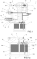
- Reference numeral 1 in the accompanying drawings indicates an inserting gun according to the present invention. As extensively shown hereinafter, the inserting gun 1 is of the pneumohydraulic type.
- Rivet 500 is a commercial component, comprising a threaded hole 550, a yielding portion 551 suitable to be plastically modified, as well as a head 552 suitable to abut on a wall of a component.
- reference numeral 551' indicates the collar obtained through the plastic modification to which said yielding portion 551 is subjected, by means of specific operations of the inserting gun 1.
- the inserting gun 1 comprises a threaded tie rod 2.
- a threaded tie rod 2 extends along a working axis X-X and is suitable for engaging rivet 500.
- the threaded tie rod 2 preferably engages rivet 500 in the threaded axial hole 550 thereof.
- the threaded tie rod 2 is suitable for moving rivet 500 both rotationally and axially with respect to said working axis X-X.
- the threaded tie rod 2 has the shape, e.g. outline, such as to allow said interaction with the respective rivet 500.
- rivet 500 is preferably pushed and moved along axis X-X.
- the inserting gun 1 comprises a motor 3 operatively connected to the threaded tie rod 2 to command it in rotation clockwise or counterclockwise direction.
- the rotation of the threaded tie rod 2 corresponds to the engagement or disengagement of rivet 500.
- the clockwise rotation (or, towards the right) of the threaded tie rod 2 preferably corresponds to the screwing of the threaded tie rod 2 to rivet 500; vice versa, the counterclockwise rotation (or, towards the left) of the threaded tie rod 2 corresponds to the unscrewing of the threaded tie rod 2 to rivet 500.
- motor 3 is of a pneumatic type.
- Motor 3 is preferably positioned at the working axis X-X at an end of the threaded tie rod 2 opposite to the end suitable to engage rivet 500.
- the inserting gun 1 comprises an oleodynamic system 4 suitable to move the threaded tie rod 2 and motor 3 along the working axis X-X.
- Rivet 500 previously engaged with the threaded tie rod 2 (by screwing), is plastically deformed by means of such a movement along axis X-X, in particular in the yielding portion 551 thereof, to be fastened and fasten the respective components.
- a thrust fluid F flows in the oleodynamic system 4.
- Said thrust fluid F preferably is a viscose fluid, e.g. an oil.
- two oil chambers fluidically connected to each other, in which there is thrust fluid, i.e. oil, are housed in the inserting gun 1; in which one of said chambers at least partially houses the threaded tie rod 2 and motor 3.
- the inserting gun 1 also comprises a pneumatic amplifier group 5 suitable to perform a compression action on the thrust fluid F, amplifying the thrust action thereof. Therefore, the pneumatic amplifier group 5 preferably is such as to amplify the action of the oleodynamic system 4. In particular, the action of the pneumatic amplifier group 5 is performed in an oil chamber and transmitted to the other oil chamber to be discharged onto threaded tie rod 2 and engine 3.
- the pneumatic amplifier group 5 comprises a pneumatic chamber 50, a piston 51 and a plunger 52.
- piston 51 is entirely housed in the pneumatic chamber 50, while plunger 52 is integrally connected to said piston 51 and is at least partially housed in the pneumatic chamber 50.
- the protruding portion of plunger 52 preferably is the portion which engages the oleodynamic system 4, pushing it onto the thrust fluid F, preferably into the respective oil chamber.
- piston 51 and plunger 52 are axially movable along a thrust axis Y-Y.
- plunger 52 is suitable for performing a compression action on the thrust fluid F, thus amplifying the thrust action thereof.
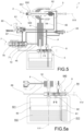
- the inserting gun 1 comprises a pneumatic system 6.
- Said pneumatic system 6 is fed by a source of compressed air.
- Said source of compressed air is preferably provided within the area of use of the inserting gun 1 supplied by a specific pneumatic plant.
- the pneumatic system 6 aims at supplying and managing the supply of pressurized air to the air-fed components of the inserting gun 1, such as, for example, the motor 3 and the pneumatic amplifier group 5.
- the pneumatic system 6 comprises a plurality of fluidic conduits which allow the fluidic connection between the various components, as hereinafter extensively described and extensively shown in the accompanying drawings.
- the pneumatic system 6 indeed comprises a first conduit 64, a second conduit 65, a command conduit 66 and a management conduit 67.
- conduit means both a single fluidic segment in which a specific amount of air flows, and a fluidic passageway consisting of a plurality of branches in which specific amounts of air flow.
- the pneumatic system 6 comprises a trigger 60 which is operable by the user.
- the pneumatic system 6 further comprises an auxiliary valve 62 suitable to allow the supply of motor 3 to rotate it in a first direction of rotation (preferably in clockwise direction).
- Said auxiliary valve 62 is actuated in opening by the threaded tie rod 2.
- the threaded tie rod 2 is pushed, with rivet 500, along the working axis X-X and the auxiliary valve 62 is moved in opening by means of a pressure action of the inserting gun 1, in particular of the threaded tie rod 2.
- the auxiliary valve 62 is connectable to the compressed air source through the first conduit 64.
- the pneumatic system 6 comprises a main valve 61 operatively connected to trigger 60.
- actuating trigger 60 results in opening the main valve 61.
- the main valve 61 is fluidically connected to the first conduit 64 and to the management conduit 67.
- the actuation of trigger 60 and the opening of the main valve 61 results in the fluidic connection of the first conduit 64 with the management conduit 67.
- the inserting gun 1 further comprises a hydropneumatic regulating valve 7.
- the hydropneumatic regulating valve 7 is fluidically connected to the oleodynamic system 4 and to the pneumatic system 6.
- the hydropneumatic regulating valve 7 is fluidically connected to the second conduit 65, to the command conduit 66 and to the management conduit 67.
- the hydropneumatic regulating valve 7 is suitable for receiving the air which flows through the management conduit 67 as the main valve 61 opens.
- the hydropneumatic regulating valve 7 is suitable for commanding the flow of air through the second conduit 65, i.e. towards motor 3, and/or through the command conduit 66, i.e. towards the pneumatic amplifier group 5.
- the hydropneumatic regulating valve 7 comprises first movable members 71 and second movable members 72 which are positionable along a hydropneumatic axis Z-Z in a:
- the passage from the first to the third configuration results in the plastic modification or rivet 500, and the locking thereof.
- the thrust fluid F is suitable for reaching the hydropneumatic valve 7 through an oil conduit 45.
- the pneumatic system 6 further comprises an emergency valve member 63 fluidically connected to the first conduit 64 and to the second conduit 65, suitable to command and regulate the air flow flowing in the first conduit 64 and/or the air flow flowing in the second conduit 65 towards motor 3.
- an emergency valve member 63 fluidically connected to the first conduit 64 and to the second conduit 65, suitable to command and regulate the air flow flowing in the first conduit 64 and/or the air flow flowing in the second conduit 65 towards motor 3.
- said emergency valve member 63 is suitable for commanding and regulating the air flow towards engine 3 so as to command the rotation of the threaded tie rod 2 to unscrew it from rivet 500.
- the unscrewing, by means of the emergency valve member 63 is also performed in circumstances in which the overall working cycle of the inserting gun 1 is not successful and doesn't come to an end.
- the emergency valve member 63 is suitable for keeping active the supply of air to motor 3, even in a configuration in which trigger 60 is unexpectedly released.
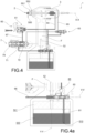
- the inserting gun 1 comprises an exchange valve 8 fluidically connected to the first conduit 64 and to the command conduit 66, and which is configurable in a plurality of configurations in which it regulates the flow or the discharge flowing in said conduits to and from the pneumatic chamber 50.
- the exchange valve 8 extends along an exchange axis V-V.
- the exchange valve 8 is movable with respect to said exchange axis V-V.
- the exchange valve 8 is fluidically positioned between the hydropneumatic regulating valve 7 and the pneumatic amplifier group 5.
- the hydropneumatic regulating valve 7 is fluidically connected to the pneumatic amplifier group 5 through the exchange valve 8.
- the air preferably flows into, or flows out of, the pneumatic amplifier group 5 through the exchange valve 8.
- the exchange valve 8 is positionable along the exchange axis V-V in a first exchange position and in a second exchange position.
- the air flows to the exchange valve 8 through the first conduit 64 or through the command conduit 66 as a function of the positioning of the hydropneumatic regulating valve 7.
- the exchange valve 8 comprises an elastic bias member 80 suitable to keep the exchange valve 8 in the first exchange position.
- the action of pushing the air through the command conduit 66 preferably exceeds the elastic biasing action of the elastic bias member 80 in the second exchange position. In other words, the second exchange position is reached once the action of the elastic bias member 80 has been achieved.
- the elastic bias member 80 preferably is a helical spring.
- the exchange valve 8 is fluidically connected to air discharge openings 84, 85 suitable to allow the discharge of the air of the pneumatic system 6 towards the ambient. As mentioned, indeed the discharge of the air in the air chamber 50 is also managed through the exchange valve 8.
- the already described pneumatic chamber 50 comprises a first pneumatic half-chamber 501 and a second pneumatic half-chamber 502 which are mutually separated by piston 51.
- the exchange valve 8 is fluidically connected to both the first pneumatic half-chamber 501 and the second pneumatic half-chamber 502 so that the supply of air in one half-chamber and the discharge of air in the other half-chamber is commanded as a function of its positioning along the exchange axis V-V.
- the movement of piston 51 and simultaneously of plunger 52 in a first axial direction or in a second axial direction is obtained as a function of which pneumatic half-chamber is filled with air.
- the pneumatic amplifier group 5 has a dual effect. Wth the axial positioning thereof, the exchange valve 8 performs a thrust action on piston 51 in a first direction and in a second direction.
- the exchange valve 8 is fluidically connected to the first pneumatic half-chamber 501 by means of a first command conduit 81 through a first port 810.
- the exchange valve 8 is fluidically connected to the second pneumatic half-chamber 502 by means of a second command conduit 82 through a second port 820.
- the first port 810 and the second port 820 are axially positioned spaced apart along the thrust axis Y-Y.
- the first exchange position of the exchange valve 8 corresponds to the supply of air to the second pneumatic half-chamber 502 by means of a second command conduit 82 through the second port 820, through the first conduit 64.
- the second exchange position of the exchange valve 8 corresponds to the supply of air to the first pneumatic half-chamber 501 by means of the first command conduit 81 through the first port 810, through the command conduit 66.
- the hydropneumatic regulating valve 7 comprises elastic means 79 suitable to carry out an axial action that keeps the first movable members 71 and the second movable members 72 in the first configuration, in which the third configuration is reached by the action of fluid F that passes the elastic means 79.
- the elastic means 79 embedded in the hydropneumatic regulating valve 7 preferably are calibratable so as to regulate the respective elastic action as a function of the action of the thrust fluid F.
- the hydropneumatic regulating valve 7 is in the shape of a cartridge, being insertable and extractable along the hydropneumatic axis Z-Z.
- the exchange valve 8 preferably is in the shape of a cartridge, being insertable and extractable along the exchange axis V-V.
- the inserting gun 1 comprises a gun body 100 and a pneumatic tank body 150 which is mountable to the gun body 100.
- the gun body 100 is grippable by the user and contains the threaded tie rod 2, engine 3, and the oleodynamic system 4.
- the gun body 100 preferably comprises a handle 101 to which the pneumatic tank body 150 is preferably connected.
- Trigger 60 is preferably located at said handle.
- the pneumatic tank body 150 houses the pneumatic amplifier group 5 so that plunger 52 protrudes along the thrust axis Y-Y from said tank group 150 so that it is suitable for finding accommodation in the gun body 100 and thus engaging the oleodynamic system 4.
- the pneumatic tank body 150 comprises a distribution flange 151 which is mountable on the gun body 100 and a barrel body 152 which is mountable to said distribution flange 151; barrel body 152 and distribution flange 151 define said pneumatic chamber 50 in the mutual, preferably sealing, engagement.
- the exchange valve 8 is housed in the distribution flange 151.
- the distribution flange 151 preferably comprises a specifically shaped housing for the exchange valve 8.
- the pneumatic regulating valve 7 is housed in the distribution flange 151.
- the distribution flange 151 preferably comprises a specifically shaped housing for the pneumatic regulating valve 7.
- the emergency valve member 63 is housed in the distribution flange 151.
- the distribution flange 151 preferably comprises a specifically shaped housing for the emergency valve member 156.
- the respective valve or valve member is insertable as a cartridge.
- the aforesaid fluidic connecting conduits between the components therein provided are obtained in the pneumatic tank body 150.
- fluidic conduits are obtained in the pneumatic tank body 150 which put into connection the exchange valve 8 and the thrust amplifier group 5, such as, for example the air discharge openings 84, 85 and the first command conduit 81 and the second command conduit 82.
- such fluidic conduits are preferably made in the distribution flange 151.
- connection with the source of compressed air is preferably performed on the distribution flange 151, through a connection port 640.
- connection port 640 Preferably, there are more than one connection port 640', 640" on the distribution flange 151, for example two on two opposite sides.
- the inserting gun of the present invention fully achieves the preset object by solving the problems raised from the typical solutions of the prior art.
- the inserting gun is quicker and more compact than the known solutions.
- the inserting gun is quicker and more compact than the inserting gun solution known from the teachings of document EP2150378 .
- the operating cycle of the inserting gun has been greatly speeded up, with particular reference to the plastic deforming operations of the rivet and the disengagement of the inserting gun therefrom.
- the pneumatic amplifier group is pneumatically commanded in both directions.
- the pneumatic amplifier group does not need elastic return elements.
Landscapes
- Engineering & Computer Science (AREA)
- Mechanical Engineering (AREA)
- Nozzles (AREA)
- Coating Apparatus (AREA)
- Fuel-Injection Apparatus (AREA)
- Seal Device For Vehicle (AREA)
Priority Applications (1)
| Application Number | Priority Date | Filing Date | Title |
|---|---|---|---|
| HRP20240006TT HRP20240006T1 (hr) | 2019-10-09 | 2020-10-02 | Pištolj za umetanje s ventilom za izmjenu |
Applications Claiming Priority (2)
| Application Number | Priority Date | Filing Date | Title |
|---|---|---|---|
| IT102019000018335A IT201900018335A1 (it) | 2019-10-09 | 2019-10-09 | Pistola insertatrice con valvola di scambio |
| PCT/IB2020/059271 WO2021070025A1 (en) | 2019-10-09 | 2020-10-02 | Inserting gun with exchange valve |
Publications (2)
| Publication Number | Publication Date |
|---|---|
| EP4041497A1 EP4041497A1 (en) | 2022-08-17 |
| EP4041497B1 true EP4041497B1 (en) | 2024-01-03 |
Family
ID=69701315
Family Applications (1)
| Application Number | Title | Priority Date | Filing Date |
|---|---|---|---|
| EP20793151.0A Active EP4041497B1 (en) | 2019-10-09 | 2020-10-02 | Inserting gun with exchange valve |
Country Status (7)
| Country | Link |
|---|---|
| EP (1) | EP4041497B1 (pl) |
| ES (1) | ES2971141T3 (pl) |
| HR (1) | HRP20240006T1 (pl) |
| HU (1) | HUE065009T2 (pl) |
| IT (1) | IT201900018335A1 (pl) |
| PL (1) | PL4041497T3 (pl) |
| WO (1) | WO2021070025A1 (pl) |
Families Citing this family (2)
| Publication number | Priority date | Publication date | Assignee | Title |
|---|---|---|---|---|
| FR3107201B1 (fr) * | 2020-02-13 | 2022-06-10 | Bollhoff Otalu | outil et procédé de sertissage d’un élément sur un support |
| IT202300005091A1 (it) * | 2023-03-17 | 2024-09-17 | Ober S P A | Pistola insertatrice |
Family Cites Families (1)
| Publication number | Priority date | Publication date | Assignee | Title |
|---|---|---|---|---|
| ITBO20070311A1 (it) | 2007-04-27 | 2008-10-28 | Ober S P A | Pistola rivettatrice pneumoidraulica |
-
2019
- 2019-10-09 IT IT102019000018335A patent/IT201900018335A1/it unknown
-
2020
- 2020-10-02 ES ES20793151T patent/ES2971141T3/es active Active
- 2020-10-02 HR HRP20240006TT patent/HRP20240006T1/hr unknown
- 2020-10-02 PL PL20793151.0T patent/PL4041497T3/pl unknown
- 2020-10-02 EP EP20793151.0A patent/EP4041497B1/en active Active
- 2020-10-02 HU HUE20793151A patent/HUE065009T2/hu unknown
- 2020-10-02 WO PCT/IB2020/059271 patent/WO2021070025A1/en not_active Ceased
Also Published As
| Publication number | Publication date |
|---|---|
| IT201900018335A1 (it) | 2021-04-09 |
| ES2971141T3 (es) | 2024-06-03 |
| HRP20240006T1 (hr) | 2024-03-29 |
| EP4041497A1 (en) | 2022-08-17 |
| HUE065009T2 (hu) | 2024-04-28 |
| WO2021070025A1 (en) | 2021-04-15 |
| PL4041497T3 (pl) | 2024-03-25 |
Similar Documents
| Publication | Publication Date | Title |
|---|---|---|
| EP0999906B1 (en) | Pneumatic-hydraulic rivet gun | |
| CN102271873B (zh) | 可调整的剂量室 | |
| EP4041497B1 (en) | Inserting gun with exchange valve | |
| US8256406B1 (en) | Systems and methods for regulating pneumatic gas propulsion | |
| EP2150378B1 (en) | A pneumo-hydraulic rivet gun | |
| EP2002941B1 (en) | Exhaust deflector for pneumatic power tool | |
| EP3800424B1 (en) | Gas-powered carbine | |
| US11959556B2 (en) | Pressure relief valve assembly | |
| EP1246707A1 (en) | Impact tool | |
| EP0787563B1 (en) | Hydropneumatic riveting gun | |
| WO2021070026A1 (en) | Inserting gun with hydropneumatic regulating valve | |
| CN113090793B (zh) | 一种可便捷调节压力设定区间值的空气压缩机调压阀 | |
| CN224143425U (zh) | 一种拉铆枪 | |
| GB2260596A (en) | Valve construction for fluid-powered tool | |
| US7045726B1 (en) | Pressure regulator for a paint ball gun | |
| IT202300005091A1 (it) | Pistola insertatrice | |
| US20070163562A1 (en) | Gas gun having pneumatic driving device | |
| EP4151334A1 (en) | Portable equipment with safety device | |
| EP3261778B1 (en) | Spray gun | |
| US20070163561A1 (en) | Gas gun having air driving device | |
| JPH0426894Y2 (pl) | ||
| ITBO970459A1 (it) | Pistola rivettatrice pneumoidraulica perfezionata. | |
| GB2347735A (en) | Compressed gas cartridge for multiple discharge use | |
| CZ8410U1 (cs) | Zařízení k regulaci tažné síly nýtovacího zařízení | |
| CZ15642U1 (cs) | Pneumaticko hydraulický nýtovací nástroj |
Legal Events
| Date | Code | Title | Description |
|---|---|---|---|
| REG | Reference to a national code |
Ref country code: HR Ref legal event code: TUEP Ref document number: P20240006T Country of ref document: HR |
|
| STAA | Information on the status of an ep patent application or granted ep patent |
Free format text: STATUS: UNKNOWN |
|
| STAA | Information on the status of an ep patent application or granted ep patent |
Free format text: STATUS: THE INTERNATIONAL PUBLICATION HAS BEEN MADE |
|
| PUAI | Public reference made under article 153(3) epc to a published international application that has entered the european phase |
Free format text: ORIGINAL CODE: 0009012 |
|
| STAA | Information on the status of an ep patent application or granted ep patent |
Free format text: STATUS: REQUEST FOR EXAMINATION WAS MADE |
|
| 17P | Request for examination filed |
Effective date: 20220324 |
|
| AK | Designated contracting states |
Kind code of ref document: A1 Designated state(s): AL AT BE BG CH CY CZ DE DK EE ES FI FR GB GR HR HU IE IS IT LI LT LU LV MC MK MT NL NO PL PT RO RS SE SI SK SM TR |
|
| DAV | Request for validation of the european patent (deleted) | ||
| DAX | Request for extension of the european patent (deleted) | ||
| GRAP | Despatch of communication of intention to grant a patent |
Free format text: ORIGINAL CODE: EPIDOSNIGR1 |
|
| STAA | Information on the status of an ep patent application or granted ep patent |
Free format text: STATUS: GRANT OF PATENT IS INTENDED |
|
| INTG | Intention to grant announced |
Effective date: 20230426 |
|
| P01 | Opt-out of the competence of the unified patent court (upc) registered |
Effective date: 20230523 |
|
| GRAJ | Information related to disapproval of communication of intention to grant by the applicant or resumption of examination proceedings by the epo deleted |
Free format text: ORIGINAL CODE: EPIDOSDIGR1 |
|
| STAA | Information on the status of an ep patent application or granted ep patent |
Free format text: STATUS: REQUEST FOR EXAMINATION WAS MADE |
|
| INTC | Intention to grant announced (deleted) | ||
| GRAS | Grant fee paid |
Free format text: ORIGINAL CODE: EPIDOSNIGR3 |
|
| STAA | Information on the status of an ep patent application or granted ep patent |
Free format text: STATUS: GRANT OF PATENT IS INTENDED |
|
| GRAP | Despatch of communication of intention to grant a patent |
Free format text: ORIGINAL CODE: EPIDOSNIGR1 |
|
| INTG | Intention to grant announced |
Effective date: 20230918 |
|
| GRAA | (expected) grant |
Free format text: ORIGINAL CODE: 0009210 |
|
| STAA | Information on the status of an ep patent application or granted ep patent |
Free format text: STATUS: THE PATENT HAS BEEN GRANTED |
|
| AK | Designated contracting states |
Kind code of ref document: B1 Designated state(s): AL AT BE BG CH CY CZ DE DK EE ES FI FR GB GR HR HU IE IS IT LI LT LU LV MC MK MT NL NO PL PT RO RS SE SI SK SM TR |
|
| REG | Reference to a national code |
Ref country code: GB Ref legal event code: FG4D |
|
| REG | Reference to a national code |
Ref country code: CH Ref legal event code: EP |
|
| REG | Reference to a national code |
Ref country code: DE Ref legal event code: R096 Ref document number: 602020023898 Country of ref document: DE |
|
| REG | Reference to a national code |
Ref country code: IE Ref legal event code: FG4D |
|
| REG | Reference to a national code |
Ref country code: HR Ref legal event code: T1PR Ref document number: P20240006 Country of ref document: HR |
|
| REG | Reference to a national code |
Ref country code: LT Ref legal event code: MG9D |
|
| REG | Reference to a national code |
Ref country code: HU Ref legal event code: AG4A Ref document number: E065009 Country of ref document: HU |
|
| REG | Reference to a national code |
Ref country code: NL Ref legal event code: MP Effective date: 20240103 |
|
| REG | Reference to a national code |
Ref country code: ES Ref legal event code: FG2A Ref document number: 2971141 Country of ref document: ES Kind code of ref document: T3 Effective date: 20240603 |
|
| REG | Reference to a national code |
Ref country code: AT Ref legal event code: MK05 Ref document number: 1646339 Country of ref document: AT Kind code of ref document: T Effective date: 20240103 |
|
| PG25 | Lapsed in a contracting state [announced via postgrant information from national office to epo] |
Ref country code: NL Free format text: LAPSE BECAUSE OF FAILURE TO SUBMIT A TRANSLATION OF THE DESCRIPTION OR TO PAY THE FEE WITHIN THE PRESCRIBED TIME-LIMIT Effective date: 20240103 |
|
| PG25 | Lapsed in a contracting state [announced via postgrant information from national office to epo] |
Ref country code: NL Free format text: LAPSE BECAUSE OF FAILURE TO SUBMIT A TRANSLATION OF THE DESCRIPTION OR TO PAY THE FEE WITHIN THE PRESCRIBED TIME-LIMIT Effective date: 20240103 |
|
| PG25 | Lapsed in a contracting state [announced via postgrant information from national office to epo] |
Ref country code: IS Free format text: LAPSE BECAUSE OF FAILURE TO SUBMIT A TRANSLATION OF THE DESCRIPTION OR TO PAY THE FEE WITHIN THE PRESCRIBED TIME-LIMIT Effective date: 20240503 |
|
| PG25 | Lapsed in a contracting state [announced via postgrant information from national office to epo] |
Ref country code: LT Free format text: LAPSE BECAUSE OF FAILURE TO SUBMIT A TRANSLATION OF THE DESCRIPTION OR TO PAY THE FEE WITHIN THE PRESCRIBED TIME-LIMIT Effective date: 20240103 |
|
| PG25 | Lapsed in a contracting state [announced via postgrant information from national office to epo] |
Ref country code: GR Free format text: LAPSE BECAUSE OF FAILURE TO SUBMIT A TRANSLATION OF THE DESCRIPTION OR TO PAY THE FEE WITHIN THE PRESCRIBED TIME-LIMIT Effective date: 20240404 |
|
| PG25 | Lapsed in a contracting state [announced via postgrant information from national office to epo] |
Ref country code: RS Free format text: LAPSE BECAUSE OF FAILURE TO SUBMIT A TRANSLATION OF THE DESCRIPTION OR TO PAY THE FEE WITHIN THE PRESCRIBED TIME-LIMIT Effective date: 20240403 |
|
| PG25 | Lapsed in a contracting state [announced via postgrant information from national office to epo] |
Ref country code: AT Free format text: LAPSE BECAUSE OF FAILURE TO SUBMIT A TRANSLATION OF THE DESCRIPTION OR TO PAY THE FEE WITHIN THE PRESCRIBED TIME-LIMIT Effective date: 20240103 Ref country code: CZ Free format text: LAPSE BECAUSE OF FAILURE TO SUBMIT A TRANSLATION OF THE DESCRIPTION OR TO PAY THE FEE WITHIN THE PRESCRIBED TIME-LIMIT Effective date: 20240103 |
|
| PG25 | Lapsed in a contracting state [announced via postgrant information from national office to epo] |
Ref country code: RS Free format text: LAPSE BECAUSE OF FAILURE TO SUBMIT A TRANSLATION OF THE DESCRIPTION OR TO PAY THE FEE WITHIN THE PRESCRIBED TIME-LIMIT Effective date: 20240403 Ref country code: NO Free format text: LAPSE BECAUSE OF FAILURE TO SUBMIT A TRANSLATION OF THE DESCRIPTION OR TO PAY THE FEE WITHIN THE PRESCRIBED TIME-LIMIT Effective date: 20240403 Ref country code: LT Free format text: LAPSE BECAUSE OF FAILURE TO SUBMIT A TRANSLATION OF THE DESCRIPTION OR TO PAY THE FEE WITHIN THE PRESCRIBED TIME-LIMIT Effective date: 20240103 Ref country code: IS Free format text: LAPSE BECAUSE OF FAILURE TO SUBMIT A TRANSLATION OF THE DESCRIPTION OR TO PAY THE FEE WITHIN THE PRESCRIBED TIME-LIMIT Effective date: 20240503 Ref country code: GR Free format text: LAPSE BECAUSE OF FAILURE TO SUBMIT A TRANSLATION OF THE DESCRIPTION OR TO PAY THE FEE WITHIN THE PRESCRIBED TIME-LIMIT Effective date: 20240404 Ref country code: CZ Free format text: LAPSE BECAUSE OF FAILURE TO SUBMIT A TRANSLATION OF THE DESCRIPTION OR TO PAY THE FEE WITHIN THE PRESCRIBED TIME-LIMIT Effective date: 20240103 Ref country code: AT Free format text: LAPSE BECAUSE OF FAILURE TO SUBMIT A TRANSLATION OF THE DESCRIPTION OR TO PAY THE FEE WITHIN THE PRESCRIBED TIME-LIMIT Effective date: 20240103 |
|
| PG25 | Lapsed in a contracting state [announced via postgrant information from national office to epo] |
Ref country code: PT Free format text: LAPSE BECAUSE OF FAILURE TO SUBMIT A TRANSLATION OF THE DESCRIPTION OR TO PAY THE FEE WITHIN THE PRESCRIBED TIME-LIMIT Effective date: 20240503 |
|
| PG25 | Lapsed in a contracting state [announced via postgrant information from national office to epo] |
Ref country code: SE Free format text: LAPSE BECAUSE OF FAILURE TO SUBMIT A TRANSLATION OF THE DESCRIPTION OR TO PAY THE FEE WITHIN THE PRESCRIBED TIME-LIMIT Effective date: 20240103 Ref country code: PT Free format text: LAPSE BECAUSE OF FAILURE TO SUBMIT A TRANSLATION OF THE DESCRIPTION OR TO PAY THE FEE WITHIN THE PRESCRIBED TIME-LIMIT Effective date: 20240503 Ref country code: LV Free format text: LAPSE BECAUSE OF FAILURE TO SUBMIT A TRANSLATION OF THE DESCRIPTION OR TO PAY THE FEE WITHIN THE PRESCRIBED TIME-LIMIT Effective date: 20240103 |
|
| REG | Reference to a national code |
Ref country code: DE Ref legal event code: R097 Ref document number: 602020023898 Country of ref document: DE |
|
| PG25 | Lapsed in a contracting state [announced via postgrant information from national office to epo] |
Ref country code: DK Free format text: LAPSE BECAUSE OF FAILURE TO SUBMIT A TRANSLATION OF THE DESCRIPTION OR TO PAY THE FEE WITHIN THE PRESCRIBED TIME-LIMIT Effective date: 20240103 |
|
| REG | Reference to a national code |
Ref country code: HR Ref legal event code: ODRP Ref document number: P20240006 Country of ref document: HR Payment date: 20240828 Year of fee payment: 5 |
|
| PG25 | Lapsed in a contracting state [announced via postgrant information from national office to epo] |
Ref country code: SM Free format text: LAPSE BECAUSE OF FAILURE TO SUBMIT A TRANSLATION OF THE DESCRIPTION OR TO PAY THE FEE WITHIN THE PRESCRIBED TIME-LIMIT Effective date: 20240103 |
|
| PG25 | Lapsed in a contracting state [announced via postgrant information from national office to epo] |
Ref country code: EE Free format text: LAPSE BECAUSE OF FAILURE TO SUBMIT A TRANSLATION OF THE DESCRIPTION OR TO PAY THE FEE WITHIN THE PRESCRIBED TIME-LIMIT Effective date: 20240103 |
|
| PG25 | Lapsed in a contracting state [announced via postgrant information from national office to epo] |
Ref country code: SK Free format text: LAPSE BECAUSE OF FAILURE TO SUBMIT A TRANSLATION OF THE DESCRIPTION OR TO PAY THE FEE WITHIN THE PRESCRIBED TIME-LIMIT Effective date: 20240103 |
|
| PG25 | Lapsed in a contracting state [announced via postgrant information from national office to epo] |
Ref country code: SM Free format text: LAPSE BECAUSE OF FAILURE TO SUBMIT A TRANSLATION OF THE DESCRIPTION OR TO PAY THE FEE WITHIN THE PRESCRIBED TIME-LIMIT Effective date: 20240103 Ref country code: SK Free format text: LAPSE BECAUSE OF FAILURE TO SUBMIT A TRANSLATION OF THE DESCRIPTION OR TO PAY THE FEE WITHIN THE PRESCRIBED TIME-LIMIT Effective date: 20240103 Ref country code: EE Free format text: LAPSE BECAUSE OF FAILURE TO SUBMIT A TRANSLATION OF THE DESCRIPTION OR TO PAY THE FEE WITHIN THE PRESCRIBED TIME-LIMIT Effective date: 20240103 Ref country code: DK Free format text: LAPSE BECAUSE OF FAILURE TO SUBMIT A TRANSLATION OF THE DESCRIPTION OR TO PAY THE FEE WITHIN THE PRESCRIBED TIME-LIMIT Effective date: 20240103 |
|
| PLBE | No opposition filed within time limit |
Free format text: ORIGINAL CODE: 0009261 |
|
| STAA | Information on the status of an ep patent application or granted ep patent |
Free format text: STATUS: NO OPPOSITION FILED WITHIN TIME LIMIT |
|
| 26N | No opposition filed |
Effective date: 20241007 |
|
| PG25 | Lapsed in a contracting state [announced via postgrant information from national office to epo] |
Ref country code: SI Free format text: LAPSE BECAUSE OF FAILURE TO SUBMIT A TRANSLATION OF THE DESCRIPTION OR TO PAY THE FEE WITHIN THE PRESCRIBED TIME-LIMIT Effective date: 20240103 |
|
| REG | Reference to a national code |
Ref country code: CH Ref legal event code: PL |
|
| PG25 | Lapsed in a contracting state [announced via postgrant information from national office to epo] |
Ref country code: MC Free format text: LAPSE BECAUSE OF FAILURE TO SUBMIT A TRANSLATION OF THE DESCRIPTION OR TO PAY THE FEE WITHIN THE PRESCRIBED TIME-LIMIT Effective date: 20240103 |
|
| PG25 | Lapsed in a contracting state [announced via postgrant information from national office to epo] |
Ref country code: LU Free format text: LAPSE BECAUSE OF NON-PAYMENT OF DUE FEES Effective date: 20241002 Ref country code: BE Free format text: LAPSE BECAUSE OF NON-PAYMENT OF DUE FEES Effective date: 20241031 |
|
| PG25 | Lapsed in a contracting state [announced via postgrant information from national office to epo] |
Ref country code: CH Free format text: LAPSE BECAUSE OF NON-PAYMENT OF DUE FEES Effective date: 20241031 |
|
| REG | Reference to a national code |
Ref country code: BE Ref legal event code: MM Effective date: 20241031 |
|
| PG25 | Lapsed in a contracting state [announced via postgrant information from national office to epo] |
Ref country code: FI Free format text: LAPSE BECAUSE OF FAILURE TO SUBMIT A TRANSLATION OF THE DESCRIPTION OR TO PAY THE FEE WITHIN THE PRESCRIBED TIME-LIMIT Effective date: 20240103 |
|
| REG | Reference to a national code |
Ref country code: HR Ref legal event code: ODRP Ref document number: P20240006 Country of ref document: HR Payment date: 20250924 Year of fee payment: 6 |
|
| PGFP | Annual fee paid to national office [announced via postgrant information from national office to epo] |
Ref country code: IT Payment date: 20250926 Year of fee payment: 6 Ref country code: TR Payment date: 20250929 Year of fee payment: 6 Ref country code: PL Payment date: 20250925 Year of fee payment: 6 |
|
| PGFP | Annual fee paid to national office [announced via postgrant information from national office to epo] |
Ref country code: BG Payment date: 20250926 Year of fee payment: 6 |
|
| PGFP | Annual fee paid to national office [announced via postgrant information from national office to epo] |
Ref country code: HR Payment date: 20250924 Year of fee payment: 6 |
|
| PG25 | Lapsed in a contracting state [announced via postgrant information from national office to epo] |
Ref country code: IE Free format text: LAPSE BECAUSE OF NON-PAYMENT OF DUE FEES Effective date: 20241002 |
|
| PGFP | Annual fee paid to national office [announced via postgrant information from national office to epo] |
Ref country code: HU Payment date: 20251027 Year of fee payment: 6 |
|
| PGFP | Annual fee paid to national office [announced via postgrant information from national office to epo] |
Ref country code: DE Payment date: 20251027 Year of fee payment: 6 |
|
| PGFP | Annual fee paid to national office [announced via postgrant information from national office to epo] |
Ref country code: GB Payment date: 20251022 Year of fee payment: 6 |
|
| PGFP | Annual fee paid to national office [announced via postgrant information from national office to epo] |
Ref country code: FR Payment date: 20251031 Year of fee payment: 6 |
|
| PGFP | Annual fee paid to national office [announced via postgrant information from national office to epo] |
Ref country code: RO Payment date: 20251001 Year of fee payment: 6 |
|
| PG25 | Lapsed in a contracting state [announced via postgrant information from national office to epo] |
Ref country code: CY Free format text: LAPSE BECAUSE OF FAILURE TO SUBMIT A TRANSLATION OF THE DESCRIPTION OR TO PAY THE FEE WITHIN THE PRESCRIBED TIME-LIMIT; INVALID AB INITIO Effective date: 20201002 |
|
| PGFP | Annual fee paid to national office [announced via postgrant information from national office to epo] |
Ref country code: ES Payment date: 20251103 Year of fee payment: 6 |