EP4040976B1 - Confectionery product coating assembly - Google Patents
Confectionery product coating assembly Download PDFInfo
- Publication number
- EP4040976B1 EP4040976B1 EP20889904.7A EP20889904A EP4040976B1 EP 4040976 B1 EP4040976 B1 EP 4040976B1 EP 20889904 A EP20889904 A EP 20889904A EP 4040976 B1 EP4040976 B1 EP 4040976B1
- Authority
- EP
- European Patent Office
- Prior art keywords
- coating
- outlet
- spout
- conveyor
- duct
- Prior art date
- Legal status (The legal status is an assumption and is not a legal conclusion. Google has not performed a legal analysis and makes no representation as to the accuracy of the status listed.)
- Active
Links
Images
Classifications
-
- A—HUMAN NECESSITIES
- A23—FOODS OR FOODSTUFFS; TREATMENT THEREOF, NOT COVERED BY OTHER CLASSES
- A23G—COCOA; COCOA PRODUCTS, e.g. CHOCOLATE; SUBSTITUTES FOR COCOA OR COCOA PRODUCTS; CONFECTIONERY; CHEWING GUM; ICE-CREAM; PREPARATION THEREOF
- A23G3/00—Sweetmeats; Confectionery; Marzipan; Coated or filled products
- A23G3/34—Sweetmeats, confectionery or marzipan; Processes for the preparation thereof
- A23G3/50—Sweetmeats, confectionery or marzipan; Processes for the preparation thereof characterised by shape, structure or physical form, e.g. products with supported structure
- A23G3/52—Aerated, foamed, cellular or porous products
-
- A—HUMAN NECESSITIES
- A23—FOODS OR FOODSTUFFS; TREATMENT THEREOF, NOT COVERED BY OTHER CLASSES
- A23G—COCOA; COCOA PRODUCTS, e.g. CHOCOLATE; SUBSTITUTES FOR COCOA OR COCOA PRODUCTS; CONFECTIONERY; CHEWING GUM; ICE-CREAM; PREPARATION THEREOF
- A23G3/00—Sweetmeats; Confectionery; Marzipan; Coated or filled products
- A23G3/02—Apparatus specially adapted for manufacture or treatment of sweetmeats or confectionery; Accessories therefor
- A23G3/20—Apparatus for coating or filling sweetmeats or confectionery
- A23G3/2076—Apparatus for coating with powders or granules, e.g. sprinkling
Definitions
- the present invention relates to a coating assembly for manufacturing of the confectionery products, in particular aerated edible products, e.g. marshmallow coating apparatus with a spout.
- Aerated confectionery products particularly marshmallow is used as an intermediate layer between two layers of cake or biscuit sandwich.
- the sandwich form is obtained by injection of the marshmallow in a predefined amount above the first layer defining a base; stay until spreading and expanding by its own weight, subsequently dispose of a second layer forming a header over the marshmallow layer by means of a headerper.
- Snoball ® The products known as Snoball ® , at the other hand, are obtained by marshmallow covering at the top of a piece of cake and were marketed as a marshmallow covered product.
- This product is produced by pouring a cover sheet at the same width of the conveyor while the baked cakes move on the conveyor and coating with the corresponding portion of the cover to the top of the cakes.
- Air jets extending towards the conveyor cut the marshmallow layer from outside of the cakes and remove the sections which extend between the cakes from the conveyor belt as waste.
- This production method allows the production of cupcakes covered with a marshmallow layer.
- the production costs are high due to the excess waste product.
- TR201915738 utility model publication discloses a confectionery product comprising a marshmallow cover and a filling that at least partially fills the inside of the marshmallow coating.
- the confectionery product contains an open mouth cavity in which the filling is disposed inside the marshmallow cover; however, it does not contain a coating layer covering the mouth of the cavity is not comprised. In this way, the filling is secured inside the marshmallow coating. Shelf stability of the inner filling of the confectionery product is increased by means of the protective effect of the marshmallow.
- GB 700 962 A discloses a method and an apparatus for depositing marshmallow, dough, batters and the like.
- a depositor comprising a depositing head for depositing flowable material on articles carried by a continuously movable conveyor, valve and including a tubular manifold member provided with a number of depositing nozzles.
- Each nozzle has a downwardly extending tubular portion and an inclined central passage, which can be brought into or out of the alignment with its corresponding opening.
- the material is deposited onto the confectionary goods via the nozzles of the depositing manifold.
- openings and the inlet of passage need to be aligned. This can be achieved by rotating the nozzle in order to control deposition of material.
- the passage is only described as having an inclined structure and no further detail is disclosed.
- the object of the invention is to ensure continuous and rapid supply of an aerated edible cover over a confectionery product.
- invention relates to a coating assembly
- a coating assembly comprising an endless transport conveyor and a header provided over a line of confectionery product in bar form moving on the conveyor one after another and surrounding an inner chamber having an outlet through which a pressurized aerated semi-fluid edible coating material is transferred.
- the coating material further comprises a spout adapted to the outlet and extending inwardly against the conveyor such that the discharged coating material is surrounding at least partly the outer side of each confectionery product.
- the bending of the spout against the conveyor form a path allowing the pressurized and expandable coating material to follow and flow both from the top and sides to wrap the confectionery product moving on the conveyor.
- the cross- sectional area of the outlet can be adjusted to lead a pressure by its own weight of the aerated coating material inside volume set at the inner chamber or the material can be transferred from a container to the inner chamber with an initial pressure provided by a pump.
- an upper part is disposed of on the spout at a distance to confine a closed duct suitable for transferring the coating material and covering an inlet port adapted to the outlet in a sealed manner and a discharge aperture at the opposing free end.
- the spout forms a nozzle when the upper part is mounted.
- the closed duct helps to transfer the coating material onto the product with minimal exposure to the outside environment.
- the upper part may be in a separate structure with the spout or it is formed as a single part as in the preferred embodiment.
- the cross-sectional area of the outlet is adjusted to be smaller than the cross-section area of the inlet port.
- the coating material fills the inner chamber by completely encompassing the transport medium, i.e. the duct by creating a low pressure area at the inlet port while leaving the inner chamber of the nozzle with an initial pressure. The risk of an air bubble remaining in the coating material is eliminated by completely filling inside the duct.
- the duct is having a form expanding outwardly from the inlet port to the discharge aperture. This ensures that the pressure of the aerated coating material continues to decrease during movement and completely covers the inner wall of the duct even at a high forward speed and flow rate. Since the duct is completely filled with coating material, the coating material supplied on the product has equal thickness. In a possible embodiment, the duct height is kept constant despite the expanding cross-section, therefore the coating material reaches the duct thickness by means of dropping pressure.
- a duct has an inverted U-like cross-sectional form.
- the coating material discharged from the duct has a U-like shape and transferred over the confectionery product in bar form on the conveyor and the confectionery product rest inside the inner area of the U-form such that completely wrapped by the coating material from the outer walls except for the base which rest over the conveyor.
- a narrow bending angle is provided at the discharge aperture against the transport conveyor transfer axis.
- the bending angle brings the coating material closer to the conveyor and allows it to pour over to a portion close to the confectionery product, thereby forming a homogeneous coating structure.
- the upper part is having a flat upper wall which is provided at the upper part of the duct. With the upper part being flat, the duct reaches the discharge aperture by correcting the coating material from the top. In this case, the confectionery product in the form of a bar is covered flat along its upper edge.
- the header is having an inlet accessing the inner chamber and at least one narrowed port through which the compressed coating material is forced to move under pressure and accessing to the outlet from an end.
- the narrowed port accessing the outlet sets the initial pressure to the maximum level on the narrowed port due to the compression at the inner chamber and subsequently the pressure is lowered during the movement to the outlet which allows the outlet to be completely filled by the coating material and prevents any air bubbles to arise.
- an expansion chamber is extending between the narrowed port and the outlet in an expanding manner.
- the expansion chamber allows all air bubbles remaining in the pressurized material in the inner chamber to be eliminated during expansion.
- the width of the spout is at most 1% to 10% larger than the width of each confectionery product.
- the ventilated coating material ensures accumulation on the confectionery product, allowing it to form a layer after flowing onto the bar-shaped confectionery product.
- the spout is completely made of metal, secured with a welding seam with the header. This prevents the spout from forming any interconnection gap and forming air bubbles in the material in flow or vortex formation in the inner structure of the material.
- the spout extends towards the plane of the conveyor at an angle. It is possible to obtain a laminar flow with the coating material by removing the imbalances that occur in the internal structure due to the pressure with the angled extension of the spout.
- a coating apparatus used to coat marshmallow as a coating material (not shown) on a bar-shaped confectionery product (50) is shown schematically from the front.
- the coating apparatus comprises an endless transport conveyor (10) and a product supply device (20) disposed of on transfer line thereof.
- the product supply device (20) comprises a metal container (21) in accordance with the alimentary products regulations and a pump (22) provided underneath allowing the flow of coating material. Marshmallow is stored as a coating material in the container (21).
- the container (21) is in a structure in which marshmallow is produced by mixing with a high-shear mixer and ventilating the components necessary for preparing marshmallows.
- the pump (22) continuously supplies the coating material to a header (30) in a pressurized state during operation.
- the header (30) transmits compressed and subsequently slightly expanded coating material to a nozzle (40) with a spout (44) secured at its end.
- the nozzle (40) extends to the transport conveyor (10) with a bending angle with respect to the direction of movement of the transport conveyor (10).
- the nozzle (40) is parallel to the confectionery product (50) transfer line.
- the coating material poured from the nozzle (40) is secured on the elongated body (51) to form a coating layer (52).
- the elongated body (51) has a cake structure and the porous structure on the outer wall of the cake helps the marshmallow, the coating material, to hold onto the elongated body (51).
- the header (30) equipped in the coating assembly and the nozzle (40) secured to the header (30) are shown from a cross-sectional view.
- the header (30) portion is in the form of a hollow cylinder of metal material, preferably stainless steel.
- An inlet part (31) of the header (30) is in a circular form cut-out at one end, and in the following an inner chamber (32) with a cylindrical gap of the same diameter extends coaxially.
- An adaptor hole (33) passes through the inner chamber (32) in the form of a through-hole in the radial outward direction, close to the inlet (31).
- the end of the wide portion (34) is blind and in the middle, there is a narrowed port (35) in the form of a transverse slit. There is an outwardly curved dome (37) form around the narrowed port (35).
- the narrowed port (35) opens into the expansion chamber (36), the upper part of which is flat and the lower part of which is a rectangular trapezoidal gap that expands downward.
- the outer end of the expansion chamber (36) reaches an outlet (38) of the header.
- the facing surfaces are narrowed towards the end with a curved flat form.
- a spout (44) part of the nozzle (40), which is aligned at the lower edge of the outlet (38), is secured around the outlet (38) by welding seal.
- An inlet port (41) of the nozzle (40) rests on the outlet (38) to provide fluid transmission with the narrowed port (35).
- An upper part (42) which is in the form of a flat plate and secured along one edge to the upper edge of the outlet (38), forms a duct (45) between them by covering the spout (44) from above.
- the spout (44) is double- walled and open-top inverted U-shaped and the duct (45) formed when it is covered with the upper part (42) is connected to the outlet (38) to provide fluid transmission from an inverted U- shaped inlet port (41).
- the spout (44) is in the form of a co-section which is narrow at the inlet port (41) and wide at an opposite discharge aperture (46).
- the header (30) and nozzle (40) used in the coating apparatus are shown in perspective.
- the inlet (31) carries the pressurized coating product from the container (21) to the inner chamber (32) with the help of the pump (22).
- the coating product which moves to the wide portion (34) in the inner chamber (32) and is trapped at its blind end, accelerates through the narrowed port (35) and passes to the expansion chamber (36). Meanwhile, the fluid aerated coating product tends to fill the expanded part by moving radially outward as it is axially in a turbulent manner due to pressure loss. Air balloons remaining in the coating product are removed from the narrowed port (35) during the expansion.
- the covering product covers the expansion chamber (36) without any dead part as the radial outflow rate increases.
- the coating product that reaches the free end of the outlet (38) from the expansion chamber (36) is transferred to the confectionery product (50) by taking the opposite U-like form at the nozzle (40).
- the coating product moves from the narrow inlet port (41) towards the wide discharge aperture (46) with decreasing axial speed. Meanwhile, the marshmallow coating product moves along both the upper part and the legs of the U-form and fills the entire duct (45) that formed between them.
- the bar-shaped elongated body (51) adheres to the side walls and upper wall and slowly settling while the inverted U-shaped marshmallow coating product at the end of the angled header (30) passes underneath, with the inclination angle (a) and the direction of conveyor moving direction.
- a flap (not shown) disposed in the inlet (31) provides when the coating layer (52) is formed along the length of each elongated body (51), the product is transferred from the product supply apparatus (20) to the header (30) in the open state and cuts off the inlet (31) completely when the product is finished.
- a nozzle (40) is provided for each axial line of the elongated body (51) on the transport conveyor (10).
- Each nozzle (40) is equipped with a separate header (30). Headers (30) are fed in the product supply apparatus (20) with a single supply tube (not shown) to which the container (21) is connected to provide fluid transmission.
- REFERENCE NUMBERS 10 Transport conveyor 38
- Outlet 20 Product supply apparatus 40
- Nozzle 21 Container 41
- Inlet port 22 Pump 42
- Upper part 30 Header 44
- Spout 31 Inlet 45
- Duct 32
- Inner chamber 46
- Discharge aperture 33
- Adaptor hole 48 Upper wall 34 Wide portion 50
- Confectionery product 35 Narrowed port
- Elongated body 36
- Expansion chamber 52 Coating layer 37 Dome a Slope angle
Landscapes
- Life Sciences & Earth Sciences (AREA)
- Chemical & Material Sciences (AREA)
- Engineering & Computer Science (AREA)
- Food Science & Technology (AREA)
- Polymers & Plastics (AREA)
- Confectionery (AREA)
- Formation And Processing Of Food Products (AREA)
Description
- The present invention relates to a coating assembly for manufacturing of the confectionery products, in particular aerated edible products, e.g. marshmallow coating apparatus with a spout.
- Aerated confectionery products, particularly marshmallow is used as an intermediate layer between two layers of cake or biscuit sandwich. The sandwich form is obtained by injection of the marshmallow in a predefined amount above the first layer defining a base; stay until spreading and expanding by its own weight, subsequently dispose of a second layer forming a header over the marshmallow layer by means of a headerper.
- The products known as Snoball®, at the other hand, are obtained by marshmallow covering at the top of a piece of cake and were marketed as a marshmallow covered product. This product is produced by pouring a cover sheet at the same width of the conveyor while the baked cakes move on the conveyor and coating with the corresponding portion of the cover to the top of the cakes. Air jets extending towards the conveyor cut the marshmallow layer from outside of the cakes and remove the sections which extend between the cakes from the conveyor belt as waste. This production method allows the production of cupcakes covered with a marshmallow layer. However, the production costs are high due to the excess waste product.
-
TR201915738 -
-
GB 700 962 A - The present invention is defined by the claims.
- The object of the invention is to ensure continuous and rapid supply of an aerated edible cover over a confectionery product.
- To achieve the aforementioned objective, invention relates to a coating assembly comprising an endless transport conveyor and a header provided over a line of confectionery product in bar form moving on the conveyor one after another and surrounding an inner chamber having an outlet through which a pressurized aerated semi-fluid edible coating material is transferred. The coating material further comprises a spout adapted to the outlet and extending inwardly against the conveyor such that the discharged coating material is surrounding at least partly the outer side of each confectionery product. The bending of the spout against the conveyor form a path allowing the pressurized and expandable coating material to follow and flow both from the top and sides to wrap the confectionery product moving on the conveyor. The cross- sectional area of the outlet can be adjusted to lead a pressure by its own weight of the aerated coating material inside volume set at the inner chamber or the material can be transferred from a container to the inner chamber with an initial pressure provided by a pump.
- According to the invention, an upper part is disposed of on the spout at a distance to confine a closed duct suitable for transferring the coating material and covering an inlet port adapted to the outlet in a sealed manner and a discharge aperture at the opposing free end. The spout forms a nozzle when the upper part is mounted. The closed duct helps to transfer the coating material onto the product with minimal exposure to the outside environment. In a possible embodiment, the upper part may be in a separate structure with the spout or it is formed as a single part as in the preferred embodiment.
- According to the invention, the cross-sectional area of the outlet is adjusted to be smaller than the cross-section area of the inlet port. The coating material fills the inner chamber by completely encompassing the transport medium, i.e. the duct by creating a low pressure area at the inlet port while leaving the inner chamber of the nozzle with an initial pressure. The risk of an air bubble remaining in the coating material is eliminated by completely filling inside the duct.
- According to the invention, the duct is having a form expanding outwardly from the inlet port to the discharge aperture. This ensures that the pressure of the aerated coating material continues to decrease during movement and completely covers the inner wall of the duct even at a high forward speed and flow rate. Since the duct is completely filled with coating material, the coating material supplied on the product has equal thickness. In a possible embodiment, the duct height is kept constant despite the expanding cross-section, therefore the coating material reaches the duct thickness by means of dropping pressure.
- In a preferred embodiment of the invention, a duct has an inverted U-like cross-sectional form. The coating material discharged from the duct has a U-like shape and transferred over the confectionery product in bar form on the conveyor and the confectionery product rest inside the inner area of the U-form such that completely wrapped by the coating material from the outer walls except for the base which rest over the conveyor.
- In a preferred embodiment of the invention, a narrow bending angle is provided at the discharge aperture against the transport conveyor transfer axis. The bending angle brings the coating material closer to the conveyor and allows it to pour over to a portion close to the confectionery product, thereby forming a homogeneous coating structure.
- In a preferred embodiment of the invention, the upper part is having a flat upper wall which is provided at the upper part of the duct. With the upper part being flat, the duct reaches the discharge aperture by correcting the coating material from the top. In this case, the confectionery product in the form of a bar is covered flat along its upper edge.
- In a preferred embodiment of the invention, the header is having an inlet accessing the inner chamber and at least one narrowed port through which the compressed coating material is forced to move under pressure and accessing to the outlet from an end. The narrowed port accessing the outlet sets the initial pressure to the maximum level on the narrowed port due to the compression at the inner chamber and subsequently the pressure is lowered during the movement to the outlet which allows the outlet to be completely filled by the coating material and prevents any air bubbles to arise.
- In a preferred embodiment, an expansion chamber is extending between the narrowed port and the outlet in an expanding manner. The expansion chamber allows all air bubbles remaining in the pressurized material in the inner chamber to be eliminated during expansion.
- In a preferred embodiment of the invention, the width of the spout is at most 1% to 10% larger than the width of each confectionery product. In this case, the ventilated coating material ensures accumulation on the confectionery product, allowing it to form a layer after flowing onto the bar-shaped confectionery product. In a preferred embodiment of the invention, the spout is completely made of metal, secured with a welding seam with the header. This prevents the spout from forming any interconnection gap and forming air bubbles in the material in flow or vortex formation in the inner structure of the material.
- In a preferred embodiment of the invention, the spout extends towards the plane of the conveyor at an angle. It is possible to obtain a laminar flow with the coating material by removing the imbalances that occur in the internal structure due to the pressure with the angled extension of the spout.
-
-
Figure 1 is a side schematic view of a coating apparatus according to the subject matter invention utilized in the production of a bar-shaped confectionery product with a marshmallow coating. -
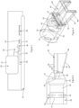
Figure 2 is a side view of a representative embodiment of the nozzle provided at the end of the coating apparatus. -
Figure 3 is a perspective view of the nozzle provided with the inverse U-shaped coating given inFigure 2 with the flow ducts. - In
Figure 1 , a coating apparatus used to coat marshmallow as a coating material (not shown) on a bar-shaped confectionery product (50) is shown schematically from the front. The coating apparatus comprises an endless transport conveyor (10) and a product supply device (20) disposed of on transfer line thereof. The product supply device (20) comprises a metal container (21) in accordance with the alimentary products regulations and a pump (22) provided underneath allowing the flow of coating material. Marshmallow is stored as a coating material in the container (21). In a possible embodiment, the container (21) is in a structure in which marshmallow is produced by mixing with a high-shear mixer and ventilating the components necessary for preparing marshmallows. The pump (22) continuously supplies the coating material to a header (30) in a pressurized state during operation. The header (30) transmits compressed and subsequently slightly expanded coating material to a nozzle (40) with a spout (44) secured at its end. The nozzle (40) extends to the transport conveyor (10) with a bending angle with respect to the direction of movement of the transport conveyor (10). The nozzle (40) is parallel to the confectionery product (50) transfer line. There is a distance between the lower end of the nozzle (40) and an elongated body (51) of the confectionery product (50). Thus, the coating material poured from the nozzle (40) is secured on the elongated body (51) to form a coating layer (52). The elongated body (51) has a cake structure and the porous structure on the outer wall of the cake helps the marshmallow, the coating material, to hold onto the elongated body (51). - In
Figure 2 , the header (30) equipped in the coating assembly and the nozzle (40) secured to the header (30) are shown from a cross-sectional view. The header (30) portion is in the form of a hollow cylinder of metal material, preferably stainless steel. An inlet part (31) of the header (30) is in a circular form cut-out at one end, and in the following an inner chamber (32) with a cylindrical gap of the same diameter extends coaxially. An adaptor hole (33) passes through the inner chamber (32) in the form of a through-hole in the radial outward direction, close to the inlet (31). At the opposite end of the inner chamber (32) opposite the inlet (31), there is a wide portion (34) with a larger diameter than the inlet (31 ). The end of the wide portion (34) is blind and in the middle, there is a narrowed port (35) in the form of a transverse slit. There is an outwardly curved dome (37) form around the narrowed port (35). The narrowed port (35) opens into the expansion chamber (36), the upper part of which is flat and the lower part of which is a rectangular trapezoidal gap that expands downward. The outer end of the expansion chamber (36) reaches an outlet (38) of the header. At the end of the header (30) carrying the outlet (38), the facing surfaces are narrowed towards the end with a curved flat form. A spout (44) part of the nozzle (40), which is aligned at the lower edge of the outlet (38), is secured around the outlet (38) by welding seal. An inlet port (41) of the nozzle (40) rests on the outlet (38) to provide fluid transmission with the narrowed port (35). An upper part (42), which is in the form of a flat plate and secured along one edge to the upper edge of the outlet (38), forms a duct (45) between them by covering the spout (44) from above. The spout (44) is double- walled and open-top inverted U-shaped and the duct (45) formed when it is covered with the upper part (42) is connected to the outlet (38) to provide fluid transmission from an inverted U- shaped inlet port (41). The spout (44) is in the form of a co-section which is narrow at the inlet port (41) and wide at an opposite discharge aperture (46). Thus, in the nozzle (40) where the upper part (42) is placed flat parallel to the extending axis of the inner chamber (32), the side extends outward in the form of a vertical trapezoid with a short edge at the inlet port (41). - In
Figure 3 , the header (30) and nozzle (40) used in the coating apparatus are shown in perspective. The inlet (31) carries the pressurized coating product from the container (21) to the inner chamber (32) with the help of the pump (22). The coating product, which moves to the wide portion (34) in the inner chamber (32) and is trapped at its blind end, accelerates through the narrowed port (35) and passes to the expansion chamber (36). Meanwhile, the fluid aerated coating product tends to fill the expanded part by moving radially outward as it is axially in a turbulent manner due to pressure loss. Air balloons remaining in the coating product are removed from the narrowed port (35) during the expansion. As the dome (37) wraps around the narrowed port, it was found that the covering product covers the expansion chamber (36) without any dead part as the radial outflow rate increases. The coating product that reaches the free end of the outlet (38) from the expansion chamber (36) is transferred to the confectionery product (50) by taking the opposite U-like form at the nozzle (40). The coating product moves from the narrow inlet port (41) towards the wide discharge aperture (46) with decreasing axial speed. Meanwhile, the marshmallow coating product moves along both the upper part and the legs of the U-form and fills the entire duct (45) that formed between them. As seen inFigure 1 , the bar-shaped elongated body (51) (in the form of cake or sandwich cake) adheres to the side walls and upper wall and slowly settling while the inverted U-shaped marshmallow coating product at the end of the angled header (30) passes underneath, with the inclination angle (a) and the direction of conveyor moving direction. A flap (not shown) disposed in the inlet (31), provides when the coating layer (52) is formed along the length of each elongated body (51), the product is transferred from the product supply apparatus (20) to the header (30) in the open state and cuts off the inlet (31) completely when the product is finished. A nozzle (40) is provided for each axial line of the elongated body (51) on the transport conveyor (10). Each nozzle (40) is equipped with a separate header (30). Headers (30) are fed in the product supply apparatus (20) with a single supply tube (not shown) to which the container (21) is connected to provide fluid transmission.REFERENCE NUMBERS 10 Transport conveyor 38 Outlet 20 Product supply apparatus 40 Nozzle 21 Container 41 Inlet port 22 Pump 42 Upper part 30 Header 44 Spout 31 Inlet 45 Duct 32 Inner chamber 46 Discharge aperture 33 Adaptor hole 48 Upper wall 34 Wide portion 50 Confectionery product 35 Narrowed port 51 Elongated body 36 Expansion chamber 52 Coating layer 37 Dome a Slope angle
Claims (9)
- A coating assembly comprising an endless transport conveyor (10) and a header (30) provided over a line of confectionery product (50) in bar form moving on the conveyor (10) one after another and is confining an inner chamber (32) having an outlet (38) through which a pressurized aerated semi-fluid edible coating material is transferred characterized in that a spout (44) is adapted to the outlet (38) and extending inwardly against line of the conveyor (10) such that the discharged coating material is surrounding at least partly the outer side of each confectionery product (50),an upper part (42) is disposed on the spout (44) at a distance to confine a closed duct (45) suitable for transferring the coating material and covering an inlet port (41) adapted to the outlet (38) in a sealed manner and a discharge aperture (46) at the opposing free end,the cross-section area of the outlet (38) is adjusted smaller than the cross-section area of the inlet port (41), andthe duct (45) is having a form expanding outwardly from the inlet port (41) to the discharge aperture (46).
- A coating assembly according to claim 1, wherein a duct (45) has an inverted U-like cross-sectional form.
- A coating apparatus according to claim 2, wherein a narrow bending angle is provided at the discharge aperture (46) against the transport conveyor (10) transfer axis.
- A coating apparatus according to claim 2 or 3, wherein the upper part (42) is having a flat upper wall (48) which is provided at the upper part of the duct (45).
- A coating apparatus according to any one of the preceding claims, the header (30) is having an inlet (31) accessing the inner chamber (32) and at least one narrowed port (35) through which the compressed coating material is forced to move under pressure and accessing to the outlet (38) from an end.
- A coating apparatus according to claim 5, wherein an expansion chamber (36) is extending between the narrowed port (35) and the outlet (38) in an expanding manner.
- A coating apparatus according to any one of the preceding claims, wherein the width of the spout (44) is at most 1% to 10% larger than the width of each confectionery product.
- A coating apparatus according to any one of the preceding claims, wherein the spout (44) is completely made of metal secured to the header (30) by means of with a welding seam.
- A coating apparatus according to any one of the preceding claims, wherein the spout (44) extends towards the plane of the conveyor (10) at an angle.
Priority Applications (2)
| Application Number | Priority Date | Filing Date | Title |
|---|---|---|---|
| HRP20250367TT HRP20250367T1 (en) | 2019-11-20 | 2020-06-26 | CONFECTIONERY COATING UNIT |
| RS20250307A RS66631B1 (en) | 2019-11-20 | 2020-06-26 | COATING ASSEMBLY FOR CONFECTIONERY PRODUCTS |
Applications Claiming Priority (2)
| Application Number | Priority Date | Filing Date | Title |
|---|---|---|---|
| TR2019/18144A TR201918144A2 (en) | 2019-11-20 | 2019-11-20 | CANDY PRODUCT COATING ASSEMBLY |
| PCT/TR2020/050549 WO2021101476A2 (en) | 2019-11-20 | 2020-06-26 | Confectionery product coating assembly |
Publications (3)
| Publication Number | Publication Date |
|---|---|
| EP4040976A2 EP4040976A2 (en) | 2022-08-17 |
| EP4040976A4 EP4040976A4 (en) | 2023-11-22 |
| EP4040976B1 true EP4040976B1 (en) | 2025-02-12 |
Family
ID=75980036
Family Applications (1)
| Application Number | Title | Priority Date | Filing Date |
|---|---|---|---|
| EP20889904.7A Active EP4040976B1 (en) | 2019-11-20 | 2020-06-26 | Confectionery product coating assembly |
Country Status (8)
| Country | Link |
|---|---|
| EP (1) | EP4040976B1 (en) |
| ES (1) | ES3018145T3 (en) |
| HR (1) | HRP20250367T1 (en) |
| HU (1) | HUE070595T2 (en) |
| PL (1) | PL4040976T3 (en) |
| RS (1) | RS66631B1 (en) |
| TR (1) | TR201918144A2 (en) |
| WO (1) | WO2021101476A2 (en) |
Citations (4)
| Publication number | Priority date | Publication date | Assignee | Title |
|---|---|---|---|---|
| GB700962A (en) | 1951-02-20 | 1953-12-16 | Earle Thomas Oakes | Method and apparatus for depositing marshmallow, dough, batters and the like |
| US4290989A (en) | 1979-12-10 | 1981-09-22 | Frito-Lay, Inc. | Method and apparatus for extruding a plurality of ribbons |
| US20020090437A1 (en) | 1999-04-22 | 2002-07-11 | Brown Peter Arthur | Confectionery coatings |
| WO2004098858A1 (en) | 2003-05-05 | 2004-11-18 | Bühler AG | Die for forming extrudates of viscoelastic materials (flared inlet) |
Family Cites Families (8)
| Publication number | Priority date | Publication date | Assignee | Title |
|---|---|---|---|---|
| GB191128069A (en) * | 1909-05-08 | 1912-09-26 | Emile Savy | Improvements in or relating to Machines for Icing or Coating Confectionery. |
| US1121431A (en) * | 1913-12-20 | 1914-12-15 | Frederick Westerman | Depositing-machine. |
| US1230455A (en) | 1914-10-16 | 1917-06-19 | Alonzo Linton Bausman | Coating apparatus. |
| US2696793A (en) | 1952-04-30 | 1954-12-14 | Et Oakes Corp | Method of eliminating the tips left by depositing marshmallow and the like on cookies, cakes, and confections |
| EP0411174B1 (en) * | 1989-08-01 | 1994-08-10 | Frisco-Findus Ag | Distribution device for coating foodstuffs |
| GB9325280D0 (en) * | 1993-12-10 | 1994-02-16 | United Biscuits Ltd | Improvements in and relating to coating food products |
| NL2020183B1 (en) * | 2017-12-27 | 2019-07-02 | Marel Further Proc Bv | Apparatus for coating a food product with a batter. |
| TR201915738U5 (en) | 2019-10-13 | 2021-04-21 | Soelen Cikolata Gida Sanayi Ve Ticaret Anonim Sirketi | A CONFECTIONERY PRODUCT WITH MARSHMELOV COVER |
-
2019
- 2019-11-20 TR TR2019/18144A patent/TR201918144A2/en unknown
-
2020
- 2020-06-26 ES ES20889904T patent/ES3018145T3/en active Active
- 2020-06-26 HR HRP20250367TT patent/HRP20250367T1/en unknown
- 2020-06-26 RS RS20250307A patent/RS66631B1/en unknown
- 2020-06-26 WO PCT/TR2020/050549 patent/WO2021101476A2/en not_active Ceased
- 2020-06-26 HU HUE20889904A patent/HUE070595T2/en unknown
- 2020-06-26 PL PL20889904.7T patent/PL4040976T3/en unknown
- 2020-06-26 EP EP20889904.7A patent/EP4040976B1/en active Active
Patent Citations (4)
| Publication number | Priority date | Publication date | Assignee | Title |
|---|---|---|---|---|
| GB700962A (en) | 1951-02-20 | 1953-12-16 | Earle Thomas Oakes | Method and apparatus for depositing marshmallow, dough, batters and the like |
| US4290989A (en) | 1979-12-10 | 1981-09-22 | Frito-Lay, Inc. | Method and apparatus for extruding a plurality of ribbons |
| US20020090437A1 (en) | 1999-04-22 | 2002-07-11 | Brown Peter Arthur | Confectionery coatings |
| WO2004098858A1 (en) | 2003-05-05 | 2004-11-18 | Bühler AG | Die for forming extrudates of viscoelastic materials (flared inlet) |
Also Published As
| Publication number | Publication date |
|---|---|
| EP4040976A2 (en) | 2022-08-17 |
| TR201918144A2 (en) | 2021-06-21 |
| WO2021101476A3 (en) | 2021-10-14 |
| RS66631B1 (en) | 2025-04-30 |
| WO2021101476A2 (en) | 2021-05-27 |
| ES3018145T3 (en) | 2025-05-14 |
| HRP20250367T1 (en) | 2025-06-06 |
| HUE070595T2 (en) | 2025-06-28 |
| PL4040976T3 (en) | 2025-04-28 |
| EP4040976A4 (en) | 2023-11-22 |
Similar Documents
| Publication | Publication Date | Title |
|---|---|---|
| US6543248B2 (en) | Apparatus for molding frozen confectionery compositions into articles | |
| US6758056B1 (en) | Apparatus and process for molding frozen ice confectionery compositions into articles | |
| EP0554707B1 (en) | Device and method of applying coatings of flowable substances | |
| AU767591B2 (en) | A process for making a baked cup shaped food product | |
| US5843512A (en) | Preparation of chocolate-coated frozen confectionary articles | |
| US8784091B2 (en) | Co-extrusion of food material and product resulting thereof | |
| CA2638193C (en) | Method for producing a confectionery product | |
| US6047858A (en) | Pastry dough or cake decorating device | |
| US4932317A (en) | Process and device for preparation of a multilayer confectionery product and confectionery product | |
| US8658233B2 (en) | Apparatus for depositing a confectionery mass, and method of producing a confectionery product | |
| EP4040976B1 (en) | Confectionery product coating assembly | |
| JP3164768B2 (en) | Food dough discharging device | |
| EP3888469B1 (en) | Food production line, depositor and nozzles for confectionery articles | |
| EP0908092B1 (en) | Method for producing flat blocks of butter or foodstuffs of similar consistency and flat blocks of foodstuff | |
| JP7661089B2 (en) | Food manufacturing equipment and food manufacturing method | |
| AU2018265195B2 (en) | Method and apparatus for preparing an edible food composition | |
| EP4154719A1 (en) | Edible dough walled cake product that does not require a cooking pan and baking paper, and production method thereof | |
| US20200205437A1 (en) | Coated stuffed pretzel and method of making a coated stuffed pretzel from an already baked pretzel | |
| MXPA99004374A (en) | Process and device for molding congela store items | |
| JP5777985B2 (en) | Confectionery production equipment | |
| HK1124999A (en) | Co-extrusion of food material and product resulting thereof |
Legal Events
| Date | Code | Title | Description |
|---|---|---|---|
| REG | Reference to a national code |
Ref country code: HR Ref legal event code: TUEP Ref document number: P20250367T Country of ref document: HR |
|
| STAA | Information on the status of an ep patent application or granted ep patent |
Free format text: STATUS: THE INTERNATIONAL PUBLICATION HAS BEEN MADE |
|
| PUAI | Public reference made under article 153(3) epc to a published international application that has entered the european phase |
Free format text: ORIGINAL CODE: 0009012 |
|
| STAA | Information on the status of an ep patent application or granted ep patent |
Free format text: STATUS: REQUEST FOR EXAMINATION WAS MADE |
|
| 17P | Request for examination filed |
Effective date: 20220510 |
|
| AK | Designated contracting states |
Kind code of ref document: A2 Designated state(s): AL AT BE BG CH CY CZ DE DK EE ES FI FR GB GR HR HU IE IS IT LI LT LU LV MC MK MT NL NO PL PT RO RS SE SI SK SM TR |
|
| DAV | Request for validation of the european patent (deleted) | ||
| DAX | Request for extension of the european patent (deleted) | ||
| A4 | Supplementary search report drawn up and despatched |
Effective date: 20231019 |
|
| RIC1 | Information provided on ipc code assigned before grant |
Ipc: A23P 20/15 20160101ALI20231013BHEP Ipc: A23G 3/52 20060101ALI20231013BHEP Ipc: A23G 3/20 20060101ALI20231013BHEP Ipc: A23G 3/00 20060101AFI20231013BHEP |
|
| GRAP | Despatch of communication of intention to grant a patent |
Free format text: ORIGINAL CODE: EPIDOSNIGR1 |
|
| STAA | Information on the status of an ep patent application or granted ep patent |
Free format text: STATUS: GRANT OF PATENT IS INTENDED |
|
| INTG | Intention to grant announced |
Effective date: 20241008 |
|
| GRAS | Grant fee paid |
Free format text: ORIGINAL CODE: EPIDOSNIGR3 |
|
| GRAA | (expected) grant |
Free format text: ORIGINAL CODE: 0009210 |
|
| STAA | Information on the status of an ep patent application or granted ep patent |
Free format text: STATUS: THE PATENT HAS BEEN GRANTED |
|
| AK | Designated contracting states |
Kind code of ref document: B1 Designated state(s): AL AT BE BG CH CY CZ DE DK EE ES FI FR GB GR HR HU IE IS IT LI LT LU LV MC MK MT NL NO PL PT RO RS SE SI SK SM TR |
|
| REG | Reference to a national code |
Ref country code: GB Ref legal event code: FG4D |
|
| REG | Reference to a national code |
Ref country code: CH Ref legal event code: EP |
|
| REG | Reference to a national code |
Ref country code: DE Ref legal event code: R096 Ref document number: 602020046111 Country of ref document: DE |
|
| REG | Reference to a national code |
Ref country code: IE Ref legal event code: FG4D |
|
| REG | Reference to a national code |
Ref country code: SK Ref legal event code: T3 Ref document number: E 46194 Country of ref document: SK |
|
| REG | Reference to a national code |
Ref country code: HR Ref legal event code: T1PR Ref document number: P20250367 Country of ref document: HR |
|
| REG | Reference to a national code |
Ref country code: NL Ref legal event code: MP Effective date: 20250212 |
|
| REG | Reference to a national code |
Ref country code: HU Ref legal event code: AG4A Ref document number: E070595 Country of ref document: HU |
|
| REG | Reference to a national code |
Ref country code: HR Ref legal event code: ODRP Ref document number: P20250367 Country of ref document: HR Payment date: 20250606 Year of fee payment: 6 |
|
| PG25 | Lapsed in a contracting state [announced via postgrant information from national office to epo] |
Ref country code: FI Free format text: LAPSE BECAUSE OF FAILURE TO SUBMIT A TRANSLATION OF THE DESCRIPTION OR TO PAY THE FEE WITHIN THE PRESCRIBED TIME-LIMIT Effective date: 20250212 |
|
| PGFP | Annual fee paid to national office [announced via postgrant information from national office to epo] |
Ref country code: PL Payment date: 20250603 Year of fee payment: 6 |
|
| PGFP | Annual fee paid to national office [announced via postgrant information from national office to epo] |
Ref country code: GB Payment date: 20250530 Year of fee payment: 6 |
|
| REG | Reference to a national code |
Ref country code: LT Ref legal event code: MG9D |
|
| PG25 | Lapsed in a contracting state [announced via postgrant information from national office to epo] |
Ref country code: NO Free format text: LAPSE BECAUSE OF FAILURE TO SUBMIT A TRANSLATION OF THE DESCRIPTION OR TO PAY THE FEE WITHIN THE PRESCRIBED TIME-LIMIT Effective date: 20250512 Ref country code: IS Free format text: LAPSE BECAUSE OF FAILURE TO SUBMIT A TRANSLATION OF THE DESCRIPTION OR TO PAY THE FEE WITHIN THE PRESCRIBED TIME-LIMIT Effective date: 20250612 |
|
| PGFP | Annual fee paid to national office [announced via postgrant information from national office to epo] |
Ref country code: RS Payment date: 20250604 Year of fee payment: 6 |
|
| PG25 | Lapsed in a contracting state [announced via postgrant information from national office to epo] |
Ref country code: NL Free format text: LAPSE BECAUSE OF FAILURE TO SUBMIT A TRANSLATION OF THE DESCRIPTION OR TO PAY THE FEE WITHIN THE PRESCRIBED TIME-LIMIT Effective date: 20250212 |
|
| PGFP | Annual fee paid to national office [announced via postgrant information from national office to epo] |
Ref country code: HR Payment date: 20250606 Year of fee payment: 6 |
|
| PG25 | Lapsed in a contracting state [announced via postgrant information from national office to epo] |
Ref country code: PT Free format text: LAPSE BECAUSE OF FAILURE TO SUBMIT A TRANSLATION OF THE DESCRIPTION OR TO PAY THE FEE WITHIN THE PRESCRIBED TIME-LIMIT Effective date: 20250612 Ref country code: LV Free format text: LAPSE BECAUSE OF FAILURE TO SUBMIT A TRANSLATION OF THE DESCRIPTION OR TO PAY THE FEE WITHIN THE PRESCRIBED TIME-LIMIT Effective date: 20250212 |
|
| PGFP | Annual fee paid to national office [announced via postgrant information from national office to epo] |
Ref country code: HU Payment date: 20250606 Year of fee payment: 6 |
|
| PG25 | Lapsed in a contracting state [announced via postgrant information from national office to epo] |
Ref country code: GR Free format text: LAPSE BECAUSE OF FAILURE TO SUBMIT A TRANSLATION OF THE DESCRIPTION OR TO PAY THE FEE WITHIN THE PRESCRIBED TIME-LIMIT Effective date: 20250513 Ref country code: BG Free format text: LAPSE BECAUSE OF FAILURE TO SUBMIT A TRANSLATION OF THE DESCRIPTION OR TO PAY THE FEE WITHIN THE PRESCRIBED TIME-LIMIT Effective date: 20250212 |
|
| PGFP | Annual fee paid to national office [announced via postgrant information from national office to epo] |
Ref country code: TR Payment date: 20250526 Year of fee payment: 6 Ref country code: SK Payment date: 20250624 Year of fee payment: 6 |
|
| PGFP | Annual fee paid to national office [announced via postgrant information from national office to epo] |
Ref country code: CZ Payment date: 20250602 Year of fee payment: 6 |
|
| REG | Reference to a national code |
Ref country code: AT Ref legal event code: MK05 Ref document number: 1765151 Country of ref document: AT Kind code of ref document: T Effective date: 20250212 |
|
| PG25 | Lapsed in a contracting state [announced via postgrant information from national office to epo] |
Ref country code: SE Free format text: LAPSE BECAUSE OF FAILURE TO SUBMIT A TRANSLATION OF THE DESCRIPTION OR TO PAY THE FEE WITHIN THE PRESCRIBED TIME-LIMIT Effective date: 20250212 |
|
| PG25 | Lapsed in a contracting state [announced via postgrant information from national office to epo] |
Ref country code: SM Free format text: LAPSE BECAUSE OF FAILURE TO SUBMIT A TRANSLATION OF THE DESCRIPTION OR TO PAY THE FEE WITHIN THE PRESCRIBED TIME-LIMIT Effective date: 20250212 |
|
| PGFP | Annual fee paid to national office [announced via postgrant information from national office to epo] |
Ref country code: ES Payment date: 20250701 Year of fee payment: 6 |
|
| PG25 | Lapsed in a contracting state [announced via postgrant information from national office to epo] |
Ref country code: DK Free format text: LAPSE BECAUSE OF FAILURE TO SUBMIT A TRANSLATION OF THE DESCRIPTION OR TO PAY THE FEE WITHIN THE PRESCRIBED TIME-LIMIT Effective date: 20250212 |
|
| PG25 | Lapsed in a contracting state [announced via postgrant information from national office to epo] |
Ref country code: IT Free format text: LAPSE BECAUSE OF FAILURE TO SUBMIT A TRANSLATION OF THE DESCRIPTION OR TO PAY THE FEE WITHIN THE PRESCRIBED TIME-LIMIT Effective date: 20250212 |
|
| PG25 | Lapsed in a contracting state [announced via postgrant information from national office to epo] |
Ref country code: AT Free format text: LAPSE BECAUSE OF FAILURE TO SUBMIT A TRANSLATION OF THE DESCRIPTION OR TO PAY THE FEE WITHIN THE PRESCRIBED TIME-LIMIT Effective date: 20250212 |
|
| PG25 | Lapsed in a contracting state [announced via postgrant information from national office to epo] |
Ref country code: EE Free format text: LAPSE BECAUSE OF FAILURE TO SUBMIT A TRANSLATION OF THE DESCRIPTION OR TO PAY THE FEE WITHIN THE PRESCRIBED TIME-LIMIT Effective date: 20250212 |
|
| PG25 | Lapsed in a contracting state [announced via postgrant information from national office to epo] |
Ref country code: RO Free format text: LAPSE BECAUSE OF FAILURE TO SUBMIT A TRANSLATION OF THE DESCRIPTION OR TO PAY THE FEE WITHIN THE PRESCRIBED TIME-LIMIT Effective date: 20250212 |
|
| REG | Reference to a national code |
Ref country code: DE Ref legal event code: R026 Ref document number: 602020046111 Country of ref document: DE |
|
| PLBI | Opposition filed |
Free format text: ORIGINAL CODE: 0009260 |
|
| REG | Reference to a national code |
Ref country code: CH Ref legal event code: L11 Free format text: ST27 STATUS EVENT CODE: U-0-0-L10-L11 (AS PROVIDED BY THE NATIONAL OFFICE) Effective date: 20251119 |
|
| PLAB | Opposition data, opponent's data or that of the opponent's representative modified |
Free format text: ORIGINAL CODE: 0009299OPPO |
|
| PLAX | Notice of opposition and request to file observation + time limit sent |
Free format text: ORIGINAL CODE: EPIDOSNOBS2 |
|
| REG | Reference to a national code |
Ref country code: CH Ref legal event code: L10 Free format text: ST27 STATUS EVENT CODE: U-0-0-L10-L00 (AS PROVIDED BY THE NATIONAL OFFICE) Effective date: 20251126 |
|
| 26 | Opposition filed |
Opponent name: ELVAN GIDA SANAYI VE TICARET A.S Effective date: 20251110 |
|
| R26 | Opposition filed (corrected) |
Opponent name: ELVAN GIDA SANAYI VE TICARET A.S Effective date: 20251110 |
|
| REG | Reference to a national code |
Ref country code: DE Ref legal event code: R119 Ref document number: 602020046111 Country of ref document: DE |
|
| REG | Reference to a national code |
Ref country code: CH Ref legal event code: H13 Free format text: ST27 STATUS EVENT CODE: U-0-0-H10-H13 (AS PROVIDED BY THE NATIONAL OFFICE) Effective date: 20260127 |
|
| PG25 | Lapsed in a contracting state [announced via postgrant information from national office to epo] |
Ref country code: MC Free format text: LAPSE BECAUSE OF FAILURE TO SUBMIT A TRANSLATION OF THE DESCRIPTION OR TO PAY THE FEE WITHIN THE PRESCRIBED TIME-LIMIT Effective date: 20250212 |
|
| PG25 | Lapsed in a contracting state [announced via postgrant information from national office to epo] |
Ref country code: LU Free format text: LAPSE BECAUSE OF NON-PAYMENT OF DUE FEES Effective date: 20250626 |
|
| REG | Reference to a national code |
Ref country code: BE Ref legal event code: MM Effective date: 20250630 |
|
| PLBB | Reply of patent proprietor to notice(s) of opposition received |
Free format text: ORIGINAL CODE: EPIDOSNOBS3 |