EP4040908B1 - Verfahren zum empfangen eines downlink-signals durch ein endgerät auf der basis eines zufallszugriffskanalverfahrens, und gerät dafür - Google Patents
Verfahren zum empfangen eines downlink-signals durch ein endgerät auf der basis eines zufallszugriffskanalverfahrens, und gerät dafür Download PDFInfo
- Publication number
- EP4040908B1 EP4040908B1 EP20873139.8A EP20873139A EP4040908B1 EP 4040908 B1 EP4040908 B1 EP 4040908B1 EP 20873139 A EP20873139 A EP 20873139A EP 4040908 B1 EP4040908 B1 EP 4040908B1
- Authority
- EP
- European Patent Office
- Prior art keywords
- msg
- pusch
- channel
- base station
- message
- Prior art date
- Legal status (The legal status is an assumption and is not a legal conclusion. Google has not performed a legal analysis and makes no representation as to the accuracy of the status listed.)
- Active
Links
Images


Classifications
-
- H—ELECTRICITY
- H04—ELECTRIC COMMUNICATION TECHNIQUE
- H04W—WIRELESS COMMUNICATION NETWORKS
- H04W72/00—Local resource management
- H04W72/04—Wireless resource allocation
- H04W72/044—Wireless resource allocation based on the type of the allocated resource
- H04W72/0453—Resources in frequency domain, e.g. a carrier in FDMA
-
- H—ELECTRICITY
- H04—ELECTRIC COMMUNICATION TECHNIQUE
- H04L—TRANSMISSION OF DIGITAL INFORMATION, e.g. TELEGRAPHIC COMMUNICATION
- H04L1/00—Arrangements for detecting or preventing errors in the information received
-
- H—ELECTRICITY
- H04—ELECTRIC COMMUNICATION TECHNIQUE
- H04W—WIRELESS COMMUNICATION NETWORKS
- H04W16/00—Network planning, e.g. coverage or traffic planning tools; Network deployment, e.g. resource partitioning or cells structures
- H04W16/14—Spectrum sharing arrangements between different networks
-
- H—ELECTRICITY
- H04—ELECTRIC COMMUNICATION TECHNIQUE
- H04W—WIRELESS COMMUNICATION NETWORKS
- H04W52/00—Power management, e.g. Transmission Power Control [TPC] or power classes
- H04W52/02—Power saving arrangements
-
- H—ELECTRICITY
- H04—ELECTRIC COMMUNICATION TECHNIQUE
- H04W—WIRELESS COMMUNICATION NETWORKS
- H04W52/00—Power management, e.g. Transmission Power Control [TPC] or power classes
- H04W52/02—Power saving arrangements
- H04W52/0209—Power saving arrangements in terminal devices
- H04W52/0212—Power saving arrangements in terminal devices managed by the network, e.g. network or access point is leader and terminal is follower
- H04W52/0216—Power saving arrangements in terminal devices managed by the network, e.g. network or access point is leader and terminal is follower using a pre-established activity schedule, e.g. traffic indication frame
-
- H—ELECTRICITY
- H04—ELECTRIC COMMUNICATION TECHNIQUE
- H04W—WIRELESS COMMUNICATION NETWORKS
- H04W72/00—Local resource management
- H04W72/12—Wireless traffic scheduling
- H04W72/1263—Mapping of traffic onto schedule, e.g. scheduled allocation or multiplexing of flows
- H04W72/1268—Mapping of traffic onto schedule, e.g. scheduled allocation or multiplexing of flows of uplink data flows
-
- H—ELECTRICITY
- H04—ELECTRIC COMMUNICATION TECHNIQUE
- H04W—WIRELESS COMMUNICATION NETWORKS
- H04W72/00—Local resource management
- H04W72/20—Control channels or signalling for resource management
- H04W72/23—Control channels or signalling for resource management in the downlink direction of a wireless link, i.e. towards a terminal
-
- H—ELECTRICITY
- H04—ELECTRIC COMMUNICATION TECHNIQUE
- H04W—WIRELESS COMMUNICATION NETWORKS
- H04W72/00—Local resource management
- H04W72/50—Allocation or scheduling criteria for wireless resources
- H04W72/535—Allocation or scheduling criteria for wireless resources based on resource usage policies
-
- H—ELECTRICITY
- H04—ELECTRIC COMMUNICATION TECHNIQUE
- H04W—WIRELESS COMMUNICATION NETWORKS
- H04W74/00—Wireless channel access
- H04W74/002—Transmission of channel access control information
- H04W74/004—Transmission of channel access control information in the uplink, i.e. towards network
-
- H—ELECTRICITY
- H04—ELECTRIC COMMUNICATION TECHNIQUE
- H04W—WIRELESS COMMUNICATION NETWORKS
- H04W74/00—Wireless channel access
- H04W74/002—Transmission of channel access control information
- H04W74/006—Transmission of channel access control information in the downlink, i.e. towards the terminal
-
- H—ELECTRICITY
- H04—ELECTRIC COMMUNICATION TECHNIQUE
- H04W—WIRELESS COMMUNICATION NETWORKS
- H04W74/00—Wireless channel access
- H04W74/08—Non-scheduled access, e.g. ALOHA
- H04W74/0808—Non-scheduled access, e.g. ALOHA using carrier sensing, e.g. carrier sense multiple access [CSMA]
-
- H—ELECTRICITY
- H04—ELECTRIC COMMUNICATION TECHNIQUE
- H04W—WIRELESS COMMUNICATION NETWORKS
- H04W74/00—Wireless channel access
- H04W74/08—Non-scheduled access, e.g. ALOHA
- H04W74/0833—Random access procedures, e.g. with 4-step access
-
- H—ELECTRICITY
- H04—ELECTRIC COMMUNICATION TECHNIQUE
- H04W—WIRELESS COMMUNICATION NETWORKS
- H04W76/00—Connection management
- H04W76/20—Manipulation of established connections
- H04W76/28—Discontinuous transmission [DTX]; Discontinuous reception [DRX]
-
- H—ELECTRICITY
- H04—ELECTRIC COMMUNICATION TECHNIQUE
- H04W—WIRELESS COMMUNICATION NETWORKS
- H04W74/00—Wireless channel access
- H04W74/08—Non-scheduled access, e.g. ALOHA
- H04W74/0833—Random access procedures, e.g. with 4-step access
- H04W74/0836—Random access procedures, e.g. with 4-step access with 2-step access
-
- H—ELECTRICITY
- H04—ELECTRIC COMMUNICATION TECHNIQUE
- H04W—WIRELESS COMMUNICATION NETWORKS
- H04W74/00—Wireless channel access
- H04W74/08—Non-scheduled access, e.g. ALOHA
- H04W74/0833—Random access procedures, e.g. with 4-step access
- H04W74/0838—Random access procedures, e.g. with 4-step access using contention-free random access [CFRA]
Definitions
- Smart cities and smart homes referred to as smart societies, will be embedded with high-density wireless sensor networks.
- a distributed network of intelligent sensors will identify conditions for cost and energy-efficient maintenance of a city or house.
- a similar setup can be performed for each household.
- Temperature sensors, window and heating controllers, burglar alarms and appliances are all connected wirelessly. Many of these sensors are typically low data rates, low power and low cost. However, for example, real-time HD video may be required in certain types of devices for surveillance.
- Wireless and mobile communications are becoming increasingly important in industrial applications. Wiring is expensive to install and maintain. Thus, the possibility of replacing cables with reconfigurable wireless links is an attractive opportunity for many industries. Achieving this, however, requires that the wireless connection operate with cable-like delay, reliability and capacity, and that its management be simplified. Low latency and very low error probability are new requirements that need to be connected with 5G.
- Logistics and freight tracking are important use cases for mobile communications that enable tracking of inventory and packages from anywhere using location-based information systems.
- Logistics and freight tracking use cases typically require low data rates but require wide range and reliable location information.
- the RAR is a fallback RAR including uplink (UL) grant information.
- the PUSCH occasion may be a valid PUSCH occasion related to a RACH occasion for the first PRACH preamble.
- the window may start at a first symbol of a resource related to monitoring of the message B.
- a terminal for receiving a downlink signal based on a random access channel (RACH) procedure comprises at least one transceiver; at least one processor; and at least one memory operably connected to the at least one processor, and storing instructions that, based on being executed by the at least one processor, perform specific operations, wherein the specific operations comprises transmitting a first physical random access channel (PRACH) preamble through a message A to a base station, receiving a random access response (RAR) through a message B from the base station, in response to the message A, receiving information on at least one discontinuous reception (DRX) timer for configuration of DRX operation from the base station, and receiving a downlink signal during an on duration based on the at least one DRX timer from the base station, wherein the first PRACH preamble is a PRACH preamble mapped to a physical uplink shared channel (PUSCH) occasion for the message A, wherein a window for receiving the message B starts at least one symbol after a last symbol of the message
- PUSCH
- a reference signal also referred to as a pilot, refers to a signal of a predefined special waveform that the gNB and the UE know each other, for example, cell specific RS (RS), UE-specific RS (UE-RS), a positioning RS (PRS), and a channel state information RS (CSI-RS) are defined as downlink reference signals.
- RS cell specific RS
- UE-RS UE-specific RS
- PRS positioning RS
- CSI-RS channel state information RS
- the 3GPP LTE/LTE-A standard defines uplink physical channels corresponding to resource elements carrying information originated from a higher layer, and uplink physical signals corresponding to resource elements used by the physical layer but not carrying information originated from a higher layer.
- a physical uplink shared channel (PUSCH), a physical uplink control channel (PUCCH), and a physical random access channel (PRACH) are defined as uplink physical channels
- a demodulation reference signal (DMRS) for an uplink control/data signal and a sounding reference signal (SRS) used for uplink channel measurement are defined.
- DMRS demodulation reference signal
- SRS sounding reference signal
- PDCCH Physical Downlink Control CHannel
- PCFICH Physical Control Format Indicator CHannel
- PHICH Physical Hybrid automatic retransmit request Indicator CHannel
- PDSCH Physical Downlink Shared CHannel
- DCI Downlink Control Information
- CFI Control Format Indicator
- Downlink ACK/NACK ACKnowlegement/Negative ACK
- PUCCH Physical Uplink Control CHannel
- PUSCH Physical Uplink Shared CHannel
- PRACH Physical Random Access CHannel
- PDCCH Physical Uplink Control CHannel
- PUSCH Physical Uplink Shared CHannel
- PRACH Physical Random Access CHannel
- time-frequency resource or resource element (RE) allocated to or belonging to PDCCH/PCFICH/PHICH/PDSCH/PUCCH/PUSCH/PRACH is respectively referred to as PDCCH/PCFICH/PHICH/PDSCH/PUCCH/PUSCH/PRACH RE or PDCCH/PCFICH/PHICH/PDSCH/PUCCH/PUSCH/PRACH resource.
- the expression that a user equipment transmits PUCCH/PUSCH/PRACH, respectively, is used in the same meaning as transmitting uplink control information/uplink data/random access signal on or through the PUSCH/PUCCH/PRACH.
- the expression that gNB transmits PDCCH/PCFICH/PHICH/PDSCH, respectively, is used in the same meaning as transmitting downlink data/control information on or through PDCCH/PCFICH/PHICH/PDSCH.
- OFDM symbol/subcarrier/RE to which CRS/DMRS/CSI-RS/SRS/UE-RS is assigned or configured is referred to as CRS/DMRS/CSI-RS/SRS/UE-RS symbol/carrier/subcarrier/RE.
- CRS/DMRS/CSI-RS/SRS/UE-RS symbol/carrier/subcarrier/RE For example, an OFDM symbol to which a tracking RS (TRS) is allocated or configured is referred to as a TRS symbol, and a subcarrier to which TRS is allocated or configured is referred to as a TRS subcarrier, and an RE to which TRS is allocated or configured is referred to as a TRS RE.
- TRS subframe configured for TRS transmission is referred to as a TRS subframe.
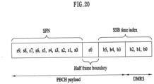
- a subframe in which a broadcast signal is transmitted is referred to as a broadcast subframe or a PBCH subframe
- a subframe in which a synchronization signal (e.g., PSS and/or SSS) is transmitted is referred to as a synchronization signal subframe or PSS/SSS subframe.
- An OFDM symbol/subcarrier/RE to which PSS/SSS is allocated or configured is referred to as a PSS/SSS symbol/subcarrier/RE, respectively.
- CRS port, UE-RS port, CSI-RS port, and TRS port respectively, means an antenna port configured to transmit CRS, an antenna port configured to transmit UE-RS, an antenna port configured to transmit CSI-RS, and an antenna port configured to transmit TRS.
- Antenna ports configured to transmit CRSs may be distinguished from each other by positions of REs occupied by CRSs according to CRS ports, and antenna ports configured to transmit UE-RSs may be distinguished from each other by positions of REs occupied by the UE-RSs according to UE-RS ports, and antenna ports configured to transmit CSI-RSs may be distinguished from each other by positions of REs occupied by the CSI-RSs according to CSI-RS ports. Therefore, the term CRS/UE-RS/CSI-RS/TRS port is also used as a term meaning a pattern of REs occupied by CRS/UE-RS/CSI-RS/TRS within a certain resource region.
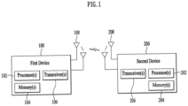
- FIG. 1 illustrates wireless devices to which the present disclosure is applied.
- the first wireless device 100 and the second wireless device 200 may transmit/receive wireless signals through various wireless access technologies (e.g., LTE, NR).
- ⁇ first wireless device 100, second wireless device 200 ⁇ may correspond to ⁇ wireless device 100x, base station 200 ⁇ and/or ⁇ wireless device 100x, wireless device 100x ⁇ of FIG. 30 .
- the first wireless device 100 includes one or more processors 102 and one or more memories 104, and may further include one or more transceivers 106 and/or one or more antennas 108.
- the processor 102 controls the memory 104 and/or the transceiver 106 and may be configured to implement the descriptions, functions, procedures, suggestions, methods, and/or operational flow charts disclosed herein.
- the processor 102 may process information in the memory 104 to generate first information/signal, and then transmit a wireless signal including the first information/signal through the transceiver 106 .
- the processor 102 may receive the radio signal including the second information/signal through the transceiver 106, and then store the information obtained from the signal processing of the second information/signal in the memory 104 .
- the memory 104 may be connected to the processor 102 and may store various information related to the operation of the processor 102.
- the memory 104 may store software code including instructions for performing some or all of processes controlled by the processor 102, or for performing the descriptions, functions, procedures, suggestions, methods, and/or operational flowcharts disclosed in the document.
- the processor 102 and the memory 104 may be part of a communication modem/circuit/chip designed to implement a wireless communication technology (e.g., LTE, NR).
- a transceiver 106 may be coupled to the processor 102 and may transmit and/or receive wireless signals via one or more antennas 108 .
- the transceiver 106 may include a transmitter and/or a receiver.
- the transceiver 106 may be used interchangeably with a radio frequency (RF) unit.
- a wireless device may refer to a communication modem/circuit/chip.
- the following operations are described based on the control operation of the processor 102 from the perspective of the processor 102, but may be stored in the memory 104, such as software code for performing these operations.
- the processor 102 may control the transceiver 106 to transmit a first Physical Random Access Channel (PRACH) preamble through message A. And the processor 102 may control the transceiver 106 to receive a random access response (RAR) through message B related to contention resolution.
- PRACH Physical Random Access Channel
- RAR random access response
- a specific method for the processor 102 to control the transceiver 106 to transmit the message A and to control the transceiver 106 to receive the message B may be based on the following examples.
- the following operations are described based on the control operation of the processor 202 from the perspective of the processor 202, but may be stored in the memory 204, such as software code for performing these operations.
- the processor 202 may control the transceiver 206 to receive the first Physical Random Access Channel (PRACH) preamble through message A. And the processor 202 may control the transceiver 206 to transmit a random access response (RAR) through message B related to contention resolution.
- PRACH Physical Random Access Channel
- RAR random access response
- a specific method for the processor 202 to control the transceiver 206 to receive the message A and to control the transceiver 206 to transmit the message B may be based on the following examples.
- one or more protocol layers may be implemented by one or more processors 102, 202.
- one or more processors 102, 202 may implement one or more layers (e.g., functional layers such as PHY, MAC, RLC, PDCP, RRC, SDAP).
- the one or more processors 102, 202 may generate one or more Protocol Data Units (PDUs) and/or one or more Service Data Units (SDUs) according to the description, function, procedure, proposal, method and/or operational flowcharts disclosed herein.
- PDUs Protocol Data Units
- SDUs Service Data Units
- One or more processors 102 , 202 may generate messages, control information, data, or information according to the description, function, procedure, proposal, method, and/or flow charts disclosed herein.
- the one or more processors 102 and 202 generate a signal (e.g., a baseband signal) including PDUs, SDUs, messages, control information, data or information according to the functions, procedures, proposals and/or methods disclosed herein and provide it to one or more transceivers 106 and 206.
- One or more processors 102, 202 may receive signals (e.g., baseband signals) from one or more transceivers 106, 206, and may obtain PDUs, SDUs, messages, control information, data, or information according to description, functions, procedures, proposals, methods, and/or operational flowcharts disclosed herein.
- signals e.g., baseband signals
- transceivers 106, 206 may obtain PDUs, SDUs, messages, control information, data, or information according to description, functions, procedures, proposals, methods, and/or operational flowcharts disclosed herein.
- firmware or software may be implemented using firmware or software, and the firmware or software may be implemented to include modules, procedures, functions, and the like.
- Firmware or software configured to perform the descriptions, functions, procedures, suggestions, methods, and/or flow charts disclosed herein may be included in one or more processors 102, 202 or may be stored in one or more memories 104, 204 and driven by one or more processors 102, 202.
- the descriptions, functions, procedures, suggestions, methods, and/or flowcharts of operations disclosed herein may be implemented using firmware or software in the form of code, instructions, and/or a set of instructions.
- One or more memories 104, 204 may be coupled to one or more processors 102, 202 and may store various forms of data, signals, messages, information, programs, codes, instructions, and/or instructions.
- One or more memories 104, 204 may be comprised of ROM, RAM, EPROM, flash memory, hard drives, registers, cache memory, computer readable storage media, and/or combinations thereof.
- One or more memories 104 , 204 may be located inside and/or external to one or more processors 102 , 202 . Additionally, one or more memories 104, 204 may be coupled to one or more processors 102, 202 through various technologies, such as wired or wireless connections.
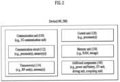
- the control unit 120 is electrically connected to the communication unit 110, the memory unit 130, and the additional element 140, and controls general operations of the wireless device. For example, the controller 120 may control the electrical/mechanical operation of the wireless device based on the program/code/command/information stored in the memory unit 130. In addition, the control unit 120 may transmit the information stored in the memory unit 130 to the outside(e.g., another communication device) through the communication unit 110 through a wireless/wired interface, or may store information received from the outside (e.g., another communication device) through a wireless/wired interface through the communication unit 110 in the memory unit 130.
- the outside e.g., another communication device
- the control unit 120 may transmit the information stored in the memory unit 130 to the outside(e.g., another communication device) through the communication unit 110 through a wireless/wired interface, or may store information received from the outside (e.g., another communication device) through a wireless/wired interface through the communication unit 110 in the memory unit 130.
- control unit 120 may be configured as a set of a communication control processor, an application processor, an electronic control unit (ECU), a graphic processing processor, a memory control processor, and the like.
- memory unit 130 may include random access memory (RAM), dynamic RAM (DRAM), read only memory (ROM), flash memory, volatile memory, and non-volatile memory, volatile memory) and/or a combination thereof.
- the communication unit 110 may transmit and receive signals (e.g., data, control signals, etc.) with other wireless devices and base stations.
- the controller 120 may perform various operations by controlling the components of the portable device 100.
- the controller 120 may include an application processor (AP).
- the memory unit 130 may store data/parameters/programs/codes/commands necessary for driving the portable device 100. Also, the memory unit 130 may store input/output data/information.
- the power supply unit 140a supplies power to the portable device 100 and may include a wired/wireless charging circuit, a battery, and the like.
- the interface unit 140b may support a connection between the portable device 100 and other external devices.
- the interface unit 140b may include various ports (e.g., an audio input/output port and a video input/output port) for connection with an external device.
- the input/output unit 140c may receive or output image information/signal, audio information/signal, data, and/or information input from a user.
- the input/output unit 140c may include a camera, a microphone, a user input unit, a display unit 140d, a speaker, and/or a haptic module.
- FIG. 4 exemplifies a vehicle or an autonomous driving vehicle to which the present disclosure is applied.
- the vehicle or autonomous driving vehicle may be implemented as a mobile robot, a vehicle, a train, an aerial vehicle (AV), a ship, and the like.
- AV aerial vehicle
- the communication unit 110 may transmit and receive signals (e.g., data, control signals, etc.) with external devices such as other vehicles, base stations (e.g., base stations, roadside base stations, etc.), servers, and the like.
- the controller 120 may control elements of the vehicle or the autonomous driving vehicle 100 to perform various operations.
- the controller 120 may include an Electronic Control Unit (ECU).
- the driving unit 140a may cause the vehicle or the autonomous driving vehicle 100 to run on the ground.
- the driving unit 140a may include an engine, a motor, a power train, a wheel, a brake, a steering device, and the like.
- the power supply unit 140b supplies power to the vehicle or the autonomous driving vehicle 100, and may include a wired/wireless charging circuit, a battery, and the like.
- the communication unit 110 may receive map data, traffic information data, and the like from an external server.
- the autonomous driving unit 140d may generate an autonomous driving route and a driving plan based on the acquired data.
- the controller 120 may control the driving unit 140a to move the vehicle or the autonomous driving vehicle 100 along the autonomous driving path (e.g., speed/direction adjustment) according to the driving plan.
- the communication unit 110 may obtain the latest traffic information data from an external server non/periodically, and may acquire surrounding traffic information data from surrounding vehicles.
- the sensor unit 140c may acquire vehicle state and surrounding environment information.
- the autonomous driving unit 140d may update the autonomous driving route and driving plan based on the newly acquired data/information.
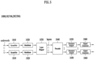
- FIG. 5 illustrates a signal processing circuit for a transmit signal.
- FIG. 7 is a diagram for explaining physical channels used in a 3GPP system and a general signal transmission method using them.
- LCC may be set as Primary CC (PCC) and UCC may be set as Secondary CC (SCC).
- PCC Primary CC
- SCC Secondary CC
- the base station may perform the following downlink channel access procedure (Channel Access Procedure; CAP) for the unlicensed band for downlink signal transmission in the unlicensed band.
- CAP downlink channel access procedure
- a base station may access multiple channels through which transmission is performed through one of the following Type A or Type B procedures.
- the counter N considered in the CAP is determined for each channel c i , and in this case, the counter for each channel is denoted by Nc;.
- a counter N considered in the CAP is determined for each channel c i , and a counter for each channel is denoted by Nc;.
- the base station may resume decrement of Nc i .
- the counter N for each channel c j ⁇ C may be determined according to the above-described descriptions, and in this case, the counter for each channel is denoted by Nc j .
- c j may mean a channel having the largest CW p value.
- Nc i Nc j .
- the base station When the base station ceases the transmission for any one of the channels to which Nc i is determined, the base station reinitialises Nc i for all channels.
- a channel c j ⁇ C may be selected by the base station as follows.
- the channel frequency of the channel set C selected by the gNB is a subset of one of the predefined channel frequency sets.
- step 2 of the procedure described above in section 3.1 above is modified as follows.
- the CW p value is maintained independently for each channel c;EC.
- any PDSCH that completely or partially overlaps the channel c i may be used.
- the CW p value of the channel c j1 ⁇ C is used.
- c j1 is the channel with the largest CW p among all channels in the set C.
- a UE and a base station scheduling or configuring UL transmission for the UE performs the following procedure for access to a channel (performing LAA Scell transmission(s)).
- LAA Scell transmission(s) performing LAA Scell transmission(s)
- an uplink CAP operation to which various embodiments of the present disclosure applicable will be described in detail on the assumption that Pcell, which is a licensed band, and Scell, which is one or more unlicensed bands are basically configured for the UE and the base station.
- the uplink CAP operation may be analogously applied to the case that only unlicensed band is configured for the UE and the base station.
- a UE may access according to a Type 1 or Type 2 UL channel access procedure on a channel on which UL transmission(s) is performed.
- Table 8 exemplifies that mp, minimum CW, maximum CW, Maximum Channel Occupancy Time (MCOT) and allowed CW sizes applied to the CAP vary according to the channel access priority classes.
- FIG. 14 is a diagram for explaining a UL CAP for unlicensed band transmission to which various embodiments of the present disclosure are applicable.
- the type 1 UL CAP of the UE for unlicensed band transmission to which various embodiments of the present disclosure are applicable may be summarized as follows.
- a transmitting node e.g., UE may initiate a channel access procedure (CAP) to operate in an unlicensed band (2110).
- CAP channel access procedure
- the UE may randomly select a backoff counter N within the contention window (CW) according to step 1.
- the value of N is set to the initial value Ninit (2120).
- Ninit is selected to be any value between 0 and CWp.
- step 4 the UE terminates the CAP process (2132).
- the UE may then perform a Tx burst transmission (2134).
- the backoff counter value is not 0 (2130; N)
- the UE decreases the backoff counter value by 1 according to step 2 (2140).
- the UE checks whether the channel is in an idle state (2150), and if the channel is in an idle state (2150; Y), checks whether the backoff counter value is 0 (2130).
- the UE checks whether the corresponding channel is in an idle state (2160) for a defer duration (Td; 25usec or more) longer than the slot time (e.g., 9usec) according to step 5. If the channel is in an idle state during the defer duration (2170; Y), the UE may resume the CAP process again.
- the UE senses the channel during the defer duration to determine whether it is in an idle state.
- the UE does not set the backoff counter value Ninit, but may perform the CAP process again from the backoff counter value 5 (or from 4 after decrementing the backoff counter value by 1).
- the UE re-performs operation 2160 to check again whether the channel is in an idle state during the new defer duration.
- the UE may transmit UL transmission on the channel if the following condition is satisfied
- the UE proceeds to step 1 after sensing the corresponding channel as idle during the slot durations of the defer duration Td.
- each slot duration Tsl is 9us
- Tf includes an idle slot duration Tsl at the starting point of Tf.
- the UE uses the Type 2A channel access procedure for UL transmission.
- T f includes a sensing slot at the starting point of the Tf. If two sensing slots in the T short_ul are sensed as idle, the channel is considered as idle during T short_ul .
- the UE uses the Type 2B channel access procedure for UL transmission.
- Tf includes sensing slots occurring within the last 9us of Tf. If the channel is sensed to be idle for at least 5us in total with at least 4us sensing occurring in the sensing slot, the channel is considered idle during Tf.
- FIG. 15 illustrates an example of a random access procedure.
- FIG. 15 illustrates a contention-based random access procedure.
- the RACH configuration regarding the initial bandwidth of the Primary Cell (Pcell) is included in the system information of the cell and provided to the UE.
- the RACH configuration includes information about a subcarrier spacing of a PRACH, available preambles, a preamble format, etc.
- the RACH configuration includes association information between SSBs and RACH (time-frequency) resources. The UE transmits a random access preamble in the RACH time-frequency resource associated with the detected or selected SSB.
- a threshold value of the SSB for RACH resource association may be configured by the network, and transmission or retransmission of the RACH preamble is performed based on the SSB in which the measured reference signal received power (RSRP) satisfies the threshold based on the SSB.
- the UE may select one of the SSB(s) that satisfies the threshold, and transmit or retransmit the RACH preamble based on the RACH resource associated with the selected SSB.
- the UE may reselect one of the SSB(s) and retransmit the RACH preamble based on the RACH resource associated with the reselected SSB. That is, the RACH resource for retransmission of the RACH preamble may be the same as and/or different from the RACH resource for transmitting the RACH preamble.
- Random access response information includes a preamble sequence transmitted by the UE, a temporary cell-RNTI (TC-RNTI) assigned by the base station to a UE that has attempted random access, and uplink transmission time alignment information, uplink transmission power adjustment information, and uplink radio resource allocation information.
- TC-RNTI temporary cell-RNTI
- the UE may know timing advance information for UL synchronization, an initial UL grant, and a TC-RNTI. The timing advance information is used to control uplink signal transmission timing.
- the network obtains timing advance information based on the timing information detected from the PRACH preamble received from the UE, and may send the corresponding timing advance information to the UE.
- the UE may transmit UL transmission on the uplink shared channel as Msg3 of the random access procedure based on the random access response information.
- Msg3 may include an RRC connection request and UE identifier.
- the network may send Msg4, which may be treated as a contention resolution message on DL. By receiving Msg4, the UE may enter the RRC connected state.
- the UL grant in the RAR schedules PUSCH transmission to the UE.
- the PUSCH carrying the initial UL transmission by the UL grant in the RAR is also referred to as Msg3 PUSCH.
- the content of the RAR UL grant starts at the MSB and ends at the LSB, and is given in Table 9.
- RAR UL grant field Number of bits
- Frequency hopping flag 1 Msg3 PUSCH frequency resource allocation 12
- TPC command is used to determine the transmit power of the Msg3 PUSCH, and is interpreted according to, for example, Table 10.
- Table 10 TPC command value [dB] 0 -6 1 -4 2 -2 3 0 4 2 5 4 6 6 7 8
- PUCCH (e,g,, PUCCH format 0/2) and PUSCH may be multiplexed in TDM or FDM scheme.
- Short PUCCH and long PUCCH from different UEs may be multiplexed in TDM or FDM scheme.
- Short PUCCHs in one slot from a single UE may be multiplexed in TDM scheme.
- a short PUCCH and a long PUCCH from in one slot a single UE may be multiplexed in TDM or FDM scheme.
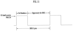
- up to 400 MHz per one carrier may be supported. If the UE operating on such a wideband carrier always operates with a radio frequency (RF) module for the entire carrier turned on, the UE battery consumption may increase.
- RF radio frequency
- different numerology e.g., subcarrier spacing
- the capability for the maximum bandwidth may be different for each UE.
- the base station may indicate the UE to operate only in a partial bandwidth rather than the entire bandwidth of the wideband carrier, and the partial bandwidth is referred to as a bandwidth part (BWP).
- BWP bandwidth part
- the UE fails LBT for the Msg A PUSCH after transmitting the Msg A PRACH preamble, the UE cannot transmit the Msg A PUSCH, and the base station that receives only the Msg A PRACH preamble and does not receive the Msg A PUSCH may indicate, through Msg B, a fall-back to Msg 3 is indicated, and the UE may switch to a 4-step RACH procedure.
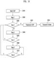
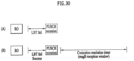
- FIG. 30 is a diagram illustrating an example of configuring a reception window of Msg B depending on success or failure of LBT for Msg A PUSCH transmission.
- FIG. 30(a) for a PO having a one-to-one correspondence with the RO related to the Msg A PRACH preamble transmitted by the UE, when LBT for Msg A PUSCH transmission fails, the UE does not transmit Msg A PUSCH and does not configure a window or timer for receiving Msg B. Meanwhile, in FIG.
- the UE If the UE does not identify its RAPID and UE-ID through Msg B, the UE continues to perform blind decoding until the reception window or timer of Msg B expires.
- the UE may perform the resource selection procedure for random access up to the specified maximum number of transmissions after a certain back-off time, and then the Radio Link Failure procedure may be performed.
- the UE may perform a resource selection procedure for a random access after a back-off time and a Radio Link Failure (RLF) procedure.
- RLF Radio Link Failure
- the UE that fails to transmit the Msg A PUSCH expects a fallback RAR that matches its RAPID during the window or timer duration as described above, and even if it detects a success RAR including its own RAPID it may ignore the same.
- a UE that fails to receive the RAR by the time the window or timer expires may perform a resource selection procedure for random access after a certain back-off time and a Radio Link Failure procedure.
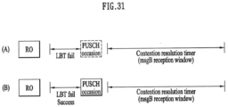
- the UE transmits the Msg A PUSCH if the LBT for the Msg A PUSCH transmission is successful, and configures a window or timer for receiving Msg B.
- the window or timer configured for receiving Msg B in FIG. 31(a) or 31(b) starts from the first symbol of a resource for monitoring Msg B, and the corresponding start time may be a time point after at least one symbol from the last symbol of PUSCH Occasion.
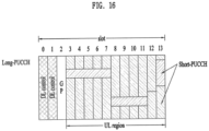
- a RACH Occasion (RO) in which the Msg A PRACH preamble is transmitted may be mapped with a plurality of PUSCH Occasions (POs) in which the Msg A PUSCH is transmitted.
- the plurality of Msg A PUSCH Occasions may be continuously allocated without a time gap between Msg A PUSCH Occasions in the form of Time Division Multiplexing (TDM).
- TDM Time Division Multiplexing
- the plurality of Msg A PUSCH Occasions may be allocated with a constant time gap.
- the one to multiple mapping relationship between RACH Occasion and Msg A PUSCH Occasions may be configured according to various schemes. As a simple example, preambles for all 2-step RACH procedures may be mapped to all of a plurality of Msg A PUSCH Occasions, respectively.
- preambles for the 2-step RACH procedure may be divided into N subsets, and the number of Msg A PUSCH Occasions mapped to the preamble may be configured differently for each subset. That is, with respect to preambles divided into N subsets, 1) in the case of a subset including preambles corresponding to #0 to #A-1, each preamble may be mapped to one Msg A PUSCH Occasion to form one to one mapping relationship, and 2) in the case of a subset including preambles corresponding to #A to #B-1, each preamble may be mapped to two Msg A PUSCH Occasions to form one to two mapping relationship, In addition to this, 3) in the case of a subset including the preambles corresponding to #B to #C-1, each preamble may be mapped to three Msg A PUSCH Occasions to form one to three mapping relationship, and further settings for mapping relationships are also possible.
- the preambles included in the subset of 1) have a one-to-one mapping relationship with Msg A PUSCH Occasions, thus one PUSCH Occasion corresponding to the transmitted PRACH preamble is configured, whether to transmit Msg A PUSCH depending on success or failure of LBT is determined for the corresponding one PUSCH Occasion.
- the preambles included in the subset of 2) have a one to two mapping relationship with Msg A PUSCH Occasions, thus two PUSCH Occasions corresponding to the transmitted PRACH preamble are configured, whether to transmit Msg A PUSCH depending on success or failure of LBT is determined for the corresponding two PUSCH Occasions.
- preambles included in the subset of 3) have a one to three mapping relationship with Msg A PUSCH Occasions, thus three PUSCH Occasions corresponding to the transmitted PRACH preamble are configured, whether to transmit Msg A PUSCH depending on success or failure of LBT is determined for the corresponding three PUSCH Occasions.
- the UE may select a subset according to a reference signal received power (RSRP) for the reference signals such as a received Synchronization Signal Block (SSB) or a Channel State Information-Reference Signal (CSI-RS) or may select a subset according to a priority criterion such as the size of the Msg A PUSCH to be transmitted. Based on the selected subset, the UE may perform LBT for PUSCH Occasion(s) corresponding to the preamble included in the subset, attempt to transmit Msg A PUSCH, and configure a window or timer for receiving Msg B.
- RSRP reference signal received power
- SSB Synchronization Signal Block
- CSI-RS Channel State Information-Reference Signal
- Msg A PUSCH may be transmitted according to Example 1 or Example 2 described above, and a window or timer for receiving Msg B may be configured.
- a window or timer for receiving Msg B may be configured.
- the modulo operation is (UE-ID)mod(M), and each preamble is sequentially mapped to a PUSCH Occasion according to the result value of (UE-ID)mod(M) based on the UE-ID included in each preamble, the UE may transmit the Msg A PUSCH based on the mapped Msg A PUSCH Occasion.
- a window or timer for receiving Msg B may be started after the mapped one PUSCH Occasion.
- the UE may transmit Msg A PUSCH in all Msg A PUSCH Occasions corresponding to the preamble.
- the UE attempts to transmit Msg A PUSCH in a plurality of PUSCH Occasions corresponding to the preamble, and LBT is performed on all of the plurality of PUSCH Occasions in the NR-U system. Therefore, it is necessary to configure which PUSCH Occasions will be a basis for starting a window or timer for receiving Msg B among a plurality of PUSCH Occasions, and therefor, the following examples may be utilized.
- Example 1 and Example 2 even though the UE succeeds in the LBT, or regardless of the success or failure of the LBT, in case that situation such as a deterioration in the channel status of said one PUSCH Occasion occur, the UE may predict the detection error probability for the Msg A PUSCH for itself and may transmit only the Msg A PRACH preamble and does not transmit the Msg A PUSCH. That is, among the following examples, those examples that may be utilized regardless of success or failure of LBT are not limited to be applied to the NR-U system and may be applicable to a licensed carrier.
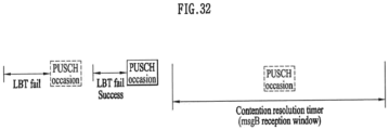
- Example 3 is a method for the UE to perform LBT on each of a plurality of PUSCH Occasions, a window or timer for receiving Msg B is configured based on a PUSCH Occasion that has succeeded in LBT.
- Example 3 is the same as example 1 in that a window or timer for receiving Msg B is configured based on PUSCH Occasion that has succeeded in LBT.
- a window or timer for receiving Msg B is not configured. That is, when the UE fails to transmit Msg A PUSCH, a window or timer for receiving Msg B does not start.
- Example 3 if LBT for a specific PUSCH Occasion succeeds, Msg A PUSCH transmission in the corresponding PUSCH Occasion is normally performed, and a window or timer for receiving Msg B may also be started.
- the start time of the window or timer for receiving Msg B may be after at least one symbol from the last symbol of the PUSCH Occasion corresponding to the Msg A PRACH preamble transmitted by the UE.
- a window or timer for receiving Msg B may be configured to start with an interval of at least one symbol from PUSCH Occasion in symbol units.
- the start time of the window or timer may be the first symbol of the resource for monitoring Msg B.
- the resource for monitoring Msg B may be a resource corresponding to the earliest CORESET of the Type1-PDCCH Common Search Space set for the UE to receive the PDCCH for Msg B.
- the window or timer configured to receive the Msg B may start from the first symbol of the resource for monitoring the Msg B, and the corresponding start time may be a time point after at least one symbol from the last symbol of Msg A PUSCH Occasion.
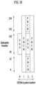
- FIG. 32 is a diagram illustrating an example of configuring a window for receiving Msg B according to a PUSCH Occasion that has succeeded in LBT among a plurality of PUSCH Occasions.
- the UE does not configure the window or timer for receiving Msg B based on the specific PO.
- the UE performs LBT until a PO in which LBT succeeds comes out, transmits Msg A PUSCH in the PO where LBT succeeds, and a window or timer for receiving Msg B may be configured at a time point after at least one symbol from the last symbol of the corresponding PO.
- the POs shown in FIG. 32 correspond to one Msg A PRACH preamble in one to multiple scheme, and may be resources allocated redundantly in the form of TDM.
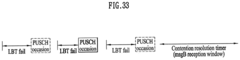
- Example 4 is a method, for a plurality of PUSCH Occasions corresponding to the Msg A PRACH preamble, that a window or timer for receiving Msg B is always configured based on the last PUSCH Occasion among the plurality of PUSCH Occasions, regardless of success or failure of LBT for each PUSCH Occasion That is, in order to prepare for the failure of the LBT for all of the corresponding plurality of PUSCH Occasions and to expect the reception of the fallback RAR, a window or timer for receiving Msg B is always configured to start after at least one symbol from the last symbol of the last PUSCH Occasion among the plurality of TDMed PUSCH Occasions.
- the method of Example 4 is a method applicable without distinction of a licensed carrier or an unlicensed carrier, and operations of a UE and a base station related to Example 4 may be the same as those described in Example 2.
- Example 4 if LBT for a specific Msg A PUSCH Occasion succeeds, Msg A PUSCH transmission in the corresponding Msg A PUSCH Occasion is normally performed, and the reception window or timer of Msg B may also be started based on the Msg A PUSCH Occasion where LBT is successful.
- the UE transmitting the Msg A PUSCH may expect to receive a success RAR, and may expect to successfully complete the 2-step RACH procedure.
- a window or a timer for receiving the Msg B is configured based on the last Msg A PUSCH Occasion. If the UE fails to transmit the Msg A PUSCH even in the last Msg A PUSCH Occasion, the UE may expect to receive a fallback RAR, and may expect to transmit Msg 3 by falling back to the 4-step RACH procedure.
- the time point at which the window or timer for receiving Msg B starts may be after at least one symbol from the last symbol of the corresponding last Msg A PUSCH Occasion, as described above.
- a window or timer for receiving Msg B may be configured to start with an interval of at least one symbol from Msg A PUSCH Occasion in symbol units.
- the start time of a window or timer may be the first symbol of a resource for monitoring Msg B.
- the resource for monitoring Msg B may be a resource corresponding to the earliest CORESET of the Type 1 -PDCCH Common Search Space set for the UE to receive the PDCCH for Msg B.
- FIG. 33 is a diagram illustrating an example of configuring a window for receiving Msg B according to the last Msg A PUSCH Occasion, regardless of success or failure of LBT among a plurality of Msg A PUSCH Occasions.
- a window or timer for receiving Msg B may be configured based on the last PO.
- the UE may configure a window or timer for receiving Msg B at a time point after at least symbol from the last symbol of the corresponding last PO.
- the POs shown in FIG. 33 correspond to one Msg A PRACH preamble in one to multiple scheme, and may be resources allocated redundantly in the form of TDM.
- Example 5 for a plurality of Msg A PUSCH Occasions corresponding to the Msg A PRACH preamble, regardless of success or failure of LBT for each Msg A PUSCH Occasion, a window or a timer for receiving Msg B is always set based on the first Msg A PUSCH Occasion among the plurality of Msg A PUSCH Occasions. That is, a window or a timer start time for receiving Msg B is set after at least one symbol from the last symbol of the first Msg A PUSCH Occasion among a plurality of TDMed Msg A PUSCH Occasions.
- the operation of the UE and the base station after the reception window or timer for Msg B based on the first Msg A PUSCH Occasion according to Example 5 is started may be the same as that described in Example 2, and at the same time, the UE may perform LBT for several remaining Msg A PUSCH Occasions thereafter.
- the UE configures the window or timer for receiving Msg B after the first Msg A PUSCH Occasion and expects to receive Msg B, and at the same time performs LBT for subsequent Msg A PUSCH Occasions, so that, depending on which Msg A PUSCH Occasion the UE successfully transmits Msg A PUSCH, the reception time of Msg B may be before or after the transmission time of Msg A PUSCH. For example, if the UE succeeds in LBT for the first PUSCH Occasion and transmits the Msg A PUSCH through the first Msg A PUSCH Occasion, the reception time of the Msg B may be after the transmission time of the Msg A PUSCH.
- the reception time of Msg B is before the transmission time of the Msg A PUSCH.
- the subsequent operation of the UE performing LBT for a plurality of Msg A PUSCH Occasions may vary as follows depending whether the UE performing LBT finally succeeds in LBT but receives Msg B at a time before transmitting Msg A PUSCH, or whether Msg B is received at a time point after PUSCH transmission.
- a target object that each UE expect to receive such as a success RAR or a fallback RAR signal, may be different.
- the problem of duplicate transmission for the success RAR or the fallback RAR may also be solved by applying a method similar to the method of the Example 2.
- the base station receives the Msg A PRACH preamble and fails to receive the Msg A PUSCH, and therefore, the Msg B transmitted by the base station includes fallback RAR including containing information about a fallback and Msg 3 transmission.
- the UE stores the fallback RAR and performs LBT on the remaining Msg A PUSCH Occasions to expect transmission of the Msg A PUSCH.
- transmission information such as a grant for Msg 3 transmitted through the fallback RAR of Msg B may indicate subsequent resources in consideration of the fact that the base station initially allocates a plurality of Msg A PUSCH Occasions.
- the UE receives Msg B from the base station after succeeding in LBT and transmitting the Msg A PUSCH, the subsequent operation of the UE varies according to the contents of the Msg B transmitted by the base station. From the UE's point of view, since Msg A PUSCH has already been transmitted, if Msg B includes a fallback RAR, it may be ignored and reception of a success RAR may be expected. If the success RAR is not received during the reception window or the timer period of Msg B, the UE may fall back to the 4-step RACH procedure based on the previously received fallback RAR and transmit Msg 3.
- the UE may perform a resource selection procedure for random access after a set back-off time in order to avoid a collision with the redundantly transmitted RAPID.
- the UE may recognize an operation after the configured window or timer for receiving Msg B has expired as an operation according to the unsuccessful contention resolution.
- the UE may select a 2-step RACH procedure or a 4-step RACH procedure again according to a channel state after a preconfigured back-off time, and perform a resource selection procedure for random access.
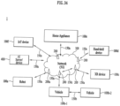
- FIG. 34 shows an example of a wireless communication environment to which embodiments of the present disclosure may be applied.
- the communication system 1 applied to the present disclosure includes a wireless device, a base station, and a network.
- the wireless device means a device that performs communication using a wireless access technology (e.g., 5G NR (New RAT), LTE (Long Term Evolution)), and may be referred to as a communication/wireless/5G device.
- a wireless access technology e.g., 5G NR (New RAT), LTE (Long Term Evolution)
- the wireless device includes a robot 100a, a vehicle 100b-1, 100b-2, an extended Reality (XR) device 100c, a hand-held device 100d, and a home appliance 100e, an Internet of Thing (IoT) device 100f, and an AI device/server 400.
- XR extended Reality
- IoT Internet of Thing
- the vehicle may include a vehicle equipped with a wireless communication function, an autonomous driving vehicle, a vehicle capable of performing inter-vehicle communication, and the like.
- the vehicle may include an Unmanned Aerial Vehicle (UAV) (e.g., a drone).
- UAV Unmanned Aerial Vehicle
- XR devices include AR (Augmented Reality)/VR (Virtual Reality)/MR (Mixed Reality) devices, and may be implemented in the form of a Head-Mounted Device (HMD), a Head-Up Display (HUD) provided in a vehicle, a television, a smartphone, a computer, a wearable device, a home appliance, a digital signage, a vehicle, a robot, and the like.
- HMD Head-Mounted Device
- HUD Head-Up Display
- the portable device may include a smart phone, a smart pad, a wearable device (e.g., a smart watch, smart glasses), a computer (e.g., a laptop computer), and the like.
- Home appliances may include a TV, a refrigerator, a washing machine, and the like.
- the IoT device may include a sensor, a smart meter, and the like.
- the base station and the network may be implemented as a wireless device, and the specific wireless device 200a may operate as a base station/network node to other wireless devices.
- the wireless devices 100a to 100f may be connected to the network 300 through the base station 200. Artificial intelligence (AI) technology may be applied to the wireless devices 100a to 100f, and the wireless devices 100a to 100f may be connected to the AI server 400 through the network 300.
- the network 300 may be configured using a 3G network, a 4G (e.g., LTE) network, or a 5G (e.g., NR) network.
- the wireless devices 100a to 100f may communicate with each other through the base station 200/network 300, but may also communicate directly (e.g., sidelink communication) without passing through the base station/network.
- Wireless communication/connection 150a, 150b, 150c may be performed between the wireless devices 100a to 100f and the base station 200 and between the base station 200 and the base station 200.
- wireless communication/connection may be made through various wireless access technologies (e.g., 5G NR) such as uplink/downlink communication 150a, sidelink communication 150b (or D2D communication), and inter-base station communication 150c.
- 5G NR wireless access technologies
- the wireless device and the base station/wireless device, and the base station and the base station may transmit/receive radio signals to each other.
- the wireless communication/connection 150a, 150b, and 150c may transmit/receive signals through various physical channels.
- various signal processing processes e.g., channel encoding/decoding, modulation/demodulation, resource mapping/demapping, etc.
- resource allocation processes etc.
- a specific operation described to be performed by a base station in the present disclosure may be performed by an upper node thereof in some cases. That is, it is clear that various operations performed for communication with the terminal in a network including a plurality of network nodes including the base station may be performed by the base station or other network nodes other than the base station.
- the base station may be replaced by terms such as a fixed station, gNode B (gNB), Node B, eNode B (eNB), an access point, etc.
- a method for receiving a downlink signal by a terminal based on a random access procedure in the unlicensed band as described above and an apparatus for the same have been mainly described with examples applied to the 5th generation NewRAT system, but may be applied to various wireless communication systems other than the 5th generation NewRAT system.
Landscapes
- Engineering & Computer Science (AREA)
- Computer Networks & Wireless Communication (AREA)
- Signal Processing (AREA)
- Mobile Radio Communication Systems (AREA)
Claims (11)
- Verfahren zum Empfangen eines Downlinksignals auf der Grundlage eines Zufallszugriffsverfahrens durch ein Endgerät, wobei das Verfahren umfasst:Übertragen nur einer physikalischen Zufallszugriffskanal-, PRACH-, Präambel durch eine Nachricht A an eine Basisstation, ohne sowohl den PRACH als auch einen physikalischen gemeinsam genutzten Uplinkkanal, PUSCH, in der Nachricht A zu übertragen;Empfangen einer Zufallszugriffsantwort, RAR, durch eine Nachricht B von der Basisstation als Antwort auf die Nachricht A;Empfangen von Informationen über mindestens einen diskontinuierlichen Empfangs-, DRX-, Zeitgeber zur Konfiguration des DRX-Betriebs von der Basisstation; undEmpfangen eines Downlinksignals während einer Einschaltdauer basierend auf dem mindestens einen DRX-Zeitgeber von der Basisstation,wobei die PRACH-Präambel auf eine PUSCH-Gelegenheit für die Nachricht A abgebildet wird,wobei für die Übertragung nur der PRACH-Präambel ein Fenster zum Erfassen der Nachricht B mindestens ein Symbol nach einem letzten Symbol der PUSCH-Gelegenheit beginnt, die der PRACH-Präambel-Übertragung entspricht.
- Verfahren nach Anspruch 1,
wobei die RAR eine Fallback-RAR ist und die Fallback-RAR Uplink-, UL-, Erteilungsinformationen enthält. - Verfahren nach Anspruch 2,wobei ein PUSCH, der durch die in der Fallback-RAR enthaltenen UL-Erteilungsinformationen geplant ist, übertragen wird, undwobei ein PDSCH für eine Konfliktauflösung empfangen wird.
- Verfahren nach Anspruch 1,
wobei das Fenster bei einem ersten Symbol einer Ressource beginnt, die sich auf ein Überwachen der Nachricht B bezieht. - Verfahren nach Anspruch 1,
wobei die PUSCH-Gelegenheit eine gültige PUSCH-Gelegenheit ist, die sich auf eine PRACH-Gelegenheit für die PRACH-Präambel bezieht. - Vorrichtung zum Empfangen eines Downlinksignals auf der Grundlage eines Zufallszugriffsverfahrens, wobei die Vorrichtung umfasst:mindestens einen Prozessor; undmindestens einen Speicher, der betriebsfähig mit dem mindestens einen Prozessor verbunden ist und Befehle speichert, die, basierend auf der Ausführung durch den mindestens einen Prozessor, spezifische Operationen durchführen,wobei die spezifischen Operationen umfassen:Übertragen nur einer physikalischen Zufallszugriffskanal-, PRACH-, Präambel durch eine Nachricht A, ohne sowohl den PRACH als auch einen physikalischen gemeinsam genutzten Uplinkkanal, PUSCH, in der Nachricht A zu übertragen;Empfangen einer Zufallszugriffsantwort, RAR, durch eine Nachricht B als Antwort auf die Nachricht A;Empfangen von Informationen über mindestens einen diskontinuierlichen Empfangs-, DRX-, Zeitgeber zur Konfiguration eines DRX-Betriebs; undEmpfangen eines Downlinksignals während einer Einschaltdauer basierend auf dem mindestens einen DRX-Zeitgeber,wobei die PRACH-Präambel auf eine PUSCH-Gelegenheit für die Nachricht A abgebildet wird,wobei für die Übertragung nur der PRACH-Präambel ein Fenster zum Erfassen der Nachricht B mindestens ein Symbol nach einem letzten Symbol der PUSCH-Gelegenheit beginnt, die der PRACH-Präambel-Übertragung entspricht.
- Vorrichtung nach Anspruch 6,
wobei die RAR eine Fallback-RAR ist und die Fallback-RAR Uplink-, UL-, Erteilungsinformationen enthält. - Verfahren nach Anspruch 7,wobei ein PUSCH, der durch die in der Fallback-RAR enthaltenen UL-Erteilungsinformationen geplant ist, übertragen wird, undwobei ein PDSCH für eine Konfliktauflösung empfangen wird.
- Vorrichtung nach Anspruch 6,
wobei das Fenster bei einem ersten Symbol einer Ressource beginnt, die sich auf ein Überwachen der Nachricht B bezieht. - Vorrichtung nach Anspruch 6,
wobei die PUSCH-Gelegenheit eine gültige PUSCH-Gelegenheit ist, die sich auf eine PRACH-Gelegenheit für die erste PRACH-Präambel bezieht. - Endgerät zum Empfangen eines Downlinksignals auf der Grundlage eines Zufallszugriffsverfahrens, wobei das Endgerät umfasst:mindestens einen Transceiver;mindestens einen Prozessor; undmindestens einen Speicher, der betriebsfähig mit dem mindestens einen Prozessor verbunden ist und Befehle speichert, die, basierend auf der Ausführung durch den mindestens einen Prozessor, spezifische Operationen durchführen,wobei die spezifischen Operationen umfassen:Übertragen nur einer physikalischen Zufallszugriffskanal-, PRACH-, Präambel durch eine Nachricht A an eine Basisstation, ohne sowohl den PRACH als auch einen physikalischen gemeinsam genutzten Uplinkkanal, PUSCH, in der Nachricht A zu übertragen;Empfangen einer Zufallszugriffsantwort, RAR, durch eine Nachricht B von der Basisstation als Antwort auf die Nachricht A;Empfangen von Informationen über mindestens einen diskontinuierlichen Empfangs-, DRX-, Zeitgeber zur Konfiguration des DRX-Betriebs von der Basisstation; undEmpfangen eines Downlinksignals während einer Einschaltdauer basierend auf dem mindestens einen DRX-Zeitgeber von der Basisstation,wobei die PRACH-Präambel eine PRACH-Präambel ist, die auf eine PUSCH-Gelegenheit für die Nachricht A abgebildet wird,wobei für die Übertragung nur der PRACH-Präambel ein Fenster zum Erfassen der Nachricht B mindestens ein Symbol nach einem letzten Symbol der PUSCH-Gelegenheit beginnt, die der PRACH-Präambel-Übertragung entspricht.
Applications Claiming Priority (2)
| Application Number | Priority Date | Filing Date | Title |
|---|---|---|---|
| KR20190123340 | 2019-10-04 | ||
| PCT/KR2020/006585 WO2021066276A1 (ko) | 2019-10-04 | 2020-05-20 | 비면허 대역에서 단말이 임의 접속 과정에 기반하여 하향링크 신호를 수신하는 방법 및 이를 위한 장치 |
Publications (3)
| Publication Number | Publication Date |
|---|---|
| EP4040908A1 EP4040908A1 (de) | 2022-08-10 |
| EP4040908A4 EP4040908A4 (de) | 2022-11-23 |
| EP4040908B1 true EP4040908B1 (de) | 2024-07-03 |
Family
ID=75338177
Family Applications (1)
| Application Number | Title | Priority Date | Filing Date |
|---|---|---|---|
| EP20873139.8A Active EP4040908B1 (de) | 2019-10-04 | 2020-05-20 | Verfahren zum empfangen eines downlink-signals durch ein endgerät auf der basis eines zufallszugriffskanalverfahrens, und gerät dafür |
Country Status (6)
| Country | Link |
|---|---|
| US (2) | US11683844B2 (de) |
| EP (1) | EP4040908B1 (de) |
| JP (2) | JP7389899B2 (de) |
| KR (1) | KR20220076451A (de) |
| CN (1) | CN114467350B (de) |
| WO (1) | WO2021066276A1 (de) |
Families Citing this family (6)
| Publication number | Priority date | Publication date | Assignee | Title |
|---|---|---|---|---|
| WO2021046828A1 (zh) * | 2019-09-12 | 2021-03-18 | 北京小米移动软件有限公司 | 随机接入方法及装置 |
| CN115486168A (zh) * | 2020-05-13 | 2022-12-16 | Oppo广东移动通信有限公司 | 资源配置方法与装置、终端设备和网络设备 |
| US12200754B2 (en) * | 2021-10-22 | 2025-01-14 | Qualcomm Incorporated | Techniques for assisted message decoding |
| CN116261203B (zh) * | 2023-03-24 | 2025-06-24 | 鹏城实验室 | 免授权信号接入方法、系统、终端及存储介质 |
| US20240373503A1 (en) * | 2023-05-05 | 2024-11-07 | Qualcomm Incorporated | Early cell discontinuous transmission and/or discontinuous reception signaling |
| US20240430938A1 (en) * | 2023-06-20 | 2024-12-26 | Qualcomm Incorporated | Random access channel occasion selection |
Family Cites Families (15)
| Publication number | Priority date | Publication date | Assignee | Title |
|---|---|---|---|---|
| KR100968020B1 (ko) * | 2008-06-18 | 2010-07-08 | 엘지전자 주식회사 | 랜덤 액세스 절차를 수행하는 방법 및 그 단말 |
| CN101835273B (zh) * | 2009-03-13 | 2015-06-03 | 中兴通讯股份有限公司 | 随机接入方法以及终端 |
| ES2963270T3 (es) * | 2012-02-06 | 2024-03-26 | Samsung Electronics Co Ltd | Procedimiento y aparato para transmitir/recibir datos en múltiples portadoras en un sistema de comunicación móvil |
| WO2014209040A1 (ko) * | 2013-06-26 | 2014-12-31 | 엘지전자 주식회사 | 무선 자원의 용도 변경을 지원하는 무선 통신 시스템에서 불연속 수신 지원 방법 및 이를 위한 장치 |
| US10051504B2 (en) * | 2016-02-01 | 2018-08-14 | Telefonaktiebolaget Lm Ericsson (Publ) | Methods and apparatuses for supporting MDT during eDRX |
| US10327265B2 (en) * | 2016-11-04 | 2019-06-18 | Qualcomm Incorporated | Random access procedure timing designs |
| US11134422B2 (en) | 2017-02-28 | 2021-09-28 | Guangdong Oppo Mobile Telecommunications Corp., Ltd. | Random access method, terminal device and network device |
| US10555338B2 (en) * | 2017-08-11 | 2020-02-04 | Mediatek Inc. | NR-PRACH multiple Msg1 transmission |
| US20200221503A1 (en) | 2017-09-28 | 2020-07-09 | Sony Corporation | Terminal device, base station device, method, and recording medium |
| US10945290B2 (en) * | 2018-02-15 | 2021-03-09 | Comcast Cable Communications, Llc | Random access using supplemental uplink |
| AR114402A1 (es) * | 2018-03-02 | 2020-09-02 | Ericsson Telefon Ab L M | Asignación de recursos del dominio de tiempo para la transmisión por el canal físico compartido de enlace ascendente |
| US11653387B2 (en) * | 2018-09-28 | 2023-05-16 | Samsung Electronics Co., Ltd. | Random access method and apparatus in wireless communication system |
| CN111263452B (zh) * | 2019-02-01 | 2023-06-30 | 维沃移动通信有限公司 | 信息传输的方法和终端设备 |
| US11395343B2 (en) * | 2019-02-14 | 2022-07-19 | Sierra Wireless, Inc. | Method and apparatus for supporting two-step random access channel usage in a wireless communication system |
| US11985706B2 (en) * | 2019-03-28 | 2024-05-14 | Comcast Cable Communications, Llc | Access procedures for wireless communications |
-
2020
- 2020-05-20 EP EP20873139.8A patent/EP4040908B1/de active Active
- 2020-05-20 WO PCT/KR2020/006585 patent/WO2021066276A1/ko not_active Ceased
- 2020-05-20 CN CN202080068697.XA patent/CN114467350B/zh active Active
- 2020-05-20 JP JP2022520419A patent/JP7389899B2/ja active Active
- 2020-05-20 KR KR1020227007197A patent/KR20220076451A/ko not_active Ceased
-
2022
- 2022-03-09 US US17/690,707 patent/US11683844B2/en active Active
-
2023
- 2023-04-20 US US18/304,002 patent/US12127266B2/en active Active
- 2023-11-14 JP JP2023193419A patent/JP2024012585A/ja active Pending
Non-Patent Citations (1)
| Title |
|---|
| SAMSUNG: "2 Step RA: Fallback from 2 Step to 4 Step RACH", vol. RAN WG2, no. Prague, Czech Republic; 20190826 - 20190830, 15 August 2019 (2019-08-15), XP051766633, Retrieved from the Internet <URL:http://www.3gpp.org/ftp/tsg_ran/WG2_RL2/TSGR2_107/Docs/R2-1908811.zip> [retrieved on 20190815] * |
Also Published As
| Publication number | Publication date |
|---|---|
| JP7389899B2 (ja) | 2023-11-30 |
| US11683844B2 (en) | 2023-06-20 |
| JP2022551085A (ja) | 2022-12-07 |
| US20220201763A1 (en) | 2022-06-23 |
| CN114467350A (zh) | 2022-05-10 |
| WO2021066276A1 (ko) | 2021-04-08 |
| US20230254906A1 (en) | 2023-08-10 |
| KR20220076451A (ko) | 2022-06-08 |
| EP4040908A1 (de) | 2022-08-10 |
| CN114467350B (zh) | 2025-09-05 |
| EP4040908A4 (de) | 2022-11-23 |
| JP2024012585A (ja) | 2024-01-30 |
| US12127266B2 (en) | 2024-10-22 |
Similar Documents
| Publication | Publication Date | Title |
|---|---|---|
| EP4040905B1 (de) | Verfahren zur durchführung von direktzugriffskanalverfahren durch ein endgerät in einem unlizenzierten band und vorrichtung dafür | |
| US12302402B2 (en) | Method for transmitting and receiving signal for terminal to perform random access channel procedure in unlicensed band, and apparatus therefor | |
| US12127263B2 (en) | Method and apparatus for transmitting and receiving signal for RACH procedure by UE in wireless communication system | |
| EP4040908B1 (de) | Verfahren zum empfangen eines downlink-signals durch ein endgerät auf der basis eines zufallszugriffskanalverfahrens, und gerät dafür | |
| KR102557584B1 (ko) | 비면허 대역에서 임의 접속 과정을 수행하기 위한 신호를 송수신하는 방법 및 이를 위한 장치 | |
| US12349208B2 (en) | Method whereby terminal transmits and receives signals for carrying out random access channel procedure in wireless communication system, and device therefor | |
| US12041662B2 (en) | Method for terminal to perform random access channel procedure in wireless communication system, and device for same | |
| US11864236B2 (en) | Method and apparatus for performing RACH procedure by UE in wireless communication system | |
| US11778671B2 (en) | Method for performing random-access channel procedure by terminal in wireless communication system, and device therefor | |
| US20220210751A1 (en) | Method whereby terminal carries out random access channel procedure in wireless communication system, and device therefor |
Legal Events
| Date | Code | Title | Description |
|---|---|---|---|
| STAA | Information on the status of an ep patent application or granted ep patent |
Free format text: STATUS: THE INTERNATIONAL PUBLICATION HAS BEEN MADE |
|
| PUAI | Public reference made under article 153(3) epc to a published international application that has entered the european phase |
Free format text: ORIGINAL CODE: 0009012 |
|
| STAA | Information on the status of an ep patent application or granted ep patent |
Free format text: STATUS: REQUEST FOR EXAMINATION WAS MADE |
|
| 17P | Request for examination filed |
Effective date: 20220429 |
|
| AK | Designated contracting states |
Kind code of ref document: A1 Designated state(s): AL AT BE BG CH CY CZ DE DK EE ES FI FR GB GR HR HU IE IS IT LI LT LU LV MC MK MT NL NO PL PT RO RS SE SI SK SM TR |
|
| A4 | Supplementary search report drawn up and despatched |
Effective date: 20221024 |
|
| RIC1 | Information provided on ipc code assigned before grant |
Ipc: H04L 1/00 20060101ALI20221018BHEP Ipc: H04W 52/02 20090101ALI20221018BHEP Ipc: H04W 72/14 20090101ALI20221018BHEP Ipc: H04W 72/12 20090101ALI20221018BHEP Ipc: H04W 74/00 20090101ALI20221018BHEP Ipc: H04W 74/08 20090101AFI20221018BHEP |
|
| DAV | Request for validation of the european patent (deleted) | ||
| DAX | Request for extension of the european patent (deleted) | ||
| RAP3 | Party data changed (applicant data changed or rights of an application transferred) |
Owner name: LG ELECTRONICS INC. |
|
| STAA | Information on the status of an ep patent application or granted ep patent |
Free format text: STATUS: EXAMINATION IS IN PROGRESS |
|
| 17Q | First examination report despatched |
Effective date: 20230713 |
|
| GRAP | Despatch of communication of intention to grant a patent |
Free format text: ORIGINAL CODE: EPIDOSNIGR1 |
|
| STAA | Information on the status of an ep patent application or granted ep patent |
Free format text: STATUS: GRANT OF PATENT IS INTENDED |
|
| RIC1 | Information provided on ipc code assigned before grant |
Ipc: H04W 76/28 20180101ALN20231214BHEP Ipc: H04W 16/14 20090101ALN20231214BHEP Ipc: H04L 1/00 20060101ALI20231214BHEP Ipc: H04W 52/02 20090101ALI20231214BHEP Ipc: H04W 72/12 20090101ALI20231214BHEP Ipc: H04W 74/00 20090101ALI20231214BHEP Ipc: H04W 74/08 20090101AFI20231214BHEP |
|
| INTG | Intention to grant announced |
Effective date: 20240105 |
|
| RIC1 | Information provided on ipc code assigned before grant |
Ipc: H04W 76/28 20180101ALN20231215BHEP Ipc: H04W 16/14 20090101ALN20231215BHEP Ipc: H04L 1/00 20060101ALI20231215BHEP Ipc: H04W 52/02 20090101ALI20231215BHEP Ipc: H04W 72/12 20090101ALI20231215BHEP Ipc: H04W 74/00 20090101ALI20231215BHEP Ipc: H04W 74/08 20090101AFI20231215BHEP |
|
| GRAS | Grant fee paid |
Free format text: ORIGINAL CODE: EPIDOSNIGR3 |
|
| GRAA | (expected) grant |
Free format text: ORIGINAL CODE: 0009210 |
|
| STAA | Information on the status of an ep patent application or granted ep patent |
Free format text: STATUS: THE PATENT HAS BEEN GRANTED |
|
| AK | Designated contracting states |
Kind code of ref document: B1 Designated state(s): AL AT BE BG CH CY CZ DE DK EE ES FI FR GB GR HR HU IE IS IT LI LT LU LV MC MK MT NL NO PL PT RO RS SE SI SK SM TR |
|
| REG | Reference to a national code |
Ref country code: CH Ref legal event code: EP |
|
| REG | Reference to a national code |
Ref country code: DE Ref legal event code: R096 Ref document number: 602020033536 Country of ref document: DE |
|
| REG | Reference to a national code |
Ref country code: LT Ref legal event code: MG9D |
|
| REG | Reference to a national code |
Ref country code: NL Ref legal event code: MP Effective date: 20240703 |
|
| PG25 | Lapsed in a contracting state [announced via postgrant information from national office to epo] |
Ref country code: PT Free format text: LAPSE BECAUSE OF FAILURE TO SUBMIT A TRANSLATION OF THE DESCRIPTION OR TO PAY THE FEE WITHIN THE PRESCRIBED TIME-LIMIT Effective date: 20241104 |
|
| REG | Reference to a national code |
Ref country code: AT Ref legal event code: MK05 Ref document number: 1701090 Country of ref document: AT Kind code of ref document: T Effective date: 20240703 |
|
| PG25 | Lapsed in a contracting state [announced via postgrant information from national office to epo] |
Ref country code: NL Free format text: LAPSE BECAUSE OF FAILURE TO SUBMIT A TRANSLATION OF THE DESCRIPTION OR TO PAY THE FEE WITHIN THE PRESCRIBED TIME-LIMIT Effective date: 20240703 |
|
| PG25 | Lapsed in a contracting state [announced via postgrant information from national office to epo] |
Ref country code: PT Free format text: LAPSE BECAUSE OF FAILURE TO SUBMIT A TRANSLATION OF THE DESCRIPTION OR TO PAY THE FEE WITHIN THE PRESCRIBED TIME-LIMIT Effective date: 20241104 Ref country code: NL Free format text: LAPSE BECAUSE OF FAILURE TO SUBMIT A TRANSLATION OF THE DESCRIPTION OR TO PAY THE FEE WITHIN THE PRESCRIBED TIME-LIMIT Effective date: 20240703 |
|
| PG25 | Lapsed in a contracting state [announced via postgrant information from national office to epo] |
Ref country code: NO Free format text: LAPSE BECAUSE OF FAILURE TO SUBMIT A TRANSLATION OF THE DESCRIPTION OR TO PAY THE FEE WITHIN THE PRESCRIBED TIME-LIMIT Effective date: 20241003 |
|
| PG25 | Lapsed in a contracting state [announced via postgrant information from national office to epo] |
Ref country code: FI Free format text: LAPSE BECAUSE OF FAILURE TO SUBMIT A TRANSLATION OF THE DESCRIPTION OR TO PAY THE FEE WITHIN THE PRESCRIBED TIME-LIMIT Effective date: 20240703 Ref country code: PL Free format text: LAPSE BECAUSE OF FAILURE TO SUBMIT A TRANSLATION OF THE DESCRIPTION OR TO PAY THE FEE WITHIN THE PRESCRIBED TIME-LIMIT Effective date: 20240703 Ref country code: GR Free format text: LAPSE BECAUSE OF FAILURE TO SUBMIT A TRANSLATION OF THE DESCRIPTION OR TO PAY THE FEE WITHIN THE PRESCRIBED TIME-LIMIT Effective date: 20241004 |
|
| PG25 | Lapsed in a contracting state [announced via postgrant information from national office to epo] |
Ref country code: BG Free format text: LAPSE BECAUSE OF FAILURE TO SUBMIT A TRANSLATION OF THE DESCRIPTION OR TO PAY THE FEE WITHIN THE PRESCRIBED TIME-LIMIT Effective date: 20240703 |
|
| PG25 | Lapsed in a contracting state [announced via postgrant information from national office to epo] |
Ref country code: LV Free format text: LAPSE BECAUSE OF FAILURE TO SUBMIT A TRANSLATION OF THE DESCRIPTION OR TO PAY THE FEE WITHIN THE PRESCRIBED TIME-LIMIT Effective date: 20240703 |
|
| PG25 | Lapsed in a contracting state [announced via postgrant information from national office to epo] |
Ref country code: IS Free format text: LAPSE BECAUSE OF FAILURE TO SUBMIT A TRANSLATION OF THE DESCRIPTION OR TO PAY THE FEE WITHIN THE PRESCRIBED TIME-LIMIT Effective date: 20241103 Ref country code: AT Free format text: LAPSE BECAUSE OF FAILURE TO SUBMIT A TRANSLATION OF THE DESCRIPTION OR TO PAY THE FEE WITHIN THE PRESCRIBED TIME-LIMIT Effective date: 20240703 |
|
| PG25 | Lapsed in a contracting state [announced via postgrant information from national office to epo] |
Ref country code: HR Free format text: LAPSE BECAUSE OF FAILURE TO SUBMIT A TRANSLATION OF THE DESCRIPTION OR TO PAY THE FEE WITHIN THE PRESCRIBED TIME-LIMIT Effective date: 20240703 Ref country code: CZ Free format text: LAPSE BECAUSE OF FAILURE TO SUBMIT A TRANSLATION OF THE DESCRIPTION OR TO PAY THE FEE WITHIN THE PRESCRIBED TIME-LIMIT Effective date: 20240703 |
|
| PG25 | Lapsed in a contracting state [announced via postgrant information from national office to epo] |
Ref country code: ES Free format text: LAPSE BECAUSE OF FAILURE TO SUBMIT A TRANSLATION OF THE DESCRIPTION OR TO PAY THE FEE WITHIN THE PRESCRIBED TIME-LIMIT Effective date: 20240703 Ref country code: RS Free format text: LAPSE BECAUSE OF FAILURE TO SUBMIT A TRANSLATION OF THE DESCRIPTION OR TO PAY THE FEE WITHIN THE PRESCRIBED TIME-LIMIT Effective date: 20241003 |
|
| PG25 | Lapsed in a contracting state [announced via postgrant information from national office to epo] |
Ref country code: RS Free format text: LAPSE BECAUSE OF FAILURE TO SUBMIT A TRANSLATION OF THE DESCRIPTION OR TO PAY THE FEE WITHIN THE PRESCRIBED TIME-LIMIT Effective date: 20241003 Ref country code: PL Free format text: LAPSE BECAUSE OF FAILURE TO SUBMIT A TRANSLATION OF THE DESCRIPTION OR TO PAY THE FEE WITHIN THE PRESCRIBED TIME-LIMIT Effective date: 20240703 Ref country code: NO Free format text: LAPSE BECAUSE OF FAILURE TO SUBMIT A TRANSLATION OF THE DESCRIPTION OR TO PAY THE FEE WITHIN THE PRESCRIBED TIME-LIMIT Effective date: 20241003 Ref country code: LV Free format text: LAPSE BECAUSE OF FAILURE TO SUBMIT A TRANSLATION OF THE DESCRIPTION OR TO PAY THE FEE WITHIN THE PRESCRIBED TIME-LIMIT Effective date: 20240703 Ref country code: IS Free format text: LAPSE BECAUSE OF FAILURE TO SUBMIT A TRANSLATION OF THE DESCRIPTION OR TO PAY THE FEE WITHIN THE PRESCRIBED TIME-LIMIT Effective date: 20241103 Ref country code: HR Free format text: LAPSE BECAUSE OF FAILURE TO SUBMIT A TRANSLATION OF THE DESCRIPTION OR TO PAY THE FEE WITHIN THE PRESCRIBED TIME-LIMIT Effective date: 20240703 Ref country code: GR Free format text: LAPSE BECAUSE OF FAILURE TO SUBMIT A TRANSLATION OF THE DESCRIPTION OR TO PAY THE FEE WITHIN THE PRESCRIBED TIME-LIMIT Effective date: 20241004 Ref country code: FI Free format text: LAPSE BECAUSE OF FAILURE TO SUBMIT A TRANSLATION OF THE DESCRIPTION OR TO PAY THE FEE WITHIN THE PRESCRIBED TIME-LIMIT Effective date: 20240703 Ref country code: ES Free format text: LAPSE BECAUSE OF FAILURE TO SUBMIT A TRANSLATION OF THE DESCRIPTION OR TO PAY THE FEE WITHIN THE PRESCRIBED TIME-LIMIT Effective date: 20240703 Ref country code: CZ Free format text: LAPSE BECAUSE OF FAILURE TO SUBMIT A TRANSLATION OF THE DESCRIPTION OR TO PAY THE FEE WITHIN THE PRESCRIBED TIME-LIMIT Effective date: 20240703 Ref country code: BG Free format text: LAPSE BECAUSE OF FAILURE TO SUBMIT A TRANSLATION OF THE DESCRIPTION OR TO PAY THE FEE WITHIN THE PRESCRIBED TIME-LIMIT Effective date: 20240703 Ref country code: AT Free format text: LAPSE BECAUSE OF FAILURE TO SUBMIT A TRANSLATION OF THE DESCRIPTION OR TO PAY THE FEE WITHIN THE PRESCRIBED TIME-LIMIT Effective date: 20240703 |
|
| REG | Reference to a national code |
Ref country code: DE Ref legal event code: R097 Ref document number: 602020033536 Country of ref document: DE |
|
| PG25 | Lapsed in a contracting state [announced via postgrant information from national office to epo] |
Ref country code: DK Free format text: LAPSE BECAUSE OF FAILURE TO SUBMIT A TRANSLATION OF THE DESCRIPTION OR TO PAY THE FEE WITHIN THE PRESCRIBED TIME-LIMIT Effective date: 20240703 Ref country code: RO Free format text: LAPSE BECAUSE OF FAILURE TO SUBMIT A TRANSLATION OF THE DESCRIPTION OR TO PAY THE FEE WITHIN THE PRESCRIBED TIME-LIMIT Effective date: 20240703 Ref country code: SM Free format text: LAPSE BECAUSE OF FAILURE TO SUBMIT A TRANSLATION OF THE DESCRIPTION OR TO PAY THE FEE WITHIN THE PRESCRIBED TIME-LIMIT Effective date: 20240703 |
|
| PG25 | Lapsed in a contracting state [announced via postgrant information from national office to epo] |
Ref country code: EE Free format text: LAPSE BECAUSE OF FAILURE TO SUBMIT A TRANSLATION OF THE DESCRIPTION OR TO PAY THE FEE WITHIN THE PRESCRIBED TIME-LIMIT Effective date: 20240703 |
|
| PG25 | Lapsed in a contracting state [announced via postgrant information from national office to epo] |
Ref country code: SK Free format text: LAPSE BECAUSE OF FAILURE TO SUBMIT A TRANSLATION OF THE DESCRIPTION OR TO PAY THE FEE WITHIN THE PRESCRIBED TIME-LIMIT Effective date: 20240703 Ref country code: IT Free format text: LAPSE BECAUSE OF FAILURE TO SUBMIT A TRANSLATION OF THE DESCRIPTION OR TO PAY THE FEE WITHIN THE PRESCRIBED TIME-LIMIT Effective date: 20240703 |
|
| PLBE | No opposition filed within time limit |
Free format text: ORIGINAL CODE: 0009261 |
|
| STAA | Information on the status of an ep patent application or granted ep patent |
Free format text: STATUS: NO OPPOSITION FILED WITHIN TIME LIMIT |
|
| 26N | No opposition filed |
Effective date: 20250404 |
|
| PGFP | Annual fee paid to national office [announced via postgrant information from national office to epo] |
Ref country code: DE Payment date: 20250407 Year of fee payment: 6 |
|
| PGFP | Annual fee paid to national office [announced via postgrant information from national office to epo] |
Ref country code: GB Payment date: 20250407 Year of fee payment: 6 |
|
| PGFP | Annual fee paid to national office [announced via postgrant information from national office to epo] |
Ref country code: FR Payment date: 20250408 Year of fee payment: 6 |
|
| PG25 | Lapsed in a contracting state [announced via postgrant information from national office to epo] |
Ref country code: SE Free format text: LAPSE BECAUSE OF FAILURE TO SUBMIT A TRANSLATION OF THE DESCRIPTION OR TO PAY THE FEE WITHIN THE PRESCRIBED TIME-LIMIT Effective date: 20240703 |