EP4040787A1 - Dispositif d'affichage tridimensionnel, système d'affichage tridimensionnel, et objet mobile - Google Patents
Dispositif d'affichage tridimensionnel, système d'affichage tridimensionnel, et objet mobile Download PDFInfo
- Publication number
- EP4040787A1 EP4040787A1 EP20871430.3A EP20871430A EP4040787A1 EP 4040787 A1 EP4040787 A1 EP 4040787A1 EP 20871430 A EP20871430 A EP 20871430A EP 4040787 A1 EP4040787 A1 EP 4040787A1
- Authority
- EP
- European Patent Office
- Prior art keywords
- transmissive portions
- parallax
- display panel
- display
- image
- Prior art date
- Legal status (The legal status is an assumption and is not a legal conclusion. Google has not performed a legal analysis and makes no representation as to the accuracy of the status listed.)
- Pending
Links
- 230000003287 optical effect Effects 0.000 claims abstract description 19
- 238000000926 separation method Methods 0.000 claims abstract description 11
- 230000004888 barrier function Effects 0.000 description 41
- 238000002834 transmittance Methods 0.000 description 11
- 239000004973 liquid crystal related substance Substances 0.000 description 8
- 238000010586 diagram Methods 0.000 description 6
- 239000000463 material Substances 0.000 description 5
- 239000002131 composite material Substances 0.000 description 4
- 238000005286 illumination Methods 0.000 description 3
- 239000003086 colorant Substances 0.000 description 2
- 238000010276 construction Methods 0.000 description 2
- 210000003128 head Anatomy 0.000 description 2
- 238000012986 modification Methods 0.000 description 2
- 230000004048 modification Effects 0.000 description 2
- 230000001603 reducing effect Effects 0.000 description 2
- 239000011347 resin Substances 0.000 description 2
- 229920005989 resin Polymers 0.000 description 2
- 239000000654 additive Substances 0.000 description 1
- 230000000996 additive effect Effects 0.000 description 1
- 230000004075 alteration Effects 0.000 description 1
- 239000011230 binding agent Substances 0.000 description 1
- 230000005540 biological transmission Effects 0.000 description 1
- 238000005516 engineering process Methods 0.000 description 1
- 230000006870 function Effects 0.000 description 1
- 239000011159 matrix material Substances 0.000 description 1
- 239000002184 metal Substances 0.000 description 1
- 238000000034 method Methods 0.000 description 1
- 230000004044 response Effects 0.000 description 1
- 239000004065 semiconductor Substances 0.000 description 1
- 238000006467 substitution reaction Methods 0.000 description 1
Images


Classifications
-
- H—ELECTRICITY
- H04—ELECTRIC COMMUNICATION TECHNIQUE
- H04N—PICTORIAL COMMUNICATION, e.g. TELEVISION
- H04N13/00—Stereoscopic video systems; Multi-view video systems; Details thereof
- H04N13/30—Image reproducers
- H04N13/302—Image reproducers for viewing without the aid of special glasses, i.e. using autostereoscopic displays
- H04N13/31—Image reproducers for viewing without the aid of special glasses, i.e. using autostereoscopic displays using parallax barriers
-
- G—PHYSICS
- G02—OPTICS
- G02B—OPTICAL ELEMENTS, SYSTEMS OR APPARATUS
- G02B27/00—Optical systems or apparatus not provided for by any of the groups G02B1/00 - G02B26/00, G02B30/00
- G02B27/0093—Optical systems or apparatus not provided for by any of the groups G02B1/00 - G02B26/00, G02B30/00 with means for monitoring data relating to the user, e.g. head-tracking, eye-tracking
-
- G—PHYSICS
- G02—OPTICS
- G02B—OPTICAL ELEMENTS, SYSTEMS OR APPARATUS
- G02B27/00—Optical systems or apparatus not provided for by any of the groups G02B1/00 - G02B26/00, G02B30/00
- G02B27/01—Head-up displays
- G02B27/0101—Head-up displays characterised by optical features
-
- G—PHYSICS
- G02—OPTICS
- G02B—OPTICAL ELEMENTS, SYSTEMS OR APPARATUS
- G02B27/00—Optical systems or apparatus not provided for by any of the groups G02B1/00 - G02B26/00, G02B30/00
- G02B27/01—Head-up displays
- G02B27/0179—Display position adjusting means not related to the information to be displayed
-
- G—PHYSICS
- G02—OPTICS
- G02B—OPTICAL ELEMENTS, SYSTEMS OR APPARATUS
- G02B30/00—Optical systems or apparatus for producing three-dimensional [3D] effects, e.g. stereoscopic images
- G02B30/20—Optical systems or apparatus for producing three-dimensional [3D] effects, e.g. stereoscopic images by providing first and second parallax images to an observer's left and right eyes
- G02B30/26—Optical systems or apparatus for producing three-dimensional [3D] effects, e.g. stereoscopic images by providing first and second parallax images to an observer's left and right eyes of the autostereoscopic type
- G02B30/30—Optical systems or apparatus for producing three-dimensional [3D] effects, e.g. stereoscopic images by providing first and second parallax images to an observer's left and right eyes of the autostereoscopic type involving parallax barriers
- G02B30/32—Optical systems or apparatus for producing three-dimensional [3D] effects, e.g. stereoscopic images by providing first and second parallax images to an observer's left and right eyes of the autostereoscopic type involving parallax barriers characterised by the geometry of the parallax barriers, e.g. staggered barriers, slanted parallax arrays or parallax arrays of varying shape or size
-
- H—ELECTRICITY
- H04—ELECTRIC COMMUNICATION TECHNIQUE
- H04N—PICTORIAL COMMUNICATION, e.g. TELEVISION
- H04N13/00—Stereoscopic video systems; Multi-view video systems; Details thereof
- H04N13/30—Image reproducers
- H04N13/302—Image reproducers for viewing without the aid of special glasses, i.e. using autostereoscopic displays
- H04N13/317—Image reproducers for viewing without the aid of special glasses, i.e. using autostereoscopic displays using slanted parallax optics
-
- H—ELECTRICITY
- H04—ELECTRIC COMMUNICATION TECHNIQUE
- H04N—PICTORIAL COMMUNICATION, e.g. TELEVISION
- H04N13/00—Stereoscopic video systems; Multi-view video systems; Details thereof
- H04N13/30—Image reproducers
- H04N13/366—Image reproducers using viewer tracking
-
- H—ELECTRICITY
- H04—ELECTRIC COMMUNICATION TECHNIQUE
- H04N—PICTORIAL COMMUNICATION, e.g. TELEVISION
- H04N13/00—Stereoscopic video systems; Multi-view video systems; Details thereof
- H04N13/30—Image reproducers
- H04N13/366—Image reproducers using viewer tracking
- H04N13/383—Image reproducers using viewer tracking for tracking with gaze detection, i.e. detecting the lines of sight of the viewer's eyes
-
- H—ELECTRICITY
- H04—ELECTRIC COMMUNICATION TECHNIQUE
- H04N—PICTORIAL COMMUNICATION, e.g. TELEVISION
- H04N13/00—Stereoscopic video systems; Multi-view video systems; Details thereof
- H04N13/30—Image reproducers
- H04N13/385—Image reproducers alternating rapidly the location of the left-right image components on the display screens
-
- H—ELECTRICITY
- H04—ELECTRIC COMMUNICATION TECHNIQUE
- H04N—PICTORIAL COMMUNICATION, e.g. TELEVISION
- H04N13/00—Stereoscopic video systems; Multi-view video systems; Details thereof
- H04N13/30—Image reproducers
- H04N13/398—Synchronisation thereof; Control thereof
-
- B—PERFORMING OPERATIONS; TRANSPORTING
- B60—VEHICLES IN GENERAL
- B60K—ARRANGEMENT OR MOUNTING OF PROPULSION UNITS OR OF TRANSMISSIONS IN VEHICLES; ARRANGEMENT OR MOUNTING OF PLURAL DIVERSE PRIME-MOVERS IN VEHICLES; AUXILIARY DRIVES FOR VEHICLES; INSTRUMENTATION OR DASHBOARDS FOR VEHICLES; ARRANGEMENTS IN CONNECTION WITH COOLING, AIR INTAKE, GAS EXHAUST OR FUEL SUPPLY OF PROPULSION UNITS IN VEHICLES
- B60K35/00—Instruments specially adapted for vehicles; Arrangement of instruments in or on vehicles
- B60K35/20—Output arrangements, i.e. from vehicle to user, associated with vehicle functions or specially adapted therefor
- B60K35/21—Output arrangements, i.e. from vehicle to user, associated with vehicle functions or specially adapted therefor using visual output, e.g. blinking lights or matrix displays
- B60K35/211—Output arrangements, i.e. from vehicle to user, associated with vehicle functions or specially adapted therefor using visual output, e.g. blinking lights or matrix displays producing three-dimensional [3D] effects, e.g. stereoscopic images
-
- B—PERFORMING OPERATIONS; TRANSPORTING
- B60—VEHICLES IN GENERAL
- B60K—ARRANGEMENT OR MOUNTING OF PROPULSION UNITS OR OF TRANSMISSIONS IN VEHICLES; ARRANGEMENT OR MOUNTING OF PLURAL DIVERSE PRIME-MOVERS IN VEHICLES; AUXILIARY DRIVES FOR VEHICLES; INSTRUMENTATION OR DASHBOARDS FOR VEHICLES; ARRANGEMENTS IN CONNECTION WITH COOLING, AIR INTAKE, GAS EXHAUST OR FUEL SUPPLY OF PROPULSION UNITS IN VEHICLES
- B60K35/00—Instruments specially adapted for vehicles; Arrangement of instruments in or on vehicles
- B60K35/20—Output arrangements, i.e. from vehicle to user, associated with vehicle functions or specially adapted therefor
- B60K35/21—Output arrangements, i.e. from vehicle to user, associated with vehicle functions or specially adapted therefor using visual output, e.g. blinking lights or matrix displays
- B60K35/23—Head-up displays [HUD]
-
- B—PERFORMING OPERATIONS; TRANSPORTING
- B60—VEHICLES IN GENERAL
- B60K—ARRANGEMENT OR MOUNTING OF PROPULSION UNITS OR OF TRANSMISSIONS IN VEHICLES; ARRANGEMENT OR MOUNTING OF PLURAL DIVERSE PRIME-MOVERS IN VEHICLES; AUXILIARY DRIVES FOR VEHICLES; INSTRUMENTATION OR DASHBOARDS FOR VEHICLES; ARRANGEMENTS IN CONNECTION WITH COOLING, AIR INTAKE, GAS EXHAUST OR FUEL SUPPLY OF PROPULSION UNITS IN VEHICLES
- B60K35/00—Instruments specially adapted for vehicles; Arrangement of instruments in or on vehicles
- B60K35/80—Arrangements for controlling instruments
- B60K35/81—Arrangements for controlling instruments for controlling displays
-
- G—PHYSICS
- G02—OPTICS
- G02B—OPTICAL ELEMENTS, SYSTEMS OR APPARATUS
- G02B27/00—Optical systems or apparatus not provided for by any of the groups G02B1/00 - G02B26/00, G02B30/00
- G02B27/01—Head-up displays
- G02B27/0101—Head-up displays characterised by optical features
- G02B2027/0132—Head-up displays characterised by optical features comprising binocular systems
- G02B2027/0134—Head-up displays characterised by optical features comprising binocular systems of stereoscopic type
-
- G—PHYSICS
- G02—OPTICS
- G02B—OPTICAL ELEMENTS, SYSTEMS OR APPARATUS
- G02B27/00—Optical systems or apparatus not provided for by any of the groups G02B1/00 - G02B26/00, G02B30/00
- G02B27/01—Head-up displays
- G02B27/0101—Head-up displays characterised by optical features
- G02B2027/0138—Head-up displays characterised by optical features comprising image capture systems, e.g. camera
-
- G—PHYSICS
- G02—OPTICS
- G02B—OPTICAL ELEMENTS, SYSTEMS OR APPARATUS
- G02B27/00—Optical systems or apparatus not provided for by any of the groups G02B1/00 - G02B26/00, G02B30/00
- G02B27/01—Head-up displays
- G02B27/0179—Display position adjusting means not related to the information to be displayed
- G02B2027/0187—Display position adjusting means not related to the information to be displayed slaved to motion of at least a part of the body of the user, e.g. head, eye
Definitions
- the present disclosure relates to a head-up display, a display device for a head-up display, and a movable object.
- Patent Literature 1 A known technique is described in, for example, Patent Literature 1.
- Patent Literature 1 Japanese Unexamined Patent Application Publication No. 7-287196
- a three-dimensional display device includes a display panel that displays a parallax image, an optical panel including a plurality of less-transmissive portions and a plurality of transmissive portions repeatedly arranged alternately in a parallax direction, and a controller that controls the display panel.
- Each of the plurality of transmissive portions has a first width in the parallax direction greater than a second width of each of the plurality of less-transmissive portions in the parallax direction.
- the controller causes the display panel to display a black image in a binocular viewable area on the display panel viewable to two eyes of a user to allow parallax separation of the parallax image.
- a three-dimensional display system includes a detector that detects a position of a first eye of a user and a position of a second eye of the user different from the first eye, and a three-dimensional display device including a display panel that displays a parallax image, an optical panel including a plurality of less-transmissive portions and a plurality of transmissive portions repeatedly arranged alternately in a parallax direction, and a controller that controls the display panel.
- Each of the plurality of transmissive portions has a first width in the parallax direction greater than a second width of each of the plurality of less-transmissive portions in the parallax direction.
- the controller causes the display panel to display a black image in a binocular viewable area on the display panel viewable to the first eye and the second eye of the user to allow parallax separation of the parallax image.
- a movable object includes a three-dimensional display device including a display panel that displays a parallax image, an optical panel including a plurality of less-transmissive portions and a plurality of transmissive portions repeatedly arranged alternately in a parallax direction, and a controller that controls the display panel.
- Each of the plurality of transmissive portions has a first width in the parallax direction greater than a second width of each of the plurality of less-transmissive portions in the parallax direction.
- the controller causes the display panel to display a black image in a binocular viewable area on the display panel viewable to two eyes of a user to allow parallax separation of the parallax image.
- a display device with the structure that forms the basis of a three-dimensional (3D) display device includes a barrier defining the direction of image light.
- the display device with this structure projects parallax images for the two eyes of a user to provide a stereoscopic view.
- the barrier blocks light to allow projection of parallax images for the two eyes of the user.
- a barrier with larger slits may thus cause an image intended for one eye to be unintendedly projected for the other eye.
- one or more of the present disclosure are directed to a head-up display including a barrier with larger slits, a display device for a head-up display, and a movable object.
- a three-dimensional (3D) display system 100 includes a detector 1 and a 3D display device 2.
- the detector 1 detects the position of a first eye of the user.
- the detector 1 outputs information about the detected position of the first eye to the 3D display device 2.
- the detector 1 detects the position of a second eye of the user.
- the detector 1 outputs information about the detected position of the second eye to the 3D display device 2.
- the first eye is the left eye and the second eye is the right eye in the embodiments, the first eye may be the right eye and the second eye may be the left eye.
- the detector 1 may include, for example, a camera.
- the detector 1 may capture an image of the face of the user with the camera.
- the detector 1 may use the image including the user's face captured with the camera to detect the positions of the left eye and the right eye.
- the detector 1 may use an image captured with a single camera to detect the positions of the left eye and the right eye as coordinates in a 3D space.
- the detector 1 may use images captured with two or more cameras to detect the positions of the left eye and the right eye as coordinates in a 3D space.
- the detector 1 may not include a camera and may be connected to an external camera.
- the detector 1 may include an input terminal for receiving signals from the external camera.
- the external camera may be connected to the input terminal directly.
- the external camera may be connected to the input terminal indirectly through a shared network.
- the detector 1 that does not include a camera may include an input terminal for receiving image signals from a camera.
- the detector 1 including no camera may use the image signals received through the input terminal to detect the positions of the left eye and the right eye.
- the detector 1 may include, for example, a sensor.
- the sensor may be an ultrasonic sensor or an optical sensor.
- the detector 1 may detect the position of the user's head with the sensor, and the positions of the left eye and the right eye based on the position of the head.
- the detector 1 may use one sensor or two or more sensors to detect the positions of the left eye and the right eye as coordinates in a 3D space.
- the 3D display system 100 may not include the detector 1.
- the 3D display device 2 may include an input terminal for receiving signals from an external detector connected to the input terminal.
- the external detector may use electrical signals or optical signals as transmission signals transmitted to the input terminal.
- the external detector may be connected to the input terminal indirectly through a shared network.
- the 3D display device 2 may receive positional coordinates indicating the positions of the left eye and the right eye input from the external detector.
- the 3D display device 2 may include an obtainer 3, an illuminator 4, the display panel 5, a parallax barrier 6 as an optical element, a controller 7, and a memory 8.
- the obtainer 3 can receive input information about the positions of the left eye and the right eye detected by the detector 1. The obtainer 3 can input the information about the positions of the left eye and the right eye into the controller 7.
- the illuminator 4 illuminates the display panel 5 with planar illumination light.
- the illuminator 4 may include a light source, a light guide plate, a diffuser plate, and a diffuser sheet.
- the illuminator 4 emits, from its light source, illumination light that then spreads uniformly for illuminating the surface of the display panel 5.
- the illuminator 4 can emit illumination light to be uniform through, for example, the light guide plate, the diffuser plate, and the diffuser sheet.
- the illuminator 4 may emit the uniform light toward the display panel 5.
- the display panel 5 includes a planar active area 51.
- the active area 51 includes multiple divisional areas.
- the active area 51 is operable to display a composite image.
- the composite image includes a first image and a second image.
- the second image has parallax with the first image.
- the first image can be a left eye image.
- the second image can be a right eye image.
- the composite image includes a third image.
- the divisional areas are in a lattice-like black matrix 52 defined in a first direction and in a second direction perpendicular to the first direction.
- the second direction intersects with the first direction.
- the second direction can be substantially orthogonal to the first direction.
- the second direction can be orthogonal to the first direction.
- the first direction and the second direction define a plane.
- the direction perpendicular to the first direction and the second direction is referred to as a third direction.
- the first direction may be referred to as a horizontal direction.
- the second direction may be referred to as a vertical direction.
- the third direction may be referred to as a depth direction.
- the first, second, and third directions are not limited to the directions referred to above.
- the first direction refers to x-direction, the second direction to y-direction, and the third direction to z-direction.
- Each divisional area corresponds to a subpixel.
- Each divisional area emits image light.
- the composite image includes combined image light.
- the active area 51 includes multiple subpixels arranged in a lattice in the horizontal direction and the vertical direction.
- Each first subpixel has one of the colors red (R), green (G), and blue (B).
- One pixel may be a set of three subpixels with R, G, and B.
- One pixel may include four or any other number of subpixels, instead of three subpixels.
- One pixel may include subpixels with a combination of colors different from R, G, and B.
- multiple subpixels included in one pixel may be arranged in the horizontal direction. Multiple subpixels having the same color may be arranged, for example, in the vertical direction.
- the display panel 5 may be a transmissive display panel.
- the transmissive display panel may include a liquid crystal panel.
- the display panel 5 is not limited to a transmissive liquid crystal panel but may be another display panel, such a self-luminous display panel. Examples of the self-luminous display panel include an organic electroluminescent (EL) display and an inorganic EL.
- the display panel 5 may be another display panel.
- the 3D display device 2 may not include the illuminator 4.
- the multiple subpixels arranged in the active area 51 form multiple subpixel groups Pg.
- the multiple subpixel groups Pg are arranged repeatedly in the horizontal direction.
- the multiple subpixel groups Pg are arranged repeatedly in the vertical direction at positions shifted by one subpixel or by a predetermined number of multiple subpixels from the corresponding subpixels in the horizontal direction.
- the subpixel groups Pg are adjacent to one another.
- the subpixel groups Pg each include multiple subpixels in predetermined rows and columns.
- the subpixel groups Pg each include (2 ⁇ n ⁇ b) subpixels P1 to P(2 ⁇ n ⁇ b), which are consecutively arranged in b rows in the vertical direction and in (2 ⁇ n) columns in the horizontal direction.
- the active area 51 includes the subpixel groups Pg each including 12 subpixels P1 to P12 consecutively arranged in one row in the vertical direction and in 12 columns in the horizontal direction. In the example shown in FIG. 2 , some of the subpixel groups Pg are denoted by reference signs.
- Each subpixel group Pg is the smallest unit controllable by the controller 7 to display an image.
- the subpixels P1 to P(2 ⁇ n ⁇ b) included in each subpixel group Pg with the same identification information are controlled by the controller 7 at the same time. Being controlled at the same time includes being controlled simultaneously, substantially simultaneously, based on the same clock, and in the same frame. For example, the controller 7 can switch the image to be displayed by the multiple subpixels P1 from the left eye image to the right eye image at the same time in all the subpixel groups Pg.
- the parallax barrier 6 is planar along the active area 51.
- the parallax barrier 6 is separate from the active area 51 by a gap g of a predetermined distance.
- the parallax barrier 6 may be located opposite to the illuminator 4 from the display panel 5.
- the parallax barrier 6 may be located between the display panel 5 and the illuminator 4.
- the parallax barrier 6 defines the traveling direction of image light emitted from each of the multiple subpixels.
- the traveling direction is the direction in which image light travels.
- the parallax barrier 6 includes multiple less-transmissive portions 61 and multiple transmissive portions 62.
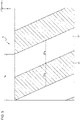
- the transmissive portions 62 are strip areas each elongated in the fourth direction in the plane.
- the fourth direction is at a predetermined angle other than zero with the vertical direction.
- the third direction intersects with the first direction and the second direction.
- the parallax barrier 6 defines the direction of image light emitted from each of the subpixels arranged in the active area 51 to define parts of the active area 51 viewable to the eyes of the user.
- Areas in the active area 51 emitting image light that reaches the positions of the user's eyes are hereafter referred to as viewable areas 51a.
- Areas in the active area 51 emitting image light that reaches the position of the user's left eye are hereafter referred to as left viewable areas 51aL (first viewable areas).
- left viewable areas 51aL first viewable areas
- Areas in the active area 51 emitting image light that reaches the position of the user's right eye are referred to as right viewable areas 51aR (second viewable areas).
- the parallax barrier 6 has multiple less-transmissive portions 61 for reducing image light.
- the multiple less-transmissive portions 61 define transmissive portions 62 between adjacent less-transmissive portions 61.
- the less-transmissive portions 61 and the transmissive portions 62 are arranged alternately in the horizontal direction.
- the width (second width 62w) of each transmissive portion 62 in the horizontal direction can be greater than the width (first width 61w) of each less-transmissive portion 61 in the horizontal direction.
- the parallax barrier 6 can have an aperture ratio greater than 50%.
- the multiple transmissive portions 62 are parts of the parallax barrier 6 to transmit light incident on the parallax barrier 6.
- the transmissive portions 62 have a higher light transmittance than the less-transmissive portions 61.
- the less-transmissive portions 61 have a lower light transmittance than the transmissive portions 62.
- the transmissive portions 62 may transmit light with a transmittance of a first predetermined value or greater.
- the first predetermined value may be, for example, about 100% or a value less than 100%.
- the first predetermined value can be a value less than 100%, such as 80% or 50%, when the image light emitted from the active areas 51 falls within the range of good visibility.
- the less-transmissive portions 61 are parts of the parallax barrier 6 to substantially block light incident on the parallax barrier 6.
- the less-transmissive portions 61 prevent an image displayed in the active area 51 on the display panel 5 from being viewable to the user's eyes.
- the less-transmissive portions 61 may transmit light with a transmittance of a second predetermined value or less.
- the second predetermined value may be, for example, substantially 0% or a greater value close to 0%, such as 0.5%, 1%, or 3%.
- the first predetermined value can be several times, or for example, 10 times, greater than the second predetermined value.
- the first predetermined value can be an appropriate known value selected from the range of values that can create contrast with light transmitted through the less-transmissive portions.
- the transmissive portions 62 and the less-transmissive portions 61 extend in a predetermined direction along the active area 51.
- the transmissive portions 62 and the less-transmissive portions 61 can be arranged alternately in a direction orthogonal to the predetermined direction.
- the transmissive portions 62 define the traveling direction of image light emitted from each of the multiple subpixels.
- a barrier pitch Bp as an interval at which the transmissive portions 62 are arranged in the horizontal direction and the gap g between the active area 51 and the parallax barrier 6 are determined to satisfy Formula 1 and Formula 2 below using an optimum viewing distance d and a standard distance E0.
- the optimum viewing distance d is the distance between the user's right eye or left eye and the parallax barrier 6.
- the horizontal length of each viewable area 51a viewable to each eye is equivalent to n subpixels.
- the direction of a straight line passing through the right eye and the left eye corresponds to the horizontal direction.
- the interocular direction can be different in the physical space.
- the standard distance E0 is the standard interocular distance E of the user.
- the standard distance E0 may be, for example, 61.1 to 64.4 mm, as calculated through studies conducted by the National Institute of Advanced Industrial Science and Technology.
- Hp is the horizontal length of each subpixel as shown in FIG. 2 .
- the parallax barrier 6 may be formed from a film or a plate with a transmittance less than the second predetermined value.
- the less-transmissive portions 61 are parts of the film or plate.
- the transmissive portions 62 are slits in the film or plate.
- the film may be formed from resin or another material.
- the plate may be formed from resin, metal, or another material.
- the parallax barrier 6 may be formed from a material other than a film or a plate.
- the parallax barrier 6 may include a base formed from a light-reducing material or a material containing an additive with light reducing properties.
- the parallax barrier 6 may include, for example, a liquid crystal shutter.
- the liquid crystal shutter can control the transmittance of light in accordance with a voltage applied.
- the liquid crystal shutter may include multiple pixels and control the transmittance of light for each pixel.
- the liquid crystal shutter can form an area with a high light transmittance or an area with a low light transmittance in an intended shape.
- the transmissive portions 62 in the parallax barrier 6 including a liquid crystal shutter may have a transmittance of the first predetermined value or greater.
- the less-transmissive portions 61 in the parallax barrier 6 including a liquid crystal shutter may have a transmittance of the second predetermined value or less.
- the parallax barrier 6 transmits image light emitted from selected subpixels in the active area 51 through the transmissive portions 62 to reach the user's right eye.
- the parallax barrier 6 transmits image light emitted from the other subpixels through the transmissive portions 62 to reach the user's left eye.
- the left viewable areas 51aL are multiple areas defined on the active area 51 viewable to the left eye of the user.
- the image light emitted from the subpixels in the left viewable areas 51aL can pass through the transmissive portions 62 of the parallax barrier 6 and reach the left eye of the user.
- Left unviewable areas 51bL are multiple areas defined on the active area 51 that are not viewable to the left eye of the user.
- the image light emitted from the subpixels in the left unviewable areas 51bL is blocked by the less-transmissive portions 61 of the parallax barrier 6.
- the left viewable areas 51aL include half of the subpixels P1, all of the subpixels P2 to P5, half of the subpixels P6, half of the subpixels P7, and half of the subpixels P12.
- the right viewable areas 51aR shown in FIG. 4 are multiple areas defined on the active area 51 viewable to the right eye of the user.
- the image light emitted from the subpixels in the right viewable areas 51aR can pass through the transmissive portions 62 of the parallax barrier 6 and reach the right eye of the user.
- Right unviewable areas 51bR are multiple areas not viewable to the right eye of the user.
- the image light emitted from the subpixels in the right unviewable areas 51bR is blocked by the less-transmissive portions 61 of the parallax barrier 6.
- the right viewable areas 51aR include half of the subpixels PI, half of the subpixels P6, half of the subpixels P7, all of the subpixels P8 to P11, and half of the subpixels P1.
- Binocular viewable areas 51aLR are the areas of overlap between the left viewable areas 51aL and the right viewable areas 51aR.
- the image light emitted from the subpixels in the binocular viewable areas 51aLR can pass through the transmissive portions 62 of the parallax barrier 6 and reach the right eye and the left eye of the user.
- multiple binocular viewable areas 51aLR constantly occur on the parallax barrier 6 with an aperture ratio of 50% or greater.
- the aperture ratio of the parallax barrier 6 can be calculated using the width of each slit portion 62 relative to the barrier pitch Bp.
- the width of each binocular viewable area can be smaller than the horizontal length Hp of each subpixel.
- the left eye image displayed by the subpixels P1 to P6 and the right eye image displayed by the subpixels P7 to P12 are viewable to the left eye and the right eye.
- the left eye image and the right eye image are parallax images having parallax between them.
- the subpixels L display the left eye image.
- the subpixels R display the right eye image.
- the subpixels C display a common image that is common to the right eye and the left eye.
- the common image which is either the left image or the right eye image, can increase crosstalk.
- the controller 7 may be connected to each of the components of the 3D display system 100 to control these components.
- the components controlled by the controller 7 include the detector 1 and the display panel 5.
- the controller 7 may be, for example, a processor.
- the controller 7 may include one or more processors.
- the processors may include a general-purpose processor that reads a specific program and performs a specific function, and a processor dedicated to specific processing.
- the dedicated processor may include an application-specific integrated circuit (ASIC).
- the processor may include a programmable logic device (PLD).
- the PLD may include a field-programmable gate array (FPGA).
- the controller 7 may be either a system on a chip (SoC) or be a system in a package (SiP) in which one or more processors cooperate with other components.
- the controller 7 may include a storage to store various items of information or programs to operate each component of the 3D display system 100.
- the storage may be, for example, a semiconductor memory.
- the storage may
- the memory 8 may include a random-access memory (RAM) or a read-only memory (ROM).
- the memory 8 stores one or more of a first table, a second table, and a third table, which will be described in detail later.
- the memory 8 stores one or more of a fourth table, a fifth table, and a sixth table, which will be described in detail later.
- the controller 7 can cause a black image as a common image to be displayed in the binocular viewable areas 51aLR.
- the controller 7 causes a black image to be displayed in each binocular viewable area 51aLR to reduce crosstalk substantially viewable to the user.
- This structure provides an appropriate 3D image to the user when, for example, the parallax separation allowed by the parallax barrier 6 is incomplete, such as when the aperture ratio is 50% or greater.
- the controller 7 can cause a black image to be displayed by two subpixels at the boundaries between the left viewable areas 51aL and the right viewable areas 51aR in one subpixel group Pg.
- the binocular viewable areas 51aLR occur at the boundaries between the right viewable areas 51aR and the left viewable areas 51aL.
- the controller 7 can reduce crosstalk substantially viewable to the user.
- the controller 7 can cause a black image to be displayed by subpixels on both ends of the right viewable areas 51aR and the left viewable areas 51aL in the horizontal direction.
- the controller 7 can reduce crosstalk substantially occurring between adjacent subpixel groups Pg.
- a black image displayed in each binocular viewable area can reduce crosstalk caused by light diffraction.
- the 3D display system 100 may be included in a head-up display system 400.
- the head-up display system 400 is also referred to as an HUD 400.
- the HUD 400 includes the 3D display system 100, an optical member 410, and a projection reception member 420 including a projection screen 430.
- the HUD 400 directs image light from the 3D display system 100 to reach the projection reception member 420 through the optical member 410.
- the HUD 400 directs image light reflected on the projection reception member 420 to reach the left eye and the right eye of a user.
- the HUD 400 directs the image light to travel from the 3D display system 100 to the user's left and right eyes along an optical path 440 indicated by a broken line. The user can thus view image light reaching the eyes along the optical path 440 as a virtual image 450.
- an HUD 400 including a 3D display system 200 may be mounted on a movable object 10.
- the HUD 400 may include components that also serve as other devices or components included in the movable object 10.
- the movable object 10 may use a windshield as the projection reception member 420.
- the devices or components of the movable object 10 serving as devices or components included in the HUD 400 may be referred to as HUD modules or 3D display components.
- the HUD 400 and the 3D display system 100 may be mounted on the movable object 10.
- the movable object according to one or more embodiments of the present disclosure includes a vehicle, a vessel, or an aircraft.
- the vehicle includes, but is not limited to, an automobile or an industrial vehicle, and may also include a railroad vehicle, a community vehicle, or a fixed-wing aircraft traveling on a runway.
- the automobile includes, but is not limited to, a passenger vehicle, a truck, a bus, a motorcycle, or a trolley bus, and may also include another vehicle traveling on a road.
- the industrial vehicle includes an agricultural vehicle or a construction vehicle.
- the industrial vehicle includes, but is not limited to, a forklift or a golf cart.
- the agricultural vehicle includes, but is not limited to, a tractor, a cultivator, a transplanter, a binder, a combine, or a lawn mower.
- the construction vehicle includes, but is not limited to, a bulldozer, a scraper, a power shovel, a crane vehicle, a dump truck, or a road roller.
- the vehicle includes a man-powered vehicle.
- the classification of the vehicle is not limited to the above.
- the automobile may include an industrial vehicle traveling on a road, and one type of vehicle may fall within a plurality of classes.
- the vessel according to one or more embodiments of the present disclosure includes a jet ski, a boat, or a tanker.
- the aircraft according to one or more embodiments of the present disclosure includes a fixed-wing aircraft or a rotary-wing aircraft.
- a three-dimensional display device includes a display panel that displays a parallax image, an optical panel including a plurality of less-transmissive portions and a plurality of transmissive portions repeatedly arranged alternately in a parallax direction, and a controller that controls the display panel.
- Each of the plurality of transmissive portions has a first width in the parallax direction greater than a second width of each of the plurality of less-transmissive portions in the parallax direction.
- the controller causes the display panel to display a black image in a binocular viewable area on the display panel viewable to two eyes of a user to allow parallax separation of the parallax image.
- a three-dimensional display system includes a detector that detects a position of a first eye of a user and a position of a second eye of the user different from the first eye, and a three-dimensional display device including a display panel that displays a parallax image, an optical panel including a plurality of less-transmissive portions and a plurality of transmissive portions repeatedly arranged alternately in a parallax direction, and a controller that controls the display panel.
- Each of the plurality of transmissive portions has a first width in the parallax direction greater than a second width of each of the plurality of less-transmissive portions in the parallax direction.
- the controller causes the display panel to display a black image in a binocular viewable area on the display panel viewable to the first eye and the second eye of the user to allow parallax separation of the parallax image.
- a movable object includes a three-dimensional display device including a display panel that displays a parallax image, an optical panel including a plurality of less-transmissive portions and a plurality of transmissive portions repeatedly arranged alternately in a parallax direction, and a controller that controls the display panel.
- Each of the plurality of transmissive portions has a first width in the parallax direction greater than a second width of each of the plurality of less-transmissive portions in the parallax direction.
- the controller causes the display panel to display a black image in a binocular viewable area on the display panel viewable to two eyes of a user to allow parallax separation of the parallax image.
- the 3D display device can have larger slits in the parallax barrier.
Landscapes
- Physics & Mathematics (AREA)
- Engineering & Computer Science (AREA)
- Multimedia (AREA)
- Signal Processing (AREA)
- Optics & Photonics (AREA)
- General Physics & Mathematics (AREA)
- Geometry (AREA)
- Testing, Inspecting, Measuring Of Stereoscopic Televisions And Televisions (AREA)
Applications Claiming Priority (2)
| Application Number | Priority Date | Filing Date | Title |
|---|---|---|---|
| JP2019181616A JP2021057844A (ja) | 2019-10-01 | 2019-10-01 | 3次元表示装置、3次元表示システム及び移動体 |
| PCT/JP2020/037464 WO2021066111A1 (fr) | 2019-10-01 | 2020-10-01 | Dispositif d'affichage tridimensionnel, système d'affichage tridimensionnel, et objet mobile |
Publications (2)
| Publication Number | Publication Date |
|---|---|
| EP4040787A1 true EP4040787A1 (fr) | 2022-08-10 |
| EP4040787A4 EP4040787A4 (fr) | 2023-06-21 |
Family
ID=75272885
Family Applications (1)
| Application Number | Title | Priority Date | Filing Date |
|---|---|---|---|
| EP20871430.3A Pending EP4040787A4 (fr) | 2019-10-01 | 2020-10-01 | Dispositif d'affichage tridimensionnel, système d'affichage tridimensionnel, et objet mobile |
Country Status (5)
| Country | Link |
|---|---|
| US (1) | US20220345686A1 (fr) |
| EP (1) | EP4040787A4 (fr) |
| JP (1) | JP2021057844A (fr) |
| CN (1) | CN114503555A (fr) |
| WO (1) | WO2021066111A1 (fr) |
Family Cites Families (11)
| Publication number | Priority date | Publication date | Assignee | Title |
|---|---|---|---|---|
| JP2902957B2 (ja) | 1994-02-25 | 1999-06-07 | 三洋電機株式会社 | 立体表示装置 |
| JP2000078617A (ja) * | 1998-09-01 | 2000-03-14 | Sharp Corp | 立体画像表示装置 |
| KR100759393B1 (ko) * | 2005-06-29 | 2007-09-19 | 삼성에스디아이 주식회사 | 패럴랙스 배리어 및 이를 구비한 입체 영상 표시장치 |
| JP2012058599A (ja) * | 2010-09-10 | 2012-03-22 | Sony Corp | 立体画像表示装置および画像表示素子 |
| US9432658B2 (en) * | 2011-06-20 | 2016-08-30 | Panasonic Intellectual Property Corporation Of America | Image display device |
| KR101924058B1 (ko) * | 2012-04-03 | 2018-11-30 | 엘지전자 주식회사 | 영상표시장치 및 그 동작방법 |
| CN104994373A (zh) * | 2015-07-31 | 2015-10-21 | 京东方科技集团股份有限公司 | 三维显示装置及三维显示方法 |
| KR101899981B1 (ko) * | 2016-12-02 | 2018-09-19 | 엘지전자 주식회사 | 차량용 헤드 업 디스플레이 |
| JP6889434B2 (ja) * | 2017-01-27 | 2021-06-18 | 公立大学法人大阪 | 3次元表示装置、3次元表示システム、ヘッドアップディスプレイシステム、及び移動体 |
| JP7120537B2 (ja) * | 2017-10-31 | 2022-08-17 | 公立大学法人大阪 | 3次元表示装置、3次元表示システム、ヘッドアップディスプレイおよび3次元表示装置設計方法 |
| JP7129789B2 (ja) * | 2018-02-19 | 2022-09-02 | 京セラ株式会社 | ヘッドアップディスプレイ、ヘッドアップディスプレイシステム、および移動体 |
-
2019
- 2019-10-01 JP JP2019181616A patent/JP2021057844A/ja active Pending
-
2020
- 2020-10-01 WO PCT/JP2020/037464 patent/WO2021066111A1/fr unknown
- 2020-10-01 EP EP20871430.3A patent/EP4040787A4/fr active Pending
- 2020-10-01 US US17/765,372 patent/US20220345686A1/en active Pending
- 2020-10-01 CN CN202080068635.9A patent/CN114503555A/zh active Pending
Also Published As
| Publication number | Publication date |
|---|---|
| EP4040787A4 (fr) | 2023-06-21 |
| CN114503555A (zh) | 2022-05-13 |
| JP2021057844A (ja) | 2021-04-08 |
| US20220345686A1 (en) | 2022-10-27 |
| WO2021066111A1 (fr) | 2021-04-08 |
Similar Documents
| Publication | Publication Date | Title |
|---|---|---|
| EP3650922B1 (fr) | Dispositif d'affichage tridimensionnel, système d'affichage tridimensionnel, corps mobile et procédé d'affichage tridimensionnel | |
| US11343484B2 (en) | Display device, display system, and movable vehicle | |
| US20200053352A1 (en) | Three-dimensional display apparatus, three-dimensional display system, head-up display system, and mobile body | |
| EP4040218A1 (fr) | Dispositif d'affichage tridimensionnel, dispositif de commande, procédé et système d'affichage tridimensionnel et corps mobile | |
| US20230004002A1 (en) | Head-up display, head-up display system, and movable body | |
| EP4067970A1 (fr) | Système d'affichage tête haute et unité mobile | |
| WO2020130049A1 (fr) | Dispositif d'affichage tridimensionnel, système d'affichage tête haute et corps mobile | |
| CN112352422B (zh) | 三维显示装置、控制器、三维显示方法、三维显示系统以及移动体 | |
| EP4040787A1 (fr) | Dispositif d'affichage tridimensionnel, système d'affichage tridimensionnel, et objet mobile | |
| US11881130B2 (en) | Head-up display system and moving body | |
| US11693240B2 (en) | Three-dimensional display device, three-dimensional display system, head-up display, and movable object | |
| WO2020130048A1 (fr) | Dispositif d'affichage tridimensionnel, système d'affichage tête haute et objet mobile | |
| EP4220621A1 (fr) | Dispositif d'affichage tridimensionnel, procédé d'affichage tridimensionnel, système d'affichage tridimensionnel et objet mobile | |
| US11961429B2 (en) | Head-up display, head-up display system, and movable body | |
| EP4276523A1 (fr) | Dispositif d'affichage tridimensionnel | |
| EP4184238A1 (fr) | Dispositif d'affichage tridimensionnel | |
| US20220402361A1 (en) | Head-up display module, head-up display system, and movable body | |
| US20220264077A1 (en) | Three-dimensional display device, three-dimensional display system, and movable object |
Legal Events
| Date | Code | Title | Description |
|---|---|---|---|
| STAA | Information on the status of an ep patent application or granted ep patent |
Free format text: STATUS: THE INTERNATIONAL PUBLICATION HAS BEEN MADE |
|
| PUAI | Public reference made under article 153(3) epc to a published international application that has entered the european phase |
Free format text: ORIGINAL CODE: 0009012 |
|
| STAA | Information on the status of an ep patent application or granted ep patent |
Free format text: STATUS: REQUEST FOR EXAMINATION WAS MADE |
|
| 17P | Request for examination filed |
Effective date: 20220331 |
|
| AK | Designated contracting states |
Kind code of ref document: A1 Designated state(s): AL AT BE BG CH CY CZ DE DK EE ES FI FR GB GR HR HU IE IS IT LI LT LU LV MC MK MT NL NO PL PT RO RS SE SI SK SM TR |
|
| DAV | Request for validation of the european patent (deleted) | ||
| DAX | Request for extension of the european patent (deleted) | ||
| P01 | Opt-out of the competence of the unified patent court (upc) registered |
Effective date: 20230505 |
|
| A4 | Supplementary search report drawn up and despatched |
Effective date: 20230523 |
|
| RIC1 | Information provided on ipc code assigned before grant |
Ipc: H04N 13/317 20180101ALI20230516BHEP Ipc: G02B 30/32 20200101ALI20230516BHEP Ipc: G02B 27/01 20060101ALI20230516BHEP Ipc: G02B 27/00 20060101ALI20230516BHEP Ipc: H04N 13/366 20180101ALI20230516BHEP Ipc: G02B 30/30 20200101ALI20230516BHEP Ipc: H04N 13/31 20180101AFI20230516BHEP |