EP4040733A1 - Leistungsstarke geteilte nutzung von ressourcen zwischen verbundenen iot-objekten, die ein lokales netzwerk bilden - Google Patents
Leistungsstarke geteilte nutzung von ressourcen zwischen verbundenen iot-objekten, die ein lokales netzwerk bilden Download PDFInfo
- Publication number
- EP4040733A1 EP4040733A1 EP21305175.8A EP21305175A EP4040733A1 EP 4040733 A1 EP4040733 A1 EP 4040733A1 EP 21305175 A EP21305175 A EP 21305175A EP 4040733 A1 EP4040733 A1 EP 4040733A1
- Authority
- EP
- European Patent Office
- Prior art keywords
- target operation
- resource
- objects
- management unit
- connected object
- Prior art date
- Legal status (The legal status is an assumption and is not a legal conclusion. Google has not performed a legal analysis and makes no representation as to the accuracy of the status listed.)
- Granted
Links
Images

Classifications
-
- H—ELECTRICITY
- H04—ELECTRIC COMMUNICATION TECHNIQUE
- H04L—TRANSMISSION OF DIGITAL INFORMATION, e.g. TELEGRAPHIC COMMUNICATION
- H04L67/00—Network arrangements or protocols for supporting network services or applications
- H04L67/01—Protocols
- H04L67/12—Protocols specially adapted for proprietary or special-purpose networking environments, e.g. medical networks, sensor networks, networks in vehicles or remote metering networks
- H04L67/125—Protocols specially adapted for proprietary or special-purpose networking environments, e.g. medical networks, sensor networks, networks in vehicles or remote metering networks involving control of end-device applications over a network
-
- H—ELECTRICITY
- H04—ELECTRIC COMMUNICATION TECHNIQUE
- H04L—TRANSMISSION OF DIGITAL INFORMATION, e.g. TELEGRAPHIC COMMUNICATION
- H04L41/00—Arrangements for maintenance, administration or management of data switching networks, e.g. of packet switching networks
- H04L41/50—Network service management, e.g. ensuring proper service fulfilment according to agreements
- H04L41/5041—Network service management, e.g. ensuring proper service fulfilment according to agreements characterised by the time relationship between creation and deployment of a service
- H04L41/5051—Service on demand, e.g. definition and deployment of services in real time
-
- H—ELECTRICITY
- H04—ELECTRIC COMMUNICATION TECHNIQUE
- H04L—TRANSMISSION OF DIGITAL INFORMATION, e.g. TELEGRAPHIC COMMUNICATION
- H04L67/00—Network arrangements or protocols for supporting network services or applications
- H04L67/50—Network services
- H04L67/51—Discovery or management thereof, e.g. service location protocol [SLP] or web services
-
- H—ELECTRICITY
- H04—ELECTRIC COMMUNICATION TECHNIQUE
- H04L—TRANSMISSION OF DIGITAL INFORMATION, e.g. TELEGRAPHIC COMMUNICATION
- H04L67/00—Network arrangements or protocols for supporting network services or applications
- H04L67/50—Network services
- H04L67/56—Provisioning of proxy services
- H04L67/562—Brokering proxy services
Definitions
- the present invention relates to a method for efficient sharing of resources between connected objects forming a local area network. It also relates to a system implementing such a method.
- the field of the invention is the field of the Internet of Things (IoT), and in particular the field of the management of resources and functionalities in the field of IoT.
- IoT Internet of Things
- the Internet of Things or Internet Of Things (IoT)
- IoT Internet Of Things
- connected objects which are interconnected with each other without going through the Internet network.
- the IoT is a field in full expansion and its fields of application are increasingly varied: smart city, intelligent management of a house, monitoring of installations, autonomous cars, etc...
- Connected objects can communicate through local sub-networks, the latter being able to be interconnected with each other thanks, for example, to the Internet.
- the connected objects can communicate with each other in the local network, and the local network can communicate with other local networks of connected objects, through the Internet.
- the connected objects found within a local network can be very varied and can be provided to implement very different functions.
- the objects connected within a local network can for example include smoke detectors, household appliances, locks, shutters, tablets, etc. Each of these objects is dedicated to performing at least one function for which it is designed. These examples are, of course, not limiting.
- each connected object is sized in hardware and/or software resources by considering this object individually and independent of other connected objects, whether in terms of computing resources, storage resources, sensors, communication resources, etc.
- This design of the connected object can make said connected object expensive and complex to design and manufacture.
- An object of the present invention is to remedy this drawback.
- Another object of the present invention is to propose a solution for sharing resources between connected objects making it possible to reduce the manufacturing cost and the complexity of a connected object.
- Another object of the present invention is to propose a solution for efficient sharing of resources between connected objects.
- the invention proposes to implement a management unit to control the sharing of resources, hardware or software, within a network of objects connected within the local network.
- This management unit makes it possible to plan and manage the access of each connected object to the resources equipping other connected objects and which are shared within said local network, these resources being listed in a list of shared resources.
- the method according to the invention proposes to select the connected object offering the most efficient resource, when the requested resource is available within several connected objects.
- the method according to the invention proposes to select the connected object offering the most efficient resource, when the requested resource is available within several connected objects.
- the invention makes it possible to achieve a more efficient sharing of resources between connected objects.
- the invention thus makes it possible to better exploit the resources shared within the local network and to adjust the resource sharing in a more appropriate manner.
- the resources are shared within the local network formed by the connected objects which are interconnected with each other, without leaving said local network.
- the sharing of resources between the connected objects of the local network does not require an Internet connection but only a connection to the management unit located within the local network. In other words, resource sharing is done locally.
- the management unit makes it possible to link the connected objects of the local network for the shared use of resources available within said local network, at the level of each connected object, so that the resources of a connected object can be used for the needs of another connected object.
- resource or “computer resource” can be used to designate a hardware or software resource shared within the network, without loss of generality.
- a resource is said to be "shared" by a second object with a first object, when a data processing operation, called target operation, is performed by said second object on behalf of said first object. using this resource.
- the data processing operation can be carried out immediately when the first object sends a request in this direction, when the resource for carrying out this data processing operation is available immediately.
- the data processing operation is scheduled for subsequent performance depending on the availability of the resource needed to perform said operation.
- the scheduled operation is stored in a list of scheduled operations which may be the list of shared resources, or another list.
- the shared resource list lists all the resources shared within the local network by each connected object.
- the list of shared resources can be individual to at least one connected object.
- the list of shared resources can be a list common to at least two, and in particular, to all the connected objects forming the local area network.
- the shared resource can be deleted from the list, at least during its use on behalf of the first connected object, or for a period during which it is allocated to said first connected object.
- the list of shared resources only mentions the resources available at a given time.
- availability data associated with said resource in the list of shared resources can be modified to modify any of the parameters listed above, namely the duration, the schedule or the availability rate.
- the list of shared resources mentions all the shared resources, indicating for each resource their availability at a given instant.
- the availability of a resource equipping a connected object can be determined in several ways.
- a software package installed within said connected object can provide information concerning the use of each computer resource of said connected object. This information can be used to deduce the availability or not of each resource at a given time. From this information, it is possible to establish, for each resource, an availability schedule for sharing said resource with the other connected objects forming part of said network.
- the connected object it is possible to deploy within the connected object one or more software probes making it possible to carry out system measurements from the operating system of said connected object.
- monitoring software applications making it possible to deploy this type of probe, such as for example the applications known as nmon, perfmon, System Monitoring Lite, iKeyMonitor.
- the use of this or that monitoring solution may depend on the operating system of the connected object.
- the level of utilization of a resource can be a simple or complex indicator. In the case of a sensor, it is a simple flag indicating whether or not it is polled. In the case of a resource such as the CPU, it is a complex indicator indicating both its level of use, but also its level of wait (Wait) or the number of processes waiting for treatment. In the case of a resource such as disk I/Os, this is again a complex indicator (number of read I/Os, number of write I/Os, Idle Time, Current Disk tail Length).
- An availability schedule can be a daily schedule or a weekly schedule, etc.
- the candidate connected objects can be identified, by the management unit, by consulting the list of shared resources.
- the management unit consults the list of shared resources to determine which connected objects offer the resource R1, on the date D1 and for a duration at least equal to T1 if necessary. If no connected object offers the resource R1 with this availability then the first connected object cannot benefit from the resource of another connected object to perform the operation OP1. If a single connected object offers the resource R1 with this availability then this connected object is selected as the second object to perform the operation OP1 on behalf of the first connected object.
- each of these objects is a candidate object for sharing this resource R1 with the first connected object, on date D1 for a duration T1 if necessary, to carry out operation OP1 on behalf of the first connected object.
- At least one, in particular each, performance indicator can be stored in at least one list of performance indicator(s), for example stored in the management unit, in association with a connected object and a target operation.
- the stored value can be the last value measured, or an average of the values measured for several, or even all, of the executions of the operation target by this connected object.
- a list of performance indicator(s) can be individual to at least one, and in particular to each connected object.
- this list indicates for each target operation, or type of target operations, the value of the or each performance indicator of this connected object, measured in the past.
- a list of performance indicator(s) can be common to several, or even to all the connected objects.
- the or each list of performance indicator(s) can be maintained and/or updated by the management unit according to values measured at the level of each connected object and communicated to said management unit.
- At least one performance indicator of a connected object for performing a target operation can be measured by a probe equipping said connected object.
- a probe equipping said connected object can be deployed by the management unit, or can equip the connected object, in particular natively.
- the computing resources consumed by a connected object to perform a data processing operation can be measured by a monitoring probe of the CPU of said connected object.
- the energy consumed by a printer to print a page can be measured by deploying a probe monitoring the electrical consumption of said printer.
- At least one probe deployed in a connected object to measure a performance indicator can be a probe deployed to measure the use of a computer resource of said connected object in order to determine the availability of said resource.
- the same probe deployed in the connected object can both be used to determine resource availability data and measure the value of a performance indicator.
- the method according to the invention may comprise, following the selection step, an assignment of the target operation to the second object.
- This allocation includes making the resource of the second object immediately available to the first object, for immediate triggering of the target operation.
- this allocation may comprise a planning, at a future date, of making the first object available to the resource of the second object, for performance at a later date of the target operation.
- the planned target operation can be signaled to the second object which can add it to its agenda.
- the planned target operation can be stored in a list, and in particular in the list of shared resources.
- the list of shared resources can be updated, as described above.
- the management unit is configured to implement the steps of the method according to the invention.
- the management unit can be installed in, or can be formed by, a dedicated device located within the local network.
- this device is not intended to perform another function or another task, as opposed to the connected objects found in the network.
- the management unit can be installed in a connected object located in the local network, and provided and designed to perform at least one other task, similarly to connected objects located in the local network.
- At least one connected object can comprise a software module, called client planning module, to determine at least one availability datum of at least one resource of said connected object and which can be shared within the local network.
- Such a client planning module can be configured to monitor the nature and/or the quantity of resources consumed within said connected object for the performance of the tasks for which said connected object is intended. Thus, it is possible to determine, for each resource, the periods during which said resource is not used, or little used, by said connected object and is therefore available to carry out operations on behalf of other connected objects.
- such a client planning module can be native.
- such a client planning module can be deployed in said connected object subsequently, for example by the management unit.
- the system according to the invention may further comprise at least one means for measuring the value of a performance indicator of an object connected to perform a target operation, or a type of target operation.
- At least one connected object can comprise a software module, called client measurement module, to measure the value of at least one performance indicator of said connected object when it performs a target operation or a type of target operation.
- client measurement module a software module, called client measurement module
- such a client measurement module can be native.
- such a client measurement module can be deployed in said connected object, for example by the management unit.
- At least one customer planning module is partly or totally a customer measurement module, and vice versa.
- a connected object within the meaning of the present invention can be any connected object.
- the connected objects can be connected objects present in a home such as an alarm, a roller shutter control unit, a household appliance, forming a local network within said home.
- the connected objects can be connected objects present in a professional place, in a public place, etc.
- the FIGURE 1 is a schematic representation of a non-limiting exemplary embodiment of a method according to the invention.
- Process 100 shown in FIGURE 1 , can be used to pool resources in a local network comprising at least two connected objects and a management unit connected to each of said connected objects.
- the method 100 comprises a step 102 during which a connected object, called the first connected object, without loss of generality, sends a request for access to a resource which could be shared by another connected object within the local network, to carry out a target operation.
- the request provides for entrusting the performance of a target operation OP1 requiring a resource R1 to another object connected within the local network which has said resource R1.
- This access request is sent to the management unit within the local network.
- the management unit determines whether the local network includes one or more connected objects offering the requested resource, namely the data encryption software, for sharing. For this, the management unit consults a list, denoted LRP, listing each shared resource within the network, the connected object having shared this resource, and possibly (but preferentially) a schedule for sharing the resource, said planning which can include the moments of availability of the resource, a duration of availability of the resource, a rate of availability of the resource, etc.
- LRP list, denoted LRP, listing each shared resource within the network, the connected object having shared this resource, and possibly (but preferentially) a schedule for sharing the resource, said planning which can include the moments of availability of the resource, a duration of availability of the resource, a rate of availability of the resource, etc.
- step 106 When in step 106, there is a single connected object which shares the resource requested by the first object in accordance with the request sent by the first object, then this object is chosen by the management unit as the second object when a step 108.
- the list of shared resources LRP can be updated, by the management unit, to modify the availability of the resource shared by the second object.
- each of these connected objects is considered as a candidate connected object to share its resource with the first object.
- the management unit consults a file, referenced LIP, in which is stored the value of each performance indicator of each candidate connected object for carrying out the target operation. The values of each performance indicator relating to the target operation are compared during step 110, to identify the candidate connected object exhibiting the best performance indicator.
- the candidate connected object presenting the best performance indicator(s) is chosen as the second connected object.
- the list of shared resources LRP is updated, by the management unit, to modify the availability of the resource shared by said second object.
- the updating of the LRP list can be carried out in different ways to modify the availability of a resource offered for sharing by a second connected object when said resource has actually been shared with the first connected object, immediately or at a future date.
- the shared resource can be deleted from the list, at least during its use on behalf of the first connected object, or for a period during which it is allocated to said first connected object.
- the list of shared resources only mentions the resources available at a given instant, for each instant.
- the availability of a resource equipping a connected object can be determined by a software probe, equipping said connected object or deployed in said connected object by the management unit, to measure and provide data concerning the use of said resource within said connected object. These data can be used to deduce the availability or otherwise of said resource at a given moment, and in particular its duration and/or its availability rate.
- an availability schedule to share said resource with the other connected objects forming part of said network. This schedule can be stored in the LRP list.
- An availability schedule can be a daily schedule or a weekly schedule, etc.
- a performance indicator of a connected object for performing a target operation can be measured during at least one past performance, by said connected object, of said target operation or of an operation of the same type.
- the value stored in the LIP file can be the last measured value for the performance indicator, or an average of several measured values.
- FIGURE 2 is a schematic representation of another non-limiting embodiment of a method according to the invention.
- Process 200 shown in FIGURE 2 , can be used to pool resources in a local network comprising at least two connected objects.
- Method 200 includes all of the steps of Method 100 from FIGURE 1 .
- the method 200 further comprises a step 202 triggering the execution of the target operation by the second object on behalf of the first connected object.
- This step 202 can be implemented immediately after step 108, or step 112, in the case of immediate resource sharing.
- the step 202 can be implemented at a future date after the implementation of the steps of the method 100, in the case of a future sharing planned at a future date.
- a step 204 performs the measurement of at least one value of at least one performance indicator, such as a quantity of calculation resource used to perform the target operation, an electrical power consumed to perform the target operation, a duration for performing the target operation, by appropriate software probes and/or hardware probes equipping the second connected object, or deployed in the second object by the management unit.
- at least one performance indicator such as a quantity of calculation resource used to perform the target operation, an electrical power consumed to perform the target operation, a duration for performing the target operation, by appropriate software probes and/or hardware probes equipping the second connected object, or deployed in the second object by the management unit.
- the results of this target operation are communicated by the second object connected to the first object connected, directly or via the management unit.
- the value of each performance indicator of the second connected object is updated in the LIP file according to the measurement(s) carried out during step 204 , for this target operation.
- This update can be performed directly by the second connected object, or preferably, by the management unit.
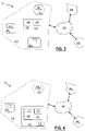
- FIGURE 3 is a schematic representation of a non-limiting exemplary embodiment of a system according to the invention.
- System 300 shown in FIGURE 3 , can be used for the implementation of a method for sharing resources within a local network of connected objects, in particular the method 100 of the FIGURE 1 or method 200 of the FIGURE 2 .
- the system 300 comprises a total of three connected objects 302 1 , 302 2 , 302 3 , also designated by the reference 302 i or 302 below.
- the number of connected objects is not limited to 3 and can be greater than or equal to 2.
- the connected objects 302 form a local network 304 and are interconnected with each other.
- each connected object 302 i is in communication with each of the other connected objects 302 i .
- Each connected object 302 i performs one or more tasks for which it is designed.
- the connected objects 302 i can be connected objects located within a dwelling, such as an alarm, a household appliance, etc. forming a local area network 304 within said dwelling.
- the local network 304 can be connected to one or more other networks 306 1 -306 n , local or not, for example through a communication network 308 such as the Internet.
- the system 300 further comprises a management unit 310, in communication with each of the connected objects 302 1 -302 3 .
- This management unit 310 is configured to implement all the steps of the method according to the invention, and in particular of the method 100 of the FIGURE 1 or method 200 of the FIGURE 2 .
- the management unit 310 can also be configured to establish an availability schedule for at least one resource, software or hardware, of one or more connected objects 302 i to be shared with at least one other connected object 302 i of the local network 304, that is to say to carry out operations on behalf of another connected object 302 i within said local network 304.
- the management unit 310 can comprise a central planning module 312, in particular software, and deploying in each connected object 302 1 -302 3 a client planning software module, respectively 314 1 -314 3 .
- Each client planning module 314 i equipping a connected object 302 i has the function of monitoring the use of the resources with which said connected object 302 i is equipped and informing the central planning module 312 so that said central planning module 312 can establish an availability schedule for each resource within each connected object 302 i .
- the client planning module 314 i can be a native module present in said connected object 302 i so that it is not deployed by the management unit.
- the management unit 310 can also be configured to implement a mechanism for measuring performance indicators and updating the LIP file.
- this mechanism for measuring performance indicators can use a dedicated client measurement module, or use the client module 314 i deployed in said connected object 302 i and measure at least one performance indicator when said object connected 302 i performs a target operation, or a type of target operation.
- the performance indicator can be any of the performance indicators described above.
- the management unit 310 can include a module 318, called the central measurement module, to drive the measurement of performance indicators and update the value of each performance indicator. This central measurement module 318 can request each client planning module 314 i to measure the value of at least one performance indicator, receive the measured value and update the LIP file.
- each client planning module 314 i used to determine the availability of the resources of a connected object 302 i is used as a client measurement module to measure the value of at least one performance indicator of this connected object.
- the management unit 310 is integrated into a dedicated device, independent of the connected objects, and performing no other task.
- the FIGURE 4 is a schematic representation of another non-limiting embodiment of a system for pooling resources between connected objects forming a local area network.
- System 400 shown in FIGURE 4 , can be used for the implementation of a resource sharing method within a local network of connected objects, in particular the method 100 of the FIGURE 1 or method 200 of the FIGURE 2 .
- System 400 includes all elements of System 300 from the FIGURE 3 , except for the differences noted below.
- the management unit 310 is integrated into the connected object 302 3 .
- the management unit can be integrated into another device such as for example an Internet access point, a switch, etc.
Landscapes
- Engineering & Computer Science (AREA)
- Computer Networks & Wireless Communication (AREA)
- Signal Processing (AREA)
- Health & Medical Sciences (AREA)
- Computing Systems (AREA)
- General Health & Medical Sciences (AREA)
- Medical Informatics (AREA)
- Computer And Data Communications (AREA)
Priority Applications (1)
| Application Number | Priority Date | Filing Date | Title |
|---|---|---|---|
| EP21305175.8A EP4040733B1 (de) | 2021-02-09 | 2021-02-09 | Leistungsstarke geteilte nutzung von ressourcen zwischen verbundenen iot-objekten, die ein lokales netzwerk bilden |
Applications Claiming Priority (1)
| Application Number | Priority Date | Filing Date | Title |
|---|---|---|---|
| EP21305175.8A EP4040733B1 (de) | 2021-02-09 | 2021-02-09 | Leistungsstarke geteilte nutzung von ressourcen zwischen verbundenen iot-objekten, die ein lokales netzwerk bilden |
Publications (2)
| Publication Number | Publication Date |
|---|---|
| EP4040733A1 true EP4040733A1 (de) | 2022-08-10 |
| EP4040733B1 EP4040733B1 (de) | 2024-07-17 |
Family
ID=75625512
Family Applications (1)
| Application Number | Title | Priority Date | Filing Date |
|---|---|---|---|
| EP21305175.8A Active EP4040733B1 (de) | 2021-02-09 | 2021-02-09 | Leistungsstarke geteilte nutzung von ressourcen zwischen verbundenen iot-objekten, die ein lokales netzwerk bilden |
Country Status (1)
| Country | Link |
|---|---|
| EP (1) | EP4040733B1 (de) |
Citations (1)
| Publication number | Priority date | Publication date | Assignee | Title |
|---|---|---|---|---|
| US20200067800A1 (en) * | 2018-08-21 | 2020-02-27 | Fujitsu Limited | Service function chain mapping using multiple parallel microservices instances |
-
2021
- 2021-02-09 EP EP21305175.8A patent/EP4040733B1/de active Active
Patent Citations (1)
| Publication number | Priority date | Publication date | Assignee | Title |
|---|---|---|---|---|
| US20200067800A1 (en) * | 2018-08-21 | 2020-02-27 | Fujitsu Limited | Service function chain mapping using multiple parallel microservices instances |
Non-Patent Citations (2)
| Title |
|---|
| AL RAWAHI AHMED SALIM ET AL: "An Evaluation of Optimisation Approaches in Cloud of Things Resource Trading", 2018 IEEE 6TH INTERNATIONAL CONFERENCE ON FUTURE INTERNET OF THINGS AND CLOUD (FICLOUD), IEEE, 6 August 2018 (2018-08-06), pages 208 - 215, XP033399730, DOI: 10.1109/FICLOUD.2018.00038 * |
| LI FAN ET AL: "A Trust Model for SLA Negotiation Candidates Selection in a Dynamic IoT Environment", IEEE TRANSACTIONS ON SERVICES COMPUTING, vol. 3070405, no. 1, 1 January 2021 (2021-01-01), XP055813137, Retrieved from the Internet <URL:https://ieeexplore.ieee.org/stampPDF/getPDF.jsp?tp=&arnumber=9395239&ref=aHR0cHM6Ly9pZWVleHBsb3JlLmllZWUub3JnL2RvY3VtZW50LzkzOTUyMzk=> DOI: 10.1109/TSC.2021.3070405 * |
Also Published As
| Publication number | Publication date |
|---|---|
| EP4040733B1 (de) | 2024-07-17 |
Similar Documents
| Publication | Publication Date | Title |
|---|---|---|
| US11108575B2 (en) | Training models for IOT devices | |
| US20210235543A1 (en) | Split predictions for iot devices | |
| US20190037040A1 (en) | Model tiering for iot device clusters | |
| BE1025002B1 (fr) | Compilation pour traitement parallele base sur gpu de dispositif de noeud | |
| EP2894872B1 (de) | Verfahren zur Verlaufsplanung der Aufgaben in einem PLC-Netz | |
| EP3824389B1 (de) | Verfahren zur koordination mehrerer vorrichtungsverwaltungsserver | |
| EP3506094B1 (de) | Verfahren und system zur optimisierung der planung von batchprozessen | |
| JP2022068123A (ja) | センサ非依存のジェスチャ検出のためのコンピュータ実装方法、システムおよびコンピュータプログラム製品(センサ非依存のジェスチャ検出) | |
| EP3846417B1 (de) | Verfahren zur gemeinsamen nutzung von iot-funktionen, und vorrichtung zur gemeinsamen nutzung | |
| EP4040733B1 (de) | Leistungsstarke geteilte nutzung von ressourcen zwischen verbundenen iot-objekten, die ein lokales netzwerk bilden | |
| EP2709008B1 (de) | Verfahren und Vorrichtung zur versetzten Zeitabrechnung für Verarbeitungseinheit eines Informationsverarbeitungssystems | |
| EP4040734B1 (de) | Optimierte nutzung von ressourcen zwischen verbundenen iot-objekten, die ein lokales netzwerk bilden | |
| EP3343375B1 (de) | Eine methode und ein system zur überwachung der stapelverarbeitung von anwendungen, die in der it-infrastruktur ausgeführt werden | |
| WO2009013429A2 (fr) | Procede de mesure des performances d'un serveur cible logeant un outil de suivi dynamique | |
| EP3659321B1 (de) | Abgestufte datenverarbeitung für iot-vorrichtungscluster | |
| EP3893470B1 (de) | Verfahren zur optimierung der aktualisierung von verbundenen objekten und anwendungsmodul | |
| EP2996036B1 (de) | Verfahren zur überwachung einer applikationsarchitektur, die eine vielzahl von diensten umfasst | |
| EP4040755B1 (de) | Gemeinsame nutzung von ressourcen zwischen verbundenen iot-objekten, die ein lokales netzwerk bilden | |
| FR2979451A1 (fr) | Procede de determination de la part de la consommation electrique liee aux temperatures exterieures | |
| EP2902762B1 (de) | Verfahren zur Bestimmung einer Wärmesignatur eines Gebäudes durch Temperaturmessung im Zeitverlauf, und entsprechende Vorrichtung | |
| FR3105900A1 (fr) | Procédé de partage ordonnance de FONCTIONNALITES des IoTs et Dispositif de partage ordonnance | |
| US10761900B1 (en) | System and method for secure distributed processing across networks of heterogeneous processing nodes | |
| FR3087556A1 (fr) | Procede d'amelioration de l'efficacite d'utlisation des ressources d'une infrastructure destinee a executer un plan d'ordonnancement | |
| EP3350967B1 (de) | Verfahren zur konfiguration und verfahren zur steuerung einer heimautomationsvorrichtung | |
| EP3926927B1 (de) | Kommunikationsverfahren und damit verbundene objekte |
Legal Events
| Date | Code | Title | Description |
|---|---|---|---|
| PUAI | Public reference made under article 153(3) epc to a published international application that has entered the european phase |
Free format text: ORIGINAL CODE: 0009012 |
|
| STAA | Information on the status of an ep patent application or granted ep patent |
Free format text: STATUS: THE APPLICATION HAS BEEN PUBLISHED |
|
| AK | Designated contracting states |
Kind code of ref document: A1 Designated state(s): AL AT BE BG CH CY CZ DE DK EE ES FI FR GB GR HR HU IE IS IT LI LT LU LV MC MK MT NL NO PL PT RO RS SE SI SK SM TR |
|
| STAA | Information on the status of an ep patent application or granted ep patent |
Free format text: STATUS: REQUEST FOR EXAMINATION WAS MADE |
|
| 17P | Request for examination filed |
Effective date: 20230125 |
|
| RBV | Designated contracting states (corrected) |
Designated state(s): AL AT BE BG CH CY CZ DE DK EE ES FI FR GB GR HR HU IE IS IT LI LT LU LV MC MK MT NL NO PL PT RO RS SE SI SK SM TR |
|
| P01 | Opt-out of the competence of the unified patent court (upc) registered |
Effective date: 20230330 |
|
| REG | Reference to a national code |
Ref country code: DE Ref legal event code: R079 Free format text: PREVIOUS MAIN CLASS: H04L0012240000 Ipc: H04L0067125000 Ref country code: DE Ref legal event code: R079 Ref document number: 602021015790 Country of ref document: DE Free format text: PREVIOUS MAIN CLASS: H04L0012240000 Ipc: H04L0067125000 |
|
| GRAP | Despatch of communication of intention to grant a patent |
Free format text: ORIGINAL CODE: EPIDOSNIGR1 |
|
| STAA | Information on the status of an ep patent application or granted ep patent |
Free format text: STATUS: GRANT OF PATENT IS INTENDED |
|
| RIC1 | Information provided on ipc code assigned before grant |
Ipc: H04L 41/5051 20220101ALI20240208BHEP Ipc: H04L 67/562 20220101ALI20240208BHEP Ipc: H04L 67/51 20220101ALI20240208BHEP Ipc: H04L 67/125 20220101AFI20240208BHEP |
|
| INTG | Intention to grant announced |
Effective date: 20240221 |
|
| GRAS | Grant fee paid |
Free format text: ORIGINAL CODE: EPIDOSNIGR3 |
|
| GRAA | (expected) grant |
Free format text: ORIGINAL CODE: 0009210 |
|
| STAA | Information on the status of an ep patent application or granted ep patent |
Free format text: STATUS: THE PATENT HAS BEEN GRANTED |
|
| AK | Designated contracting states |
Kind code of ref document: B1 Designated state(s): AL AT BE BG CH CY CZ DE DK EE ES FI FR GB GR HR HU IE IS IT LI LT LU LV MC MK MT NL NO PL PT RO RS SE SI SK SM TR |
|
| REG | Reference to a national code |
Ref country code: CH Ref legal event code: EP |
|
| REG | Reference to a national code |
Ref country code: DE Ref legal event code: R096 Ref document number: 602021015790 Country of ref document: DE |
|
| REG | Reference to a national code |
Ref country code: IE Ref legal event code: FG4D Free format text: LANGUAGE OF EP DOCUMENT: FRENCH |
|
| REG | Reference to a national code |
Ref country code: DE Ref legal event code: R081 Ref document number: 602021015790 Country of ref document: DE Owner name: BULL SAS, FR Free format text: FORMER OWNERS: BULL SAS, LES CLAYES-SOUS-BOIS, FR; COMMISSARIAT A L'ENERGIE ATOMIQUE ET AUX ENERGIES ALTERNATIVES, PARIS, FR |
|
| REG | Reference to a national code |
Ref country code: LT Ref legal event code: MG9D |
|
| REG | Reference to a national code |
Ref country code: NL Ref legal event code: MP Effective date: 20240717 |
|
| PG25 | Lapsed in a contracting state [announced via postgrant information from national office to epo] |
Ref country code: PT Free format text: LAPSE BECAUSE OF FAILURE TO SUBMIT A TRANSLATION OF THE DESCRIPTION OR TO PAY THE FEE WITHIN THE PRESCRIBED TIME-LIMIT Effective date: 20241118 |
|
| REG | Reference to a national code |
Ref country code: AT Ref legal event code: MK05 Ref document number: 1705179 Country of ref document: AT Kind code of ref document: T Effective date: 20240717 |
|
| PG25 | Lapsed in a contracting state [announced via postgrant information from national office to epo] |
Ref country code: NL Free format text: LAPSE BECAUSE OF FAILURE TO SUBMIT A TRANSLATION OF THE DESCRIPTION OR TO PAY THE FEE WITHIN THE PRESCRIBED TIME-LIMIT Effective date: 20240717 |
|
| PG25 | Lapsed in a contracting state [announced via postgrant information from national office to epo] |
Ref country code: PT Free format text: LAPSE BECAUSE OF FAILURE TO SUBMIT A TRANSLATION OF THE DESCRIPTION OR TO PAY THE FEE WITHIN THE PRESCRIBED TIME-LIMIT Effective date: 20241118 Ref country code: NL Free format text: LAPSE BECAUSE OF FAILURE TO SUBMIT A TRANSLATION OF THE DESCRIPTION OR TO PAY THE FEE WITHIN THE PRESCRIBED TIME-LIMIT Effective date: 20240717 |
|
| PG25 | Lapsed in a contracting state [announced via postgrant information from national office to epo] |
Ref country code: NO Free format text: LAPSE BECAUSE OF FAILURE TO SUBMIT A TRANSLATION OF THE DESCRIPTION OR TO PAY THE FEE WITHIN THE PRESCRIBED TIME-LIMIT Effective date: 20241017 |
|
| PG25 | Lapsed in a contracting state [announced via postgrant information from national office to epo] |
Ref country code: PL Free format text: LAPSE BECAUSE OF FAILURE TO SUBMIT A TRANSLATION OF THE DESCRIPTION OR TO PAY THE FEE WITHIN THE PRESCRIBED TIME-LIMIT Effective date: 20240717 Ref country code: FI Free format text: LAPSE BECAUSE OF FAILURE TO SUBMIT A TRANSLATION OF THE DESCRIPTION OR TO PAY THE FEE WITHIN THE PRESCRIBED TIME-LIMIT Effective date: 20240717 Ref country code: GR Free format text: LAPSE BECAUSE OF FAILURE TO SUBMIT A TRANSLATION OF THE DESCRIPTION OR TO PAY THE FEE WITHIN THE PRESCRIBED TIME-LIMIT Effective date: 20241018 |
|
| PG25 | Lapsed in a contracting state [announced via postgrant information from national office to epo] |
Ref country code: BG Free format text: LAPSE BECAUSE OF FAILURE TO SUBMIT A TRANSLATION OF THE DESCRIPTION OR TO PAY THE FEE WITHIN THE PRESCRIBED TIME-LIMIT Effective date: 20240717 |
|
| PG25 | Lapsed in a contracting state [announced via postgrant information from national office to epo] |
Ref country code: LV Free format text: LAPSE BECAUSE OF FAILURE TO SUBMIT A TRANSLATION OF THE DESCRIPTION OR TO PAY THE FEE WITHIN THE PRESCRIBED TIME-LIMIT Effective date: 20240717 |
|
| PG25 | Lapsed in a contracting state [announced via postgrant information from national office to epo] |
Ref country code: IS Free format text: LAPSE BECAUSE OF FAILURE TO SUBMIT A TRANSLATION OF THE DESCRIPTION OR TO PAY THE FEE WITHIN THE PRESCRIBED TIME-LIMIT Effective date: 20241117 Ref country code: AT Free format text: LAPSE BECAUSE OF FAILURE TO SUBMIT A TRANSLATION OF THE DESCRIPTION OR TO PAY THE FEE WITHIN THE PRESCRIBED TIME-LIMIT Effective date: 20240717 |
|
| PG25 | Lapsed in a contracting state [announced via postgrant information from national office to epo] |
Ref country code: HR Free format text: LAPSE BECAUSE OF FAILURE TO SUBMIT A TRANSLATION OF THE DESCRIPTION OR TO PAY THE FEE WITHIN THE PRESCRIBED TIME-LIMIT Effective date: 20240717 |
|
| PG25 | Lapsed in a contracting state [announced via postgrant information from national office to epo] |
Ref country code: ES Free format text: LAPSE BECAUSE OF FAILURE TO SUBMIT A TRANSLATION OF THE DESCRIPTION OR TO PAY THE FEE WITHIN THE PRESCRIBED TIME-LIMIT Effective date: 20240717 Ref country code: RS Free format text: LAPSE BECAUSE OF FAILURE TO SUBMIT A TRANSLATION OF THE DESCRIPTION OR TO PAY THE FEE WITHIN THE PRESCRIBED TIME-LIMIT Effective date: 20241017 |
|
| PG25 | Lapsed in a contracting state [announced via postgrant information from national office to epo] |
Ref country code: RS Free format text: LAPSE BECAUSE OF FAILURE TO SUBMIT A TRANSLATION OF THE DESCRIPTION OR TO PAY THE FEE WITHIN THE PRESCRIBED TIME-LIMIT Effective date: 20241017 Ref country code: PL Free format text: LAPSE BECAUSE OF FAILURE TO SUBMIT A TRANSLATION OF THE DESCRIPTION OR TO PAY THE FEE WITHIN THE PRESCRIBED TIME-LIMIT Effective date: 20240717 Ref country code: NO Free format text: LAPSE BECAUSE OF FAILURE TO SUBMIT A TRANSLATION OF THE DESCRIPTION OR TO PAY THE FEE WITHIN THE PRESCRIBED TIME-LIMIT Effective date: 20241017 Ref country code: LV Free format text: LAPSE BECAUSE OF FAILURE TO SUBMIT A TRANSLATION OF THE DESCRIPTION OR TO PAY THE FEE WITHIN THE PRESCRIBED TIME-LIMIT Effective date: 20240717 Ref country code: IS Free format text: LAPSE BECAUSE OF FAILURE TO SUBMIT A TRANSLATION OF THE DESCRIPTION OR TO PAY THE FEE WITHIN THE PRESCRIBED TIME-LIMIT Effective date: 20241117 Ref country code: HR Free format text: LAPSE BECAUSE OF FAILURE TO SUBMIT A TRANSLATION OF THE DESCRIPTION OR TO PAY THE FEE WITHIN THE PRESCRIBED TIME-LIMIT Effective date: 20240717 Ref country code: GR Free format text: LAPSE BECAUSE OF FAILURE TO SUBMIT A TRANSLATION OF THE DESCRIPTION OR TO PAY THE FEE WITHIN THE PRESCRIBED TIME-LIMIT Effective date: 20241018 Ref country code: FI Free format text: LAPSE BECAUSE OF FAILURE TO SUBMIT A TRANSLATION OF THE DESCRIPTION OR TO PAY THE FEE WITHIN THE PRESCRIBED TIME-LIMIT Effective date: 20240717 Ref country code: ES Free format text: LAPSE BECAUSE OF FAILURE TO SUBMIT A TRANSLATION OF THE DESCRIPTION OR TO PAY THE FEE WITHIN THE PRESCRIBED TIME-LIMIT Effective date: 20240717 Ref country code: BG Free format text: LAPSE BECAUSE OF FAILURE TO SUBMIT A TRANSLATION OF THE DESCRIPTION OR TO PAY THE FEE WITHIN THE PRESCRIBED TIME-LIMIT Effective date: 20240717 Ref country code: AT Free format text: LAPSE BECAUSE OF FAILURE TO SUBMIT A TRANSLATION OF THE DESCRIPTION OR TO PAY THE FEE WITHIN THE PRESCRIBED TIME-LIMIT Effective date: 20240717 |
|
| PGFP | Annual fee paid to national office [announced via postgrant information from national office to epo] |
Ref country code: DE Payment date: 20250218 Year of fee payment: 5 |
|
| PG25 | Lapsed in a contracting state [announced via postgrant information from national office to epo] |
Ref country code: RO Free format text: LAPSE BECAUSE OF FAILURE TO SUBMIT A TRANSLATION OF THE DESCRIPTION OR TO PAY THE FEE WITHIN THE PRESCRIBED TIME-LIMIT Effective date: 20240717 Ref country code: SM Free format text: LAPSE BECAUSE OF FAILURE TO SUBMIT A TRANSLATION OF THE DESCRIPTION OR TO PAY THE FEE WITHIN THE PRESCRIBED TIME-LIMIT Effective date: 20240717 Ref country code: DK Free format text: LAPSE BECAUSE OF FAILURE TO SUBMIT A TRANSLATION OF THE DESCRIPTION OR TO PAY THE FEE WITHIN THE PRESCRIBED TIME-LIMIT Effective date: 20240717 |
|
| REG | Reference to a national code |
Ref country code: DE Ref legal event code: R097 Ref document number: 602021015790 Country of ref document: DE |
|
| PG25 | Lapsed in a contracting state [announced via postgrant information from national office to epo] |
Ref country code: EE Free format text: LAPSE BECAUSE OF FAILURE TO SUBMIT A TRANSLATION OF THE DESCRIPTION OR TO PAY THE FEE WITHIN THE PRESCRIBED TIME-LIMIT Effective date: 20240717 |
|
| PG25 | Lapsed in a contracting state [announced via postgrant information from national office to epo] |
Ref country code: CZ Free format text: LAPSE BECAUSE OF FAILURE TO SUBMIT A TRANSLATION OF THE DESCRIPTION OR TO PAY THE FEE WITHIN THE PRESCRIBED TIME-LIMIT Effective date: 20240717 |
|
| PGFP | Annual fee paid to national office [announced via postgrant information from national office to epo] |
Ref country code: FR Payment date: 20250219 Year of fee payment: 5 |
|
| PG25 | Lapsed in a contracting state [announced via postgrant information from national office to epo] |
Ref country code: SK Free format text: LAPSE BECAUSE OF FAILURE TO SUBMIT A TRANSLATION OF THE DESCRIPTION OR TO PAY THE FEE WITHIN THE PRESCRIBED TIME-LIMIT Effective date: 20240717 |
|
| PGFP | Annual fee paid to national office [announced via postgrant information from national office to epo] |
Ref country code: GB Payment date: 20250220 Year of fee payment: 5 |
|
| PLBE | No opposition filed within time limit |
Free format text: ORIGINAL CODE: 0009261 |
|
| STAA | Information on the status of an ep patent application or granted ep patent |
Free format text: STATUS: NO OPPOSITION FILED WITHIN TIME LIMIT |
|
| 26N | No opposition filed |
Effective date: 20250422 |
|
| PG25 | Lapsed in a contracting state [announced via postgrant information from national office to epo] |
Ref country code: SE Free format text: LAPSE BECAUSE OF FAILURE TO SUBMIT A TRANSLATION OF THE DESCRIPTION OR TO PAY THE FEE WITHIN THE PRESCRIBED TIME-LIMIT Effective date: 20240717 |
|
| PG25 | Lapsed in a contracting state [announced via postgrant information from national office to epo] |
Ref country code: MC Free format text: LAPSE BECAUSE OF FAILURE TO SUBMIT A TRANSLATION OF THE DESCRIPTION OR TO PAY THE FEE WITHIN THE PRESCRIBED TIME-LIMIT Effective date: 20240717 |
|
| REG | Reference to a national code |
Ref country code: CH Ref legal event code: PL |
|
| PG25 | Lapsed in a contracting state [announced via postgrant information from national office to epo] |
Ref country code: LU Free format text: LAPSE BECAUSE OF NON-PAYMENT OF DUE FEES Effective date: 20250209 |
|
| PG25 | Lapsed in a contracting state [announced via postgrant information from national office to epo] |
Ref country code: CH Free format text: LAPSE BECAUSE OF NON-PAYMENT OF DUE FEES Effective date: 20250228 |
|
| REG | Reference to a national code |
Ref country code: BE Ref legal event code: MM Effective date: 20250228 |
|
| PG25 | Lapsed in a contracting state [announced via postgrant information from national office to epo] |
Ref country code: BE Free format text: LAPSE BECAUSE OF NON-PAYMENT OF DUE FEES Effective date: 20250228 |
|
| PG25 | Lapsed in a contracting state [announced via postgrant information from national office to epo] |
Ref country code: IE Free format text: LAPSE BECAUSE OF NON-PAYMENT OF DUE FEES Effective date: 20250209 |
|
| PG25 | Lapsed in a contracting state [announced via postgrant information from national office to epo] |
Ref country code: IT Free format text: LAPSE BECAUSE OF FAILURE TO SUBMIT A TRANSLATION OF THE DESCRIPTION OR TO PAY THE FEE WITHIN THE PRESCRIBED TIME-LIMIT Effective date: 20240717 |