EP4040728A1 - Verfahren und system für filterinformationskonfiguration - Google Patents
Verfahren und system für filterinformationskonfiguration Download PDFInfo
- Publication number
- EP4040728A1 EP4040728A1 EP20871463.4A EP20871463A EP4040728A1 EP 4040728 A1 EP4040728 A1 EP 4040728A1 EP 20871463 A EP20871463 A EP 20871463A EP 4040728 A1 EP4040728 A1 EP 4040728A1
- Authority
- EP
- European Patent Office
- Prior art keywords
- point
- fault
- forwarding
- filtering information
- subnetwork
- Prior art date
- Legal status (The legal status is an assumption and is not a legal conclusion. Google has not performed a legal analysis and makes no representation as to the accuracy of the status listed.)
- Granted
Links
Images

Classifications
-
- H—ELECTRICITY
- H04—ELECTRIC COMMUNICATION TECHNIQUE
- H04L—TRANSMISSION OF DIGITAL INFORMATION, e.g. TELEGRAPHIC COMMUNICATION
- H04L41/00—Arrangements for maintenance, administration or management of data switching networks, e.g. of packet switching networks
- H04L41/06—Management of faults, events, alarms or notifications
- H04L41/0604—Management of faults, events, alarms or notifications using filtering, e.g. reduction of information by using priority, element types, position or time
-
- H—ELECTRICITY
- H04—ELECTRIC COMMUNICATION TECHNIQUE
- H04L—TRANSMISSION OF DIGITAL INFORMATION, e.g. TELEGRAPHIC COMMUNICATION
- H04L41/00—Arrangements for maintenance, administration or management of data switching networks, e.g. of packet switching networks
- H04L41/08—Configuration management of networks or network elements
- H04L41/0803—Configuration setting
- H04L41/0823—Configuration setting characterised by the purposes of a change of settings, e.g. optimising configuration for enhancing reliability
-
- H—ELECTRICITY
- H04—ELECTRIC COMMUNICATION TECHNIQUE
- H04L—TRANSMISSION OF DIGITAL INFORMATION, e.g. TELEGRAPHIC COMMUNICATION
- H04L41/00—Arrangements for maintenance, administration or management of data switching networks, e.g. of packet switching networks
- H04L41/08—Configuration management of networks or network elements
- H04L41/0895—Configuration of virtualised networks or elements, e.g. virtualised network function or OpenFlow elements
Definitions
- the present invention relates to the technical field of communications, and in particular to a filtering information configuration method and system.
- a management control continuum (Management Control Continuum, MCC) system integrates a management function and a control function, which are essentially the same, so as to realize unified management and control of transport resources and provide upper-level users with integrated management and control services.
- MCC Management Control Continuum
- the MCC system is connected with a forwarding plane network element, and when a forwarding plane resource is faulty and affects a Connection, the MCC system needs to start connection recovery.
- a fault generally needs to be confirmed before it is reported to a management plane or network management system of the MCC system, it is confirmed that the generation time of the fault is 2 ⁇ 0.5 seconds, and it is confirmed that the disappearance time of the fault is 10 ⁇ 0.5 seconds.
- a delayed confirmation mechanism it is possible to reduce messages reported to the management plane when forwarding plane faults frequently occur or disappear, so as to avoid adverse effects on the management plane.
- this delayed confirmation mechanism prolongs the fault recovery time, and has a greater quality impact on some key services that need to recover the connection in time.
- Embodiments of the present invention provide a filtering information configuration method, apparatus and system, so as to at least solve the problem in related art that the quality of key services is greatly affected by the delayed reporting of fault events.
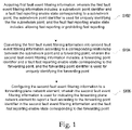
- a filtering information configuration method including: acquiring first fault event filtering information, wherein the first fault event filtering information includes: a subnetwork point identifier and a fault fast reporting enable state corresponding to a subnetwork point, the subnetwork point identifier is used for uniquely identifying the subnetwork point, and the fault fast reporting enable state includes: allowing fast reporting or prohibiting fast reporting; converting the first fault event filtering information into second fault event filtering information according to a corresponding relationship between the subnetwork point and a forwarding point, wherein the second fault event filtering information includes: a forwarding point identifier and a fault fast reporting enable state corresponding to the forwarding point, and the forwarding point identifier is used for uniquely identifying the forwarding point; and configuring the second fault event filtering information to a forwarding plane network element, wherein the second fault event filtering information is used for indicating the forwarding plane network element to report a fault according to the forwarding point identifier in the second fault event
- a filtering information configuration method including: acquiring first fault event filtering information, wherein the first fault event filtering information includes: a subnetwork point identifier and a fault fast reporting enable state corresponding to a subnetwork point, the subnetwork point identifier is used for uniquely identifying the subnetwork point, and the fault fast reporting enable state includes: allowing fast reporting or prohibiting fast reporting; generating third fault event filtering information according to the first fault event filtering information, wherein the third fault event filtering information is used for integrating the first fault event filtering information, and the third fault event filtering information includes: the subnetwork point identifier and the fault fast reporting enable state corresponding to the subnetwork point; converting the third fault event filtering information into second fault event filtering information according to a corresponding relationship between the subnetwork point and a forwarding point, wherein the second fault event filtering information includes: a forwarding point identifier and a fault fast reporting enable state corresponding to the forwarding point, and the
- a filtering information configuration apparatus including: a first acquisition module, configured to acquire first fault event filtering information, wherein the first fault event filtering information includes: a subnetwork point identifier and a fault fast reporting enable state corresponding to a subnetwork point, the subnetwork point identifier is used for uniquely identifying the subnetwork point, and the fault fast reporting enable state includes: allowing fast reporting or prohibiting fast reporting; a first conversion module, configured to convert the first fault event filtering information into second fault event filtering information according to a corresponding relationship between the subnetwork point and a forwarding point, wherein the second fault event filtering information includes: a forwarding point identifier and a fault fast reporting enable state corresponding to the forwarding point, and the forwarding point identifier is used for uniquely identifying the forwarding point; and a first configuration module, configured to configure the second fault event filtering information to a forwarding plane network element, wherein the second fault event filtering information is used for indicating the forwarding
- a filtering information configuration apparatus including: a second acquisition module, configured to acquire first fault event filtering information, wherein the first fault event filtering information includes: a subnetwork point identifier and a fault fast reporting enable state corresponding to a subnetwork point, the subnetwork point identifier is used for uniquely identifying the subnetwork point, and the fault fast reporting enable state includes: allowing fast reporting or prohibiting fast reporting; a generation module, configured to generate third fault event filtering information according to the first fault event filtering information, wherein the third fault event filtering information is used for integrating the first fault event filtering information, and the third fault event filtering information includes: the subnetwork point identifier and the fault fast reporting enable state corresponding to the subnetwork point; a second conversion module, configured to convert the third fault event filtering information into second fault event filtering information according to a corresponding relationship between the subnetwork point and a forwarding point, wherein the second fault event filtering information includes: a forwarding point
- a filtering information configuration system including: a link resources manager module, configured to acquire first fault event filtering information, wherein the first fault event filtering information includes: a subnetwork point identifier and a fault fast reporting enable state corresponding to a subnetwork point, the subnetwork point identifier is used for uniquely identifying the subnetwork point, and the fault fast reporting enable state includes: allowing fast reporting or prohibiting fast reporting; a termination and adaptation execution module, configured to acquire a corresponding relationship between the subnetwork point and a forwarding point, and convert the first fault event filtering information into second fault event filtering information according to the corresponding relationship between the subnetwork point and the forwarding point, wherein the second fault event filtering information includes: a forwarding point identifier and a fault fast reporting enable state corresponding to the forwarding point, and the forwarding point identifier is used for uniquely identifying the forwarding point; and the termination and adaptation execution module is further configured to configure the second fault event filtering information to a
- a filtering information configuration system including: a link resources manager module, configured to acquire first fault event filtering information, wherein the first fault event filtering information includes: a subnetwork point identifier and a fault fast reporting enable state corresponding to a subnetwork point, the subnetwork point identifier is used for uniquely identifying the subnetwork point, and the fault fast reporting enable state includes: allowing fast reporting or prohibiting fast reporting; a resource notification module, configured to generate third fault event filtering information according to the first fault event filtering information, wherein the third fault event filtering information is used for integrating the first fault event filtering information, and the third fault event filtering information includes: the subnetwork point identifier and the fault fast reporting enable state corresponding to the subnetwork point; a termination and adaptation execution module, configured to convert the third fault event filtering information into second fault event filtering information according to a corresponding relationship between the subnetwork point and a forwarding point, wherein the second fault event filtering information includes: a
- a computer-readable storage medium in which a computer program is stored, wherein the computer program is configured to execute the steps in any of the above filtering information configuration method embodiments when running.
- an electronic apparatus including a memory, a processor, and a computer program stored on the memory and capable of running on the processor, wherein the above processor executes the steps in any of the above filtering information configuration method embodiments by means of the computer program.
- the acquired first fault event filtering information is converted into the second fault event filtering information in combination with the corresponding relationship between the subnetwork point and the forwarding point, and the second fault event filtering information including the forwarding point identifier and the fault fast reporting enable state is configured to the forwarding plane network element, so that the forwarding plane network element can determine whether to report a fault event rapidly according to the second fault event filtering information.
- FIG. 1 is a flow diagram of an optional filtering information configuration method in the embodiment of the present invention. As shown in Fig. 1 , the method includes:
- the acquired first fault event filtering information is converted into the second fault event filtering information in combination with the corresponding relationship between the subnetwork point and the forwarding point, and the second fault event filtering information including the forwarding point identifier and the fault fast reporting enable state is configured to the forwarding plane network element, so that the forwarding plane network element may determine whether to report a fault event rapidly according to the second fault event filtering information.
- the forwarding point (Forwarding Point, referred to as FP) involved in the embodiment of the present invention represents a resource in the forwarding plane network element or the forwarding node, which may include a forwarding end point (Forwarding end Point, referred to as FwEP), wherein FwEP represents a forwarding point related to a source or sink of path termination.
- the MCC system may include a software defined network (Software Defined Network, referred to as SDN) controller, a network element management system (Network Element Management System, referred to as EMS), a network management system (Network Management System, referred to as NMS), and a control plane.
- a functional module in the MCC system provides functional services through an interface.
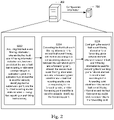
- Fig. 2 is a schematic diagram of a hardware environment of a filtering information configuration method according to an embodiment of the present invention.
- the filtering information configuration method may be applied to the hardware environment formed by a server 202 and a forwarding plane network element 204 as shown in Fig. 2 .
- An executive body of various steps shown in Fig. 1 may be, but is not limited to, the server 202.
- the server 202 converts the acquired first fault event filtering information into the second fault event filtering information, and then configures the second fault event filtering information to the forwarding plane network element 204.
- the above server 202 and the forwarding plane network element 204 may, but are not limited to, implement data interaction through a network, and the above network may include, but is not limited to, a wireless network or a wired network, wherein the wireless network includes: Bluetooth, WIFI and other networks that realize wireless communication.
- the above wired network may include, but is not limited to: a wide area network, a metropolitan area network, and a local area network. The above description is only an example, and this is not limited in any way in the present embodiment.
- the processing steps in the server 202 include:
- Fig. 3 is a schematic structural diagram of an optional MCC system according to an embodiment of the present invention. As shown in Fig. 3, Fig. 3 shows the relationship among a link resources manager (Link Resources Manager, referred to as LRM) module, a termination and adaptation performer (Termination and Adaptation Performer, referred to as TAP) module, a resource notification (Resource Notification, referred to as RN) module and the forwarding plane network element.
- LRM Link Resources Manager
- TAP Termination and Adaptation Performer
- RN resource notification
- forwarding plane network element the forwarding plane network element.
- a specific fault type can be filtered by setting the fault event filtering information, and is rapidly reported to the MCC system without fault confirmation, thereby accelerating the connection recovery.
- the resource (such as a time slot and a bandwidth) of the forwarding plane needs to be converted into a resource that may can be managed and controlled in the MCC system.
- the resource of the forwarding plane is represented by the forwarding point FP or the forwarding end point FwEP, and the resource used by the MCC system is represented by a subnetwork point (Subnetwork Point, referred to as SNP).
- SNP subnetwork Point
- the relationship between FP/FwEP and SNP is managed by the TAP module, one SNP may be bound to one FP/FwEP, and multiple SNPs may also be bound to one FP/FwEP, so as to indicate that the multiple SNPs share the FP/FwEP resource.
- a connection maintained by the MCC system uses a series of SNPs from the management perspective; and from the perspective of the forwarding plane, it uses the FP/FwEP resource in the forwarding plane network element.
- a fault reporting management (FRM) module is an important function in the forwarding plane network element specified in ITU-T G.7710, and it mainly registers faults generated in the network element and rapidly reports faults that need to be reported to a specific MCC system according to the fault event filtering information, such as an SDN controller or a control plane.
- step S202 may be implemented by the LRM module, and the above steps S204 to S208 may be implemented by the TAP module.
- the first fault event filtering information acquired in step S202 may be generated by the LRM module, and may also be received from other external network systems, for example, from the network management system EMS/NMS.
- step S206 may be implemented by the following steps:
- the identifier/position of the forwarding point is intended to uniquely locate the forwarding point in the network layer
- the fault causes corresponding to the same forwarding point may be different, when the same forwarding point corresponds to different subnetwork points, the fault fast reporting enable states of the forwarding point may also be different, and the fault fast reporting enable state of the forwarding point is determined according to the fault fast reporting enable state of the corresponding subnetwork point.
- the position of the forwarding point may be an input side of the forwarding plane network element, or an output side of the forwarding plane network element, or other positions in the network layer, which is not limited in the embodiment of the present invention.
- the fault cause corresponding to the forwarding point may be signal failure, or signal degradation, or possible fault causes of any other forwarding points or forwarding end points.
- the first fault event filtering information contains the subnetwork point identifier and the fault fast reporting enable state corresponding to the subnetwork point, in combination with the corresponding relationship (which may be a mapping relationship table) between the subnetwork point and the forwarding point, the forwarding point corresponding to the subnetwork point is determined, then the identifier/position and the fault cause of the forwarding point are determined according to the forwarding feature parameters of the forwarding point, the fault fast reporting enable state of the corresponding forwarding point is then determined according to the fault fast reporting enable state of the subnetwork point, in this way, the identifier/position, the fault cause and the fault fast reporting enable state of the forwarding point are all set correspondingly, the second fault event filtering information is generated and is configured to the forwarding plane network element, after receiving the fault event, the forwarding plane network element firstly determines a port where the fault occurs, that is, determines the identifier/position of the forwarding point, then finds the fault cause, and then judges whether to allow or prohibit fast reporting according to the corresponding fault
- the forwarding plane network element directly reports the fault event to the MCC system or other management systems without waiting for fault confirmation, so as to request for connection recovery, and if the fault fast reporting enable state shows that fast reporting is prohibited, the forwarding plane network element waits for fault confirmation, and then reports the fault event to the MCC system or other management systems.
- the second fault event filtering information may further include: a state of the fault, wherein the state of the fault includes one of the following: a generation state and a disappearance state.
- a state of the fault wherein the state of the fault includes one of the following: a generation state and a disappearance state.
- the fault fast reporting enable state of the forwarding point may be determined by the following steps:
- the converting the first fault event filtering information into the second fault event filtering information according to the corresponding relationship between the subnetwork point and the forwarding point includes:
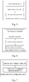
- Fig. 4 is a flow diagram of another optional filtering information configuration method in an embodiment of the present invention. As shown in Fig. 4 , the method includes:
- the first fault event filtering information is generated or received by the LRM module, before being converted into the second fault event filtering information
- the third fault event filtering information may be generated by the RN module according to the first fault event filtering information
- the main function of the RN module is to integrate and manage various signaling messages or configuration messages, it may integrate the subnetwork point identifier and the fault fast reporting enable state contained in the first fault event filtering information into the third fault event filtering information, and then send the same to the TAP module, and the TAP module converts the third fault event filtering information into the second fault event filtering information.
- converting the third fault event filtering information into the second fault event filtering information according to the corresponding relationship between the subnetwork point and the forwarding point includes: acquiring forwarding feature parameters of the forwarding point, wherein the forwarding feature parameters at least include: the forwarding point identifier, the position of the forwarding point in a network layer, and a fault cause corresponding to the forwarding point; and converting the third fault event filtering information into the second fault event filtering information according to the forwarding feature parameters of the forwarding point and the corresponding relationship between the subnetwork point and the forwarding point, wherein the second fault event filtering information at least further includes: the position of the forwarding point in the network layer, the fault cause corresponding to the forwarding point, and a state of the fault.
- converting the third fault event filtering information into the second fault event filtering information according to the corresponding relationship between the subnetwork point and the forwarding point includes: determining, according to the corresponding relationship between the subnetwork point and the forwarding point, the forwarding point corresponding to a first subnetwork point as a first forwarding point; when the fault fast reporting enable state corresponding to the first subnetwork point is allowing fast reporting, determining the fault fast reporting enable state corresponding to the first forwarding point as allowing fast reporting; and when the fault fast reporting enable state corresponding to the first subnetwork point is prohibiting fast reporting, determining, according to a type of the corresponding relationship between the first subnetwork point and the first forwarding point, the fault fast reporting enable state corresponding to the first forwarding point, wherein the type of the corresponding relationship includes: a one-to-one type or a many-to-one type.
- determining, according to the type of the corresponding relationship between the first subnetwork point and the first forwarding point, the fault fast reporting enable state corresponding to the first forwarding point includes: when the type of the corresponding relationship between the first subnetwork point and the first forwarding point is the one-to-one type, determining the fault fast reporting enable state corresponding to the first forwarding point as prohibiting fast reporting; and when the type of the corresponding relationship between the first subnetwork point and the first forwarding point is the many-to-one type, judging the fault fast reporting enable states corresponding to other subnetwork points that have a corresponding relationship with the first forwarding point, when the fault fast reporting enable states corresponding to the other subnetwork points are all prohibiting fast reporting, determining the fault fast reporting enable state corresponding to the first forwarding point as prohibiting fast reporting, and when the fault fast reporting enable state corresponding to any subnetwork point among the other subnetwork points is allowing fast reporting,
- the first fault event filtering information generated or received by the LRM module represents the fault fast reporting enable state configured to one or more subnetwork points, and the enable state of each subnetwork point includes allowing or prohibiting.
- the first fault event filtering information may include one or more records, and each record at least includes: the subnetwork point identifier and the fault fast reporting enable state.
- the third fault event filtering information represents the fault fast reporting enable state configured to one or more subnetwork points, and the enable state configured to each subnetwork point includes allowing or prohibiting.
- the third fault event filtering information may include one or more records, and each record at least includes: a subnetwork point configuration identifier and the fault fast reporting enable state.
- the subnetwork point configuration identifier in the first fault event filtering information is equivalently converted into the subnetwork point configuration identifier in the third fault event filtering information
- the fault fast reporting enable state in the first fault event filtering information is equivalently converted into the fault fast reporting enable state in the third fault event filtering information.
- the second fault event filtering information represents the fault fast reporting enable state configured to one or more forwarding points, and the enable state of each forwarding point includes allowing or prohibiting.
- the second fault event filtering information may include one or more records, and each record at least includes: the identifier/position of the forwarding point, the fault cause and the fault fast reporting enable state.
- the record may further include a generation state or disappearance state of the fault.
- the subnetwork point identifier in the third fault event filtering information is converted into the identifier/position of the forwarding point in the second fault event filtering information through a binding relationship;
- the identifier/position of the forwarding point may further include information about the forwarding point being located on an input side or an output side of the network element.
- the embodiments of the present invention further provide a filtering information configuration apparatus, which is used for implementing the embodiments and preferred implementations of the above filtering information configuration method, and those that have been described will not be repeated.
- the term "module” may implement a combination of software and/or hardware with predetermined functions.
- the apparatus described in the following embodiments is preferably implemented by software, the implementation by hardware or the combination of software and hardware is also possible and conceived.
- the method according to the above embodiments may be implemented by software plus a necessary general hardware platform, of course, it may also be implemented by hardware, but the former is a better implementation in many cases.
- the technical solutions of the present invention substantially, or a part contributing to the prior art may be implemented in the form of a software product, the computer software product is stored in a storage medium (such as an ROM/RAM, a magnetic disk, and an optical disk), and includes a plurality of instructions for enabling a terminal device (which may be a mobile phone, a computer, a server, or a network device or the like) to execute the method described in various embodiments of the present invention.
- the embodiments of the present invention further provide a filtering information configuration apparatus, which is used for implementing the embodiments and preferred implementations of the above filtering information configuration method, and those that have been described will not be repeated.
- the term "module” may implement a combination of software and/or hardware with predetermined functions.
- the apparatus described in the following embodiments is preferably implemented by software, the implementation by hardware or the combination of software and hardware is also possible and conceived.
- Fig. 5 is a structural block diagram of an optional filtering information configuration apparatus according to an embodiment of the present invention. As shown in Fig. 5 , the apparatus includes:
- Fig. 6 is a structural block diagram of another optional filtering information configuration apparatus according to an embodiment of the present invention. As shown in Fig. 6 , the apparatus includes:
- the embodiments of the present invention further provide a filtering information configuration system, the apparatus is used for implementing the embodiments and preferred implementations of the above filtering information configuration method, and those that have been described will not be repeated.
- the term "module” may implement a combination of software and/or hardware with predetermined functions.
- the apparatus described in the following embodiments is preferably implemented by software, the implementation by hardware or the combination of software and hardware is also possible and conceived
- Fig. 7 is a structural block diagram of an optional filtering information configuration system according to an embodiment of the present invention. As shown in Fig. 7 , the system includes:
- the TAP module includes:
- the TAP module further includes:
- the third determining unit includes:
- Fig. 8 is a structural block diagram of another optional filtering information configuration system according to an embodiment of the present invention. As shown in Fig. 8 , the system includes:
- the termination and adaptation execution module 806 includes:
- the termination and adaptation execution module 806 further includes:
- the sixth determining unit includes:
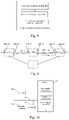
- Fig. 9 is a topological structure diagram of an optional forwarding plane network element according to an embodiment of the present invention.
- the forwarding plane network elements are interconnected by optical transport unit OTU2 links.
- an optical data unit ODU1 connection between a 8# port of a point A point and the 8# port of a point Z may be established through an MCC system, such as an SDN controller or a control plane.
- No tandem connection monitor (Tandem Connection Monitor, referred to as TCM) related fault monitoring is configured in the topological structure shown in Fig. 6 .
- Table 1 shows a binding relationship between a forwarding plane resource, that is, a subnetwork point (Subnetwork Point, referred to as SNP), used by the connection and FP/FwEP.
- SNP subnetwork Point
- Table 1 SNP identifier Bound FP resource SNP-A8 1#ODU1 of 8#OTU2 port of network element A SNP-A 1 1#ODU1 of 1#OTU2 port of network element A SNP-B1 1#ODU1 of 1#OTU2 port of network element B SNP-B2 1#ODU1 of 2#OTU2 port of network element B SNP-Z1 1#ODU1 of 1#OTU2 port of network element Z SNP-Z8 1#ODU1 of 8#OTU2 port of network element Z
- the MCC system may configure a specific SNP to allow fault reporting or prohibit fault reporting.
- the fault fast reporting enable states of all the SNPs used by the connection are set to allow, that is, the fault of the forwarding plane resource used by the connection may be rapidly reported to the MCC system through FRM.
- the filtering information configuration method provided by the embodiment of the present invention may include the following steps: Step A: an LRM generates or receives first fault event filtering information.
- the first fault event filtering information generated by the LRM includes 6 fault event filtering information records, and each record at least includes: an SNP identifier and a fault fast reporting enable state. All records are as follows: SNP identifier Fault fast reporting enable state SNP-A8 Allow SNP-A 1 Allow SNP-B1 Allow SNP-B2 Allow SNP-Z1 Allow SNP-Z8 Allow
- the first fault event filtering information may also come from other configurations, such as a network management system EMS/NMS, and other components in the MCC system, such as a CC.
- EMS/NMS network management system
- CC CC
- Step B the LRM transmits the first fault event filtering information to a TAP.
- Step C the TAP module converts the first fault event filtering information into second fault event filtering information according to a binding relationship between a subnetwork point and a forwarding point, and forwarding technical features of the forwarding point or a forwarding end point.
- each FP is only bound to one SNP, and correspondingly, 6 SNPs correspond to 6 FPs.
- the second fault event filtering information may include multiple records, and each record at least includes: FP identifier and position, a fault cause, and a fault fast reporting enable state.
- the FP identifier and position, and one or more fault causes that may trigger connection recovery will be learned.
- FP (1#ODU1 of 1#OTU2 port of network element B) is located in the 1#ODU1 of the 1#OTU2 port of the network element B. It can be further seen that, the FP is located on an input side of the network element.
- the fault causes that may trigger connection recovery include: ODU-AIS, ODU-OCI, ODU-LCK, ODU-LOF, and so on. Other FPs are processed similarly.
- each record at least includes: the FP identifier and position, the fault cause, and the fault fast reporting enable state. It may further include a fault generation or disappearance state. Therefore, the format of the second fault event filtering information format is as follows: FP Fault cause Fault generation or disappearance state Fault fast reporting enable state
- the first fault event filtering information is converted into the second fault event filtering information, and the conversion process of the fault fast reporting enable state includes: each record in the first fault event filtering information is judged and processed as follows: if the fault fast reporting enable state of the SNP in the record of the first fault event filtering information is "Allow", when being converted into the second fault event filtering information, in the record of the second fault event filtering information, the fault fast reporting enable states in all the records of the FP bound to the SNP are set to "Allow".
- the fault fast reporting enable states in the generated second fault event filtering information are all "Allow”. That is, the converted second fault event filtering information is as follows: FP (related to network element A) Fault cause Fault fast reporting enable state 1#ODU1 of 8#port of network element A ODU-AIS Allow 1#ODU1 of 8#port of network element A ODU-OCI Allow 1#ODU1 of 8#port of network element A ODU-LCK Allow 1#ODU1 of 8#port of network element A ODU-LOF Allow 1#ODU1 of 1#port of network element A ODU-AIS Allow 1#ODU1 of 1#port of network element A ODU-OCI Allow 1#ODU1 of 1#port of network element A ODU-LCK Allow FP (related to network element B) Fault cause Fault fast reporting enable state 1#ODU1 of 1#port of network element B ODU-AIS Allow 1#ODU1 of 1#port of network element
- Step D the TAP configures the second fault event filtering information to forwarding plane network elements A, B and Z.
- each network element only needs to receive the record of the second fault event filtering information of the own network element.
- Example 1 On the basis of Example 1, after the ODU1 connection is deleted, the configured fault event filtering information is canceled, that is, the fault fast reporting enable state in the first fault event filtering information is set to "Prohibit".
- Step A an LRM generates or receives first fault event filtering information.
- the first fault event filtering information generated by the LRM includes 6 fault event filtering information records, and each record at least includes: an SNP identifier and a fault fast reporting enable state. All records are as follows: SNP identifier Fault fast reporting enable state SNP-A8 Prohibit SNP-A 1 Prohibit SNP-B1 Prohibit SNP-B2 Prohibit SNP-Z1 Prohibit SNP-Z8 Prohibit
- the first fault event filtering information may also come from other configurations, such as a network management system EMS/NMS, and other components in the MCC system, such as a CC.
- EMS/NMS network management system
- CC CC
- Step B the LRM transmits the first fault event filtering information to a TAP.
- Step C the TAP converts the first fault event filtering information into second fault event filtering information according to a binding relationship between an SNP and an FP, and forwarding technical features of the FP.
- the binding relationship is shown in Table 1, each FP is only bound to one SNP, and correspondingly, 6 SNPs correspond to 6 FPs.
- the second fault event filtering information may include multiple records, and each record at least includes: FP identifier and position, a fault cause, and a fault fast reporting enable state.
- the FP identifier and position, and one or more fault causes that may trigger connection recovery will be learned.
- FP (1#ODU1 of 1#OTU2 port of network element B) is located in the 1#ODU1 of the 1#OTU2 port of the network element B. It can be further seen that, the FP is located on an input side of the network element.
- the fault causes that may trigger connection recovery include: ODU-AIS, ODU-OCI, ODU-LCK, ODU-LOF, and so on. Other FPs are processed similarly.
- each record at least includes: the FP identifier and position, the fault cause, and the fault fast reporting enable state. It may further include a fault generation or disappearance state. Therefore, the format of the second fault event filtering information format is as follows: FP Fault cause Fault generation or disappearance state Fault fast reporting enable state
- the first fault event filtering information is converted into the second fault event filtering information, and the conversion process of the fault fast reporting enable state includes: each record in the first fault event filtering information is judged and processed as follows: if the fault fast reporting enable state of the SNP in the record of the first fault event filtering information is Prohibit, when being converted into the second fault event filtering information, in the record of the second fault event filtering information: if the SNP and the FP are bound in a one-to-one manner, all the fault fast reporting enable states of the FP bound to the SNP are set as "Prohibit"; if the SNP and the FP are not bound in the one-to-one manner, it means that the FP bound to the SNP is also bound to other SNPs, at this time, the fault fast reporting enable states of these "other SNPs" need to be checked, and the fault fast reporting enable state of the FP is determined accordingly: if the fault fast reporting enable state in the first fault event filtering information corresponding to at least one SNP among these "other
- the converted second fault event filtering information is as follows: FP (related to network element A) Fault cause Fault fast reporting enable state 1#ODU1 of 8#port of network element A ODU-AIS Prohibit 1#ODU1 of 8#port of network element A ODU-OCI Prohibit 1#ODU1 of 8#port of network element A ODU-LCK Prohibit 1#ODU1 of 8#port of network element A ODU-LOF Prohibit 1#ODU1 of 1#port of network element A ODU-AIS Prohibit 1#ODU1 of 1#port of network element A ODU-OCI Prohibit 1#ODU1 of 1#port of network element A ODU-LCK Prohibit FP (related to network element B) Fault cause Fault fast reporting enable state 1#ODU1 of 1#port of network element B ODU-AIS Prohibit 1#ODU1 of 1#port of network element B ODU-OCI Prohibit 1#ODU1 of 1#port of network element B ODU-LCK
- Step D the TAP configures the second fault event filtering information to forwarding plane network elements A, B and Z.
- each network element only needs to receive the record of the second fault event filtering information of the own network element.
- a topology composed of four network elements ABCZ the network elements are interconnected by OTU2 links.
- an ODU1 connection between a 8# port of a point A point and the 8# port of a point Z may be established through an MCC system, such as an SDN controller or a control plane.
- MCC system such as an SDN controller or a control plane.
- No TCM related fault monitoring is configured.
- Table 1 shows a binding relationship between a forwarding plane resource, that is, an SNP, used by the connection and an FP.
- the MCC system may configure a specific SNP to allow fault reporting or prohibit fault reporting.
- the fault fast reporting enable states of all the SNPs used by the connection are set to allow, that is, the fault of the forwarding plane resource used by the connection may be rapidly reported to the MCC system through FRM.
- Step A an LRM generates or receives first fault event filtering information.
- the first fault event filtering information generated by the LRM includes 6 fault event filtering information records, and each record at least includes: an SNP identifier and a fault fast reporting enable state. All records are as follows: SNP identifier Fault fast reporting enable state SNP-A8 Allow SNP-A 1 Allow SNP-B1 Allow SNP-B2 Allow SNP-Z1 Allow SNP-Z8 Allow
- Step B the LRM transmits the first fault event filtering information to an RN module.
- Step C the RN module converts the first fault event filtering information into third fault event filtering information; a subnetwork point configuration identifier in the first fault event filtering information is equivalently converted into the subnetwork point configuration identifier in the third fault event filtering information, and the fault fast reporting enable state in the first fault event filtering information is equivalently converted into the fault fast reporting enable state in the third fault event filtering information.
- Step D the RN module transmits the third fault event filtering information to a TAP module.
- the RN module may store the first fault event filtering information and the third fault event filtering information.
- Step E the TAP converts the third fault event filtering information into second fault event filtering information according to the binding relationship between the SNP and the FP and forwarding technical features of the FP.
- the binding relationship is show in Table, each FP is only bound to one SNP, and correspondingly, 6 SNPs correspond to 6 FPs.
- the second fault event filtering information may include multiple records, and each record at least includes: FP identifier and position, a fault cause, and a fault fast reporting enable state.
- the FP identifier and position, and one or more fault causes that may trigger connection recovery will be learned.
- FP (1#ODU1 of 1#OTU2 port of network element B) is located in the 1#ODU1 of the 1#OTU2 port of the network element B. It can be further seen that, the FP is located on an input side of the network element.
- the fault causes that may trigger connection recovery include: ODU-AIS, ODU-OCI, ODU-LCK, ODU-LOF, and so on. Other FPs are processed similarly.
- each record at least includes: the FP identifier and position, the fault cause, and the fault fast reporting enable state. It may further include a fault generation or disappearance state. Therefore, the format of the second fault event filtering FP Fault cause Fault generation or disappearance state Fault fast reporting enable state information format is as follows: The first fault event filtering information is converted into the second fault event filtering information, and the conversion process of the fault fast reporting enable state includes: each record in the first fault event filtering information is judged and processed as follows: if the fault fast reporting enable state of the SNP in the record of the first fault event filtering information is "Allow", when being converted into the second fault event filtering information, in the record of the second fault event filtering information, the fault fast reporting enable states in all the records of the FP bound to the SNP are set to "Allow".
- the fault fast reporting enable states in the generated second fault event filtering information are all "Allow”. That is, the converted second fault event filtering information is as follows: FP (related to network element A) Fault cause Fault fast reporting enable state 1#ODU1 of 8#port of network element A ODU-AIS Allow 1#ODU1 of 8#port of network element A ODU-OCI Allow 1#ODU1 of 8#port of network element A ODU-LCK Allow 1#ODU1 of 8#port of network element A ODU-LOF Allow 1#ODU1 of 1#port of network element A ODU-AIS Allow 1#ODU1 of 1#port of network element A ODU-OCI Allow 1#ODU1 of 1#port of network element A ODU-LCK Allow FP (related to network element B) Fault cause Fault fast reporting enable state 1#ODU1 of 1#port of network element B ODU-AIS Allow 1#ODU1 of 1#port of network element
- Step F the TAP configures the second fault event filtering information to forwarding plane network elements A, B and Z.
- each network element only needs to receive the record of the second fault event filtering information of the own network element.
- an electronic apparatus for implementing the above method for updating a knowledge graph is further provided.
- the electronic apparatus includes a memory 1002 and a processor 1004, a computer program is stored in the memory 1002, and the processor 1004 is configured to execute the steps in any one of the above method embodiments through the computer program.
- the above electronic apparatus may be located in at least one network device among a plurality of network devices in a computer network.
- the above processor may be configured to execute the following steps through the computer program:
- the structure shown in Fig. 10 is only schematic, and the electronic apparatus may also be smart phones (such as an Android mobile phone, and an iOS mobile phone), tablet computers, palmtop computers, mobile Internet devices (Mobile Internet Devices, MID), PADs and other terminal devices.
- Fig. 10 does not limit the structure of the above electronic apparatus.
- the electronic apparatus may further include more or fewer components (such as a network interface) than shown in Fig. 10 , or have a different configuration from that shown in Fig. 10 .
- the memory 1002 may be configured to store software programs and modules, such as program instructions/modules corresponding to the filtering information configuration method and apparatus in the embodiments of the present invention, and the processor 1004, by means of running the software programs and modules stored in the memory 1002, executes various functional applications and data processing, that is, implements the above filtering information configuration method.
- the memory 1002 may include a high-speed random access memory, and may also include a non-volatile memory, such as one or more magnetic storage apparatuses, a flash memory, or other non-volatile solid-state memories.
- the memory 1002 may further include a memory that is remotely provided with respect to the processor 1004, and these remote memories may be connected to a terminal through a network.
- the memory 1002 may be specifically configured to, but is not limited to, store program steps of the method for updating the knowledge graph.
- the memory 1002 may include, but is not limited to, the first acquisition module 502, the first conversion module 504 and the first configuration module 506 in the above filtering information configuration apparatus, and may also include, but is not limited to, the second acquisition module 602, the generation module 604, the second conversion module 606 and the second configuration module 608 in the above filtering information configuration apparatus.
- it may also include, but is not limited to, other module units in the above filtering information configuration apparatus, which will not be repeated in the present example.
- the above transmission apparatus 1006 is configured to receive or send data through a network.
- the above network may include a wired network and a wireless network.
- the transmission apparatus 1006 includes a network interface controller (Network Interface Controller, NIC), which may be connected to other network devices and routers through network cables, so as to communicate with the Internet or the local area network.
- the transmission apparatus 1006 is a radio frequency (Radio Frequency, RF) module, which is configured to communicate with the Internet in a wireless manner.
- RF Radio Frequency
- the above electronic apparatus further includes: a display 1008, configured to display alarm push of a suspicious account number; and a connection bus 1010, configured to connect various module components in the above electronic apparatus.
- the embodiments of the present invention further provide a computer-readable storage medium, in which a computer program is stored, wherein the computer program is configured to execute the steps in any of the above method embodiments when running.
- the above storage medium may be configured to store a computer program that is used for executing the following steps:
- the above storage medium may include, but is not limited to: a USB disk, a read only memory (Read Only Memory, referred to as ROM), a random access memory (Random Access Memory, referred to as RAM), a mobile hard disk, a magnetic disk or an optical disk and other media that may store the computer program.
- ROM Read Only Memory
- RAM Random Access Memory
- mobile hard disk a magnetic disk or an optical disk and other media that may store the computer program.
- modules or steps of the present invention may be implemented by a general computing apparatus, and they may be concentrated on a single computing apparatus, or distributed on a network composed of multiple computing apparatuses.
- they may be implemented by program codes that are executable by the computing apparatus, so that they may be stored in a storage apparatus for execution by the computing apparatus, and in some cases, the shown or described steps may be executed in a different sequence than here, or they are fabricated into integrated circuit modules respectively, or multiple modules or steps therein are fabricated into a single integrated circuit module for implementation.
- the present invention is not limited to any specific combination of hardware and software.
- the filtering information configuration method and system provided by the embodiments of the present invention have the following beneficial effects: the problem in the prior art that the quality of key services is greatly affected by the delayed reporting of fault events is solved, so that the fault events in the MCC system may be reported rapidly and selectively or reported after waiting for fault confirmation, which is conducive to accelerating the fault recovery of the management and control system, and improving the processing quality of the key services.
Landscapes
- Engineering & Computer Science (AREA)
- Computer Networks & Wireless Communication (AREA)
- Signal Processing (AREA)
- Data Exchanges In Wide-Area Networks (AREA)
Applications Claiming Priority (2)
| Application Number | Priority Date | Filing Date | Title |
|---|---|---|---|
| CN201910944545.0A CN112583623B (zh) | 2019-09-30 | 2019-09-30 | 过滤信息配置方法及系统 |
| PCT/CN2020/101943 WO2021063069A1 (zh) | 2019-09-30 | 2020-07-14 | 过滤信息配置方法及系统 |
Publications (3)
| Publication Number | Publication Date |
|---|---|
| EP4040728A1 true EP4040728A1 (de) | 2022-08-10 |
| EP4040728A4 EP4040728A4 (de) | 2022-11-16 |
| EP4040728B1 EP4040728B1 (de) | 2024-12-11 |
Family
ID=75116684
Family Applications (1)
| Application Number | Title | Priority Date | Filing Date |
|---|---|---|---|
| EP20871463.4A Active EP4040728B1 (de) | 2019-09-30 | 2020-07-14 | Verfahren und system für filterinformationskonfiguration |
Country Status (3)
| Country | Link |
|---|---|
| EP (1) | EP4040728B1 (de) |
| CN (1) | CN112583623B (de) |
| WO (1) | WO2021063069A1 (de) |
Cited By (1)
| Publication number | Priority date | Publication date | Assignee | Title |
|---|---|---|---|---|
| US12483470B2 (en) * | 2023-01-24 | 2025-11-25 | Rakuten Symphony, Inc. | Optimal fault management reporting via host level northbound fault reporting agent |
Family Cites Families (11)
| Publication number | Priority date | Publication date | Assignee | Title |
|---|---|---|---|---|
| JP4255366B2 (ja) * | 2003-11-28 | 2009-04-15 | 富士通株式会社 | ネットワーク監視プログラム、ネットワーク監視方法、およびネットワーク監視装置 |
| WO2009129841A1 (en) * | 2008-04-21 | 2009-10-29 | Telefonaktiebolaget L M Ericsson (Publ) | Method and system for network fault management |
| CN110113825A (zh) * | 2012-06-30 | 2019-08-09 | 华为技术有限公司 | 一种控制和转发解耦架构下的转发面隧道资源的管理方法 |
| CN102833108B (zh) * | 2012-08-30 | 2016-03-30 | 华为技术有限公司 | 故障点位置信息处理方法及设备 |
| CN106301828A (zh) * | 2015-05-21 | 2017-01-04 | 中兴通讯股份有限公司 | 一种虚拟化网络功能业务故障的处理方法及装置 |
| CN106487696B (zh) * | 2015-08-28 | 2019-07-23 | 中兴通讯股份有限公司 | 链路故障检测方法及装置 |
| CN105657039A (zh) * | 2016-02-15 | 2016-06-08 | 上海带来科技有限公司 | 一种基于大数据的电厂设备故障快速定位系统和方法 |
| CN105743711B (zh) * | 2016-04-13 | 2019-10-18 | 华为技术有限公司 | 一种网络路径的故障检测方法、装置及网络设备 |
| CN107733672A (zh) * | 2016-08-12 | 2018-02-23 | 南京中兴软件有限责任公司 | 故障处理方法、装置及控制器 |
| WO2018033773A1 (en) * | 2016-08-16 | 2018-02-22 | Telefonaktiebolaget Lm Ericsson (Publ) | Assisted multi-level fast rerouting |
| CN107968747A (zh) * | 2016-10-19 | 2018-04-27 | 中兴通讯股份有限公司 | 一种路径调整管理方法及装置、通信系统 |
-
2019
- 2019-09-30 CN CN201910944545.0A patent/CN112583623B/zh active Active
-
2020
- 2020-07-14 EP EP20871463.4A patent/EP4040728B1/de active Active
- 2020-07-14 WO PCT/CN2020/101943 patent/WO2021063069A1/zh not_active Ceased
Cited By (1)
| Publication number | Priority date | Publication date | Assignee | Title |
|---|---|---|---|---|
| US12483470B2 (en) * | 2023-01-24 | 2025-11-25 | Rakuten Symphony, Inc. | Optimal fault management reporting via host level northbound fault reporting agent |
Also Published As
| Publication number | Publication date |
|---|---|
| EP4040728A4 (de) | 2022-11-16 |
| EP4040728B1 (de) | 2024-12-11 |
| WO2021063069A1 (zh) | 2021-04-08 |
| CN112583623A (zh) | 2021-03-30 |
| CN112583623B (zh) | 2023-02-07 |
Similar Documents
| Publication | Publication Date | Title |
|---|---|---|
| EP4055896B1 (de) | Verfahren und vorrichtungen zum verwalten kompromittierter kommunikationsvorrichtungen in einem kommunikationsnetz | |
| US10374714B2 (en) | Method for online switching of operation mode of ONT, ONT and OLT | |
| US10425281B2 (en) | Automated network entity replacement based on historical topology consciousness | |
| EP3742786A1 (de) | Netzwerkalarmverfahren, vorrichtung, system und endgerät | |
| EP3051750B1 (de) | Sammeladapterverwaltungsverfahren und -system | |
| US9391842B2 (en) | Self-configuring transport network | |
| EP4040728A1 (de) | Verfahren und system für filterinformationskonfiguration | |
| EP3355530A1 (de) | Verfahren, vorrichtung und einrichtung zur verarbeitung von dienstausfällen | |
| CN111344962B (zh) | 光网络单元的网络接口切换方法及光网络单元 | |
| CN104488227A (zh) | 用于在大型数据处理系统中进行孤立异常检测的方法 | |
| CN108667640B (zh) | 通信方法及设备、网络接入系统 | |
| JP4673532B2 (ja) | マルチマネージャ環境における包括アライメントプロセス | |
| EP3139536A1 (de) | Alarmmeldeverfahren und -vorrichtung | |
| CN112583622A (zh) | 故障事件信息的上报方法及系统 | |
| CN101345590A (zh) | Sncp业务配置方法 | |
| CN113300862B (zh) | 一种告警处理方法、装置及设备 | |
| CN105591787A (zh) | 一种网络中的根本原因分析方法、装置和系统 | |
| EP3934133B1 (de) | Verfahren und vorrichtung zur vermittlungswegumschaltung | |
| KR20160025959A (ko) | 소프트웨어 정의 네트워크 시스템 및 오픈플로우 메시지 제어 방법 | |
| CN105306238A (zh) | 终端接入方法、装置和系统 | |
| US20250279930A1 (en) | Multi-protocol open radio access network system | |
| US20240251190A1 (en) | Passive optical network | |
| CN118041718A (zh) | 一种具备防阻塞功能的车机网络通信方法、系统及存储介质 | |
| CN112533082B (zh) | 链路资源发现方法、装置、设备及计算机可读存储介质 | |
| JP6546017B2 (ja) | 通信装置、送信方法、及び、プログラム |
Legal Events
| Date | Code | Title | Description |
|---|---|---|---|
| STAA | Information on the status of an ep patent application or granted ep patent |
Free format text: STATUS: THE INTERNATIONAL PUBLICATION HAS BEEN MADE |
|
| PUAI | Public reference made under article 153(3) epc to a published international application that has entered the european phase |
Free format text: ORIGINAL CODE: 0009012 |
|
| STAA | Information on the status of an ep patent application or granted ep patent |
Free format text: STATUS: REQUEST FOR EXAMINATION WAS MADE |
|
| 17P | Request for examination filed |
Effective date: 20220331 |
|
| AK | Designated contracting states |
Kind code of ref document: A1 Designated state(s): AL AT BE BG CH CY CZ DE DK EE ES FI FR GB GR HR HU IE IS IT LI LT LU LV MC MK MT NL NO PL PT RO RS SE SI SK SM TR |
|
| REG | Reference to a national code |
Ref country code: DE Ref legal event code: R079 Free format text: PREVIOUS MAIN CLASS: H04L0012240000 Ipc: H04L0041060400 Ref country code: DE Ref legal event code: R079 Ref document number: 602020043126 Country of ref document: DE Free format text: PREVIOUS MAIN CLASS: H04L0012240000 Ipc: H04L0041060400 |
|
| A4 | Supplementary search report drawn up and despatched |
Effective date: 20221014 |
|
| RIC1 | Information provided on ipc code assigned before grant |
Ipc: H04L 41/0895 20220101ALI20221010BHEP Ipc: H04L 41/0823 20220101ALI20221010BHEP Ipc: H04L 41/0604 20220101AFI20221010BHEP |
|
| DAV | Request for validation of the european patent (deleted) | ||
| DAX | Request for extension of the european patent (deleted) | ||
| GRAP | Despatch of communication of intention to grant a patent |
Free format text: ORIGINAL CODE: EPIDOSNIGR1 |
|
| STAA | Information on the status of an ep patent application or granted ep patent |
Free format text: STATUS: GRANT OF PATENT IS INTENDED |
|
| INTG | Intention to grant announced |
Effective date: 20240802 |
|
| GRAS | Grant fee paid |
Free format text: ORIGINAL CODE: EPIDOSNIGR3 |
|
| GRAA | (expected) grant |
Free format text: ORIGINAL CODE: 0009210 |
|
| STAA | Information on the status of an ep patent application or granted ep patent |
Free format text: STATUS: THE PATENT HAS BEEN GRANTED |
|
| AK | Designated contracting states |
Kind code of ref document: B1 Designated state(s): AL AT BE BG CH CY CZ DE DK EE ES FI FR GB GR HR HU IE IS IT LI LT LU LV MC MK MT NL NO PL PT RO RS SE SI SK SM TR |
|
| REG | Reference to a national code |
Ref country code: GB Ref legal event code: FG4D |
|
| REG | Reference to a national code |
Ref country code: CH Ref legal event code: EP |
|
| REG | Reference to a national code |
Ref country code: DE Ref legal event code: R096 Ref document number: 602020043126 Country of ref document: DE |
|
| REG | Reference to a national code |
Ref country code: IE Ref legal event code: FG4D |
|
| REG | Reference to a national code |
Ref country code: LT Ref legal event code: MG9D |
|
| PG25 | Lapsed in a contracting state [announced via postgrant information from national office to epo] |
Ref country code: HR Free format text: LAPSE BECAUSE OF FAILURE TO SUBMIT A TRANSLATION OF THE DESCRIPTION OR TO PAY THE FEE WITHIN THE PRESCRIBED TIME-LIMIT Effective date: 20241211 |
|
| PG25 | Lapsed in a contracting state [announced via postgrant information from national office to epo] |
Ref country code: FI Free format text: LAPSE BECAUSE OF FAILURE TO SUBMIT A TRANSLATION OF THE DESCRIPTION OR TO PAY THE FEE WITHIN THE PRESCRIBED TIME-LIMIT Effective date: 20241211 |
|
| PG25 | Lapsed in a contracting state [announced via postgrant information from national office to epo] |
Ref country code: BG Free format text: LAPSE BECAUSE OF FAILURE TO SUBMIT A TRANSLATION OF THE DESCRIPTION OR TO PAY THE FEE WITHIN THE PRESCRIBED TIME-LIMIT Effective date: 20241211 |
|
| REG | Reference to a national code |
Ref country code: NL Ref legal event code: MP Effective date: 20241211 |
|
| PG25 | Lapsed in a contracting state [announced via postgrant information from national office to epo] |
Ref country code: ES Free format text: LAPSE BECAUSE OF FAILURE TO SUBMIT A TRANSLATION OF THE DESCRIPTION OR TO PAY THE FEE WITHIN THE PRESCRIBED TIME-LIMIT Effective date: 20241211 |
|
| PG25 | Lapsed in a contracting state [announced via postgrant information from national office to epo] |
Ref country code: NO Free format text: LAPSE BECAUSE OF FAILURE TO SUBMIT A TRANSLATION OF THE DESCRIPTION OR TO PAY THE FEE WITHIN THE PRESCRIBED TIME-LIMIT Effective date: 20250311 |
|
| PG25 | Lapsed in a contracting state [announced via postgrant information from national office to epo] |
Ref country code: LV Free format text: LAPSE BECAUSE OF FAILURE TO SUBMIT A TRANSLATION OF THE DESCRIPTION OR TO PAY THE FEE WITHIN THE PRESCRIBED TIME-LIMIT Effective date: 20241211 Ref country code: GR Free format text: LAPSE BECAUSE OF FAILURE TO SUBMIT A TRANSLATION OF THE DESCRIPTION OR TO PAY THE FEE WITHIN THE PRESCRIBED TIME-LIMIT Effective date: 20250312 |
|
| PG25 | Lapsed in a contracting state [announced via postgrant information from national office to epo] |
Ref country code: RS Free format text: LAPSE BECAUSE OF FAILURE TO SUBMIT A TRANSLATION OF THE DESCRIPTION OR TO PAY THE FEE WITHIN THE PRESCRIBED TIME-LIMIT Effective date: 20250311 |
|
| PG25 | Lapsed in a contracting state [announced via postgrant information from national office to epo] |
Ref country code: NL Free format text: LAPSE BECAUSE OF FAILURE TO SUBMIT A TRANSLATION OF THE DESCRIPTION OR TO PAY THE FEE WITHIN THE PRESCRIBED TIME-LIMIT Effective date: 20241211 |
|
| REG | Reference to a national code |
Ref country code: AT Ref legal event code: MK05 Ref document number: 1751244 Country of ref document: AT Kind code of ref document: T Effective date: 20241211 |
|
| PG25 | Lapsed in a contracting state [announced via postgrant information from national office to epo] |
Ref country code: SM Free format text: LAPSE BECAUSE OF FAILURE TO SUBMIT A TRANSLATION OF THE DESCRIPTION OR TO PAY THE FEE WITHIN THE PRESCRIBED TIME-LIMIT Effective date: 20241211 |
|
| PG25 | Lapsed in a contracting state [announced via postgrant information from national office to epo] |
Ref country code: PL Free format text: LAPSE BECAUSE OF FAILURE TO SUBMIT A TRANSLATION OF THE DESCRIPTION OR TO PAY THE FEE WITHIN THE PRESCRIBED TIME-LIMIT Effective date: 20241211 |
|
| PG25 | Lapsed in a contracting state [announced via postgrant information from national office to epo] |
Ref country code: IS Free format text: LAPSE BECAUSE OF FAILURE TO SUBMIT A TRANSLATION OF THE DESCRIPTION OR TO PAY THE FEE WITHIN THE PRESCRIBED TIME-LIMIT Effective date: 20250411 |
|
| PG25 | Lapsed in a contracting state [announced via postgrant information from national office to epo] |
Ref country code: PT Free format text: LAPSE BECAUSE OF FAILURE TO SUBMIT A TRANSLATION OF THE DESCRIPTION OR TO PAY THE FEE WITHIN THE PRESCRIBED TIME-LIMIT Effective date: 20250411 |
|
| PG25 | Lapsed in a contracting state [announced via postgrant information from national office to epo] |
Ref country code: EE Free format text: LAPSE BECAUSE OF FAILURE TO SUBMIT A TRANSLATION OF THE DESCRIPTION OR TO PAY THE FEE WITHIN THE PRESCRIBED TIME-LIMIT Effective date: 20241211 |
|
| PG25 | Lapsed in a contracting state [announced via postgrant information from national office to epo] |
Ref country code: RO Free format text: LAPSE BECAUSE OF FAILURE TO SUBMIT A TRANSLATION OF THE DESCRIPTION OR TO PAY THE FEE WITHIN THE PRESCRIBED TIME-LIMIT Effective date: 20241211 Ref country code: AT Free format text: LAPSE BECAUSE OF FAILURE TO SUBMIT A TRANSLATION OF THE DESCRIPTION OR TO PAY THE FEE WITHIN THE PRESCRIBED TIME-LIMIT Effective date: 20241211 |
|
| PG25 | Lapsed in a contracting state [announced via postgrant information from national office to epo] |
Ref country code: SK Free format text: LAPSE BECAUSE OF FAILURE TO SUBMIT A TRANSLATION OF THE DESCRIPTION OR TO PAY THE FEE WITHIN THE PRESCRIBED TIME-LIMIT Effective date: 20241211 |
|
| PG25 | Lapsed in a contracting state [announced via postgrant information from national office to epo] |
Ref country code: CZ Free format text: LAPSE BECAUSE OF FAILURE TO SUBMIT A TRANSLATION OF THE DESCRIPTION OR TO PAY THE FEE WITHIN THE PRESCRIBED TIME-LIMIT Effective date: 20241211 |
|
| PG25 | Lapsed in a contracting state [announced via postgrant information from national office to epo] |
Ref country code: IT Free format text: LAPSE BECAUSE OF FAILURE TO SUBMIT A TRANSLATION OF THE DESCRIPTION OR TO PAY THE FEE WITHIN THE PRESCRIBED TIME-LIMIT Effective date: 20241211 |
|
| PG25 | Lapsed in a contracting state [announced via postgrant information from national office to epo] |
Ref country code: SE Free format text: LAPSE BECAUSE OF FAILURE TO SUBMIT A TRANSLATION OF THE DESCRIPTION OR TO PAY THE FEE WITHIN THE PRESCRIBED TIME-LIMIT Effective date: 20241211 |
|
| REG | Reference to a national code |
Ref country code: DE Ref legal event code: R097 Ref document number: 602020043126 Country of ref document: DE |
|
| PG25 | Lapsed in a contracting state [announced via postgrant information from national office to epo] |
Ref country code: DK Free format text: LAPSE BECAUSE OF FAILURE TO SUBMIT A TRANSLATION OF THE DESCRIPTION OR TO PAY THE FEE WITHIN THE PRESCRIBED TIME-LIMIT Effective date: 20241211 |
|
| PGFP | Annual fee paid to national office [announced via postgrant information from national office to epo] |
Ref country code: DE Payment date: 20250722 Year of fee payment: 6 |
|
| PGFP | Annual fee paid to national office [announced via postgrant information from national office to epo] |
Ref country code: GB Payment date: 20250724 Year of fee payment: 6 |
|
| PLBE | No opposition filed within time limit |
Free format text: ORIGINAL CODE: 0009261 |
|
| STAA | Information on the status of an ep patent application or granted ep patent |
Free format text: STATUS: NO OPPOSITION FILED WITHIN TIME LIMIT |
|
| PGFP | Annual fee paid to national office [announced via postgrant information from national office to epo] |
Ref country code: FR Payment date: 20250725 Year of fee payment: 6 |
|
| REG | Reference to a national code |
Ref country code: CH Ref legal event code: L10 Free format text: ST27 STATUS EVENT CODE: U-0-0-L10-L00 (AS PROVIDED BY THE NATIONAL OFFICE) Effective date: 20251022 |
|
| 26N | No opposition filed |
Effective date: 20250912 |
|
| REG | Reference to a national code |
Ref country code: CH Ref legal event code: H13 Free format text: ST27 STATUS EVENT CODE: U-0-0-H10-H13 (AS PROVIDED BY THE NATIONAL OFFICE) Effective date: 20260224 |
|
| PG25 | Lapsed in a contracting state [announced via postgrant information from national office to epo] |
Ref country code: LU Free format text: LAPSE BECAUSE OF NON-PAYMENT OF DUE FEES Effective date: 20250714 |
|
| REG | Reference to a national code |
Ref country code: BE Ref legal event code: MM Effective date: 20250731 |
|
| PG25 | Lapsed in a contracting state [announced via postgrant information from national office to epo] |
Ref country code: BE Free format text: LAPSE BECAUSE OF NON-PAYMENT OF DUE FEES Effective date: 20250731 |
|
| PG25 | Lapsed in a contracting state [announced via postgrant information from national office to epo] |
Ref country code: CH Free format text: LAPSE BECAUSE OF NON-PAYMENT OF DUE FEES Effective date: 20250731 |