EP4040602B1 - Anordnung von patch-antennen - Google Patents
Anordnung von patch-antennen Download PDFInfo
- Publication number
- EP4040602B1 EP4040602B1 EP22155135.1A EP22155135A EP4040602B1 EP 4040602 B1 EP4040602 B1 EP 4040602B1 EP 22155135 A EP22155135 A EP 22155135A EP 4040602 B1 EP4040602 B1 EP 4040602B1
- Authority
- EP
- European Patent Office
- Prior art keywords
- antennas
- coupling elements
- array
- column
- patch
- Prior art date
- Legal status (The legal status is an assumption and is not a legal conclusion. Google has not performed a legal analysis and makes no representation as to the accuracy of the status listed.)
- Active
Links
Images


Classifications
-
- H—ELECTRICITY
- H01—ELECTRIC ELEMENTS
- H01Q—ANTENNAS, i.e. RADIO AERIALS
- H01Q21/00—Antenna arrays or systems
- H01Q21/06—Arrays of individually energised antenna units similarly polarised and spaced apart
- H01Q21/061—Two dimensional planar arrays
- H01Q21/065—Patch antenna array
-
- H—ELECTRICITY
- H01—ELECTRIC ELEMENTS
- H01Q—ANTENNAS, i.e. RADIO AERIALS
- H01Q1/00—Details of, or arrangements associated with, antennas
- H01Q1/12—Supports; Mounting means
- H01Q1/22—Supports; Mounting means by structural association with other equipment or articles
- H01Q1/24—Supports; Mounting means by structural association with other equipment or articles with receiving set
- H01Q1/241—Supports; Mounting means by structural association with other equipment or articles with receiving set used in mobile communications, e.g. GSM
- H01Q1/246—Supports; Mounting means by structural association with other equipment or articles with receiving set used in mobile communications, e.g. GSM specially adapted for base stations
-
- H—ELECTRICITY
- H01—ELECTRIC ELEMENTS
- H01Q—ANTENNAS, i.e. RADIO AERIALS
- H01Q1/00—Details of, or arrangements associated with, antennas
- H01Q1/27—Adaptation for use in or on movable bodies
- H01Q1/273—Adaptation for carrying or wearing by persons or animals
-
- H—ELECTRICITY
- H01—ELECTRIC ELEMENTS
- H01Q—ANTENNAS, i.e. RADIO AERIALS
- H01Q1/00—Details of, or arrangements associated with, antennas
- H01Q1/36—Structural form of radiating elements, e.g. cone, spiral, umbrella; Particular materials used therewith
- H01Q1/38—Structural form of radiating elements, e.g. cone, spiral, umbrella; Particular materials used therewith formed by a conductive layer on an insulating support
-
- H—ELECTRICITY
- H01—ELECTRIC ELEMENTS
- H01Q—ANTENNAS, i.e. RADIO AERIALS
- H01Q1/00—Details of, or arrangements associated with, antennas
- H01Q1/48—Earthing means; Earth screens; Counterpoises
-
- H—ELECTRICITY
- H01—ELECTRIC ELEMENTS
- H01Q—ANTENNAS, i.e. RADIO AERIALS
- H01Q1/00—Details of, or arrangements associated with, antennas
- H01Q1/50—Structural association of antennas with earthing switches, lead-in devices or lightning protectors
-
- H—ELECTRICITY
- H01—ELECTRIC ELEMENTS
- H01Q—ANTENNAS, i.e. RADIO AERIALS
- H01Q1/00—Details of, or arrangements associated with, antennas
- H01Q1/52—Means for reducing coupling between antennas; Means for reducing coupling between an antenna and another structure
- H01Q1/521—Means for reducing coupling between antennas; Means for reducing coupling between an antenna and another structure reducing the coupling between adjacent antennas
- H01Q1/523—Means for reducing coupling between antennas; Means for reducing coupling between an antenna and another structure reducing the coupling between adjacent antennas between antennas of an array
-
- H—ELECTRICITY
- H01—ELECTRIC ELEMENTS
- H01Q—ANTENNAS, i.e. RADIO AERIALS
- H01Q15/00—Devices for reflection, refraction, diffraction or polarisation of waves radiated from an antenna, e.g. quasi-optical devices
- H01Q15/24—Polarising devices; Polarisation filters
-
- H—ELECTRICITY
- H01—ELECTRIC ELEMENTS
- H01Q—ANTENNAS, i.e. RADIO AERIALS
- H01Q19/00—Combinations of primary active antenna elements and units with secondary devices, e.g. with quasi-optical devices, for giving the antenna a desired directional characteristic
- H01Q19/005—Patch antenna using one or more coplanar parasitic elements
-
- H—ELECTRICITY
- H01—ELECTRIC ELEMENTS
- H01Q—ANTENNAS, i.e. RADIO AERIALS
- H01Q21/00—Antenna arrays or systems
- H01Q21/0006—Particular feeding systems
-
- H—ELECTRICITY
- H01—ELECTRIC ELEMENTS
- H01Q—ANTENNAS, i.e. RADIO AERIALS
- H01Q25/00—Antennas or antenna systems providing at least two radiating patterns
- H01Q25/001—Crossed polarisation dual antennas
-
- H—ELECTRICITY
- H01—ELECTRIC ELEMENTS
- H01Q—ANTENNAS, i.e. RADIO AERIALS
- H01Q3/00—Arrangements for changing or varying the orientation or the shape of the directional pattern of the waves radiated from an antenna or antenna system
- H01Q3/26—Arrangements for changing or varying the orientation or the shape of the directional pattern of the waves radiated from an antenna or antenna system varying the relative phase or relative amplitude of energisation between two or more active radiating elements; varying the distribution of energy across a radiating aperture
- H01Q3/30—Arrangements for changing or varying the orientation or the shape of the directional pattern of the waves radiated from an antenna or antenna system varying the relative phase or relative amplitude of energisation between two or more active radiating elements; varying the distribution of energy across a radiating aperture varying the relative phase between the radiating elements of an array
- H01Q3/34—Arrangements for changing or varying the orientation or the shape of the directional pattern of the waves radiated from an antenna or antenna system varying the relative phase or relative amplitude of energisation between two or more active radiating elements; varying the distribution of energy across a radiating aperture varying the relative phase between the radiating elements of an array by electrical means
- H01Q3/36—Arrangements for changing or varying the orientation or the shape of the directional pattern of the waves radiated from an antenna or antenna system varying the relative phase or relative amplitude of energisation between two or more active radiating elements; varying the distribution of energy across a radiating aperture varying the relative phase between the radiating elements of an array by electrical means with variable phase-shifters
-
- H—ELECTRICITY
- H04—ELECTRIC COMMUNICATION TECHNIQUE
- H04B—TRANSMISSION
- H04B7/00—Radio transmission systems, i.e. using radiation field
- H04B7/02—Diversity systems; Multi-antenna system, i.e. transmission or reception using multiple antennas
- H04B7/04—Diversity systems; Multi-antenna system, i.e. transmission or reception using multiple antennas using two or more spaced independent antennas
- H04B7/0413—MIMO systems
- H04B7/0456—Selection of precoding matrices or codebooks, e.g. using matrices antenna weighting
- H04B7/046—Selection of precoding matrices or codebooks, e.g. using matrices antenna weighting taking physical layer constraints into account
- H04B7/0469—Selection of precoding matrices or codebooks, e.g. using matrices antenna weighting taking physical layer constraints into account taking special antenna structures, e.g. cross polarized antennas into account
Definitions
- Embodiments of the present disclosure relate to an array of patch antennas.
- An array of patch antennas can be used in beam-steering applications.
- a narrow antenna beam, formed by a phased array of patch antennas at a transmitter/receiver can be steered towards a receiver/transmitter.
- US 9099985 B2 discloses a power divider for transmitting signals of an input terminal to a plurality of output terminals including a rectangular microstrip line coupled to the input terminal, and a plurality of coupling units conducting the rectangular microstrip line and the plurality of output terminals by electromagnetic coupling.
- US 2019/131701 A1 discloses a parallel line formed on the same plane as a patch element, close to the patch element, in a direction that is a magnetic field direction of a patch antenna and parallel to the polarization direction of the patch antenna.
- US 2020/295454 A1 discloses an electronic device including a housing including a first plate, a second plate facing a direction opposite to the first plate, and a lateral member surrounding a space between the first and second plates and connected to or integrally formed with the second plate.
- CN 103 943 970 A discloses a dual-polarization broadband array antenna which comprises a baffle board, radiating elements, isolating devices, metal parasitic pieces and supporting parts.
- US 10 476 149 B1 discloses a plurality of fed elements arranged in a first direction provided within the plane of a substrate.
- US 6 025 812 A discloses an antenna array for simultaneous reception or for simultaneous transmission of electromagnetic waves having two linear, orthogonal polarizations having a decoupling device between adjacent radiating element modules
- the coupling elements increase cross-polarization discrimination for the array of antennas, at boresight, being a direction orthogonal to a flat plane of the array of antennas.
- the coupling elements are elongate having a length greater than a width, and wherein the aligned arrangement of coupling elements in the respective columns are aligned lengthwise.
- the aligned arrangement of coupling elements in a respective column are arranged along a virtual line that bi-sects the antennas of the respective column.
- the coupling elements are flat conductive elements.
- the apparatus comprises a printed wiring board, wherein the printed wiring board comprises the coupling elements and comprises the antennas.
- a respective column of the aligned arrangement of coupling elements comprises coupling elements of the same size and shape between the antennas of the respective column.
- the coupling elements do not vary their characteristics in a column direction
- the coupling elements vary their characteristics in a row direction.
- the coupling elements are closer to adjacent antennas in a column of the array, in a column direction, for a column towards a center of the array of antennas than for a column towards a periphery of the array of antennas.
- each of the antennas in the array of antennas comprises a radiator and feeds for a first polarization and a second polarization orthogonal to the first polarization.
- the apparatus comprises means for controlling at least phase between feeds.
- the apparatus comprises means for providing a relative phase adjustment to groups of antennas in the array of antennas, wherein the same relative phase adjustment is applied to antennas within a group and different relative phase adjustment is applied to antennas in different groups to effect beam-steering.
- the apparatus comprises grounded isolation towers positioned at corners of antennas in the array of antennas.
- a base station system or portable electronic device configured for multiple-input multiple-output operation and comprising the apparatus.
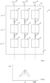
- an apparatus 10 comprising: a ground plane 12 and an array 20 of antennas 30.
- the array 20 comprises antennas 30 that can be arranged in parallel rows 24 and parallel columns 22.
- the array 20 is a regular array and comprises antennas 30 arranged in parallel rows 24 and parallel columns 22.
- coupling elements 40 For one or more columns 22 of the antennas 30 in the array 20, there is an aligned arrangement of coupling elements 40 comprising coupling elements 40 between the antennas 30 in the respective column 22.
- the coupling elements 40 are separate from the antennas 30 and are electrically floating.
- a ground plane is a technical term that refers to a conductive element at local ground potential. It provides a common ground potential at multiple different locations within the apparatus 10. However, it is not necessarily physically planar and can have any suitable physical topology. In some examples it can be physically planar. In some examples it can be physically planar and also flat.
- the columns 22 are aligned along virtual vertical lines and the rows 24 are aligned along virtual horizontal lines.
- the antennas 30 are separated vertically by coupling elements 40.
- the antennas 30 can be any suitable antennas. In the following examples patch antennas 30 are used.
- the array 20 has patch antennas 30 aligned in columns 22 and aligned in rows 24.
- Each of the M rows has N patch antennas 30 and each of the N columns has M patch antennas 30.
- the patch antennas 30 in at least some of the columns of the array 20 are separated by coupling elements 40.
- the coupling elements 40 in a particular column form an aligned arrangement.
- the coupling elements are aligned along virtual lines 26 that run parallel to the columns.
- patch antennas 30 of the array 20 are separated, vertically, by coupling elements 40.
- the coupling elements 40 are separate from the patch antennas 30 and are electrically floating.
- the conductive elements 40 are conductive and are not galvanically connected to an electric potential, for example the ground plane 12, or another conductive part of the apparatus 10. This allows the electrostatic potential of a coupling element 40 to 'float'.
- the arrangement of coupling elements 40 has a number of distinctive characteristics. For example, only one coupling element 40 is between neighboring patch antennas 30 in the column 22 direction. For example, for the rows 24 of patch antennas 30 in the array 20, there is no coupling element between the patch antennas 30 in the same row. For example, the columns 22 that have coupling elements 40 have the same coupling element 40 between patch antennas 30 in that column, that is, the coupling elements 40 in a column have the same characteristics such as shape, size and position relative to the patch antennas 30. Thus any respective column 22 of the aligned 26 arrangement of coupling elements 40 comprises coupling elements 40 of the same size and shape between the patch antennas 30 of the respective column.
- the arrangement of coupling elements 40 in the example illustrated, has reflection symmetry in a virtual mid-line (not illustrated) through boresight and parallel to the columns 22 of the array 20 and has reflection symmetry in a virtual mid- line (not illustrated) through boresight and parallel to the rows 24 of the array 20.
- the example arrangement of coupling elements 40 has 180 degree rotational symmetry about the boresight but does not have 90 degree rotational symmetry about the boresight.
- FIG 2 illustrates cross-polarization discrimination (XPD) for the array 20 of patch antennas 30, at boresight, without the coupling elements 40 (dotted line) and with the coupling elements 40 (solid line). It can be seen that the presence of the coupling elements 40 increase cross-polarization discrimination for the array 20 of patch antennas 30, at boresight.
- XPD cross-polarization discrimination
- the coupling elements 40 are, in at least some examples, elongate coupling elements 40 having a length L greater than a width W.
- the coupling element 40 has a strip shape.
- the width W is greater than a depth D.
- the length L of the elongate coupling elements 40 extends vertically
- the width W of the coupling elements 40 extends horizontally
- a depth (or height) of the coupling elements 40 extends outwardly.
- the coupling elements 40 are flat conductive elements (without slots or walls).
- the coupling elements 40 are galvanically isolated from each other and other conductors. The term 'galvanically isolated' means that there is no conductive direct current path.
- the aligned arrangement of coupling elements 40 in the respective columns 22 are aligned lengthwise along the virtual lines 26.
- a virtual line 26 travels lengthwise through the coupling elements 40 in a column 22 and bi-sects each of the coupling elements 40 widthwise.
- the coupling elements 40 have a fixed, constant width along their length. However, in some other examples, the coupling elements can have a variable width along their length. For example, the coupling elements 40 can be tapered.
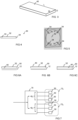
- some or all of the patch antennas 30 of the array 20 has a patch radiator 32 and feeds 34 for a first polarization and a second polarization orthogonal to the first polarization.
- FIG 4 illustrates in cross-sectional view an example of such a patch antenna 30.
- the radiator 32 of patch antenna 30 is separated from the feeds 34 by dielectric 33.
- the boresight direction is vertical within the plane of the paper.
- the patch radiators 32 also form an array corresponding to the array 20.
- some or all of the patch radiators 32 of the array have the same operational frequency range (or ranges). Consequently, in at least some examples, some or all of the patch radiators 32 of the array of patch radiators have the same size and shape which define electrical characteristics such as electrical length. In at least some examples, some or all of the patch radiators 32 of the array of patch radiators have the same feed arrangement of feeds 34.
- FIG 5 illustrates, in plan view, an example of a feed arrangement that provides feeds 34 for a first polarization and a second polarization orthogonal to the first polarization.
- the dual polarized feed arrangement is a balanced feed with opposing conductive feed elements 35 configured to provide a feed 34 for the first polarization and opposing conductive feed elements 37 configured to provide a feed 34 for the second polarization.
- the feed elements 35, 37 lie in a flat plane that is parallel to the plane of the patch radiator 32.
- the feed elements 35 are aligned in that flat plane in a direction offset by -90 degrees from a direction in that flat plane in which the feed elements 37 are aligned.
- the center of the feed arrangement, where virtual lines through the feed elements 35 and the feed elements 37 meet, is aligned with virtual line 26 (not illustrated in this FIG). This provides symmetrical coupling between the different polarizations.
- the feed element of the feed 34, on the combiner PCB is circular and the patch radiators are rectangular.
- FIGs 6A, 6B, 6C illustrate some bit not necessarily all of the arrangements possible for the ground plane 12, a patch radiator 32 of the patch antenna 40 and associated coupling elements 40.
- the ground plane 12 lies in a flat plane
- patch radiator 32 lies in a flat plane
- the coupling element 40 lies in a flat plane.
- the ground plane 12 is physically separated from the patch radiator 32.
- the ground plane 12 and the patch radiator 32 are not co-planar.
- the patch radiator 32 and its adjacent coupling element(s) 40 are not co-planar.
- the patch radiator 32 and its adjacent coupling element(s) 40 are co-planar.
- the patch radiator 32 and its adjacent coupling element(s) 40 are provided by a printed wiring board (PWB) 50.
- the patch radiator 32 occupies one side (or layer) of the PWB 50 and the coupling element(s) 40 occupy a different side (or layer) of the PWB 50.
- the patch radiator 32 and its adjacent coupling element(s) 40 are provided by a printed wiring board (PWB) 50.
- the patch radiator 32 occupies one side (or layer) of the PWB 50 and the coupling element(s) 40 occupy the same side (or layer) of the PWB 50.
- ground plane 12 occupies one side (or layer) of the PWB 50
- the patch radiator 32 occupies a different side (or layer) of the PWB 50
- the coupling element(s) 40 occupies a side (or layer) of the PWB 50.
- the side (or layer) of the PWB 50 occupied by the coupling element(s) 40 can be the same side (or layer) to that occupied by the patch radiator 32 or can be a different side (or layer) to that occupied by the patch radiator 32.
- the coupling elements 40 of the apparatus 10 can occupy a common side (or layer) of the PWB 50. In some examples, the coupling elements 40 of the apparatus 10 can occupy more than one side (or layer) of the PWB 50.
- the feeds 34 are not illustrated in FIGs 6A, 6B, 6C for clarity of illustration.
- the feeds will normally be provided in a single flat plane. They can be provided as part of a PWB 50 or separately to it.
- the feeds 34 are in some examples in a different plane to the patch radiators 32.
- the feeds 34 in at least some of these examples, or in other examples, are in a different plane to the coupling elements 40.
- Fig 7 illustrates an example of the apparatus 10 that comprises phase control circuitry 70.
- Phase control circuitry 70 is used to control application of a phase difference between two signals.
- the phase control circuitry 70 is configured to provide a relative phase adjustment to groups 72 of patch antennas 30 in the array 20 of patch antennas 30.
- the same relative phase adjustment ⁇ 1 is applied to patch antennas 30 within a group 72 1 and different relative phase adjustment(s) ⁇ 2 , ⁇ 3 ... ⁇ N is applied to patch antennas 30 in different groups 72 2, 72 3 ... 72 N to effect beam-steering.
- phase offset applied by phase control circuitry 70 varies across the columns.
- phase offset applied by phase control circuitry 70 varies across the rows.
- phase offset applied by phase control circuitry 70 varies across the columns and the across the rows.
- phase offset applied by phase control circuitry 70 varies with each horizontal group e.g. by each column.
- the arrangement of patch antennas 30 and coupling elements 40 is not symmetric in the horizontal and vertical.
- the size and shape of the patch radiators 32 are not symmetric, the spacing between patch radiators 32 is not symmetric, the distribution of coupling elements 40 is not symmetric and the shape of coupling elements 40 is not symmetric.
- an azimuth (horizontal) beam steering angle is much wider (for example +/-50deg) than elevation (for example +/-5deg).
- the spacing between patch radiators 32 can be close to half wavelength in the horizontal direction (between columns, within rows).
- the coupling elements 40 are the same in all columns, that is, the coupling elements 40 in different columns have the same characteristics such as shape, size and position relative the patch antennas 30.
- the coupling elements 40 do not vary their characteristics in the column direction
- the coupling elements 40 are not all the same or are not the same across all different columns.
- the coupling elements 40 if present in a particular column, are the same that is, the coupling elements 40 have the same characteristics such as shape, size and position relative the patch antennas 30.
- the coupling elements 40 in different columns are not necessarily the same and have different characteristics such as different shape, different size and/or different position relative the patch antennas 30.
- the coupling elements 40 vary their characteristics in the row 24 direction (less coupling as one moves to the outer peripheral columns).
- the coupling elements 40 are closer to adjacent patch antennas 30 in a column, in a column 22 direction, at the center of the regular array 20 of patch antennas 30, than in a column towards a periphery or edge of the regular array 20 of patch antennas 30.
- a length of a coupling elements 40 decreases with distance in a first direction from a center of the array 20 and a size of a gap (in a second direction orthogonal to the first direction) increases with distance in the first direction from the center of the array 20.
- the first direction is an azimuthal (horizontal) direction and the second direction is an elevation (vertical) direction.
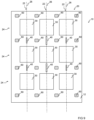
- the apparatus 10 additionally comprises grounded isolation towers 60 as illustrated in FIG 9 .
- the example of FIG 9 is based on the previous example of FIG 8 but grounded isolation towers 60 can be used with the example of FIG 1 or other examples.
- the grounded isolation towers 50 are conductive elements that extend outwardly from the plane of the page and have a depth (height) in that direction that is significant compared to in-plane dimensions such as, for example, the azimuthal (horizontal) dimension (width) or elevation (vertical) dimension (length).
- the grounded isolation towers 50 therefore have a relative height/depth, compared to width and length dimensions, that is much greater than that of a coupling element 40.
- the grounded isolation towers 50 are galvanically interconnected to the ground plane 12.
- the grounded isolation towers 50 can be formed as vias within the PWB 50, for example, extending from the ground pane 12.
- a grounded isolation tower 50 is positioned at corners of patch antennas 30. For example, where four corners of four different patch antennas 30 face each other there is a grounded isolation tower 50.
- the grounded isolation towers 50 form a regular array and are positioned where an (interstitial) space between columns 22 of patch antennas 30 and an (interstitial) space between rows 24 of patch antennas 30 meet.
- the array 20 of patch antennas 30 is an N row by M column array.
- that array of grounded isolation towers 50 comprises an (N-1) row by (M-1) column array that is 'within' the array 20.
- the grounded isolation towers 50 are positioned at corners of patch antennas 30 in the regular array of patch antennas.
- the array 20 of patch antennas 30 is an N row by M column array.
- that array of grounded isolation towers 50 is an (N+1) row by (M+1) column array.
- a grounded isolation tower 50 is positioned at each corner of each patch antenna 30.
- FIG 10 illustrates an example of a portion of an apparatus 10 as previously described. It has similarities to the apparatus 10 illustrated in FIG 9 . It comprises grounded isolation towers 60 and also comprises coupling elements 40 of variable area and/or length.
- FIG 11 illustrates an example of a whole apparatus 10 of which the portion illustrated in FIG 10 is a part.
- FIG 12 illustrates an example of a part of the feed arrangement for the apparatus 10 of FIG 11 .
- the feed arrangement comprises feeds 34 and is similar to that previously described with reference to FIG 5 .
- the array has a length (vertical) of 720 mm and a width (horizontal) of 420mm.
- the horizontal spacing between patch radiators 32 is 32mm.
- the vertical spacing between patch radiators is 42mm.
- the patch radiators are separated from the ground plane 12 by a distance of 4.2mm.
- FIG 13 illustrates circuitry for providing feeds 34 for a first polarization and a second polarization orthogonal to the first polarization.
- the dual polarized feed arrangement is a balanced feed with opposing conductive feed elements 35 configured to provide a feed 34 for the first polarization and opposing conductive feed elements 37 configured to provide a feed 34 for the second polarization.
- a feed S1 for a first signal connects via a 180 degree balun.
- a feed S2 for a second signal connects via a 180 degree balun.
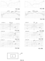
- FIGs 14B, 15B, 16B, 17B, 18B illustrate simulated characteristics of the apparatus 10 as previously described.
- FIGs 14A, 15A, 16A, 17A, 18A illustrate simulated characteristics of the apparatus 10, if adapted to remove the coupling elements 40.
- a comparison of the respective figures FIGs 14A, 15A, 16A, 17A, 18A against FIGs 14B, 15B, 16B, 17B, 18B illustrates effects of the coupling elements 40.
- FIGs 14A, 14B illustrate variation of reflection coefficients S11 and S12 (range -40dB to 0 in FIG 14A ; -35dB to 0 in FIG 14B ;) with frequency (range 4 to 5.4 GHz in both FIGs).
- FIGs 15A, 15B illustrate variation of XPD Cross Polar Discrimination ("Co-polar gain” - "X-polar gain”) with azimuthal angle for a beam steered at boresight.
- the different traces are for 4.4GHz, 4.7GHz and 5Ghz.
- FIGs 16A, 17A, 18A illustrate variation of Cross Polar Discrimination (XPD) and co-polar gain (CO) with azimuthal angle at 5GHz , for beam steering angles of 0° ( FIG 16A ), 50° ( FIG 17A ) and 30° ( FIG 18A ) where the apparatus 10 is without coupling elements 40 and FIGs 16B, 17B, 18B illustrate variation of Cross Polar Discrimination (XPD) and co-polar gain (CO) with azimuthal angle at 5GHz , for beam steering angles of 0° ( FIG 16B ), 50° ( FIG 17B ) and 30° ( FIG 18B ) where the apparatus 10 has coupling elements 40 .
- Cross Polar Discrimination XPD is the difference between the co-polar gain and cross-polar gain(log scale).
- XPD is greater over a 3dB beamwidth BW compared to FIG 16A .
- the presence of coupling elements 40 significantly improves XPD at boresight.
- XPD is not compromised by the presence of coupling elements 40.
- Cross-polar discrimination (XPD) over 4400-5000MHz is >20dB @ boresight and >10dB over whole steering range.
- Isolation towers 60 can be used to increase XPD at edges.
- Coupling elements 40 (and increased coupling) can be used to increase XPD at boresight.
- the XPD increases (X-pol component decreases) at azimuth angles close to boresight but gets worse at larger azimuth angles close to sector edges. Because the co and cross-polarization beam of the whole array 20 is the sum of the array 20 one can then use this effect to improve (or control) the overall XPD of the array 20 beam by using tight coupling at the middle columns 22 of the array 20 and loose coupling at the edges.
- the apparatus 10 uses floating coupling strips 40 added between patch radiators 32 to adjust the cross polar component level of each column 22 of the array. Columns 22 are used to form a sum beam of the whole array 20. To achieve good XPD over a wide horizontal sector, different coupling (from the coupling elements 40) is applied at each array 20 column 22 depending on the column 22 position in the array 20. Tight couplings (narrow gaps) are used at the middle columns 22 of the array 20 and loose couplings (wide gaps) or no coupling elements 40 are used at the array 20 edges. The coupling is between a specific coupling element 40 and a patch radiator 32 on either side of it in a particular column.
- the apparatus has particular application as a beam steering array 20 for higher frequency products (>2GHz) products.
- a product can be a base station system or a portable electronic device.
- the apparatus can have particular application as a beam steering array 20 for sub-6GHz products especially on the highest sub-6GHz frequency variants at 4400-5000MHz.
- Element cross-polar discrimination (XPD) over 4400-5000MHz band needs to be >20dB @ boresight and >10dB over whole steering range to minimize leakage between MIMO channels and also to minimize channel noise.
- the apparatus 10 provides a digital beam steering array 20 below 6GHz that supports multi-user-MIMO (multi-input multi-output) and provides sufficient horizontal and vertical beam steering range over a wide frequency bandwidth with stable peak gain.
- the manufacturing cost of the apparatus 10 is low and it is light weight (low mass).
- FIG 19 illustrates an example of product 100, for example a portable electronic device or a base station system (or part of a base station system)
- Thea base station system 100 (or part of a base station system) can be configured for beamforming, for example, multiple-input multiple-output (MIMO) operation and can comprise the apparatus 10 as previously described for beam-steering.
- MIMO multiple-input multiple-output
- An operational resonant mode is a frequency range over which an antenna can efficiently operate.
- An operational resonant mode may be defined as where the return loss S11 of the antenna is greater than an operational threshold T.
- a property of the instance can be a property of only that instance or a property of the class or a property of a sub-class of the class that includes some but not all of the instances in the class. It is therefore implicitly disclosed that a feature described with reference to one example but not with reference to another example, can where possible be used in that other example as part of a working combination but does not necessarily have to be used in that other example.
- 'a' or 'the' is used in this document with an inclusive not an exclusive meaning. That is any reference to X comprising a/the Y indicates that X may comprise only one Y or may comprise more than one Y unless the context clearly indicates the contrary. If it is intended to use 'a' or 'the' with an exclusive meaning then it will be made clear in the context. In some circumstances the use of 'at least one' or 'one or more' may be used to emphasis an inclusive meaning but the absence of these terms should not be taken to infer any exclusive meaning.
Landscapes
- Engineering & Computer Science (AREA)
- Computer Networks & Wireless Communication (AREA)
- Signal Processing (AREA)
- Variable-Direction Aerials And Aerial Arrays (AREA)
- Waveguide Aerials (AREA)
Claims (13)
- Einrichtung (10), die Folgendes umfasst:eine Grundplatte (12);ein Array (20) von Antennen (30), wobei das Array Antennen umfasst, die in parallelen Zeilen (24) und mindestens drei parallelen Spalten (22) angeordnet sind;für eine oder mehrere Spalten der Antennen im Array ist eine ausgerichtete Anordnung von Kopplungselementen (40) vorgesehen, die zwischen den Antennen in der jeweiligen Spalte Kopplungselemente umfassen,wobei die Kopplungselemente von den Antennen getrennt und elektrisch potenzialfrei sind;wobei die Kopplungselemente in einer Spalte zu einer Mitte des Arrays von Antennen in einer Spaltenrichtung benachbarten Antennen in einer Spalte des Arrays näher sind als in einer Spalte zu einem Umfang des Arrays von Antennen; undwobei jede der Antennen im Array von Antennen einen Radiator (32) und Speisepunkte (34) für eine erste Polarisierung und eine zweite Polarisierung orthogonal zur ersten Polarisierung umfasst.
- Einrichtung (10) nach Anspruch 1, wobei die Kopplungselemente (40) eine Kreuzpolarisierungsunterscheidung für das Array (20) von Antennen (30) in einer Sichtlinie erhöht, bei der es sich um eine Richtung orthogonal zu einer flachen Ebene des Arrays von Antennen handelt.
- Einrichtung (10) nach Anspruch 1 oder 2, wobei die Kopplungselemente (40) langgestreckt sind und eine Länge aufweisen, die größer ist als eine Breite, und wobei die ausgerichtete Anordnung von Kopplungselementen in den jeweiligen Spalten (22) längs ausgerichtet sind.
- Einrichtung (10) nach einem der vorhergehenden Ansprüche, wobei die ausgerichtete Anordnung von Kopplungselementen (40) in einer jeweiligen Spalte (22) entlang einer virtuellen Linie (26) angeordnet sind, die die Antennen (30) der jeweiligen Spalte schneidet.
- Einrichtung (10) nach einem der vorhergehenden Ansprüche, wobei die Kopplungselemente (40) flache leitfähige Elemente sind.
- Einrichtung (10) nach einem der vorhergehenden Ansprüche, die eine Leiterplatte (50) umfasst, wobei die Leiterplatte die Kopplungselemente (40) umfasst und die Antennen (30) umfasst.
- Einrichtung (10) nach einem der vorhergehenden Ansprüche, wobei eine jeweilige Spalte (22) der ausgerichteten Anordnung von Kopplungselementen (40) zwischen den Antennen (30) der jeweiligen Spalte Kopplungselemente derselben Größe und Form umfasst.
- Einrichtung (10) nach einem der vorhergehenden Ansprüche, wobei die Kopplungselemente (40) ihre Eigenschaften in einer Spaltenrichtung nicht variieren
- Einrichtung (10) nach einem der vorhergehenden Ansprüche, wobei die Kopplungselemente (40) ihre Eigenschaften in einer Zeilenrichtung variieren.
- Einrichtung (10) nach Anspruch 1, die Mittel zum Steuern von mindestens einer Phase (70) zwischen Speisepunkten (34) umfasst.
- Einrichtung (10) nach einem der vorhergehenden Ansprüche, die Mittel zum Bereitstellen einer relativen Phasenanpassung (70) für Gruppen von Antennen (30) im Array (20) von Antennen umfasst, wobei auf Antennen innerhalb einer Gruppe dieselbe relative Phasenanpassung angewandt wird und auf Antennen in verschiedenen Gruppen eine andere relative Phasenanpassung angewandt wird, um eine Strahllenkung zu bewirken.
- Einrichtung (10) nach einem der vorhergehenden Ansprüche, die geerdete Isoliertürme (60) umfasst, die an Ecken von Antennen (30) im Array von Antennen positioniert sind.
- Basisstationssystem oder tragbare elektronische Vorrichtung (100), das bzw. die für einen Multiple-Input-Multiple-Output-Betrieb ausgelegt ist und die Einrichtung (10) nach einem der vorhergehenden Ansprüche umfasst.
Applications Claiming Priority (1)
| Application Number | Priority Date | Filing Date | Title |
|---|---|---|---|
| FI20215128 | 2021-02-08 |
Publications (2)
| Publication Number | Publication Date |
|---|---|
| EP4040602A1 EP4040602A1 (de) | 2022-08-10 |
| EP4040602B1 true EP4040602B1 (de) | 2025-03-05 |
Family
ID=80218733
Family Applications (1)
| Application Number | Title | Priority Date | Filing Date |
|---|---|---|---|
| EP22155135.1A Active EP4040602B1 (de) | 2021-02-08 | 2022-02-04 | Anordnung von patch-antennen |
Country Status (3)
| Country | Link |
|---|---|
| US (1) | US12003038B2 (de) |
| EP (1) | EP4040602B1 (de) |
| CN (1) | CN114914714A (de) |
Families Citing this family (3)
| Publication number | Priority date | Publication date | Assignee | Title |
|---|---|---|---|---|
| KR102902612B1 (ko) * | 2020-01-16 | 2025-12-19 | 삼성전자주식회사 | 통신 시스템에서 플로팅 라디에이터를 포함하는 안테나 모듈 및 이를 포함하는 전자 장치 |
| WO2021160263A1 (en) * | 2020-02-13 | 2021-08-19 | Nokia Technologies Oy | Communication control mechanism for multi-panel ue |
| US12489199B2 (en) * | 2022-12-21 | 2025-12-02 | Outdoor Wireless Networks LLC | Base station antennas having partially reflective surface isolation walls |
Family Cites Families (21)
| Publication number | Priority date | Publication date | Assignee | Title |
|---|---|---|---|---|
| DE19627015C2 (de) * | 1996-07-04 | 2000-07-13 | Kathrein Werke Kg | Antennenfeld |
| GB0200585D0 (en) | 2002-01-11 | 2002-02-27 | Csa Ltd | Antenna with adjustable beam direction |
| US20140043195A1 (en) | 2010-08-26 | 2014-02-13 | Jaybeam Uk | Device and method for controlling azimuth beamwidth across a wide frequency range |
| ES2667008T3 (es) | 2011-03-25 | 2018-05-09 | Quintel Technology Limited | Método y aparato para supresión de polarización cruzada de radiación de antena |
| TWI509885B (zh) | 2013-07-24 | 2015-11-21 | Wistron Neweb Corp | 功率分配器及射頻裝置 |
| US9391375B1 (en) * | 2013-09-27 | 2016-07-12 | The United States Of America As Represented By The Secretary Of The Navy | Wideband planar reconfigurable polarization antenna array |
| CN103943970A (zh) | 2014-04-21 | 2014-07-23 | 广州博纬通信科技有限公司 | 一种双极化宽频阵列天线 |
| US9502780B2 (en) * | 2015-01-15 | 2016-11-22 | Northrop Grumman Systems Corporation | Antenna array using sandwiched radiating elements above a ground plane and fed by a stripline |
| JP6742397B2 (ja) | 2016-03-04 | 2020-08-19 | 株式会社村田製作所 | アレーアンテナ |
| EP3460907B1 (de) | 2016-06-14 | 2021-10-13 | Mitsubishi Electric Corporation | Gruppenantennenvorrichtung |
| CN209133693U (zh) | 2016-09-21 | 2019-07-19 | 广东通宇通讯股份有限公司 | 天线、mimo天线及用于降低天线互耦能量的隔离条 |
| CN113708059B (zh) * | 2017-05-16 | 2025-10-28 | 华为技术有限公司 | 一种天线 |
| JP6954376B2 (ja) | 2017-12-28 | 2021-10-27 | 株式会社村田製作所 | アンテナアレイおよびアンテナモジュール |
| CN108448239B (zh) * | 2018-02-28 | 2019-11-15 | 维沃移动通信有限公司 | 一种毫米波天线阵列及移动终端 |
| CN109216940B (zh) | 2018-08-17 | 2021-01-12 | 西安电子科技大学 | 超宽带紧耦合阵列天线 |
| CN109149108A (zh) | 2018-09-05 | 2019-01-04 | 武汉虹信通信技术有限责任公司 | 一种去耦装置及mimo天线 |
| FI128682B (en) | 2018-12-31 | 2020-10-15 | Stealthcase Oy | A diversity dispersal device and a method for using it |
| KR102613218B1 (ko) * | 2019-03-15 | 2023-12-13 | 삼성전자 주식회사 | 안테나 및 그것을 포함하는 전자 장치 |
| US12034218B2 (en) | 2019-03-26 | 2024-07-09 | Telefonaktiebolaget Lm Ericsson (Publ) | Frasera Antenna Radiator (FAR) for 5G array antennas |
| CN110504535B (zh) * | 2019-08-07 | 2020-11-06 | 上海交通大学 | 双极化圆柱共形微带磁振子八木端射阵列天线 |
| US11069960B2 (en) * | 2019-10-09 | 2021-07-20 | Commscope Technologies Llc | Multiband base station antennas having improved gain and/or interband isolation |
-
2022
- 2022-02-04 EP EP22155135.1A patent/EP4040602B1/de active Active
- 2022-02-04 US US17/665,094 patent/US12003038B2/en active Active
- 2022-02-08 CN CN202210117619.5A patent/CN114914714A/zh active Pending
Also Published As
| Publication number | Publication date |
|---|---|
| US20220255222A1 (en) | 2022-08-11 |
| CN114914714A (zh) | 2022-08-16 |
| EP4040602A1 (de) | 2022-08-10 |
| US12003038B2 (en) | 2024-06-04 |
Similar Documents
| Publication | Publication Date | Title |
|---|---|---|
| EP3975337B1 (de) | Antenneneinheit und endgerätevorrichtung | |
| EP4040602B1 (de) | Anordnung von patch-antennen | |
| US6593891B2 (en) | Antenna apparatus having cross-shaped slot | |
| US8466846B1 (en) | Ultra wide band balanced antipodal tapered slot antenna and array with edge treatment | |
| US5892482A (en) | Antenna mutual coupling neutralizer | |
| US10424847B2 (en) | Wideband dual-polarized current loop antenna element | |
| CN112290227B (zh) | 一种双频双圆极化天线阵列 | |
| US11476591B2 (en) | Multi-port multi-beam antenna system on printed circuit board with low correlation for MIMO applications and method therefor | |
| US12294141B2 (en) | Antenna calibration boards having non-uniform coupler sections | |
| CA2540375A1 (en) | Antenna arrays using long slot apertures and balanced feeds | |
| WO2021104191A1 (zh) | 天线单元及电子设备 | |
| CN106785360A (zh) | 一种宽角扫描的双极化宽带振子天线及天线阵列 | |
| CN112952375A (zh) | 形成波束的方法和装置 | |
| WO2021231249A1 (en) | Duplexed base station antennas | |
| CN210040568U (zh) | 单层同轴馈电双极化微带阵列天线 | |
| US20210119345A1 (en) | Antenna unit, antenna module, and electronic device | |
| US12199703B2 (en) | Sector-splitting multi-beam base station antennas having multiple beamforming networks per polarization | |
| WO2023091876A1 (en) | Base station antennas including feed circuitry and calibration circuitry that share a board | |
| TWI674704B (zh) | 低旁波瓣陣列天線 | |
| JPH06125214A (ja) | 平面アンテナ | |
| CN119965552B (zh) | 一种宽带双圆极化天线单元及阵列 | |
| WO2007106976A1 (en) | Tri-polar antenna array element | |
| KR200320101Y1 (ko) | 삼중 편파 안테나 | |
| CN215418585U (zh) | 微带阵列天线 | |
| KR20050069286A (ko) | 다층구조의 광대역 원형편파 안테나 |
Legal Events
| Date | Code | Title | Description |
|---|---|---|---|
| PUAI | Public reference made under article 153(3) epc to a published international application that has entered the european phase |
Free format text: ORIGINAL CODE: 0009012 |
|
| STAA | Information on the status of an ep patent application or granted ep patent |
Free format text: STATUS: THE APPLICATION HAS BEEN PUBLISHED |
|
| AK | Designated contracting states |
Kind code of ref document: A1 Designated state(s): AL AT BE BG CH CY CZ DE DK EE ES FI FR GB GR HR HU IE IS IT LI LT LU LV MC MK MT NL NO PL PT RO RS SE SI SK SM TR |
|
| STAA | Information on the status of an ep patent application or granted ep patent |
Free format text: STATUS: REQUEST FOR EXAMINATION WAS MADE |
|
| 17P | Request for examination filed |
Effective date: 20230210 |
|
| RBV | Designated contracting states (corrected) |
Designated state(s): AL AT BE BG CH CY CZ DE DK EE ES FI FR GB GR HR HU IE IS IT LI LT LU LV MC MK MT NL NO PL PT RO RS SE SI SK SM TR |
|
| GRAP | Despatch of communication of intention to grant a patent |
Free format text: ORIGINAL CODE: EPIDOSNIGR1 |
|
| STAA | Information on the status of an ep patent application or granted ep patent |
Free format text: STATUS: GRANT OF PATENT IS INTENDED |
|
| INTG | Intention to grant announced |
Effective date: 20241114 |
|
| GRAS | Grant fee paid |
Free format text: ORIGINAL CODE: EPIDOSNIGR3 |
|
| GRAA | (expected) grant |
Free format text: ORIGINAL CODE: 0009210 |
|
| STAA | Information on the status of an ep patent application or granted ep patent |
Free format text: STATUS: THE PATENT HAS BEEN GRANTED |
|
| AK | Designated contracting states |
Kind code of ref document: B1 Designated state(s): AL AT BE BG CH CY CZ DE DK EE ES FI FR GB GR HR HU IE IS IT LI LT LU LV MC MK MT NL NO PL PT RO RS SE SI SK SM TR |
|
| REG | Reference to a national code |
Ref country code: GB Ref legal event code: FG4D |
|
| REG | Reference to a national code |
Ref country code: CH Ref legal event code: EP |
|
| REG | Reference to a national code |
Ref country code: IE Ref legal event code: FG4D |
|
| REG | Reference to a national code |
Ref country code: DE Ref legal event code: R096 Ref document number: 602022011284 Country of ref document: DE |
|
| PG25 | Lapsed in a contracting state [announced via postgrant information from national office to epo] |
Ref country code: RS Free format text: LAPSE BECAUSE OF FAILURE TO SUBMIT A TRANSLATION OF THE DESCRIPTION OR TO PAY THE FEE WITHIN THE PRESCRIBED TIME-LIMIT Effective date: 20250605 |
|
| PG25 | Lapsed in a contracting state [announced via postgrant information from national office to epo] |
Ref country code: FI Free format text: LAPSE BECAUSE OF FAILURE TO SUBMIT A TRANSLATION OF THE DESCRIPTION OR TO PAY THE FEE WITHIN THE PRESCRIBED TIME-LIMIT Effective date: 20250305 |
|
| REG | Reference to a national code |
Ref country code: NL Ref legal event code: MP Effective date: 20250305 |
|
| PG25 | Lapsed in a contracting state [announced via postgrant information from national office to epo] |
Ref country code: ES Free format text: LAPSE BECAUSE OF FAILURE TO SUBMIT A TRANSLATION OF THE DESCRIPTION OR TO PAY THE FEE WITHIN THE PRESCRIBED TIME-LIMIT Effective date: 20250305 |
|
| REG | Reference to a national code |
Ref country code: LT Ref legal event code: MG9D |
|
| PG25 | Lapsed in a contracting state [announced via postgrant information from national office to epo] |
Ref country code: NO Free format text: LAPSE BECAUSE OF FAILURE TO SUBMIT A TRANSLATION OF THE DESCRIPTION OR TO PAY THE FEE WITHIN THE PRESCRIBED TIME-LIMIT Effective date: 20250605 |
|
| PG25 | Lapsed in a contracting state [announced via postgrant information from national office to epo] |
Ref country code: HR Free format text: LAPSE BECAUSE OF FAILURE TO SUBMIT A TRANSLATION OF THE DESCRIPTION OR TO PAY THE FEE WITHIN THE PRESCRIBED TIME-LIMIT Effective date: 20250305 |
|
| PG25 | Lapsed in a contracting state [announced via postgrant information from national office to epo] |
Ref country code: LV Free format text: LAPSE BECAUSE OF FAILURE TO SUBMIT A TRANSLATION OF THE DESCRIPTION OR TO PAY THE FEE WITHIN THE PRESCRIBED TIME-LIMIT Effective date: 20250305 |
|
| PG25 | Lapsed in a contracting state [announced via postgrant information from national office to epo] |
Ref country code: BG Free format text: LAPSE BECAUSE OF FAILURE TO SUBMIT A TRANSLATION OF THE DESCRIPTION OR TO PAY THE FEE WITHIN THE PRESCRIBED TIME-LIMIT Effective date: 20250305 Ref country code: GR Free format text: LAPSE BECAUSE OF FAILURE TO SUBMIT A TRANSLATION OF THE DESCRIPTION OR TO PAY THE FEE WITHIN THE PRESCRIBED TIME-LIMIT Effective date: 20250606 |
|
| REG | Reference to a national code |
Ref country code: AT Ref legal event code: MK05 Ref document number: 1773837 Country of ref document: AT Kind code of ref document: T Effective date: 20250305 |
|
| PG25 | Lapsed in a contracting state [announced via postgrant information from national office to epo] |
Ref country code: NL Free format text: LAPSE BECAUSE OF FAILURE TO SUBMIT A TRANSLATION OF THE DESCRIPTION OR TO PAY THE FEE WITHIN THE PRESCRIBED TIME-LIMIT Effective date: 20250305 |
|
| PG25 | Lapsed in a contracting state [announced via postgrant information from national office to epo] |
Ref country code: SE Free format text: LAPSE BECAUSE OF FAILURE TO SUBMIT A TRANSLATION OF THE DESCRIPTION OR TO PAY THE FEE WITHIN THE PRESCRIBED TIME-LIMIT Effective date: 20250305 |
|
| PG25 | Lapsed in a contracting state [announced via postgrant information from national office to epo] |
Ref country code: SM Free format text: LAPSE BECAUSE OF FAILURE TO SUBMIT A TRANSLATION OF THE DESCRIPTION OR TO PAY THE FEE WITHIN THE PRESCRIBED TIME-LIMIT Effective date: 20250305 |
|
| PG25 | Lapsed in a contracting state [announced via postgrant information from national office to epo] |
Ref country code: PT Free format text: LAPSE BECAUSE OF FAILURE TO SUBMIT A TRANSLATION OF THE DESCRIPTION OR TO PAY THE FEE WITHIN THE PRESCRIBED TIME-LIMIT Effective date: 20250707 |
|
| PG25 | Lapsed in a contracting state [announced via postgrant information from national office to epo] |
Ref country code: PL Free format text: LAPSE BECAUSE OF FAILURE TO SUBMIT A TRANSLATION OF THE DESCRIPTION OR TO PAY THE FEE WITHIN THE PRESCRIBED TIME-LIMIT Effective date: 20250305 Ref country code: IT Free format text: LAPSE BECAUSE OF FAILURE TO SUBMIT A TRANSLATION OF THE DESCRIPTION OR TO PAY THE FEE WITHIN THE PRESCRIBED TIME-LIMIT Effective date: 20250305 |
|
| PG25 | Lapsed in a contracting state [announced via postgrant information from national office to epo] |
Ref country code: AT Free format text: LAPSE BECAUSE OF FAILURE TO SUBMIT A TRANSLATION OF THE DESCRIPTION OR TO PAY THE FEE WITHIN THE PRESCRIBED TIME-LIMIT Effective date: 20250305 |
|
| PG25 | Lapsed in a contracting state [announced via postgrant information from national office to epo] |
Ref country code: EE Free format text: LAPSE BECAUSE OF FAILURE TO SUBMIT A TRANSLATION OF THE DESCRIPTION OR TO PAY THE FEE WITHIN THE PRESCRIBED TIME-LIMIT Effective date: 20250305 Ref country code: CZ Free format text: LAPSE BECAUSE OF FAILURE TO SUBMIT A TRANSLATION OF THE DESCRIPTION OR TO PAY THE FEE WITHIN THE PRESCRIBED TIME-LIMIT Effective date: 20250305 |
|
| PG25 | Lapsed in a contracting state [announced via postgrant information from national office to epo] |
Ref country code: RO Free format text: LAPSE BECAUSE OF FAILURE TO SUBMIT A TRANSLATION OF THE DESCRIPTION OR TO PAY THE FEE WITHIN THE PRESCRIBED TIME-LIMIT Effective date: 20250305 |
|
| PG25 | Lapsed in a contracting state [announced via postgrant information from national office to epo] |
Ref country code: SK Free format text: LAPSE BECAUSE OF FAILURE TO SUBMIT A TRANSLATION OF THE DESCRIPTION OR TO PAY THE FEE WITHIN THE PRESCRIBED TIME-LIMIT Effective date: 20250305 |
|
| PG25 | Lapsed in a contracting state [announced via postgrant information from national office to epo] |
Ref country code: IS Free format text: LAPSE BECAUSE OF FAILURE TO SUBMIT A TRANSLATION OF THE DESCRIPTION OR TO PAY THE FEE WITHIN THE PRESCRIBED TIME-LIMIT Effective date: 20250705 |
|
| REG | Reference to a national code |
Ref country code: DE Ref legal event code: R097 Ref document number: 602022011284 Country of ref document: DE |
|
| PLBE | No opposition filed within time limit |
Free format text: ORIGINAL CODE: 0009261 |
|
| STAA | Information on the status of an ep patent application or granted ep patent |
Free format text: STATUS: NO OPPOSITION FILED WITHIN TIME LIMIT |
|
| PG25 | Lapsed in a contracting state [announced via postgrant information from national office to epo] |
Ref country code: DK Free format text: LAPSE BECAUSE OF FAILURE TO SUBMIT A TRANSLATION OF THE DESCRIPTION OR TO PAY THE FEE WITHIN THE PRESCRIBED TIME-LIMIT Effective date: 20250305 |
|
| REG | Reference to a national code |
Ref country code: CH Ref legal event code: L10 Free format text: ST27 STATUS EVENT CODE: U-0-0-L10-L00 (AS PROVIDED BY THE NATIONAL OFFICE) Effective date: 20260114 |
|
| 26N | No opposition filed |
Effective date: 20251208 |
|
| PGFP | Annual fee paid to national office [announced via postgrant information from national office to epo] |
Ref country code: GB Payment date: 20260106 Year of fee payment: 5 |
|
| PGFP | Annual fee paid to national office [announced via postgrant information from national office to epo] |
Ref country code: DE Payment date: 20251230 Year of fee payment: 5 |