EP4040582A1 - Battery module and battery pack including same - Google Patents
Battery module and battery pack including same Download PDFInfo
- Publication number
- EP4040582A1 EP4040582A1 EP21872686.7A EP21872686A EP4040582A1 EP 4040582 A1 EP4040582 A1 EP 4040582A1 EP 21872686 A EP21872686 A EP 21872686A EP 4040582 A1 EP4040582 A1 EP 4040582A1
- Authority
- EP
- European Patent Office
- Prior art keywords
- layer
- battery
- battery cell
- module
- battery module
- Prior art date
- Legal status (The legal status is an assumption and is not a legal conclusion. Google has not performed a legal analysis and makes no representation as to the accuracy of the status listed.)
- Pending
Links
- 239000006260 foam Substances 0.000 claims abstract description 25
- 230000008961 swelling Effects 0.000 claims abstract description 15
- 239000011347 resin Substances 0.000 claims description 22
- 229920005989 resin Polymers 0.000 claims description 22
- 229920000139 polyethylene terephthalate Polymers 0.000 claims description 12
- 239000005020 polyethylene terephthalate Substances 0.000 claims description 12
- 229910052751 metal Inorganic materials 0.000 claims description 11
- 239000002184 metal Substances 0.000 claims description 11
- 239000000463 material Substances 0.000 claims description 10
- -1 polyethylene terephthalate Polymers 0.000 claims description 10
- 239000004743 Polypropylene Substances 0.000 claims description 7
- 238000004806 packaging method and process Methods 0.000 claims description 7
- 229920001155 polypropylene Polymers 0.000 claims description 7
- 239000004677 Nylon Substances 0.000 claims description 5
- 229920001778 nylon Polymers 0.000 claims description 5
- 229910052782 aluminium Inorganic materials 0.000 claims description 3
- XAGFODPZIPBFFR-UHFFFAOYSA-N aluminium Chemical compound [Al] XAGFODPZIPBFFR-UHFFFAOYSA-N 0.000 claims description 3
- 229920002635 polyurethane Polymers 0.000 claims description 3
- 239000004814 polyurethane Substances 0.000 claims description 3
- 230000006835 compression Effects 0.000 description 14
- 238000007906 compression Methods 0.000 description 14
- 238000007789 sealing Methods 0.000 description 8
- 230000000694 effects Effects 0.000 description 3
- 238000010521 absorption reaction Methods 0.000 description 2
- 238000010586 diagram Methods 0.000 description 2
- 230000035515 penetration Effects 0.000 description 2
- 239000000047 product Substances 0.000 description 2
- 239000006227 byproduct Substances 0.000 description 1
- 238000010292 electrical insulation Methods 0.000 description 1
- 238000004146 energy storage Methods 0.000 description 1
- 239000002803 fossil fuel Substances 0.000 description 1
- 230000004927 fusion Effects 0.000 description 1
- 230000005484 gravity Effects 0.000 description 1
- 238000009413 insulation Methods 0.000 description 1
- 238000000034 method Methods 0.000 description 1
- 238000012986 modification Methods 0.000 description 1
- 230000004048 modification Effects 0.000 description 1
- 230000001151 other effect Effects 0.000 description 1
- 230000003389 potentiating effect Effects 0.000 description 1
Images


Classifications
-
- H—ELECTRICITY
- H01—ELECTRIC ELEMENTS
- H01M—PROCESSES OR MEANS, e.g. BATTERIES, FOR THE DIRECT CONVERSION OF CHEMICAL ENERGY INTO ELECTRICAL ENERGY
- H01M50/00—Constructional details or processes of manufacture of the non-active parts of electrochemical cells other than fuel cells, e.g. hybrid cells
- H01M50/20—Mountings; Secondary casings or frames; Racks, modules or packs; Suspension devices; Shock absorbers; Transport or carrying devices; Holders
- H01M50/204—Racks, modules or packs for multiple batteries or multiple cells
- H01M50/207—Racks, modules or packs for multiple batteries or multiple cells characterised by their shape
- H01M50/211—Racks, modules or packs for multiple batteries or multiple cells characterised by their shape adapted for pouch cells
-
- H—ELECTRICITY
- H01—ELECTRIC ELEMENTS
- H01M—PROCESSES OR MEANS, e.g. BATTERIES, FOR THE DIRECT CONVERSION OF CHEMICAL ENERGY INTO ELECTRICAL ENERGY
- H01M50/00—Constructional details or processes of manufacture of the non-active parts of electrochemical cells other than fuel cells, e.g. hybrid cells
- H01M50/20—Mountings; Secondary casings or frames; Racks, modules or packs; Suspension devices; Shock absorbers; Transport or carrying devices; Holders
- H01M50/233—Mountings; Secondary casings or frames; Racks, modules or packs; Suspension devices; Shock absorbers; Transport or carrying devices; Holders characterised by physical properties of casings or racks, e.g. dimensions
- H01M50/242—Mountings; Secondary casings or frames; Racks, modules or packs; Suspension devices; Shock absorbers; Transport or carrying devices; Holders characterised by physical properties of casings or racks, e.g. dimensions adapted for protecting batteries against vibrations, collision impact or swelling
-
- H—ELECTRICITY
- H01—ELECTRIC ELEMENTS
- H01M—PROCESSES OR MEANS, e.g. BATTERIES, FOR THE DIRECT CONVERSION OF CHEMICAL ENERGY INTO ELECTRICAL ENERGY
- H01M10/00—Secondary cells; Manufacture thereof
- H01M10/42—Methods or arrangements for servicing or maintenance of secondary cells or secondary half-cells
- H01M10/48—Accumulators combined with arrangements for measuring, testing or indicating the condition of cells, e.g. the level or density of the electrolyte
-
- H—ELECTRICITY
- H01—ELECTRIC ELEMENTS
- H01M—PROCESSES OR MEANS, e.g. BATTERIES, FOR THE DIRECT CONVERSION OF CHEMICAL ENERGY INTO ELECTRICAL ENERGY
- H01M50/00—Constructional details or processes of manufacture of the non-active parts of electrochemical cells other than fuel cells, e.g. hybrid cells
- H01M50/10—Primary casings, jackets or wrappings of a single cell or a single battery
- H01M50/102—Primary casings, jackets or wrappings of a single cell or a single battery characterised by their shape or physical structure
- H01M50/105—Pouches or flexible bags
-
- H—ELECTRICITY
- H01—ELECTRIC ELEMENTS
- H01M—PROCESSES OR MEANS, e.g. BATTERIES, FOR THE DIRECT CONVERSION OF CHEMICAL ENERGY INTO ELECTRICAL ENERGY
- H01M50/00—Constructional details or processes of manufacture of the non-active parts of electrochemical cells other than fuel cells, e.g. hybrid cells
- H01M50/10—Primary casings, jackets or wrappings of a single cell or a single battery
- H01M50/116—Primary casings, jackets or wrappings of a single cell or a single battery characterised by the material
- H01M50/122—Composite material consisting of a mixture of organic and inorganic materials
-
- H—ELECTRICITY
- H01—ELECTRIC ELEMENTS
- H01M—PROCESSES OR MEANS, e.g. BATTERIES, FOR THE DIRECT CONVERSION OF CHEMICAL ENERGY INTO ELECTRICAL ENERGY
- H01M50/00—Constructional details or processes of manufacture of the non-active parts of electrochemical cells other than fuel cells, e.g. hybrid cells
- H01M50/10—Primary casings, jackets or wrappings of a single cell or a single battery
- H01M50/116—Primary casings, jackets or wrappings of a single cell or a single battery characterised by the material
- H01M50/124—Primary casings, jackets or wrappings of a single cell or a single battery characterised by the material having a layered structure
-
- H—ELECTRICITY
- H01—ELECTRIC ELEMENTS
- H01M—PROCESSES OR MEANS, e.g. BATTERIES, FOR THE DIRECT CONVERSION OF CHEMICAL ENERGY INTO ELECTRICAL ENERGY
- H01M50/00—Constructional details or processes of manufacture of the non-active parts of electrochemical cells other than fuel cells, e.g. hybrid cells
- H01M50/20—Mountings; Secondary casings or frames; Racks, modules or packs; Suspension devices; Shock absorbers; Transport or carrying devices; Holders
- H01M50/218—Mountings; Secondary casings or frames; Racks, modules or packs; Suspension devices; Shock absorbers; Transport or carrying devices; Holders characterised by the material
- H01M50/22—Mountings; Secondary casings or frames; Racks, modules or packs; Suspension devices; Shock absorbers; Transport or carrying devices; Holders characterised by the material of the casings or racks
- H01M50/229—Composite material consisting of a mixture of organic and inorganic materials
-
- H—ELECTRICITY
- H01—ELECTRIC ELEMENTS
- H01M—PROCESSES OR MEANS, e.g. BATTERIES, FOR THE DIRECT CONVERSION OF CHEMICAL ENERGY INTO ELECTRICAL ENERGY
- H01M50/00—Constructional details or processes of manufacture of the non-active parts of electrochemical cells other than fuel cells, e.g. hybrid cells
- H01M50/20—Mountings; Secondary casings or frames; Racks, modules or packs; Suspension devices; Shock absorbers; Transport or carrying devices; Holders
- H01M50/218—Mountings; Secondary casings or frames; Racks, modules or packs; Suspension devices; Shock absorbers; Transport or carrying devices; Holders characterised by the material
- H01M50/22—Mountings; Secondary casings or frames; Racks, modules or packs; Suspension devices; Shock absorbers; Transport or carrying devices; Holders characterised by the material of the casings or racks
- H01M50/231—Mountings; Secondary casings or frames; Racks, modules or packs; Suspension devices; Shock absorbers; Transport or carrying devices; Holders characterised by the material of the casings or racks having a layered structure
-
- H—ELECTRICITY
- H01—ELECTRIC ELEMENTS
- H01M—PROCESSES OR MEANS, e.g. BATTERIES, FOR THE DIRECT CONVERSION OF CHEMICAL ENERGY INTO ELECTRICAL ENERGY
- H01M50/00—Constructional details or processes of manufacture of the non-active parts of electrochemical cells other than fuel cells, e.g. hybrid cells
- H01M50/20—Mountings; Secondary casings or frames; Racks, modules or packs; Suspension devices; Shock absorbers; Transport or carrying devices; Holders
- H01M50/233—Mountings; Secondary casings or frames; Racks, modules or packs; Suspension devices; Shock absorbers; Transport or carrying devices; Holders characterised by physical properties of casings or racks, e.g. dimensions
- H01M50/24—Mountings; Secondary casings or frames; Racks, modules or packs; Suspension devices; Shock absorbers; Transport or carrying devices; Holders characterised by physical properties of casings or racks, e.g. dimensions adapted for protecting batteries from their environment, e.g. from corrosion
-
- H—ELECTRICITY
- H01—ELECTRIC ELEMENTS
- H01M—PROCESSES OR MEANS, e.g. BATTERIES, FOR THE DIRECT CONVERSION OF CHEMICAL ENERGY INTO ELECTRICAL ENERGY
- H01M2220/00—Batteries for particular applications
- H01M2220/20—Batteries in motive systems, e.g. vehicle, ship, plane
-
- Y—GENERAL TAGGING OF NEW TECHNOLOGICAL DEVELOPMENTS; GENERAL TAGGING OF CROSS-SECTIONAL TECHNOLOGIES SPANNING OVER SEVERAL SECTIONS OF THE IPC; TECHNICAL SUBJECTS COVERED BY FORMER USPC CROSS-REFERENCE ART COLLECTIONS [XRACs] AND DIGESTS
- Y02—TECHNOLOGIES OR APPLICATIONS FOR MITIGATION OR ADAPTATION AGAINST CLIMATE CHANGE
- Y02E—REDUCTION OF GREENHOUSE GAS [GHG] EMISSIONS, RELATED TO ENERGY GENERATION, TRANSMISSION OR DISTRIBUTION
- Y02E60/00—Enabling technologies; Technologies with a potential or indirect contribution to GHG emissions mitigation
- Y02E60/10—Energy storage using batteries
Definitions
- the present disclosure relates to a battery module and a battery pack comprising the same, and more particularly to a battery module that controls cell swelling, and a battery pack comprising the same.
- a secondary battery has attracted much attention as an energy source in various products such as a mobile device and an electric vehicle.
- the secondary battery is a potent energy resource that can replace the use of existing products using fossil fuels, and is in the spotlight as an environment-friendly energy source because it does not generate by-products due to energy use.
- a method of configuring a battery module composed of at least one battery cell and then adding other components to at least one battery module to configure a battery pack is common.
- Such a battery module includes a battery cell stack in which a plurality of battery cells are stacked, a module frame for housing the battery cell stack, and a compression pad formed between the module frame and the outermost battery cells of the battery cell stack or between a plurality of battery cells.
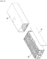
- Fig. 1 is a diagram showing a battery module in which a compression pad is formed according to the related art.
- Fig. 2 is a cross-sectional view taken along the stacking direction of the battery cell stack of Fig. 1 .
- a compression pad 30 is formed between the outermost battery cell of the battery cell stack 10 and the module frame 20. Although not shown, the compression pad 30 may be further formed in a part between the battery cells 11 of the battery cell stack 10.
- a battery module comprising: a battery cell stack in which a plurality of battery cells are stacked, and a module frame for housing the battery cell stack, wherein the battery cell comprises a pouch case and an electrode assembly housed in the pouch case, and wherein a foam pad layer for controlling cell swelling is located at the outermost part of the pouch case.
- the pouch case may be configured such that an inner resin layer and a metal layer are sequentially formed between the electrode assembly and the outermost layer formed of the foam pad layer in a direction toward the outermost layer from the electrode assembly.
- the battery module may further include an outer resin layer located between the metal layer and the outermost layer.
- the battery module may further include a packaging sheet layer located between the outer resin layer and the outermost layer.
- the packaging sheet layer may be formed of a nylon or polyethylene terephthalate (PET) material.
- the inner resin layer, the metal layer, and the outer resin layer may be a polypropylene (PP) layer, an aluminum layer, and a nylon layer, respectively.
- PP polypropylene
- the foam pad layer may be formed of a polyethylene terephthalate (PET) material or a polyurethane material.
- PET polyethylene terephthalate
- a battery cell located at the outermost part of the battery cell stack may be in contact with a side surface part of the module frame, and the battery cell part in contact with the side surface part of the module frame may be the outermost layer formed of the foam pad layer.
- a foam pad layer may be formed at the outermost part of each pouch case of the battery cells included in the battery cell stack.
- a battery pack comprising the above-mentioned battery module.
- the foam pad layer is formed at the outermost part of the pouch case, and thus, the pouch battery cell can control by itself a swelling.
- the pressure distribution and deformation amount can be uniform when viewed as a whole of the battery cell stack.
- planar when referred to as “planar”, it means when a target portion is viewed from the upper side, and when referred to as “cross-sectional”, it means when a target portion is viewed from the side of a cross section cut vertically.
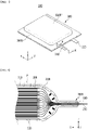
- Fig. 3 is an exploded perspective view showing a pouch-type battery cell according to an embodiment of the present disclosure.
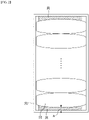
- Fig. 4 is a perspective view showing a state in which the pouch-type battery cell of FIG. 3 is assembled.
- Fig. 5 is a cross-sectional view taken along the cutting line A-A' of Fig 4 .
- Fig. 6 is an enlarged cross-sectional view of the region P of Fig. 5 .
- the pouch-type battery cell 100 may be manufactured by housing an electrode assembly 200 inside the pouch case 300 and then sealing it.
- the electrode assembly 200 may include a positive electrode, a negative electrode, and a separator disposed between the positive electrode and the negative electrode.
- the electrode assembly 200 may be a stack type electrode assembly, a jelly-roll type electrode assembly, or a stack/folding-type electrode assembly.
- the pouch case 300 is composed of a laminate sheet, and may include a resin layer for heat fusion and a metal layer for preventing material penetration.
- the upper case 310 may include an inner resin layer 310a for sealing, a metal layer 310b for preventing material penetration, an outer resin layer 310c, and a foam pad layer 310d for controlling cell swelling.
- the foam pad layer 310d according to the present embodiment is located on the outermost layer of the pouch case 300.
- the foam pad layer 310d may be formed of a polyethylene terephthalate (PET) material or a polyurethane material.
- PET polyethylene terephthalate
- the foam pad layer 310d may be a pad made of a foam having a certain degree of compression ratio in order to control swelling.
- the foam pad layer 310d may have flexible features such that it can absorb swelling without being too stiff.
- a packaging sheet layer (not shown) may be further included between the foam pad layer 310d and the outer resin layer 310c.
- the layer structure concerning the upper case 310 described above may be equally applied to a lower case 320.
- the lower case 320 may include an inner resin layer, a metal layer, an outer resin layer, and a foam pad layer for controlling cell swelling along a direction away from the electrode assembly 200.
- the outer resin layer 310c and a packaging sheet layer may have excellent tensile strength and weather resistance compared to their thickness and have electrical insulation property in order to protect the pouch-type secondary battery 100 from the outside.
- Each of the outer resin layer 310c and the packaging sheet layer may include a polyethylene terephthalate (PET) resin or a nylon resin.
- PET polyethylene terephthalate
- the metal layer 310b may prevent air, moisture and the like from flowing into the pouch-type battery layer 100.
- the metal layer 310b may include aluminum (Al).
- the inner resin layer 310a may be heat-fused to each other by heat and pressure applied in a state where the electrode assembly 200 is built-in.
- the inner resin layer 310a may include unstretched polypropylene (CPP) or polypropylene (PP).
- a recessed housing part 300ST in which the electrode assembly 200 can be seated may be formed in each of the upper case 310 and the lower case 320.
- Sealing parts 300S1 and 300S2 may be provided along the outer periphery of the housing part 300ST for each of the upper case 310 and the lower case 320.
- the sealing part 300S1 of the upper case 310 and the sealing part 300S2 of the lower case 320 can be heat-fused to each other to form the sealing part 300S and seal the pouch case 300.
- one side of the upper case and one side of the lower case can be integrally connected to each other, and the remaining three sides can be heat-fused.
- each of the plurality of positive electrodes and the plurality of negative electrodes included in the electrode assembly 200 may include a positive electrode tab and a negative electrode tab, to which electrode leads 210 and 220 are connected.
- one of the electrode leads 210 and 220 may be a positive electrode lead, and the other may be a negative electrode lead.
- the electrode leads 210 and 220 connected to the electrode assembly 200 protrude from one end part of the pouch case 300 and are exposed to the outside of the pouch case 300.
- the battery module includes a battery cell stack 110 formed by stacking a plurality of battery cells 100 in one direction, and a module frame 500 for housing the battery cell stack 110.
- a stacking direction of the battery cells 100 may be perpendicular to a protruding direction of the electrode leads 210 and 220.
- the battery cell 100 located at the outermost part of the battery cell stack 110 can be in contact with the side surface part of the module frame 500.
- a foam pad layer 310d may be formed at the outermost part of the pouch case 300 of each of the battery cells 100 included in the battery cell stack 110.
- a foam pad layer may be formed on the outermost layer of each of the upper case 310 and the lower case 320.
- the compression pad was applied to each of several battery cells, the pressure distribution and deformation amount were different for each battery cell.
- the battery cell stack 110 may be uniform in pressure distribution and deformation amount when viewed as a whole.
- one or more of the battery modules according to the present embodiments can be packaged in a pack case to form a battery pack.
- the above-mentioned battery module and battery pack including the same can be applied to various devices.
- a device can be applied to a vehicle means such as an electric bicycle, an electric vehicle, or a hybrid vehicle, but the present disclosure is not limited thereto, and is applicable to various devices capable of using a battery module, which also falls under the scope of the present disclosure.
Landscapes
- Chemical & Material Sciences (AREA)
- Chemical Kinetics & Catalysis (AREA)
- Electrochemistry (AREA)
- General Chemical & Material Sciences (AREA)
- Engineering & Computer Science (AREA)
- Composite Materials (AREA)
- Inorganic Chemistry (AREA)
- Materials Engineering (AREA)
- Manufacturing & Machinery (AREA)
- Battery Mounting, Suspending (AREA)
- Sealing Battery Cases Or Jackets (AREA)
Applications Claiming Priority (2)
| Application Number | Priority Date | Filing Date | Title |
|---|---|---|---|
| KR1020200126067A KR20220042803A (ko) | 2020-09-28 | 2020-09-28 | 전지 모듈 및 이를 포함하는 전지팩 |
| PCT/KR2021/009487 WO2022065653A1 (ko) | 2020-09-28 | 2021-07-22 | 전지 모듈 및 이를 포함하는 전지팩 |
Publications (1)
| Publication Number | Publication Date |
|---|---|
| EP4040582A1 true EP4040582A1 (en) | 2022-08-10 |
Family
ID=80844610
Family Applications (1)
| Application Number | Title | Priority Date | Filing Date |
|---|---|---|---|
| EP21872686.7A Pending EP4040582A1 (en) | 2020-09-28 | 2021-07-22 | Battery module and battery pack including same |
Country Status (6)
| Country | Link |
|---|---|
| US (1) | US20220393285A1 (ko) |
| EP (1) | EP4040582A1 (ko) |
| JP (1) | JP7408218B2 (ko) |
| KR (1) | KR20220042803A (ko) |
| CN (1) | CN217114565U (ko) |
| WO (1) | WO2022065653A1 (ko) |
Families Citing this family (1)
| Publication number | Priority date | Publication date | Assignee | Title |
|---|---|---|---|---|
| KR20220100430A (ko) * | 2021-01-08 | 2022-07-15 | 주식회사 엘지에너지솔루션 | 발포층을 포함하는 파우치형 전지셀 및 상기 파우치형 전지셀을 포함하는 전지모듈 |
Family Cites Families (12)
| Publication number | Priority date | Publication date | Assignee | Title |
|---|---|---|---|---|
| JP6462003B2 (ja) | 2014-10-07 | 2019-01-30 | エルジー・ケム・リミテッド | 安全性及び作動寿命が向上したバッテリーモジュール |
| KR101655564B1 (ko) * | 2014-11-06 | 2016-09-07 | 주식회사 엘지화학 | 이차전지용 파우치 외장재 및 이를 포함하는 파우치형 이차전지 |
| CN204558556U (zh) * | 2015-02-10 | 2015-08-12 | 江阴骏驰光电科技有限公司 | 一种含双发泡膜的锂电池铝塑包装膜 |
| US10084217B2 (en) | 2016-02-16 | 2018-09-25 | Lg Chem, Ltd. | Battery system |
| JP2018116805A (ja) | 2017-01-17 | 2018-07-26 | 積水化学工業株式会社 | 二次電池モジュール |
| KR102085998B1 (ko) * | 2017-03-14 | 2020-03-06 | 주식회사 엘지화학 | 보호 필름이 부착된 파우치형 전지셀 |
| CN109585703A (zh) * | 2017-09-28 | 2019-04-05 | 苏州柯莱美高分子材料科技有限公司 | 一种锂电池用镁锂合金塑料复合膜及其制备方法 |
| KR102597128B1 (ko) * | 2018-08-08 | 2023-11-03 | 에스케이온 주식회사 | 파우치형 이차전지 모듈 |
| KR102600089B1 (ko) | 2018-10-12 | 2023-11-07 | 주식회사 엘지에너지솔루션 | 배터리 모듈 |
| JP6990642B2 (ja) | 2018-10-18 | 2022-01-12 | 本田技研工業株式会社 | 蓄電モジュール及び蓄電モジュールの製造方法 |
| CN111106270A (zh) | 2018-10-26 | 2020-05-05 | 宁德新能源科技有限公司 | 多层片材和电池 |
| JP2020139062A (ja) | 2019-02-28 | 2020-09-03 | 積水化学工業株式会社 | バッテリー用クッション材 |
-
2020
- 2020-09-28 KR KR1020200126067A patent/KR20220042803A/ko unknown
-
2021
- 2021-07-22 CN CN202190000187.9U patent/CN217114565U/zh active Active
- 2021-07-22 JP JP2022521393A patent/JP7408218B2/ja active Active
- 2021-07-22 WO PCT/KR2021/009487 patent/WO2022065653A1/ko unknown
- 2021-07-22 EP EP21872686.7A patent/EP4040582A1/en active Pending
- 2021-07-22 US US17/774,588 patent/US20220393285A1/en active Pending
Also Published As
| Publication number | Publication date |
|---|---|
| US20220393285A1 (en) | 2022-12-08 |
| CN217114565U (zh) | 2022-08-02 |
| WO2022065653A1 (ko) | 2022-03-31 |
| JP7408218B2 (ja) | 2024-01-05 |
| KR20220042803A (ko) | 2022-04-05 |
| JP2022553155A (ja) | 2022-12-22 |
Similar Documents
| Publication | Publication Date | Title |
|---|---|---|
| CN106067525B (zh) | 二次电池和具有该二次电池的电池模块 | |
| KR102267606B1 (ko) | 셀 조립체에 대한 초기 가압력 강화 구조를 갖는 배터리 모듈 및 그 제조방법 | |
| US10790479B2 (en) | Secondary battery and fabricating method thereof | |
| EP4040582A1 (en) | Battery module and battery pack including same | |
| KR20170009495A (ko) | 전지케이스에 충격 흡수층을 포함하고 있는 파우치형 이차전지 | |
| EP3467903B1 (en) | Battery pack | |
| KR20170058047A (ko) | 일회용 가스 포집부를 포함하고 있는 파우치형 전지케이스 및 이를 포함하는 이차전지의 제조방법 | |
| US11114712B2 (en) | Battery module having improved cooling structure | |
| KR101472613B1 (ko) | 중대형 전지팩 및 그 패키징 방법 | |
| KR102216744B1 (ko) | 배터리셀, 및 이를 포함하는 배터리 모듈 | |
| EP4064427A1 (en) | Pouch type secondary battery and battery module including same | |
| JP7403748B2 (ja) | 発泡層を含むパウチ形電池セル及び該パウチ形電池セルを含む電池モジュール | |
| KR101456735B1 (ko) | 중대형 전지팩 및 그 패키징 방법 | |
| KR20220107611A (ko) | 이차전지용 벤팅 장치 및 이를 포함하는 파우치형 이차전지 | |
| KR101516449B1 (ko) | 중대형 전지팩 및 그 패키징 방법 | |
| KR20210003607A (ko) | 밀착형 쿨링플레이트를 포함하는 배터리 팩 및 이를 포함하는 디바이스 | |
| KR20160055600A (ko) | 이차전지용 파우치 및 이를 포함하는 파우치형 이차전지 | |
| CN114761208B (zh) | 袋型电池制造设备 | |
| EP4057432A1 (en) | Cell tray and storage container comprising same | |
| CN218513653U (zh) | 电池单元和包括电池单元的电池模块 | |
| US20230335842A1 (en) | Battery module and battery pack including the same | |
| KR101464796B1 (ko) | 중대형 전지팩 및 그 패키징 방법 | |
| KR20220081268A (ko) | 이차전지 및 이를 포함하는 전지 모듈 | |
| KR20220023497A (ko) | 스웰링시 분출되는 플레어와 스파크를 포집할 수 있는 포켓이 구비된 전지 모듈 | |
| KR20230033902A (ko) | 전지셀 및 이를 포함하는 전지 모듈 |
Legal Events
| Date | Code | Title | Description |
|---|---|---|---|
| STAA | Information on the status of an ep patent application or granted ep patent |
Free format text: STATUS: THE INTERNATIONAL PUBLICATION HAS BEEN MADE |
|
| PUAI | Public reference made under article 153(3) epc to a published international application that has entered the european phase |
Free format text: ORIGINAL CODE: 0009012 |
|
| STAA | Information on the status of an ep patent application or granted ep patent |
Free format text: STATUS: REQUEST FOR EXAMINATION WAS MADE |
|
| 17P | Request for examination filed |
Effective date: 20220505 |
|
| AK | Designated contracting states |
Kind code of ref document: A1 Designated state(s): AL AT BE BG CH CY CZ DE DK EE ES FI FR GB GR HR HU IE IS IT LI LT LU LV MC MK MT NL NO PL PT RO RS SE SI SK SM TR |
|
| DAV | Request for validation of the european patent (deleted) | ||
| DAX | Request for extension of the european patent (deleted) |