EP4040104B1 - Erzeugung von angaben über relative positionsverhältnisse für drei oder mehr sensoren - Google Patents
Erzeugung von angaben über relative positionsverhältnisse für drei oder mehr sensoren Download PDFInfo
- Publication number
- EP4040104B1 EP4040104B1 EP19947861.1A EP19947861A EP4040104B1 EP 4040104 B1 EP4040104 B1 EP 4040104B1 EP 19947861 A EP19947861 A EP 19947861A EP 4040104 B1 EP4040104 B1 EP 4040104B1
- Authority
- EP
- European Patent Office
- Prior art keywords
- sensors
- target
- sensor
- targets
- time points
- Prior art date
- Legal status (The legal status is an assumption and is not a legal conclusion. Google has not performed a legal analysis and makes no representation as to the accuracy of the status listed.)
- Active
Links
Images


Classifications
-
- G—PHYSICS
- G01—MEASURING; TESTING
- G01S—RADIO DIRECTION-FINDING; RADIO NAVIGATION; DETERMINING DISTANCE OR VELOCITY BY USE OF RADIO WAVES; LOCATING OR PRESENCE-DETECTING BY USE OF THE REFLECTION OR RERADIATION OF RADIO WAVES; ANALOGOUS ARRANGEMENTS USING OTHER WAVES
- G01S7/00—Details of systems according to groups G01S13/00, G01S15/00, G01S17/00
- G01S7/48—Details of systems according to groups G01S13/00, G01S15/00, G01S17/00 of systems according to group G01S17/00
- G01S7/4808—Evaluating distance, position or velocity data
-
- G—PHYSICS
- G01—MEASURING; TESTING
- G01S—RADIO DIRECTION-FINDING; RADIO NAVIGATION; DETERMINING DISTANCE OR VELOCITY BY USE OF RADIO WAVES; LOCATING OR PRESENCE-DETECTING BY USE OF THE REFLECTION OR RERADIATION OF RADIO WAVES; ANALOGOUS ARRANGEMENTS USING OTHER WAVES
- G01S17/00—Systems using the reflection or reradiation of electromagnetic waves other than radio waves, e.g. lidar systems
- G01S17/87—Combinations of systems using electromagnetic waves other than radio waves
-
- G—PHYSICS
- G01—MEASURING; TESTING
- G01S—RADIO DIRECTION-FINDING; RADIO NAVIGATION; DETERMINING DISTANCE OR VELOCITY BY USE OF RADIO WAVES; LOCATING OR PRESENCE-DETECTING BY USE OF THE REFLECTION OR RERADIATION OF RADIO WAVES; ANALOGOUS ARRANGEMENTS USING OTHER WAVES
- G01S17/00—Systems using the reflection or reradiation of electromagnetic waves other than radio waves, e.g. lidar systems
- G01S17/88—Lidar systems specially adapted for specific applications
- G01S17/89—Lidar systems specially adapted for specific applications for mapping or imaging
-
- G—PHYSICS
- G06—COMPUTING OR CALCULATING; COUNTING
- G06T—IMAGE DATA PROCESSING OR GENERATION, IN GENERAL
- G06T7/00—Image analysis
- G06T7/70—Determining position or orientation of objects or cameras
- G06T7/73—Determining position or orientation of objects or cameras using feature-based methods
-
- G—PHYSICS
- G06—COMPUTING OR CALCULATING; COUNTING
- G06T—IMAGE DATA PROCESSING OR GENERATION, IN GENERAL
- G06T7/00—Image analysis
- G06T7/80—Analysis of captured images to determine intrinsic or extrinsic camera parameters, i.e. camera calibration
-
- G—PHYSICS
- G06—COMPUTING OR CALCULATING; COUNTING
- G06T—IMAGE DATA PROCESSING OR GENERATION, IN GENERAL
- G06T2207/00—Indexing scheme for image analysis or image enhancement
- G06T2207/10—Image acquisition modality
- G06T2207/10028—Range image; Depth image; 3D point clouds
-
- G—PHYSICS
- G06—COMPUTING OR CALCULATING; COUNTING
- G06T—IMAGE DATA PROCESSING OR GENERATION, IN GENERAL
- G06T2207/00—Indexing scheme for image analysis or image enhancement
- G06T2207/20—Special algorithmic details
- G06T2207/20072—Graph-based image processing
-
- G—PHYSICS
- G06—COMPUTING OR CALCULATING; COUNTING
- G06T—IMAGE DATA PROCESSING OR GENERATION, IN GENERAL
- G06T2207/00—Indexing scheme for image analysis or image enhancement
- G06T2207/30—Subject of image; Context of image processing
- G06T2207/30221—Sports video; Sports image
-
- G—PHYSICS
- G06—COMPUTING OR CALCULATING; COUNTING
- G06T—IMAGE DATA PROCESSING OR GENERATION, IN GENERAL
- G06T2207/00—Indexing scheme for image analysis or image enhancement
- G06T2207/30—Subject of image; Context of image processing
- G06T2207/30244—Camera pose
Definitions
- the embodiment discussed herein is related to a generation method or the like.
- the distance measuring device such as a laser sensor
- the distance measuring device such as a laser sensor
- the distance measuring device is referred to as a "sensor”.
- an object is sensed from each directions using a plurality of sensors arranged around the object, and three-dimensional point clouds that are measurement results of the respective sensors are integrated, so that the object can be three-dimensionally reproduced.
- FIG. 25 is a diagram illustrating a result of integrating three-dimensional point clouds measured by a plurality of sensors.
- sensors 10A, 10B, 10C, and 10D are arranged around (front and back of) an object 1, and the sensors 10A to 10D measure the object 1 to obtain three-dimensional point clouds.
- a three-dimensional point cloud 11A is data based on the measurement result of the sensor 10A.
- a three-dimensional point cloud 11B is data based on the measurement result of the sensor 10B.
- a three-dimensional point cloud 11C is data based on the measurement result of the sensor 10C.
- a three-dimensional point cloud 11D is data based on the measurement result of the sensor 10D.
- an external parameter is used.
- the external parameter is information indicating a positional relationship among a plurality of sensors.
- an existing technique for calculating an external parameter for example, there are existing techniques 1 and 2.
- the existing technique 1 is an external calibration technique for calculating an external parameter of a sensor using a spherical target.
- one spherical target is observed by a first sensor and a second sensor a plurality of times while moving the spherical target.
- FIG. 26 is a diagram for describing the existing technique 1.
- Spherical targets 23a, 24a, and 25a are detected from the measurement results 13a, 14a, and 15a, respectively.
- the spherical targets 23a, 24a, and 25a are associated with the spherical targets 23b, 24b, and 25b, and an initial value of the external parameter is estimated on the basis of a positional relationship among the three-dimensional point clouds of the associated spherical targets.
- alignment of singular value decomposition is performed.
- the external parameter between the first sensor and the second sensor is optimized using bundle estimation or maximum likelihood estimation, and the external parameter is calculated.
- Image 16 illustrates an external calibration result.
- the positions of the spherical targets 23a, 24a, and 25a and the spherical targets 23b, 24b, and 25b match.
- the spherical target being able to be detected by the first sensor and the second sensor at the same time at least three time points while changing the position of the spherical target is the condition for calculating the external parameter.
- the existing technique 2 is a technique for detecting a target by image processing, and sequentially estimating an external parameter of each camera, using two cameras as starting points and using a direct linear transform (DLT) algorithm.
- DLT direct linear transform
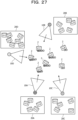
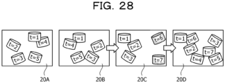
- FIGs. 27 and 28 are diagrams for describing the existing technique 2.
- FIG. 27 will be described.
- the target 2 is observed by the sensors 10A to 10D.
- the target 2 is observed by the sensors 10A to 10D.
- the target 2 is observed by the sensors 10A to 10D.
- the target 2 is observed by the sensors 10A, 10B, and 10D.
- the target 2 is observed by the sensors 10A, 10B, and 10D.
- the target 2 is observed by the sensors 10C and 10D.
- the target 2 is observed by the sensors 10C and 10D.
- the order of estimating the external parameters is predetermined.
- the sensors are selected in the order of the sensors 10B, 10C, and 10D with reference to the sensor 10A, and the external parameters are estimated.
- the target 2 available for estimation is the target 2 at time point already observed by the reference sensor or a selected sensor.
- Examples of the related art include as follows: Japanese Laid-open Patent Publication No. 2019-086476 ; and M. Ruan, "Extrinsic Calibration of 3D Sensors Using a Spherical Target," 3DV 2014 .
- M. Ruan "Extrinsic Calibration of 3D Sensors Using a Spherical Target," 3DV 2014 .
- the above-described existing technique 1 is based on the assumption that the external parameters of two sensors are grasped and further the first sensor and the second sensor are required to observe one spherical target at the same time. Therefore, in a case where sensing ranges of the first sensor and the second sensor are not shared, the spherical target is not able to be observed by the two sensors at the same time. Furthermore, even in a case where the shared sensing range is narrow, it is difficult for the two sensors to observe the spherical target a sufficient number of times because it is assumed to capture the spherical target a plurality of times while moving the spherical target. In such a case, conditions for estimating the external parameters of the first sensor and the second sensor are insufficient.
- the existing technique 1 is based on the assumption that all the sensors observe the target at the same time at each time point. Therefore, in a case where a pair not sharing the sensing range is present among the three or more sensors, the external parameters are not able to be estimated.
- the order of estimating the external parameters is predetermined. For example, as described in FIG. 28 , when the sensors are selected in the order of the sensors 10B, 10C, and 10D with reference to the sensor 10A and the external parameters are estimated, the targets that can be used to estimate the external parameter decreases in the observation result 20C and the distribution becomes biased. If the targets that can be used to estimate the external parameter are unevenly distributed, the estimation accuracy of the external parameter will become low. The decrease in the estimation accuracy also affects the estimation accuracy in the case of selecting the observation result 20D in the subsequent stage and estimating the external parameter.
- an object of the present invention is to provide a generation method, a generation program, and an information processing apparatus capable of accurately generating information indicating relative positional relationships such as an arrangement positional relationship and an angle of view relationship for three or more sensors.
- information indicating relative positional relationships such as an arrangement positional relationship and an angle of view relationship can be accurately generated.
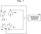
- FIG. 1 is a diagram illustrating an example of an information processing system according to a present embodiment 1.
- the information processing system according to the present embodiment 1 includes sensors 10A, 10B, 10C, and 10D and an information processing apparatus 100.
- Each of the sensors 10A to 10D is connected to the information processing apparatus 100 by wired or wireless means.
- FIG. 1 illustrates the sensors 10A to 10D, the information processing system may also include other sensors.
- the sensor 10A is a measuring device (laser sensor) that measures a distance between a point cloud constituting an object (or a target 2) and the sensor 10A.
- the sensor 10A outputs distance image data as a measurement result to the information processing apparatus 100.
- the distance image data includes information in which each pixel and a distance value are associated with each other.
- the distance image data is converted into three-dimensional point cloud data by the information processing apparatus 100.
- the three-dimensional point cloud data is information in which a point and coordinates of a three-dimensional orthogonal coordinate system are associated with each other for the point cloud.
- the sensor 10B is similar to the description of the sensor 10A.
- the sensors 10A and 10B are collectively referred to as "sensor(s) 10" as appropriate.
- the three-dimensional point cloud data is data obtained by converting distance image data measured by the sensor 10, but is appropriately expressed as the three-dimensional point cloud data measured by the sensor 10, and description about converting the distance image data into the three-dimensional point cloud data is omitted.
- the information processing system is a system that measures the object (not illustrated) using the sensor 10 and evaluates performance performed by the object. As preprocessing, the information processing system executes external calibration using the target 2 and generates external parameters. The information processing system integrates three-dimensional point cloud data measured by the sensors 10 on the basis of the generated external parameters, generates three-dimensional point cloud data of the entire object, and evaluates the performance performed by the object.
- the information processing apparatus 100 executes processing of generating a sensor connectivity graph, processing of reflecting a variance of targets in the sensor connectivity graph, and processing of specifying the order of selecting sensors.
- the target 2 is observed by the sensor 10A.
- the target 2 is observed by the sensor 10A.
- the target 2 is observed by the sensors 10A and 10B.
- the target 2 is observed by the sensors 10A and 10B.
- the target 2 is observed by the sensors 10A and 10B.
- the target 2 is observed by the sensors 10A, 10B, and 10C.
- the target 2 is observed by the sensors 10B and 10C.
- the target 2 is observed by the sensors 10B and 10D.
- the target 2 is observed by the sensors 10B, 10C, and 10D.
- the target 2 is observed by the sensors 10C and 10D.
- the target 2 is observed by the sensors 10C and 10D.
- the target 2 is observed by the sensors 10B, 10C, and 10D.
- the target 2 is observed by the sensor 10C.
- the information processing apparatus 100 specifies the number of times of a time point (hereinafter the share number) when the target 2 is detected at the same time point among the plurality of time points by a set of two sensors among the sensors 10A to 10D.
- the share number for the set of sensors 10A and 10D is "0".
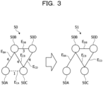
- the information processing apparatus 100 generates a target share number graph 50 on the basis of the share number specified for each set of two sensor.
- the target share number graph 50 includes nodes 50A, 50B, 50C, and 50D.
- the node 50A is a node corresponding to the sensor 10A.
- the node 50B is a node corresponding to the sensor 10B.
- the node 50C is a node corresponding to the sensor 10C.
- the node 50D is a node corresponding to the sensor 10D.
- the nodes 50A to 50D are connected by edges E, and each edge E is set with a weight according to the share number. Since the share number for the set of sensors 10A and 10B is "4", the information processing apparatus 100 sets the weight "4" in an edge E BA connecting the node 50A and the node 50B. Since the share number for the set of sensors 10A and 10C is "1", the information processing apparatus 100 sets the weight "1" in an edge E CA connecting the node 50A and the node 50D. Note that since the share number for the set of sensors 10A and 10D is "0", the node 50A and the node 50D are not connected by an edge.
- the information processing apparatus 100 sets the weight "4" in an edge E BC connecting the node 50B and the node 50C. Since the share number for the set of sensors 10B and 10D is "3", the information processing apparatus 100 sets the weight "3" in an edge E DB connecting the node 50B and the node 50D.
- the information processing apparatus 100 generates a sensor connectivity graph 51 by leaving the edges having the weight of "3" or more among the edges E.
- the information processing apparatus 100 generates the sensor connectivity graph 51 by deleting the edge E CA from the target share number graph 50 and leaving the edges E BA , E CB , E DB , and E CD .
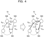
- FIG. 4 is a diagram for describing processing of reflecting a variance of a target in the sensor connectivity graph.
- the information processing apparatus 100 calculates a variance ⁇ 2 of the positions of the target group observed by the set of two sensors at each time points.
- the information processing apparatus 100 sets ""-2log ⁇ " as the weight of each edge E, and reflects the variance of the targets in the sensor connectivity graph. The smaller the edge weight, the larger the spatial variance of the positions of the target group observed by the set of two sensors (evenly distributed).
- the information processing apparatus 100 executes processing of specifying the order of selecting the sensors to be calculated for external parameters on the basis of a result of reflecting the variance of the targets 2 in the sensor connectivity graph 51.
- the information processing apparatus 100 determines a path that minimizes the sum of the edges E by a shortest path search. For example, the information processing apparatus 100 determines the path that minimizes the sum of the edges E, using the Bellman-Ford method or the like.
- the path that minimizes the sum of the edges E is the order of the sensors so that the spatial variance of the positions of the target groups becomes as large as possible.
- a reference node is the node 50A corresponding to the sensor 10A
- the path that minimizes the sum of the edges E is in the order of the node 50A, node 50B, node 50D, and node 50C.
- the order of the sensors in which the spatial variance of the positions of the target group becomes as large as possible is the sensor 10A, sensor 10B, sensor 10D, and sensor 10C.
- the information processing apparatus 100 selects the sensor 10B, the sensor 10D, and the sensor C in this order with reference to the sensor 10A, and estimates the external parameters.
- the information processing apparatus 100 selects the sensor 10B, the sensor 10D, and the sensor C in this order with reference to the sensor 10A, and estimates the external parameters.
- synthesizing the relative positions and orientations of the set of two sensors to be connected it is possible to calculate the external parameters of the sensor that is not directly connected to the reference sensor.
- FIG. 5 is a diagram for describing calculation of the external parameter of the sensor that is not directly connected.
- the node 50A, node 50B, node 50D, and node 50C correspond to the sensor 10A, sensor 10B, sensor 10C, and sensor 10D, respectively.
- the node 50A and the node 50C are not directly connected, but by executing the following processing, the relative positions and orientations of the reference sensor 10A and the sensor 10C can be calculated.
- the information processing apparatus 100 calculates the relative positions and orientations of the reference sensor 10A and the sensor 10C on the basis of the equation (1).
- each T is a matrix containing a rotation matrix and a translation vector.
- T CA T CD T DB T BA
- the information processing apparatus 100 executes observations by the sensors 10A to 10D while moving the target 2 at each time point, and specifies the share number indicating the number of times of a time point when the target 2 is detected at the same time point.
- the information processing apparatus 100 generates the target share number graph 50 in which the share number is the weight of the edge, and generates the sensor connectivity graph 51 obtained by leaving the edges E having the weight that is a predetermined number or more from the target share number graph 50.
- the set of nodes connected in the sensor connectivity graph 51 indicates a set of sensors in which the number of times the target 2 is observed at the same time point is a predetermined number or more.
- the information processing apparatus 100 calculates the variance ⁇ 2 of the positions of the target group observed by the set of two sensors at time points, sets "-2log ⁇ " as the weight of each edge E, and reflects the variance of the targets as a sensor in the sensor connectivity graph.
- the smaller the edge weight the larger the spatial variance of the positions of the target group observed by the set of two sensors.
- the information processing apparatus 100 specifies the path that minimizes the sum of the edges E, and specifies the order of the sensors 10 to be selected when calculating the external parameters on the basis of the specified path.
- the order of the sensors in which the spatial variance of the positions of the target group becomes as large as possible can be specified so that the calculation of the external parameters of the sensors 10 becomes stable. Therefore, for three or more sensors, information indicating relative positional relationships such as an arrangement positional relationship and an angle of view relationship may be accurately generated.
- FIG. 6 is a diagram for describing effects of the information processing apparatus according to the present embodiment 1.
- the upper part of FIG. 6 illustrates the order of selecting the sensors 10 in the case of using the existing technique 2.
- the lower row illustrates the order of selecting the sensors 10 specified by the information processing apparatus 100.
- the observation results of the sensors 10A to 10D are assumed to be observation results 20A to 20D.
- the sensors 10 are selected in a predetermined order, such as the sensors 10A, 10B, 10C, and 10D.
- the targets that can be used to estimate the external parameter decrease in the observation result 20C, and the distribution becomes biased. If the targets that can be used to estimate the external parameter are unevenly distributed, the estimation accuracy of the external parameter will become low.
- the sensors 10 are selected in the order of the sensors 10A, 10B, 10C, and 10D by using the sensor connectivity graph.
- the decrease in the estimation accuracy in the case of selecting the observation result 20C in the subsequent stage and estimating the external parameter can also be suppressed.
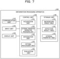
- FIG. 7 is a functional block diagram illustrating a configuration of the information processing apparatus according to the present embodiment 1.
- the information processing apparatus 100 includes a communication unit 110, an input unit 120, a display unit 130, a storage unit 140, and a control unit 150.
- the communication unit 110 is a processing unit that receives distance image data from the sensor 10 illustrated in FIG. 1 .
- the communication unit 110 outputs the received distance image data to the control unit 150.
- the communication unit 110 is an example of a communication device.
- the input unit 120 is an input device that inputs various types of information to the information processing apparatus 100.
- the input unit 120 corresponds to a keyboard, a mouse, a touch panel, and the like.
- the user operates the input unit 120 to input information indicating that installation of the target 2 has been completed to the information processing apparatus 100 each time the installation of the target 2 has been completed at each time point.
- the display unit 130 is a display device that displays information output from the control unit 150. For example, the display unit 130 displays skill certification, scoring results, and the like of various competitions.
- the display unit 130 corresponds to a liquid crystal display, an organic electroluminescence (EL) display, a touch panel, or the like.
- the storage unit 140 has a background image table 141, a detection result table 142, and an external parameter table 143.
- the storage unit 140 corresponds to a semiconductor memory element such as a random access memory (RAM) or a flash memory, or a storage device such as a hard disk drive (HDD).
- RAM random access memory
- HDD hard disk drive
- the background image table 141 is a table that stores background image data (distance image data) measured by each of the sensors 10A to 10D in the state of absence of the target 2.
- the detection result table 142 is a table that stores the point cloud and the position of the target 2 detected at each time point on the basis of the observation result of the sensor 10.
- FIG. 8 is a table illustrating an example of a data structure of the detection result table. As illustrated in FIG. 8 , the detection result table 142 stores sensor identification information and point cloud information of the target 2 at each time point.
- the sensor identification information is information that identifies the sensor 10. For example, pieces of the sensor identification information SE10A, SE10B, SE10C, and SE10D correspond to the sensor 10A, the sensor 10B, the sensor 10C, and the sensor 10D, respectively.
- the point cloud information of the target is data indicating a relationship between a three-dimensional point cloud of the target 2 and three-dimensional coordinates of points included in the point cloud. Note that, in a case where the target is not detected at time point of the corresponding sensor identification information, "no target" is stored.
- the external parameter table 143 is a table that stores the external parameters generated by an external parameter generation processing unit 152, which will be described below.
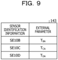
- FIG. 9 is a table illustrating an example of a data structure of an external parameter table. As illustrated in FIG. 9 , the external parameter table 143 associates sensor identification information with an external parameter.
- the sensor identification information is information that identifies the sensor 10.
- the external parameter is data indicating position and orientation relative to the reference sensor 10. In the present embodiment 1, the reference sensor is the sensor 10A.
- the external parameter T BA is data indicating the relative position and orientation of the sensor 10B with reference to the sensor 10A.
- An external parameter T CA is data indicating the relative position and orientation of the sensor 10C with reference to the sensor 10A.
- An external parameter T DA is data indicating the relative position and orientation of the sensor 10D with reference to the sensor 10A.
- the control unit 150 includes an acquisition unit 151, the external parameter generation processing unit 152, an integration unit 153, a fitting processing unit 154, and an evaluation unit 155.
- the control unit 150 is implemented by a central processing unit (CPU) or a micro processing unit (MPU), or hard-wired logic such as an application specific integrated circuit (ASIC) or a field programmable gate array (FPGA), or the like.
- CPU central processing unit
- MPU micro processing unit
- ASIC application specific integrated circuit
- FPGA field programmable gate array
- the acquisition unit 151 is a processing unit that acquires the distance image data from the sensor 10 via the communication unit 110. For example, timing at which the acquisition unit 151 acquires the distance image data is instructed by the user who operates the input unit 120.
- the acquisition unit 151 takes a difference between the distance image data and the background image data stored in the background image table 141, and generates background difference image data.
- the acquisition unit 151 outputs the background difference image data to the external parameter generation processing unit 152.
- the acquisition unit 151 generates the background difference data corresponding to the sensor 10A by the difference between the distance image data measured by the sensor 10A and the background image data corresponding to the sensor 10A.
- the acquisition unit 151 generates the background difference data corresponding to the sensor 10B by the difference between the distance image data measured by the sensor 10B and the background image data corresponding to the sensor 10B.
- the acquisition unit 151 generates the background difference data corresponding to the sensor 10C by the difference between the distance image data measured by the sensor 10C and the background image data corresponding to the sensor 10C.
- the acquisition unit 151 generates the background difference data corresponding to the sensor 10D by the difference between the distance image data measured by the sensor 10D and the background image data corresponding to the sensor 10D.
- the acquisition unit 151 repeatedly executes the above processing each time the distance image data is acquired from the sensor 10 at each time point.
- the acquisition unit 151 may also add information of time point t and the sensor identification information of the corresponding sensor 10 to the background difference data.
- the acquisition unit 151 In the case of executing external calibration, the acquisition unit 151 outputs the background difference data to the external parameter generation processing unit 152. In the case of evaluating the performance performed by the object (not illustrated), the acquisition unit 151 outputs the background difference data to the integration unit 153. The acquisition unit 151 receives timing of performing the external calibration and timing of evaluating the performance from the input unit 120 operated by the user.
- the external parameter generation processing unit 152 is a processing unit that generates the external parameters by executing the processing described with reference to FIGs. 2 to 5 .
- the external parameter generation processing unit 152 stores the generated external parameters in the external parameter table 143.
- FIG. 10 is a functional block diagram illustrating a configuration of the external parameter generation processing unit.
- the external parameter generation processing unit 152 includes a detection unit 160, a specifying unit 161, a graph generation unit 162, a parameter generation unit 163, and a robust estimation unit 164.
- the detection unit 160 is a processing unit that detects the target 2 at a plurality of time points.
- the detection unit 160 clusters each pixels (pixels excluding a background portion) left in the background difference data, and classifies each of the pixels into a plurality of clusters.
- the detection unit 160 removes a cluster in which the number of pixels belonging to the cluster is less than a predetermined number (the area of the cluster is less than a threshold value) among the clusters as noise.
- the detection unit 160 is assumed to hold a conversion table that defines a relationship between a pixel position and a distance value, and a point and coordinates of the orthogonal coordinate system.
- the detection unit 160 converts each of the pixels included in the cluster into the three-dimensional point cloud on the basis of the conversion table.
- the detection unit 160 evaluates an error when fitting the three-dimensional point cloud of each cluster to a preset three-dimensional model surface of the target 2.
- the detection unit 160 identifies the cluster with the smallest error when fitted as the target 2.
- the detection unit 160 may also execute fitting on the basis of iterative closest point (ICP) or the like.
- ICP iterative closest point
- the three-dimensional point cloud of the cluster corresponding to the target 2 has a relationship between the point cloud and the coordinates of the orthogonal coordinate system of each point, and corresponds to the point cloud information.
- the detection unit 160 stores the above point cloud information in the detection result table 142 on the basis of the sensor identification information and the time point information given to the background difference data. Note that, in the case where the above processing is executed on the basis of the background difference data and no target 2 is observed by the sensor 10, the detection unit 160 stores information of no target in the detection result table 142. The detection unit 160 repeatedly executes the above processing each time the background difference data is acquired.
- the specifying unit 161 is a processing unit that specifies the share number for each set of two sensors 10.
- the specifying unit 161 acquires the data in the detection result table 142 and specifies whether the sensors 10A to 10D have detected the target at each time point.
- the specifying unit 161 specifies the number of times of a time point (the share number) when the target 2 is detected at the same time point among the plurality of time points by a set of two sensors 10 among the sensors 10A to 10D.
- Specific processing for the specifying unit 161 to specify the share number corresponds to the processing of the information processing apparatus 100 described with reference to FIG. 2 .
- the specifying unit 161 outputs data of the share number specified for each set of two sensors 10 to the graph generation unit 162.
- the share number for the set of sensors 10A and 10B is "4".
- the share number for the set of sensors 10A and 10C is "1".
- the share number for the set of sensors 10A and 10D is "0".
- the share number for the set of sensors 10B and 10C is "4".
- the share number for the set of sensors 10B and 10D is "3".
- the share number for the set of sensors 10C and 10D is "4".
- the graph generation unit 162 is a processing unit that generates the sensor connectivity graph 51.
- the graph generation unit 162 generates the target share number graph 50 on the basis of the data of the share number specified for each set of two sensors 10.
- the share number for the set of sensors 10A and 10B is "4"
- the share number for the set of sensors 10A and 10C is "1”
- the share number for the set of sensors 10A and 10D is "0”
- the share number for the set of sensors 10B and 10C is "4"
- the share number for the set of sensors 10B and 10D is "3”.
- the target share number graph 50 generated by the graph generation unit 162 is as described in FIG. 3 .
- the graph generation unit 162 generates the sensor connectivity graph 51 by leaving the edges having the weight of "3" or more among the edges E.
- the graph generation unit 162 generates the sensor connectivity graph 51 by deleting the edge E CA from the target share number graph 50 and leaving the edges E BA , E CB , E DB , and E CD .
- the graph generation unit 162 executes the processing of reflecting the variance of the targets on the sensor connectivity graph 51. As described in FIG. 4 , the graph generation unit 162 calculates the variance ⁇ 2 of the positions of the target group observed by the set of two sensors at each time points. The graph generation unit 162 sets "-2log ⁇ " as the weight of each edge E, and reflects the variance of the targets in the sensor connectivity graph.
- the center of gravity coordinates of the coordinates of each of the points included in the point cloud information of the target 2 may also be used as the position of the target 2.
- the graph generation unit 162 similarly calculates the variance ⁇ 2 CB , the variance ⁇ 2 DB , and the variance ⁇ 2 CD for the set of sensor 10B and sensor 10C, the set of sensor 10B and sensor 10D, and the set of sensor 10C and sensor 10D.
- the graph generation unit 162 sets the weight "-1.2", the weight "-3.2”, and the weight "-3.4” for the edge E CB , the edge E DB , and the edge E CD , respectively.
- the graph generation unit 162 outputs the data of the sensor connectivity graph 51 in which the edge weights are set to the parameter generation unit 163.
- the parameter generation unit 163 generates the external parameter between two sensors having connectivity on the basis of the sensor connectivity graph 51.
- the parameter generation unit 163 stores the external parameters in the external parameter table 143. Furthermore, the parameter generation unit 163 may also transmit the external parameters to a preset external device.
- the parameter generation unit 163 generates an external parameter between two sensors having no connectivity on the basis of the sensor connectivity graph 51 and the generated external parameters. An example of processing of the parameter generation unit 163 will be described below.
- the parameter generation unit 163 executes the shortest path search to determine the path that minimizes the sum of the edges E for the sensor connectivity graph 51. For example, the parameter generation unit 163 selects a path P that minimizes the sum of the edges E, using the Bellman-Ford method or the like.
- the path P that minimizes the sum of the edges E is in the order of the node 50A, node 50B, node 50D, and node 50C.
- the parameter generation unit 163 specifies the set of sensors 10A and 10B, the set of sensors 10B and 10D, and the set of sensors 10D and 10C as two sensors having connectivity.
- the parameter generation unit 163 specifies the set of sensors 10A and 10C as the two sensors having no connectivity.
- the parameter generation unit 163 performs alignment by singular value decomposition from the relationship between the position of the target 2 at time point of the sensor 10D and the position of the target 2 at time point of the sensor 10C, and calculates the initial value of the external parameter T CD .
- the parameter generation unit 163 executes optimization of external parameters T BA , T DB , and T CD (fitting of the target 2 shape) using bundle adjustment and maximum likelihood estimation, and calculates the final external parameters T BA , T DB , and T CD .
- Each external parameter T BA , T DB , or T CD between two sensors having connectivity corresponds to "information indicating a first correlation positional relationship".
- the parameter generation unit 163 calculates the external parameter T CA on the basis of the equation (1) and the external parameters T BA , T DB , and T CD .
- the external parameter T CA is an external parameter between two sensors not having connectivity and corresponds to "information indicating a second correlation positional relationship".
- the parameter generation unit 163 stores the external parameters T BA , T CA , and T DA with reference to the sensor 10A in the external parameter table 143. Note that the parameter generation unit 163 calculates the external parameter T DA indicating the relative position and orientation of the sensor 10D with respect to the sensor 10A by the equation (2).
- T DA T DB T BA
- the robust estimation unit 164 is a processing unit that detects erroneous detection of the target 2.
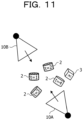
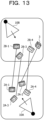
- FIGs. 11 to 15 are diagrams for describing processing of the robust estimation unit.
- the description will be given on the basis of the sensor 10A and the sensor 10B.
- the robust estimation unit 164 associates the targets 2 (foreground objects 3) observed at the same time point. For example, the robust estimation unit 164 associates the target 2A-1 with the target 2B-1. The robust estimation unit 164 associates the target 2A-2 with the foreground object 3. The robust estimation unit 164 associates the target 2A-3 with the target 2B-3. The robust estimation unit 164 associates the target 2A-4 with the target 2B-4.
- the robust estimation unit 164 calculates the external parameter T BA that minimizes the sum of the distances between the positions of the corresponding pair of targets according to the above correspondence relationship. For example, robust estimation unit 164 optimizes the external parameter T BA between sensor 10A and sensor 10B using bundle estimation and maximum likelihood estimation after estimating an initial value, and finally calculates the external parameter T BA .
- the robust estimation unit 164 uses the external parameter T BA2 to correct the positions of the respective targets 2 (excluding the set of target 2A-2 and the foreground object 3) of the observation result 30B to the positions with reference to the sensor 10A, and calculates an average (second average value) of the distances between each of the associated targets. For example, the result of correcting the positions of the respective targets 2 (excluding the set of the target 2A-2 and the foreground object 3) to the positions with reference to the sensor 10A, using the external parameter T BA2 becomes the positions illustrated in FIG. 15 .
- the robust estimation unit 165 executes the above processing after the detection result table 142 is generated by the detection unit 160 and before the processing by the specifying unit 161, the graph generation unit 162, and the parameter generation unit 163 is started. Thereby, the noise (foreground object 3) that is erroneous detection of something other than the target can be removed.
- the integration unit 153 acquires the background difference data of each of the sensors 10A to 10D from the acquisition unit 151.
- the integration unit 153 converts the relationship between each pixel and the distance value included in the background difference data into the relationship between the point cloud and the coordinates of the orthogonal coordinate system of each point, using the conversion table.
- the converted background difference data is referred to as "three-dimensional point cloud data".
- the conversion table is a table that defines the relationship between the pixel position and the distance value, and the point and the coordinates of the orthogonal coordinate system.
- the integration unit 153 integrates the three-dimensional point cloud data of the sensor 10A and the three-dimensional point cloud data of the sensors 10B to 10D adjusted to the position and orientation of the sensor 10A to generate one three-dimensional point cloud data.
- the integration unit 153 outputs the generated three-dimensional point cloud data to the fitting processing unit 154.
- the integration unit 153 repeatedly executes the above processing each time the background difference data of the sensors 10A to 10D is acquired from the acquisition unit 151.
- the fitting processing unit 154 is a processing unit that executes fitting that applies a three-dimensional model data of the object to the three-dimensional point cloud data.
- the fitting processing unit 154 specifies skeleton model data of the object on the basis of the fitting result.
- the skeleton model data includes position information of each joint.
- the fitting processing unit outputs the skeleton model data to the evaluation unit 155.
- the fitting processing unit repeatedly executes the above processing every time the three-dimensional point cloud data is acquired from the integration unit 153.
- the evaluation unit 155 is a processing unit that acquires the skeleton model data in time series and evaluates the performance of the object on the basis of transition of each joint coordinate of the skeleton model data. For example, the evaluation unit 155 evaluates the performance of the object using a table (not illustrated) that defines the transition of each joint coordinate, a type of technique, and success or failure of technique, and outputs the evaluation result to the display unit 130.
- scoring competitions include, in addition to gymnastics, trampoline, swim diving, figure skating, karate style, ballroom dance, snowboarding, skateboarding, ski aerial, and surfing. Furthermore, it may also be applied to form check of classical ballet, ski jump, mogul air, turn, baseball, and basketball, and the like. Furthermore, it may also be applied to competitions such as kendo, judo, wrestling, and sumo. Moreover, it may also be used to evaluate whether or not a weight lifting barbell has been lifted.
- FIG. 16 is a flowchart illustrating a processing procedure of the information processing apparatus according to the present embodiment 1.
- the acquisition unit 151 of the information processing apparatus 100 acquires the distance image data from the sensor 10 (step S10).
- the acquisition unit 151 takes the difference between the distance image data and the background image data and generates the background difference data (step S11).
- the detection unit 160 of the information processing apparatus 100 detects the target from the background difference data, and registers the point cloud information of the target in the detection result table 142 (step S12). In the case of not terminating the target detection (steps S13, No), the information processing apparatus 100 proceeds to step S10 again. On the other hand, in the case of terminating the target detection (steps S13, Yes), the information processing apparatus 100 proceeds to step S14.
- the external parameter generation processing unit 152 (specifying unit 161 and graph generation unit 162) of the information processing apparatus 100 executes the sensor connectivity graph generation processing (step S14).
- the parameter generation unit 163 of the information processing apparatus 100 applies the Bellman-Ford method to a sensor connectivity graph 31 for a set (i ref , i tar ) of a reference sensor i ref and another sensor i tar to obtain the shortest path (step S15).
- the reference sensor i ref corresponds to the sensor 10A.
- the another sensor i tar corresponds to the sensor 10B, 10C, or 10D.
- the parameter generation unit 163 selects the path P of the sensor group on the basis of the search result of the shortest path (step S16).
- the parameter generation unit 163 calculates the initial value of the external parameter of the sensor i tar using the singular value decomposition on the basis of the order of the path P (step S17).
- the parameter generation unit 163 optimizes the external parameter of the sensor i tar by bundle adjustment and maximum likelihood estimation (step S18).
- the parameter generation unit 163 stores the external parameter in the external parameter table 143 (step S19).
- the processing of step S19 also corresponds to the processing of transmitting the external parameter to an external device.
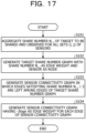
- FIG. 17 is a flowchart illustrating a processing procedure of the sensor connectivity graph generation processing.
- the specifying unit 161 of the information processing apparatus 100 aggregates the share number N i, j of the target to be shared and observed for all the sets of sensors (i, j) (step S101).
- the graph generation unit 162 of the information processing apparatus 100 generates the target share number graph 50 with the share number N i, j as an edge weight and the sensor 10 as a node (step S102).
- the graph generation unit 162 generates the sensor connectivity graph in which the edges satisfying the share number N i, j ⁇ 3 are left among the edges of the target share number graph (step S103).
- the graph generation unit 162 generates the sensor connectivity graph having -2log ⁇ as the edge weight for each edge of the sensor connectivity graph (step S104).
- the information processing apparatus 100 executes observations by the sensors 10A to 10D while moving the target 2 at each time point, and specifies the share number indicating the number of times of a time point when the target 2 is detected at the same time point.
- the information processing apparatus 100 generates the target share number graph 50 in which the share number is the weight of the edge, and generates the sensor connectivity graph 51 obtained by leaving the edges E having the weight that is a predetermined number or more from the target share number graph 50.
- the set of sensors in which the number of times the target 2 is observed at the same time point is a predetermined number or more can be specified.
- the information processing apparatus 100 calculates the variance ⁇ 2 of the positions of the target group observed by the set of two sensors at time points, sets "-2log ⁇ " as the weight of each edge E, and reflects the variance of the targets in the sensor connectivity graph 51. In the sensor connectivity graph with the "-2log ⁇ " as the weight of each edge E, the smaller the edge weight, the larger the spatial variance of the positions of the target group observed by the set of two sensors.
- the information processing apparatus 100 specifies the path that minimizes the sum of the edges E, and specifies the order of the sensors 10 to be selected when calculating the external parameters on the basis of the specified path.
- the order of the sensors in which the spatial variance of the positions of the target group becomes as large as possible can be specified so that the calculation of the external parameters of the sensors 10 becomes stable. Therefore, according to the information processing apparatus 100, information indicating relative positional relationships such as an arrangement positional relationship and an angle of view relationship may be accurately generated for three or more sensors,.
- the information processing apparatus 100 executes the external calibration using the cylindrical target 2 as a target and generates the external parameters, but the present embodiment is not limited thereto.
- the information processing apparatus 100 may also use a spherical marker as a target.
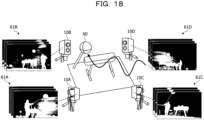
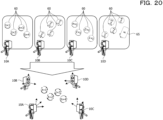
- FIGs. 18 to 20 are diagrams illustrating an example of external calibration using a spherical marker.
- the user observes the spherical marker 60 by the sensors 10A to 10D while moving the spherical marker 60 at each time point.
- the spherical marker 60 is moved by a user (not illustrated).
- the sensor 10A observes an observation result 61A at each time point.
- the sensor 10B observes an observation result 61B at each time point.
- the sensor 10C observes an observation result 61C at each time point.
- the sensor 10D observes an observation result 61D at each time point.
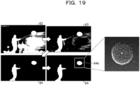
- the description proceeds to FIG. 19 .
- the information processing apparatus 100 generates a background difference data 63 by taking the difference between distance image data 62 and the background image data.
- the information processing apparatus 100 generates background difference data 64 by removing noise from background difference data 63.
- the information processing apparatus 100 detects a spherical marker 64a from the background difference data 64.
- the information processing apparatus 100 can robustly detect the spherical marker 64a with respect to the measurement noise by fitting the spherical marker 64a.
- the information processing apparatus 100 generates the sensor connectivity graph on the basis of the share number of the spherical marker 60 and the variance of the spherical markers 60, and generates the external parameters.
- the information processing apparatus 100 may accurately generate information (external parameters) indicating relative positional relationships such as an arrangement positional relationship and an angle of view relationship, even using the spherical marker 60 instead of the target 2.
- the information processing system according to the present embodiment 2 arranges a target at a predetermined position and measures the target, thereby calculating position and orientation of an object other than sensors in addition to generating external parameters.
- a target at a predetermined position and measures the target, thereby calculating position and orientation of an object other than sensors in addition to generating external parameters.
- description will be given using gymnastic equipment as the object other than sensors, but the present embodiment is not limited to the example.
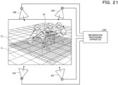
- FIG. 21 is a diagram for describing an arrangement position of a target. As illustrated in FIG. 21 , gymnastic equipment 70 is arranged. Furthermore, sensors 10A to 10D are arranged around the gymnastic equipment 70. Each of the sensors 10A to 10D is connected to the information processing apparatus 200.
- Target P1 is arranged directly above the center of gymnastic equipment 70.
- Target P2 is arranged on a y axis of the gymnastic equipment 70 and at a height H of an upper surface of the gymnastic equipment 70.
- Targets P3 to Pn are arranged at positions higher than P2 on a mat 72 having the same height from a floor surface 71. The heights from the floor surface 71 to the targets P3 to Pn are the same.
- the number of targets P3 to Pn being 3 or more is a condition.
- the information processing apparatus 200 calculates an Xa axis, a Ya axis, a Za axis, and an origin Oa of a coordinate system of the gymnastic equipment 70, using the positions of the targets P1 to Pn observed during execution of external calibration after the execution of external calibration, similarly to the information processing apparatus 100 of the embodiment 1.
- the information processing apparatus 200 fits a plane to the targets P3 to Pn, and specifies a normal of the plane as the Za axis.
- the information processing apparatus 200 calculates the Xa axis on the basis of the equations (3) and (4).
- P1 and P2 included in the equation (3) indicate the positions of the targets P1 and P2.
- the information processing apparatus 200 calculates the Ya axis on the basis of the equation (5).
- Ya Za ⁇ Xa
- the information processing apparatus 200 calculates the origin Oa on the basis of the equation (6).
- H included in the equation (6) corresponds to the height of the upper surface of the gymnastic equipment 70.
- dot (v, Za) included in equation (6) is a function that calculates an inner product of v and Za.
- Oa P1 ⁇ H ⁇ dot v , Za Za
- the background image table 241 is a table that stores background image data (distance image data) measured by each of the sensors 10A to 10D in the state of absence of the target Pn.
- the detection result table 242 is a table that stores the point cloud and the position of the target Pn detected at each time point on the basis of the observation result of the sensor 10.
- the data structure of the detection result table 242 corresponds to the data structure of the detection result table 142 described with reference to FIG. 8 . Note that the target will be the target Pn instead of the target 2.
- the external parameter table 243 is a table that stores the external parameters generated by the external parameter generation processing unit 252, which will be described below.
- the data structure of the external parameter table 243 corresponds to the external parameter table 143 described with reference to FIG. 9 .
- the coordinate conversion parameter data 244 has data of the coordinate conversion parameter T aA .
- the coordinate conversion parameter T aA is a parameter that converts the Xa axis, Ya axis, Za axis, and origin Oa into coordinates with reference to the sensor 10A.
- the control unit 250 includes an acquisition unit 251, an external parameter generation processing unit 252, a calculation unit 253, an integration unit 254, a fitting processing unit 255, and an evaluation unit 256.
- the control unit 250 is implemented by CPU, MPU, a hard-wired logic such as ASIC or FPGA, or the like.
- the acquisition unit 251 is a processing unit that acquires the distance image data from the sensor 10 via the communication unit 210. For example, timing at which the acquisition unit 251 acquires the distance image data is instructed by the user who operates the input unit 220.
- the acquisition unit 251 takes a difference between the distance image data and the background image data stored in the background image table 241, and generates background difference image data.
- the acquisition unit 251 outputs the background difference image data to the external parameter generation processing unit 252.
- Other descriptions regarding the acquisition unit 251 are similar to the descriptions regarding the acquisition unit 151 described in the embodiment 1.
- the external parameter generation processing unit 252 is a processing unit that generates external parameters on the basis of data stored in the detection result table 242.
- the external parameter generation processing unit 252 stores the generated external parameters in the external parameter table 243.
- Description of the external parameter generation processing unit 252 is similar to the description of the external parameter generation processing unit 252 described in the embodiment 1.
- the calculation unit 253 is a processing unit that calculates the Xa axis, Ya axis, Za axis, and origin Oa of the coordinate system of the gymnastic equipment 70.
- the calculation unit 253 uses the sensor 10A as the reference sensor 10 and adjusts the three-dimensional point cloud data of the targets P1 to Pn observed by the sensors 10B to 10D to the position and orientation of the sensor 10A.
- the three-dimensional point cloud data of the targets P1 to Pn observed by the sensors 10B to 10D are stored in the detection result table 242.
- the calculation unit 253 uses an external parameter T BA to adjust the three-dimensional point cloud data observed by the sensor 10B to the position and orientation of the sensor 10A.
- the calculation unit 253 uses an external parameter T CA to adjust the three-dimensional point cloud data observed by the sensor 10C to the position and orientation of the sensor 10A.
- the calculation unit 253 uses an external parameter T DA to adjust the three-dimensional point cloud data observed by the sensor 10D to the position and orientation of the sensor 10A.
- the calculation unit 253 acquires each external parameter from the external parameter table 243.
- the calculation unit 253 adjusts the three-dimensional point cloud data of the targets P1 to Pn observed by the sensors 10B to 10D to the position and orientation of the sensor 10A, and then integrates the three-dimensional point cloud data of the targets P1 to Pn observed by the sensors 10A to 10D.
- the calculation unit 253 sets the center of gravity position of the targets P1 to Pn as the position of the targets P1 to Pn.
- the calculation unit 253 fits a plane to the targets P3 to Pn, and specifies the normal of the plane as the Za axis.
- the calculation unit 253 calculates the Xa axis on the basis of the equations (3) and (4).
- the calculation unit 253 calculates the Ya axis on the basis of the equation (5).
- the calculation unit 253 calculates the origin Oa on the basis of the equation (6).
- the calculation unit 253 calculates the coordinate conversion parameter T aA that converts the Xa axis, Ya axis, Za axis, and origin Oa into coordinates with reference to the sensor 10A on the basis of the equations (7) and (8).
- the calculation unit 253 stores the coordinate conversion parameter T aA in the storage unit 240.
- the integration unit 254, the fitting processing unit 255, and the evaluation unit 256 execute processing when the external calibration is completed by the external parameter generation processing unit 252 and the object starts performance.
- the integration unit 254 is a processing unit that integrates the three-dimensional point cloud data of the sensor 10A and the three-dimensional point cloud data of the sensors 10B to 10D adjusted to the position and orientation of the sensor 10A to generate one three-dimensional point cloud data. Description of the integration unit 254 is similar to the description of the integration unit 153 described in the embodiment 1.
- the integration unit 254 multiplies the coordinates of the integrated three-dimensional point cloud data by the coordinate conversion parameter T aA .
- the three-dimensional point cloud data of the coordinate system with reference to the sensor 10A can be converted into the three-dimensional point cloud data of the coordinate system of the gymnastic equipment 70.
- the fitting processing unit 255 is a processing unit that executes fitting that applies a three-dimensional model data of the object to the three-dimensional point cloud data.
- the fitting processing unit 255 specifies skeleton model data of the object on the basis of the fitting result.
- the skeleton model data includes position information of each joint.
- the fitting processing unit outputs the skeleton model data to the evaluation unit 256.
- the fitting processing unit 255 repeatedly executes the above processing every time the three-dimensional point cloud data is acquired from the integration unit 254.
- the evaluation unit 256 is a processing unit that acquires the skeleton model data in time series and evaluates the performance of the object on the basis of transition of each joint coordinate of the skeleton model data. For example, the evaluation unit 256 evaluates the performance of the object using a table (not illustrated) that defines the transition of each joint coordinate, a type of technique, and success or failure of technique, and outputs the evaluation result to the display unit 230.
- the evaluation unit 256 may also display the three-dimensional model in an animation, using the coordinate system of the gymnastic equipment 70. Furthermore, the evaluation unit 256 may output the instruction to perform conversion into the coordinate system of the gymnastic equipment 70 to the integration unit 254, and may also convert the coordinates of the object into the coordinate system of the gymnastic equipment 70 and display the object.
- FIG. 23 is a flowchart illustrating a processing procedure of the information processing apparatus according to the present embodiment 2.
- the acquisition unit 251 of the information processing apparatus 200 acquires distance image data from the sensor 10 (step S201).
- the acquisition unit 251 takes a difference between the distance image data and the background image data and generates background difference data (step S202).
- the external parameter generation processing unit 252 of the information processing apparatus 200 detects the target from the background difference data, and registers the point cloud information of the target in the detection result table 242 (step S203). In the case of not terminating the target detection (steps S204, No), the information processing apparatus 200 proceeds to step S201 again. On the other hand, in the case of terminating the target detection (steps S204, Yes), the information processing apparatus 200 proceeds to step S205.
- the external parameter generation processing unit 252 of the information processing apparatus 200 executes the sensor connectivity graph generation processing (step S205).
- the sensor connectivity graph generation processing in step S205 corresponds to the processing procedure of the sensor connectivity graph generation processing described with reference to FIG. 17 of the embodiment 1.
- the external parameter generation processing unit 252 of the information processing apparatus 200 applies the Bellman-Ford method to a sensor connectivity graph 31 for a set (i ref , i tar ) of a reference sensor i ref and another sensor i tar to obtain the shortest path (step S206).
- the reference sensor i ref corresponds to the sensor 10A.
- the another sensor i tar corresponds to the sensor 10B, 10C, or 10D.
- the external parameter generation processing unit 252 selects the path P of the sensor group on the basis of the search result of the shortest path (step S207).
- the external parameter generation processing unit 252 calculates the initial value of the external parameter of the sensor i tar using the singular value decomposition on the basis of the order of the path P (step S208).
- the external parameter generation processing unit 252 optimizes the external parameter of the sensor i tar by bundle adjustment and maximum likelihood estimation (step S209).
- the external parameter generation processing unit 252 stores the external parameters in the external parameter table 243 (step S210).
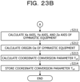
- the calculation unit 253 of the information processing apparatus 200 calculates the Xa axis, Ya axis, and Za axis of the gymnastic equipment 70 (step S211).
- the calculation unit 253 calculates the origin Oa of the gymnastic equipment 70 (step S212).
- the calculation unit 253 calculates the coordinate conversion parameter T aA (step S213).
- the calculation unit 253 stores the coordinate conversion parameter T aA in the coordinate conversion parameter data 244 (step S214).
Landscapes
- Engineering & Computer Science (AREA)
- Physics & Mathematics (AREA)
- General Physics & Mathematics (AREA)
- Computer Networks & Wireless Communication (AREA)
- Electromagnetism (AREA)
- Radar, Positioning & Navigation (AREA)
- Remote Sensing (AREA)
- Theoretical Computer Science (AREA)
- Computer Vision & Pattern Recognition (AREA)
- Length Measuring Devices With Unspecified Measuring Means (AREA)
- Length Measuring Devices By Optical Means (AREA)
- Measurement Of Optical Distance (AREA)
- Image Analysis (AREA)
Claims (12)
- Erzeugungsverfahren, das von einem Computer ausgeführt wird, wobei das Verfahren Folgendes umfasst:Erhalten von Erfassungsergebnissen eines Ziels (2) zu einer Vielzahl von Zeitpunkten durch drei oder mehr Sensoren (10);Bestimmen einer Anteilszahl, die eine Anzahl von Malen eines Zeitpunkts anzeigt, wenn das Ziel (2) zu einem gleichen Zeitpunkt unter der Vielzahl von Zeitpunkten durch jeden Satz von zwei Sensoren (10) erfasst wird; unter den drei oder mehr Sensoren (10); auf der Grundlage, ob jeder der drei oder mehr Sensoren (10) das Ziel (2) zu jedem Zeitpunkt erfasst hat;Erzeugen eines Zielanteilszahlgraphen (50), in dem die Anteilszahl ein Gewicht einer Kante ist;Erzeugen eines Sensor-Konnektivitätsgraphen (51), der erhalten wird, indem die Kante mit dem Gewicht, das eine vorbestimmte Zahl oder mehr ist, aus dem Zielanteilszahlgraphen (50) weggelassen wird, wobei ein Satz von Knoten, die in dem Sensor-Konnektivitätsgraphen (51) verbunden sind, einen Satz von Sensoren (10) anzeigt, bei denen die Anzahl der Beobachtungen des Ziels (2) zu demselben Zeitpunkt eine vorbestimmte Anzahl oder mehr beträgt;
wobei das Verfahren gekennzeichnet ist durchBerechnen einer Varianz σ der Positionen des Ziels (2) zu der Vielzahl von Zeitpunkten, die von dem Satz von zwei Sensoren (10) zu den Zeitpunkten beobachtet werden,Festlegen einer logarithmischen Funktion der Varianz σ als Gewicht der einzelnen Kanten;Reflektieren der Varianz σ der Ziele (2) als Sensor im Sensor-Konnektivitätsgraphen;Bestimmen eines Pfades, der die Summe der Kanten minimiert; undBestimmen der Reihenfolge der Sensoren (10), die ausgewählt werden sollen, wenn externe Parameter auf Basis des festgelegten Pfades berechnet werden;wobei eine Reihenfolge der Sensoren (10) festgelegt wird, in der die Varianz der Positionen des Ziels (2) möglichst groß wird, sodass die Berechnung der externen Parameter der Sensoren (10) stabil wird. - Erzeugungsverfahren nach Anspruch 1, wobeieine Form des Ziels (2) eine Kugel ist, unddas Erzeugungsverfahren weiter Folgendes umfasst: Erfassen der im Erfassungsergebnis eingeschlossenen Kugel als Ziel (2).
- Erzeugungsverfahren nach Anspruch 1, weiter umfassend:wiederholtes Ausführen der Verarbeitung, einschließend:Festlegen, für jeden Satz von zwei Sensoren (10), einer Vielzahl von Sätzen von Zielen (2), in denen die Ziele (2), die zum selben Zeitpunkt unter der Vielzahl von Zeitpunkten detektiert werden, einander zugeordnet sind,Auswählen einiger Sätze von Zielen (2) aus der Vielzahl der Sätze von Zielen (2), undBerechnen der Position und Orientierung von Sensoren, die den kürzesten Abstand zwischen den Positionen der Ziele (2) in den ausgewählten Sätzen von Zielen (2) aufweisen, während der Satz von auszuwählenden Zielen (2) geändert wird; undweiteres Ausführen der Verarbeitung zum Ausschließen eines der zu der Vielzahl von Zeitpunkten erfassten Ziele (2) auf der Grundlage eines Minimalwerts des Abstands zwischen den Positionen der Ziele (2).
- Erzeugungsverfahren nach Anspruch 1, 2 oder 3, wobeidas Ziel (2) an einer vorbestimmten Position in Bezug auf ein anderes Objekt als die drei oder mehr Sensoren (10) zu der Vielzahl von Zeitpunkten angeordnet ist, unddas Erzeugungsverfahren weiter Folgendes umfasst: Berechnen von Ursprungskoordinaten eines Koordinatensystems in Bezug auf das Objekt auf der Grundlage der Positionen des Ziels (2), die zu der Vielzahl von Zeitpunkten von einem der drei oder mehr Sensoren (10) erfasst wurden.
- Erzeugungsprogrammen, das Anweisungen umfasst, die, wenn das Erzeugungsprogrammen von einem Computer ausgeführt wird, den Computer veranlassen, eine Verarbeitung durchzuführen, einschließend:Erhalten von Erfassungsergebnissen eines Ziels (2) zu einer Vielzahl von Zeitpunkten durch drei oder mehr Sensoren (10);Bestimmen einer Anteilszahl, die eine Anzahl von Malen eines Zeitpunkts anzeigt, wenn das Ziel (2) zu einem gleichen Zeitpunkt unter der Vielzahl von Zeitpunkten durch jeden Satz von zwei Sensoren (10) erfasst wird; unter den drei oder mehr Sensoren (10); auf der Grundlage, ob jeder der drei oder mehr Sensoren (10) das Ziel (2) zu jedem Zeitpunkt erfasst hat;Erzeugen eines Zielanteilszahlgraphen (50), in dem die Anteilszahl ein Gewicht einer Kante ist;Erzeugen eines Sensor-Konnektivitätsgraphen (51), der erhalten wird, indem die Kante mit dem Gewicht, das eine vorbestimmte Zahl oder mehr ist, aus dem Zielanteilszahlgraphen (50) weggelassen wird, wobei ein Satz von Knoten, die in dem Sensor-Konnektivitätsgraphen (51) verbunden sind, einen Satz von Sensoren (10) anzeigt, bei denen die Anzahl der Beobachtungen des Ziels (2) zu demselben Zeitpunkt eine vorbestimmte Anzahl oder mehr beträgt;dadurch gekennzeichnet, dass der Computer veranlasst wird, eine weitere Verarbeitung durchzuführen, einschließend:Berechnen einer Varianz σ der Positionen des Ziels (2) zu der Vielzahl von Zeitpunkten, die von dem Satz von zwei Sensoren zu den Zeitpunkten beobachtet werden,Festlegen einer logarithmischen Funktion der Varianz σ als Gewicht der einzelnen Kanten;Reflektieren der Varianz σ der Ziele (2) als Sensor im Sensor-Konnektivitätsgraphen;Bestimmen eines Pfades, der die Summe der Kanten minimiert; undBestimmen der Reihenfolge der Sensoren (10), die ausgewählt werden sollen, wenn externe Parameter auf Basis des festgelegten Pfades berechnet werden;wobei eine Reihenfolge der Sensoren (10) festgelegt wird, in der die Varianz der Positionen des Ziels (2) möglichst groß wird, sodass die Berechnung der externen Parameter der Sensoren (10) stabil wird.
- Erzeugungsprogrammen nach Anspruch 5, wobeieine Form des Ziels (2) eine Kugel ist, unddie Verarbeitung weiter Folgendes einschließt: Erfassen der im Erfassungsergebnis eingeschlossenen Kugel als Ziel (2).
- Erzeugungsprogrammen nach Anspruch 5, wobei die Verarbeitung weiter Folgendes einschließt:wiederholtes Ausführen der Verarbeitung:Festlegen, für jeden Satz von zwei Sensoren (10), einer Vielzahl von Sätzen von Zielen (2), in denen die Ziele (2), die zum selben Zeitpunkt unter der Vielzahl von Zeitpunkten detektiert werden, einander zugeordnet sind,Auswählen einiger Sätze von Zielen (2) aus der Vielzahl der Sätze von Zielen (2), undBerechnen der Position und Orientierung von Sensoren (10), die den kürzesten Abstand zwischen den Positionen der Ziele (2) in den ausgewählten Sätzen von Zielen (2) aufweisen, während der Satz von auszuwählenden Zielen (2) geändert wird; undweiteres Ausführen der Verarbeitung zum Ausschließen eines der zu der Vielzahl von Zeitpunkten erfassten Ziele (2) auf der Basis eines Minimalwerts des Abstands zwischen den Positionen der Ziele (2).
- Erzeugungsprogrammen nach Anspruch 5, 6 oder 7, wobeidas Ziel an einer vorbestimmten Position in Bezug auf ein anderes Objekt als die drei oder mehr Sensoren (10) zu der Vielzahl von Zeitpunkten angeordnet ist, unddie Verarbeitung weiter Folgendes einschließt: Berechnen von Ursprungskoordinaten eines Koordinatensystems in Bezug auf das Objekt auf der Grundlage der Positionen des Ziels, die zu der Vielzahl von Zeitpunkten von einem der drei oder mehr Sensoren (10) erfasst wurden, weiter ausgeführt wird.
- Informationsverarbeitungseinrichtung (100), umfassend:eine Bestimmungseinheit (161), die zu Folgendem konfiguriert ist:
Erhalten von Erfassungsergebnissen eines Ziels zu einer Vielzahl von Zeitpunkten durch drei oder mehr Sensoren (10); und Bestimmen einer Anteilszahl, die eine Anzahl von Malen eines Zeitpunkts anzeigt, wenn das Ziel zu einem gleichen Zeitpunkt unter der Vielzahl von Zeitpunkten durch jeden Satz von zwei Sensoren (10) erfasst wird; unter den drei oder mehr Sensoren (10); auf der Grundlage, ob jeder der drei oder mehr Sensoren (10) das Ziel zu jedem Zeitpunkt erfasst hat;eine Graphenerzeugungseinheit (162), die zu Folgendem konfiguriert ist:wobei die Einrichtung dadurch gekennzeichnet ist, dass sie Folgendes umfasst:
Erzeugen eines Zielanteilszahlgraphen (50), in dem die Anteilszahl ein Gewicht einer Kante ist; Erzeugen eines Sensor-Konnektivitätsgraphen (51), der erhalten wird, indem die Kante mit dem Gewicht, das eine vorbestimmte Zahl oder mehr ist, aus dem Zielanteilszahlgraphen (50) weggelassen wird, wobei ein Satz von Knoten, die in dem Sensor-Konnektivitätsgraphen (51) verbunden sind, einen Satz von Sensoren anzeigt, bei denen die Anzahl der Beobachtungen des Ziels (2) zu demselben Zeitpunkt eine vorbestimmte Anzahl oder mehr beträgt;eine Parametererzeugungseinheit (163), die zu Folgendem konfiguriert ist: Berechnen einer Varianz σ der Positionen des Ziels (2) zu der Vielzahl von Zeitpunkten, die von dem Satz von zwei Sensoren zu den Zeitpunkten beobachtet werden, Festlegen einer logarithmischen Funktion der Varianz σ als Gewicht der einzelnen Kanten; Reflektieren der Varianz σ der Ziele (2) als Sensor im Sensor-Konnektivitätsgraphen; Bestimmen eines Pfades, der die Summe der Kanten minimiert; und Bestimmen der Reihenfolge der Sensoren (10), die ausgewählt werden sollen, wenn externe Parameter auf Basis des festgelegten Pfades berechnet werden;wobei eine Reihenfolge der Sensoren festgelegt wird, in der die Varianz der Positionen des Ziels möglichst groß wird, sodass die Berechnung der externen Parameter der Sensoren (10) stabil wird. - Informationsverarbeitungseinrichtung (100) nach Anspruch 9, wobeieine Form des Ziels eine Kugel ist, unddie Informationsverarbeitungseinrichtung (100) weiter Folgendes umfasst: eine Erfassungseinheit, die so konfiguriert ist, dass sie die in dem Erfassungsergebnis eingeschlossenen Kugel erfasst, da das Ziel weiter eingeschlossen ist.
- Informationsverarbeitungseinrichtung (100) nach Anspruch 9, weiter umfassend:eine Einheit zur robusten Schätzung (164), die zur wiederholten Ausführung von Folgendem konfiguriert ist: Verarbeitung des Festlegens, für jeden Satz von zwei Sensoren (10), einer Vielzahl von Sätzen von Zielen (2), in denen die Ziele (2), die zum selben Zeitpunkt unter der Vielzahl von Zeitpunkten detektiert werden, einander zugeordnet sind, Auswählen einiger Sätze von Zielen (2) aus der Vielzahl der Sätze von Zielen (2), und Berechnen der Position und Orientierung von Sensoren (10), die den kürzesten Abstand zwischen den Positionen der Ziele (2) in den ausgewählten Sätzen von Zielen (2) aufweisen, während der Satz von auszuwählenden Zielen (2) geändert wird, undAusführen der Verarbeitung zum Ausschließen eines der zu der Vielzahl von Zeitpunkten erfassten Ziele (2) auf der Grundlage eines Minimalwerts des Abstands zwischen den Positionen der Ziele (2).
- Informationsverarbeitungseinrichtung (100) nach Anspruch 9, 10 oder 11, wobeidas Ziel an einer vorbestimmten Position in Bezug auf ein anderes Objekt als die drei oder mehr Sensoren (10) zu der Vielzahl von Zeitpunkten angeordnet ist, unddie Informationsverarbeitungseinrichtung (100) weiter eine Berechnungseinheit umfasst, die so konfiguriert ist, dass sie Ursprungskoordinaten eines Koordinatensystems in Bezug auf das Objekt auf der Grundlage der Positionen des Ziels, das zu der Vielzahl von Zeitpunkten durch einen der drei oder mehr Sensoren (10) erfasst wird, berechnet; weiter eingeschlossen ist.
Applications Claiming Priority (1)
| Application Number | Priority Date | Filing Date | Title |
|---|---|---|---|
| PCT/JP2019/039019 WO2021064925A1 (ja) | 2019-10-02 | 2019-10-02 | 生成方法、生成プログラムおよび情報処理装置 |
Publications (3)
| Publication Number | Publication Date |
|---|---|
| EP4040104A1 EP4040104A1 (de) | 2022-08-10 |
| EP4040104A4 EP4040104A4 (de) | 2022-11-02 |
| EP4040104B1 true EP4040104B1 (de) | 2024-12-04 |
Family
ID=75336826
Family Applications (1)
| Application Number | Title | Priority Date | Filing Date |
|---|---|---|---|
| EP19947861.1A Active EP4040104B1 (de) | 2019-10-02 | 2019-10-02 | Erzeugung von angaben über relative positionsverhältnisse für drei oder mehr sensoren |
Country Status (5)
| Country | Link |
|---|---|
| US (1) | US20220179085A1 (de) |
| EP (1) | EP4040104B1 (de) |
| JP (1) | JP7188612B2 (de) |
| CN (1) | CN114430800B (de) |
| WO (1) | WO2021064925A1 (de) |
Families Citing this family (1)
| Publication number | Priority date | Publication date | Assignee | Title |
|---|---|---|---|---|
| CN115406374B (zh) * | 2022-08-03 | 2024-12-31 | 广州启量信息科技有限公司 | 一种基于点云图的投影面积计算方法及装置 |
Family Cites Families (14)
| Publication number | Priority date | Publication date | Assignee | Title |
|---|---|---|---|---|
| JPH08287608A (ja) * | 1995-04-18 | 1996-11-01 | Fujitsu Ltd | 情報再生装置及び最尤等化検出方法 |
| JP3647584B2 (ja) * | 1996-12-26 | 2005-05-11 | 富士通株式会社 | 学習型自己定位装置 |
| EP1349114A3 (de) * | 2002-03-19 | 2011-06-15 | Canon Kabushiki Kaisha | Sensorkalibrierungsgerät, Sensorkalibrierungsverfahren, Programm, Speichermedium, Informationsverarbeitungsverfahren und Informationsverarbeitungsgerät |
| EP1862969A1 (de) * | 2006-06-02 | 2007-12-05 | Eidgenössische Technische Hochschule Zürich | Verfahren und System zur Generierung einer Darstellung einer dynamisch wechselnden 3D-Szene |
| US9020187B2 (en) | 2011-05-27 | 2015-04-28 | Qualcomm Incorporated | Planar mapping and tracking for mobile devices |
| JP5708305B2 (ja) * | 2011-06-30 | 2015-04-30 | 富士通株式会社 | 画像認識装置、画像認識方法及び画像認識用コンピュータプログラム |
| JP6370038B2 (ja) * | 2013-02-07 | 2018-08-08 | キヤノン株式会社 | 位置姿勢計測装置及び方法 |
| JP6415291B2 (ja) * | 2014-12-09 | 2018-10-31 | キヤノン株式会社 | 情報処理装置、情報処理方法、プログラム |
| JP6621063B2 (ja) * | 2015-04-29 | 2019-12-18 | パナソニックIpマネジメント株式会社 | カメラ選択方法及び映像配信システム |
| JPWO2017159382A1 (ja) * | 2016-03-16 | 2019-01-24 | ソニー株式会社 | 信号処理装置および信号処理方法 |
| JP6685836B2 (ja) * | 2016-05-30 | 2020-04-22 | 株式会社東芝 | 情報処理装置、および、情報処理方法 |
| JP2019086476A (ja) | 2017-11-09 | 2019-06-06 | キヤノン株式会社 | 画像処理装置、画像処理方法、プログラムおよびキャリブレーション用具 |
| EP4250232B1 (de) * | 2017-11-20 | 2026-04-01 | Panasonic Intellectual Property Corporation of America | Verfahren und vorrichtung zur erzeugung dreidimensionaler punktgruppendaten, positionsschätzungsverfahren, vorrichtung zur erzeugung dreidimensionaler punktgruppendaten und positionsschätzungsvorrichtung |
| JP7119425B2 (ja) | 2018-03-01 | 2022-08-17 | ソニーグループ株式会社 | 画像処理装置、符号化装置、復号化装置、画像処理方法、プログラム、符号化方法及び復号化方法 |
-
2019
- 2019-10-02 EP EP19947861.1A patent/EP4040104B1/de active Active
- 2019-10-02 WO PCT/JP2019/039019 patent/WO2021064925A1/ja not_active Ceased
- 2019-10-02 CN CN201980100162.3A patent/CN114430800B/zh active Active
- 2019-10-02 JP JP2021550867A patent/JP7188612B2/ja active Active
-
2022
- 2022-02-21 US US17/676,273 patent/US20220179085A1/en active Pending
Also Published As
| Publication number | Publication date |
|---|---|
| EP4040104A1 (de) | 2022-08-10 |
| CN114430800A (zh) | 2022-05-03 |
| EP4040104A4 (de) | 2022-11-02 |
| US20220179085A1 (en) | 2022-06-09 |
| JP7188612B2 (ja) | 2022-12-13 |
| JPWO2021064925A1 (de) | 2021-04-08 |
| CN114430800B (zh) | 2024-04-02 |
| WO2021064925A1 (ja) | 2021-04-08 |
Similar Documents
| Publication | Publication Date | Title |
|---|---|---|
| US12056885B2 (en) | Method for automatically generating hand marking data and calculating bone length | |
| EP2808645B1 (de) | Kamerakalibrierungsvorrichtung, kamerakalibrierungsverfahren und kamerakalibrierungsprogramm | |
| JP5487298B2 (ja) | 3次元画像生成 | |
| JP5671281B2 (ja) | 位置姿勢計測装置、位置姿勢計測装置の制御方法及びプログラム | |
| US11386578B2 (en) | Image labeling system of a hand in an image | |
| US9317735B2 (en) | Information processing apparatus, information processing method, and program to calculate position and posture of an object having a three-dimensional shape | |
| CN111445531B (zh) | 一种多目相机导航方法、装置、设备及存储介质 | |
| JP2018026131A (ja) | 動作解析装置 | |
| US11989928B2 (en) | Image processing system | |
| JP2017004268A (ja) | 画像処理装置、画像処理方法および画像処理プログラム | |
| JP2019219248A (ja) | 点群処理装置、点群処理方法およびプログラム | |
| KR20210123177A (ko) | 압력을 이용한 운동 자세 구분 방법 및 장치 | |
| EP2372652A1 (de) | Verfahren zur Schätzung einer Fläche in einem Entfernungsbild und Entfernungsbildkamera | |
| EP3269302A1 (de) | Informationsverarbeitungsvorrichtung und informationsverarbeitungsverfahren | |
| EP4040104B1 (de) | Erzeugung von angaben über relative positionsverhältnisse für drei oder mehr sensoren | |
| JP2015111128A (ja) | 位置姿勢計測装置、位置姿勢計測方法、およびプログラム | |
| WO2018134866A1 (ja) | カメラ校正装置 | |
| US10042070B2 (en) | Method for locating mobile utensils presented before a network of magnetometers | |
| JP6306903B2 (ja) | 情報処理装置、情報処理装置の制御方法およびプログラム | |
| CN114694018B (zh) | 一种对象信息检测方法、装置和存储介质 | |
| CN102136139B (zh) | 目标姿态分析装置及其目标姿态分析方法 | |
| EP4292777A1 (de) | Assistenzsystem, bildverarbeitungsvorrichtung, assistenzverfahren und programm | |
| CN108292437A (zh) | 图像处理装置和方法 | |
| CN116433722A (zh) | 目标跟踪方法、电子设备、存储介质及程序产品 | |
| EP4075377A1 (de) | Erzeugungsverfahren, erzeugungsprogramm und informationsverarbeitungssystem |
Legal Events
| Date | Code | Title | Description |
|---|---|---|---|
| STAA | Information on the status of an ep patent application or granted ep patent |
Free format text: STATUS: THE INTERNATIONAL PUBLICATION HAS BEEN MADE |
|
| PUAI | Public reference made under article 153(3) epc to a published international application that has entered the european phase |
Free format text: ORIGINAL CODE: 0009012 |
|
| STAA | Information on the status of an ep patent application or granted ep patent |
Free format text: STATUS: REQUEST FOR EXAMINATION WAS MADE |
|
| 17P | Request for examination filed |
Effective date: 20220302 |
|
| AK | Designated contracting states |
Kind code of ref document: A1 Designated state(s): AL AT BE BG CH CY CZ DE DK EE ES FI FR GB GR HR HU IE IS IT LI LT LU LV MC MK MT NL NO PL PT RO RS SE SI SK SM TR |
|
| A4 | Supplementary search report drawn up and despatched |
Effective date: 20220930 |
|
| RIC1 | Information provided on ipc code assigned before grant |
Ipc: G01S 17/89 20200101ALI20220926BHEP Ipc: G01S 17/87 20200101ALI20220926BHEP Ipc: G01S 7/48 20060101ALI20220926BHEP Ipc: G06T 7/73 20170101ALI20220926BHEP Ipc: G06T 7/80 20170101ALI20220926BHEP Ipc: G06T 15/08 20110101ALI20220926BHEP Ipc: G01C 15/00 20060101ALI20220926BHEP Ipc: G01C 3/06 20060101ALI20220926BHEP Ipc: G01B 11/00 20060101AFI20220926BHEP |
|
| DAV | Request for validation of the european patent (deleted) | ||
| DAX | Request for extension of the european patent (deleted) | ||
| REG | Reference to a national code |
Ref country code: DE Ref legal event code: R079 Free format text: PREVIOUS MAIN CLASS: G01B0011000000 Ipc: G06T0007800000 Ref country code: DE Ref legal event code: R079 Ref document number: 602019063248 Country of ref document: DE Free format text: PREVIOUS MAIN CLASS: G01B0011000000 Ipc: G06T0007800000 |
|
| GRAP | Despatch of communication of intention to grant a patent |
Free format text: ORIGINAL CODE: EPIDOSNIGR1 |
|
| STAA | Information on the status of an ep patent application or granted ep patent |
Free format text: STATUS: GRANT OF PATENT IS INTENDED |
|
| RIC1 | Information provided on ipc code assigned before grant |
Ipc: G01S 17/89 20200101ALI20240917BHEP Ipc: G01S 17/87 20200101ALI20240917BHEP Ipc: G01S 7/48 20060101ALI20240917BHEP Ipc: G01C 15/00 20060101ALI20240917BHEP Ipc: G01C 3/06 20060101ALI20240917BHEP Ipc: G01B 11/00 20060101ALI20240917BHEP Ipc: G06T 15/08 20110101ALI20240917BHEP Ipc: G06T 7/73 20170101ALI20240917BHEP Ipc: G06T 7/80 20170101AFI20240917BHEP |
|
| GRAS | Grant fee paid |
Free format text: ORIGINAL CODE: EPIDOSNIGR3 |
|
| INTG | Intention to grant announced |
Effective date: 20240927 |
|
| GRAA | (expected) grant |
Free format text: ORIGINAL CODE: 0009210 |
|
| STAA | Information on the status of an ep patent application or granted ep patent |
Free format text: STATUS: THE PATENT HAS BEEN GRANTED |
|
| AK | Designated contracting states |
Kind code of ref document: B1 Designated state(s): AL AT BE BG CH CY CZ DE DK EE ES FI FR GB GR HR HU IE IS IT LI LT LU LV MC MK MT NL NO PL PT RO RS SE SI SK SM TR |
|
| REG | Reference to a national code |
Ref country code: CH Ref legal event code: EP |
|
| REG | Reference to a national code |
Ref country code: DE Ref legal event code: R096 Ref document number: 602019063248 Country of ref document: DE |
|
| REG | Reference to a national code |
Ref country code: IE Ref legal event code: FG4D |
|
| REG | Reference to a national code |
Ref country code: LT Ref legal event code: MG9D |
|
| REG | Reference to a national code |
Ref country code: NL Ref legal event code: MP Effective date: 20241204 |
|
| PG25 | Lapsed in a contracting state [announced via postgrant information from national office to epo] |
Ref country code: HR Free format text: LAPSE BECAUSE OF FAILURE TO SUBMIT A TRANSLATION OF THE DESCRIPTION OR TO PAY THE FEE WITHIN THE PRESCRIBED TIME-LIMIT Effective date: 20241204 |
|
| PG25 | Lapsed in a contracting state [announced via postgrant information from national office to epo] |
Ref country code: FI Free format text: LAPSE BECAUSE OF FAILURE TO SUBMIT A TRANSLATION OF THE DESCRIPTION OR TO PAY THE FEE WITHIN THE PRESCRIBED TIME-LIMIT Effective date: 20241204 |
|
| PG25 | Lapsed in a contracting state [announced via postgrant information from national office to epo] |
Ref country code: BG Free format text: LAPSE BECAUSE OF FAILURE TO SUBMIT A TRANSLATION OF THE DESCRIPTION OR TO PAY THE FEE WITHIN THE PRESCRIBED TIME-LIMIT Effective date: 20241204 |
|
| PG25 | Lapsed in a contracting state [announced via postgrant information from national office to epo] |
Ref country code: ES Free format text: LAPSE BECAUSE OF FAILURE TO SUBMIT A TRANSLATION OF THE DESCRIPTION OR TO PAY THE FEE WITHIN THE PRESCRIBED TIME-LIMIT Effective date: 20241204 |
|
| PG25 | Lapsed in a contracting state [announced via postgrant information from national office to epo] |
Ref country code: NO Free format text: LAPSE BECAUSE OF FAILURE TO SUBMIT A TRANSLATION OF THE DESCRIPTION OR TO PAY THE FEE WITHIN THE PRESCRIBED TIME-LIMIT Effective date: 20250304 |
|
| PG25 | Lapsed in a contracting state [announced via postgrant information from national office to epo] |
Ref country code: LV Free format text: LAPSE BECAUSE OF FAILURE TO SUBMIT A TRANSLATION OF THE DESCRIPTION OR TO PAY THE FEE WITHIN THE PRESCRIBED TIME-LIMIT Effective date: 20241204 Ref country code: GR Free format text: LAPSE BECAUSE OF FAILURE TO SUBMIT A TRANSLATION OF THE DESCRIPTION OR TO PAY THE FEE WITHIN THE PRESCRIBED TIME-LIMIT Effective date: 20250305 |
|
| PG25 | Lapsed in a contracting state [announced via postgrant information from national office to epo] |
Ref country code: RS Free format text: LAPSE BECAUSE OF FAILURE TO SUBMIT A TRANSLATION OF THE DESCRIPTION OR TO PAY THE FEE WITHIN THE PRESCRIBED TIME-LIMIT Effective date: 20250304 |
|
| PG25 | Lapsed in a contracting state [announced via postgrant information from national office to epo] |
Ref country code: NL Free format text: LAPSE BECAUSE OF FAILURE TO SUBMIT A TRANSLATION OF THE DESCRIPTION OR TO PAY THE FEE WITHIN THE PRESCRIBED TIME-LIMIT Effective date: 20241204 |
|
| REG | Reference to a national code |
Ref country code: AT Ref legal event code: MK05 Ref document number: 1748962 Country of ref document: AT Kind code of ref document: T Effective date: 20241204 |
|
| PG25 | Lapsed in a contracting state [announced via postgrant information from national office to epo] |
Ref country code: SM Free format text: LAPSE BECAUSE OF FAILURE TO SUBMIT A TRANSLATION OF THE DESCRIPTION OR TO PAY THE FEE WITHIN THE PRESCRIBED TIME-LIMIT Effective date: 20241204 |
|
| PG25 | Lapsed in a contracting state [announced via postgrant information from national office to epo] |
Ref country code: PL Free format text: LAPSE BECAUSE OF FAILURE TO SUBMIT A TRANSLATION OF THE DESCRIPTION OR TO PAY THE FEE WITHIN THE PRESCRIBED TIME-LIMIT Effective date: 20241204 |
|
| PG25 | Lapsed in a contracting state [announced via postgrant information from national office to epo] |
Ref country code: IS Free format text: LAPSE BECAUSE OF FAILURE TO SUBMIT A TRANSLATION OF THE DESCRIPTION OR TO PAY THE FEE WITHIN THE PRESCRIBED TIME-LIMIT Effective date: 20250404 |
|
| PG25 | Lapsed in a contracting state [announced via postgrant information from national office to epo] |
Ref country code: PT Free format text: LAPSE BECAUSE OF FAILURE TO SUBMIT A TRANSLATION OF THE DESCRIPTION OR TO PAY THE FEE WITHIN THE PRESCRIBED TIME-LIMIT Effective date: 20250404 |
|
| PG25 | Lapsed in a contracting state [announced via postgrant information from national office to epo] |
Ref country code: EE Free format text: LAPSE BECAUSE OF FAILURE TO SUBMIT A TRANSLATION OF THE DESCRIPTION OR TO PAY THE FEE WITHIN THE PRESCRIBED TIME-LIMIT Effective date: 20241204 |
|
| PG25 | Lapsed in a contracting state [announced via postgrant information from national office to epo] |
Ref country code: RO Free format text: LAPSE BECAUSE OF FAILURE TO SUBMIT A TRANSLATION OF THE DESCRIPTION OR TO PAY THE FEE WITHIN THE PRESCRIBED TIME-LIMIT Effective date: 20241204 Ref country code: AT Free format text: LAPSE BECAUSE OF FAILURE TO SUBMIT A TRANSLATION OF THE DESCRIPTION OR TO PAY THE FEE WITHIN THE PRESCRIBED TIME-LIMIT Effective date: 20241204 |
|
| PG25 | Lapsed in a contracting state [announced via postgrant information from national office to epo] |
Ref country code: SK Free format text: LAPSE BECAUSE OF FAILURE TO SUBMIT A TRANSLATION OF THE DESCRIPTION OR TO PAY THE FEE WITHIN THE PRESCRIBED TIME-LIMIT Effective date: 20241204 |
|
| PG25 | Lapsed in a contracting state [announced via postgrant information from national office to epo] |
Ref country code: CZ Free format text: LAPSE BECAUSE OF FAILURE TO SUBMIT A TRANSLATION OF THE DESCRIPTION OR TO PAY THE FEE WITHIN THE PRESCRIBED TIME-LIMIT Effective date: 20241204 |
|
| PG25 | Lapsed in a contracting state [announced via postgrant information from national office to epo] |
Ref country code: IT Free format text: LAPSE BECAUSE OF FAILURE TO SUBMIT A TRANSLATION OF THE DESCRIPTION OR TO PAY THE FEE WITHIN THE PRESCRIBED TIME-LIMIT Effective date: 20241204 |
|
| REG | Reference to a national code |
Ref country code: DE Ref legal event code: R097 Ref document number: 602019063248 Country of ref document: DE |
|
| PG25 | Lapsed in a contracting state [announced via postgrant information from national office to epo] |
Ref country code: SE Free format text: LAPSE BECAUSE OF FAILURE TO SUBMIT A TRANSLATION OF THE DESCRIPTION OR TO PAY THE FEE WITHIN THE PRESCRIBED TIME-LIMIT Effective date: 20241204 |
|
| PG25 | Lapsed in a contracting state [announced via postgrant information from national office to epo] |
Ref country code: DK Free format text: LAPSE BECAUSE OF FAILURE TO SUBMIT A TRANSLATION OF THE DESCRIPTION OR TO PAY THE FEE WITHIN THE PRESCRIBED TIME-LIMIT Effective date: 20241204 |
|
| PLBE | No opposition filed within time limit |
Free format text: ORIGINAL CODE: 0009261 |
|
| STAA | Information on the status of an ep patent application or granted ep patent |
Free format text: STATUS: NO OPPOSITION FILED WITHIN TIME LIMIT |
|
| REG | Reference to a national code |
Ref country code: CH Ref legal event code: L10 Free format text: ST27 STATUS EVENT CODE: U-0-0-L10-L00 (AS PROVIDED BY THE NATIONAL OFFICE) Effective date: 20251015 |
|
| PGFP | Annual fee paid to national office [announced via postgrant information from national office to epo] |
Ref country code: GB Payment date: 20250923 Year of fee payment: 7 |
|
| PGFP | Annual fee paid to national office [announced via postgrant information from national office to epo] |
Ref country code: FR Payment date: 20250925 Year of fee payment: 7 |
|
| REG | Reference to a national code |
Ref country code: CH Ref legal event code: U11 Free format text: ST27 STATUS EVENT CODE: U-0-0-U10-U11 (AS PROVIDED BY THE NATIONAL OFFICE) Effective date: 20251101 |
|
| 26N | No opposition filed |
Effective date: 20250905 |
|
| PGFP | Annual fee paid to national office [announced via postgrant information from national office to epo] |
Ref country code: DE Payment date: 20250923 Year of fee payment: 7 |
|
| PGFP | Annual fee paid to national office [announced via postgrant information from national office to epo] |
Ref country code: CH Payment date: 20251101 Year of fee payment: 7 |